
Chapter 3: Development tools and device platform
Abstract
In this chapter, we will set up a software development toolchain and install the platform libraries that we will use to create our device. To test out the board, we will try a simple Hello World program that uses a real-time operating system (RTOS) and go through the compile, download, and debug cycle. Once we have the basics working, we will set up a base project that adds a WiFi connection to your local network and add a file system to read and store data on an SD card. This will give us a basic platform that we can expand through the course of this book.
Keywords
CMSIS driver; WiFi module; File system; MDK ARM
Introduction
In this chapter, we will set up a software development toolchain and install the platform libraries that we will use to create our device. To test out the board, we will try a simple Hello World program that uses a real-time operating system (RTOS) and go through the compile, download, and debug cycle. Once we have the basics working, we will set up a base project that adds a WiFi connection to your local network and add a file system to read and store data on an SD card. This will give us a basic platform that we can expand through the course of this book.
Hardware
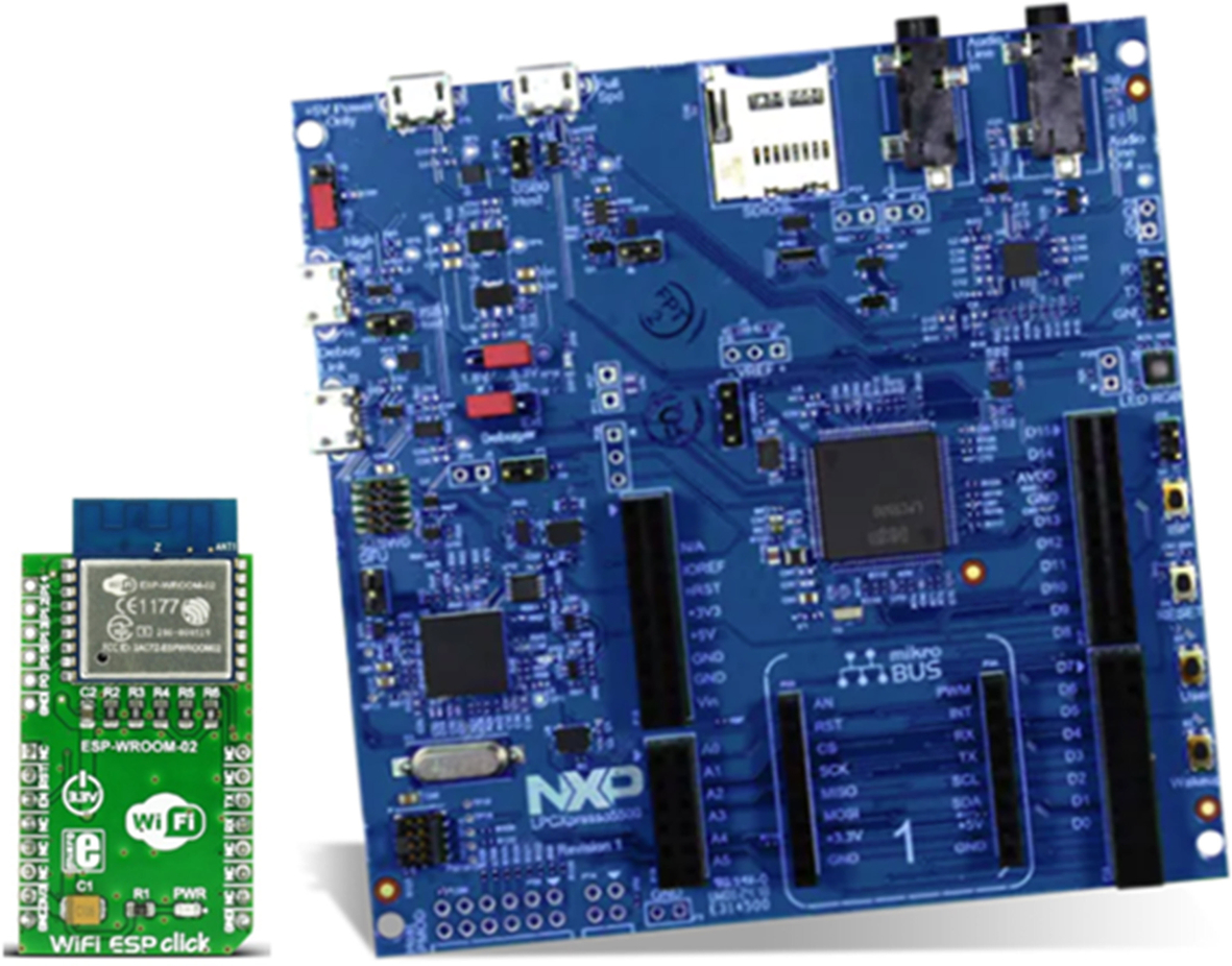
The examples in this book are designed to run on an NXP LPC55S69 XPRESSO evaluation board, which has been fitted with an ESP-Wroom-2 Mikro Click WiFi module and an SD memory card, as shown in Fig. 3.1.
Full details of the hardware are available from the URL’s below:
- https://www.nxp.com/design/development-boards/lpcxpresso-boards/lpcxpresso55s69-development-board:LPC55S69-EVK
- https://www.mikroe.com/wifi-esp-click
The NXP LPC55S69 microcontroller was one of the first Cortex-M33 based microcontrollers available. As we will see in the second half of this book, it contains many security features that complement the Arm Platform Security Model.
Software
To build the examples, we will use the Keil MDK-ARM, which is a reference toolchain for both the CMSIS standards and the Arm Platform Security Architecture.
- • Download the evaluation version of the Keil MDK-ARM using the URL below:
- • Once downloaded run the executable to install the toolchain.
This installs the core toolchain, which includes the Microvision IDE, ArmM Compiler, RTX RTOS, and the Microvision debugger.
Community license
While the MDK-ARM is a commercial toolchain, a community license is available, that allows it to build and debug large projects. This version of the toolchain is to be used for learning projects and other noncommercial projects only.
Full instructions for obtaining and installing the community license are provided on the Tutorial Exercises download page shown below.
Tutorial exercises
All of the exercises in this book are provided as a software pack that can be downloaded from
https://github.com/DesignersGuide/IoT_Security_Examples
- • Download the latest version of the Elsevier.IoT_Device:Security.<version >.pack
- • Once the pack has been downloaded double click on it and it will install using the pack installer utility.
Exercise: Test project
This is a simple project that blinks the user RGB LED. It also writes to a console using the Instrumentation Trace debug channel rather than a hardware USART.
In The Pack Installer select the Boards tab and locate IoT_Device:Security
Now select the examples tab and load the first Example 1.1 Test project by pressing the copy button.
Select a suitable exercise directory and press the OK button (Fig. 3.2).
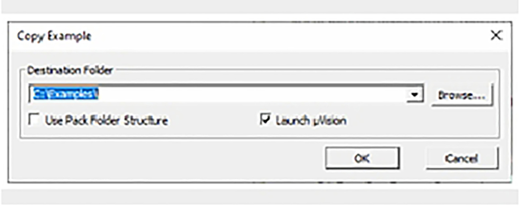
This will copy the blinky project to your hard disk and start the Microvision IDE.
Connect a USB cable to the USB socket labelled Debug Link P6 and a PC USB socket.
Check Jumper J3 is set to the “Loc” position (default).
This connects the debugger and powers the board.
Install MDK packs and utilities
Device support
The Core MDK-ARM toolchain does not include any support for specific microcontrollers. We can add support for specific devices by downloading and installing software packs that are stored in a cloud server. Fortunately, this is easy to do through a built-in pack installer utility.
- Start the Microvision IDE from the desktop icon.
- On the toolbar start the pack installer using the icon shown inFig. 3.3or use projectmanagepack installer.
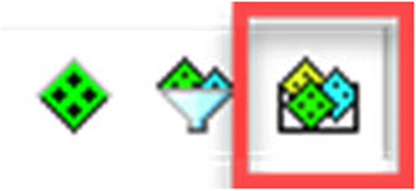
Fig. 3.3 The Microvision Pack installer icon. Within the Microvision IDE, press the pack installer icon. No permission required.
When the pack installer utility starts it will connect to the cloud and update its list of software packs, this may take a few minutes.
- When the pack installer is ready select the device tab (1) and navigate to the NXP/LPC55S69 tree (2) then select the LPC55S69JBD100 (3,4) (Fig. 3.4).
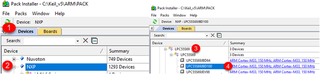
Fig. 3.4 Select the LPC55S69JBD100 microcontroller. In the devices tab, locate and select the NXP LPC55S69JBD100 microcontroller. No permission required.
- In the packs tab (4), install the LPC55S69DFP, device family pack (5), and the LPC55S69 XPRESSO board support pack (6) (Fig. 3.5).
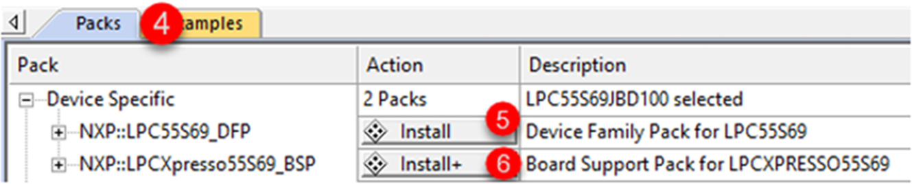
Fig. 3.5 Select the device support packs. In the packs tab, install the device support packs. No permission required.
- We also need to install the following packs that are located in the Pack installer/Packs tab/generic branch (Table 3.1).
Required software packs. Software pack Description ARM::mbedTLS Cryptographic library for Cortex-M devices ARM::mbedCrypto Cryptographic Library for TrustZone Secure Partition ARM:: CMSIS-Driver Validation Test Suite for peripheral drivers based on the CMSIS-Driver specification ARM::TF-M Reference implementation of the PSA Trusted Firmware security services core files Keil::ARM_Compiler STDIO interface files for ARM compiler Keil::LPC55S69xTFM_PF Trusted Firmware platform files for the NXP LPC55S69 family MDK-Packs::AWS_IoT_Device Support files for AWS services MDK-Packs::IoT Socket Simple IP socket implementation MDK-Packs::Paho_MQTT Embedded MQTT client MDK-Packs::CJSON JSON data format parser MDK-Packs::TinyCbor CBOR data format parser Install each of the packs listed in the table.
Additional utilities
In addition to the MDK-ARM toolchain, you will need a terminal emulator. While any should work, the exercises have been tested with Tera Term.
- Download and install Tera Term using the URL below:
The project workspace contains two projects. A fully configured project for reference and a shell project which we will build up to gain some experience with the IDE (Fig. 3.6).
- Highlight the Shell project right click and select “Set as Active Project” (Fig. 3.7).
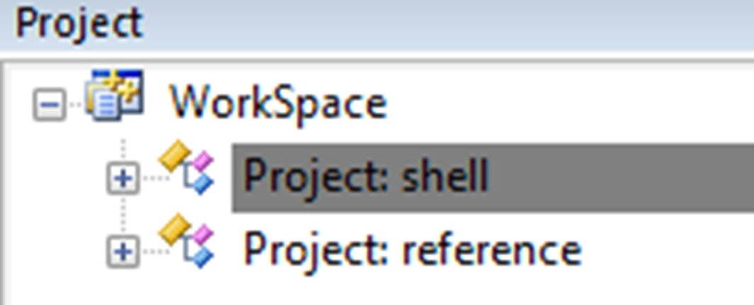
Fig. 3.6 Project workspace. The workspace contains working and prebuilt versions of the exercise project. No permission required. 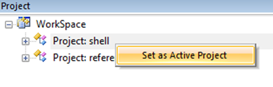
Fig. 3.7 Setting the active project. Select a project and right click to switch active projects. No permission required.
The shell project is an empty project that has been created using the following steps:
- Select project/new project.
- Provide a project name.
- Select the LPC55S69JD100 from the device database.
From this state we can start to expand the shell project by adding software components through a “Run Time Environment” (RTE) manager.
- Open the RTE manager using the green diamond icon (dark gray in print version) on the Microvision toolbar or through Project/Manage/Run Time Environment (Fig. 3.8).
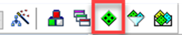
Fig. 3.8 The run time manager toolbar icon. Open the run time manager from the Microvision IDE toolbar. No permission required.
The RTE provides a tree of installed software components that can be added to a project by using the tick boxes in the selection (sel.) column. This dialog allows us to create and manage complex software platforms (Fig. 3.9).
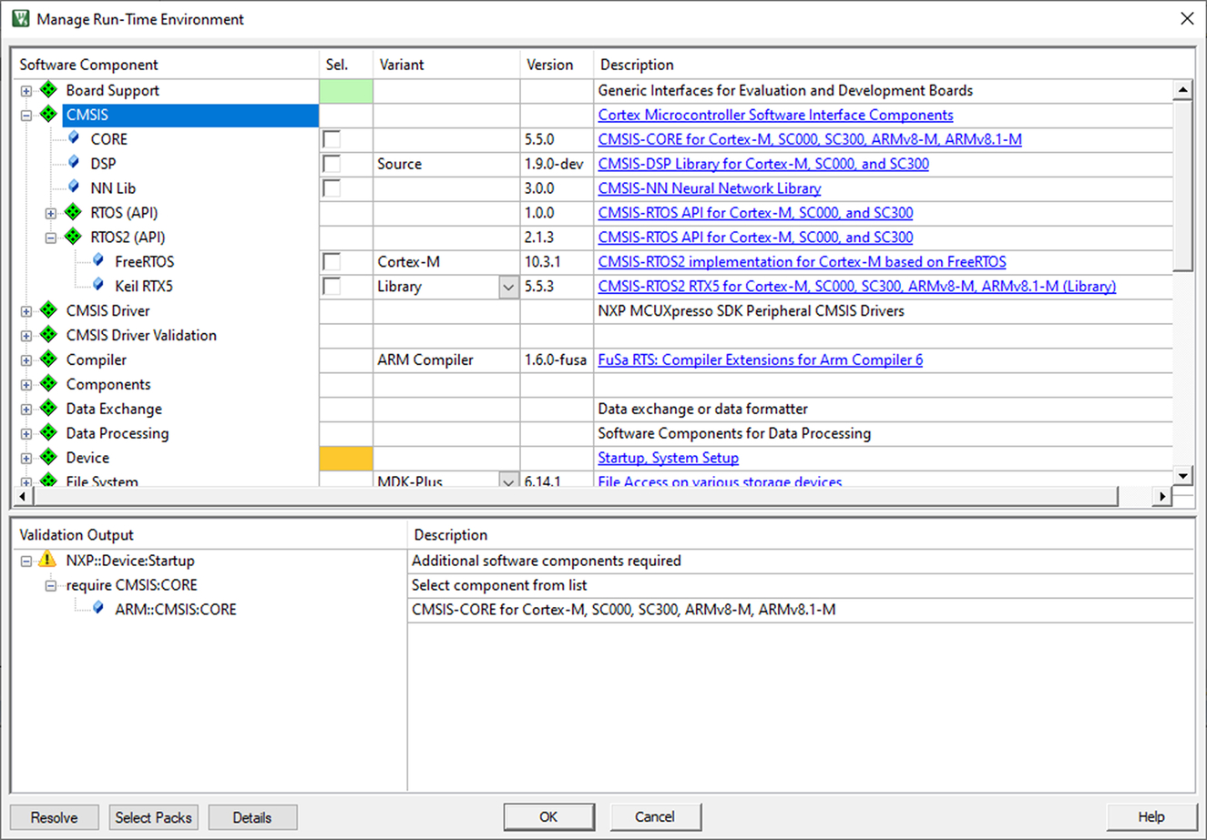
When a selected component has all its necessary dependencies provided, the sel. tick box will appear green. If further options are required, it will appear orange. The validation output window will list the missing files and will show any options available to create a full project. To help this process, RTE also provides a resolve button that can be used to add missing dependencies as far as is possible for the toolchain. Any remaining selections then need to be resolved by the developer. So, for example, you may need to select which low-level peripheral is going to be used with a particular software component.
- In the RTE select Board Support::SDK Project Template::Project Template.
- The template must be set to lpcxpresso55S69 (1).
- Press the resolve button to add the supporting components.
- Add the following additional components (Fig. 3.10).
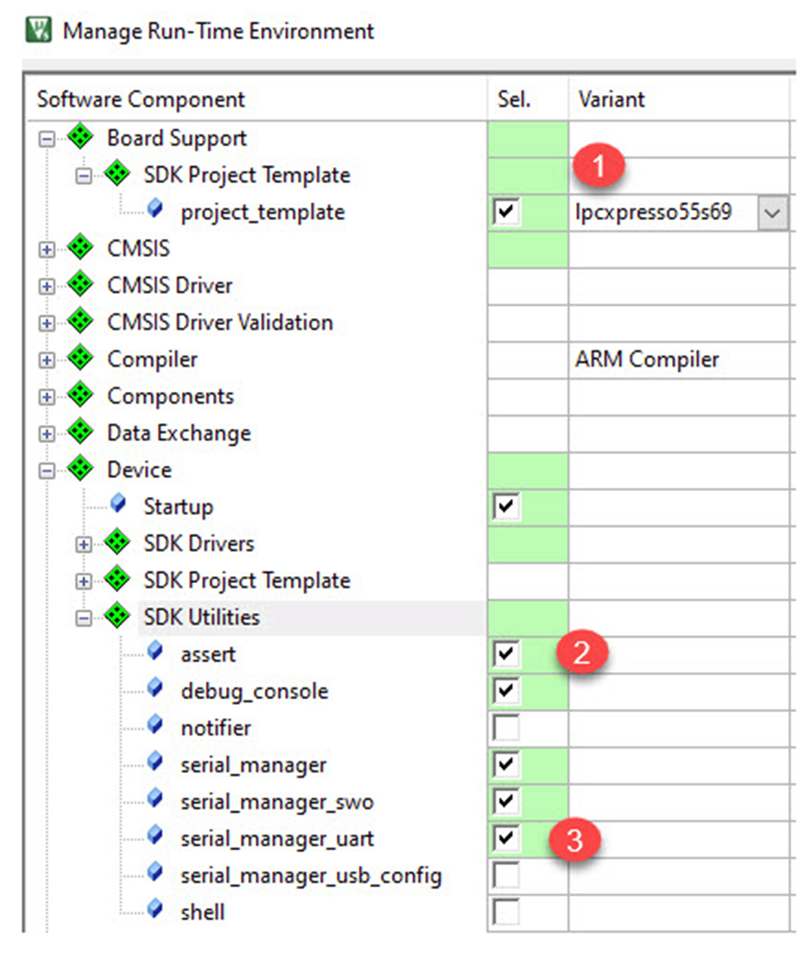
Fig. 3.10 RTE component selection. Add the core project components, dependency files may be added by pressing the resolve button. No permission required.
Device::SDK_Utilities::assert (2)
Device::SDK_Utilities::Serial Manager_uart (3)
- Open the CMSIS branch and add the Core support
This sets a path to the CMSIS-Core support files, which are then included by the device header file.
- Open the RTOS2 branch and select the Keil RTX5 (Fig. 3.11).
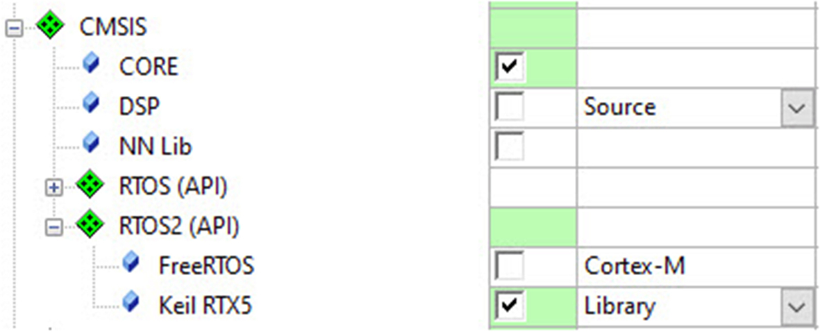
Fig. 3.11 Add the project components. In addition to the test framework, we must also add the CMSIS—Core and CMSIS RTOS2 components. No permission required.
This adds a small footprint RTOS, which will be used in most of the examples in this book.
- All the selected entries in the sel. Column should be green, if not use the validation window to resolve any missing components.
If this is not the case check the reference project for the correct settings.
- Now click OK to add the components to the project.
The software components will be added to the project, as shown in Fig. 3.12.
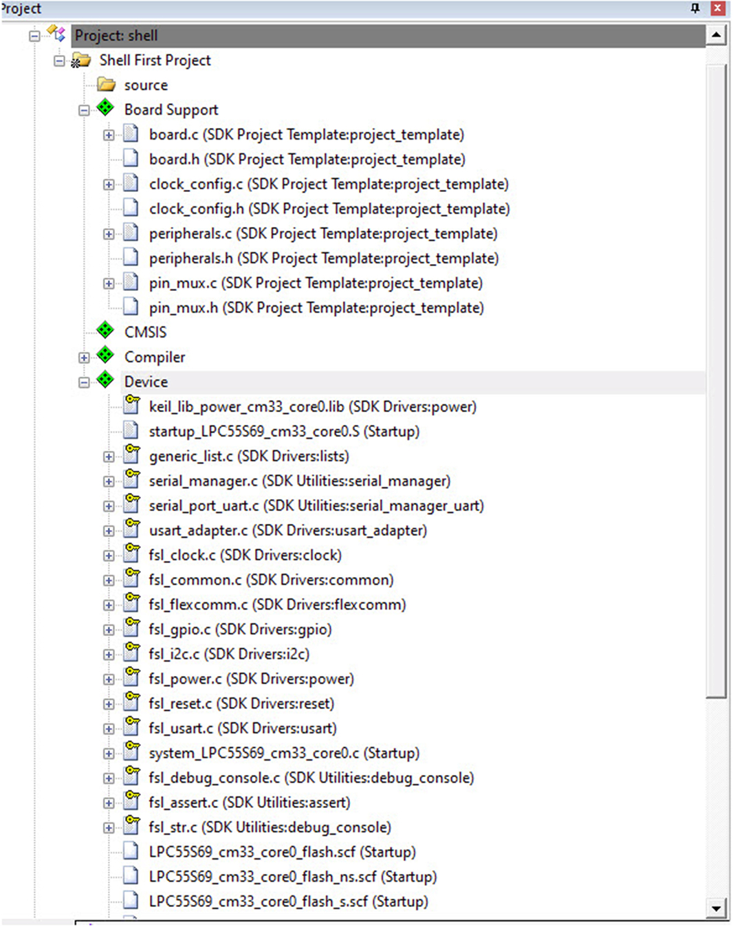
In the project window, the component branches are shown with a green diamond (dark gray in print version) and the user source code branches are shown as a file folder.
Within the Software component branches, the source code is held in the pack repository as read-only files. The write protection is shown as a yellow key icon (light gray in print version).
Any configuration options are held in read/write header or source files which have _config as part of their name.
Most of the configuration files can be viewed through a configuration wizard, which is enabled through a tab that is located bottom left of the editor window (Fig. 3.13).

The final image layout is controlled using a linker scatter file. These files have the extension .scf. Several scatter files are provided for different build configurations. In this project, we are using the LPC55S69_cm33_flash.scf, which defines a basic image layout for the internal flash memory.
- Highlight the project root (Shell First Project), right click, and select “Options for Target” (Fig. 3.14).
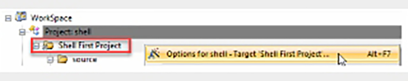
Fig. 3.14 Selecting the global project options. Select the root project, right click, and select "Options for Target" to open the global project options. No permission required.
This view contains a set of dialogs that hold all the global project options.
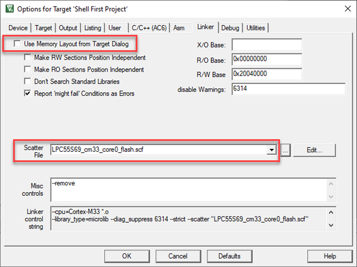
- Select the linker tab.
The default memory layout has been disabled, and instead, the linker will use our custom linker scatter file (Fig. 3.15).
Have a look through the other dialogs but for now don’t change any options.
- Click ok to close the options for target window.
- Select the source folder.
- Right click and select add existing file (Fig. 3.16).
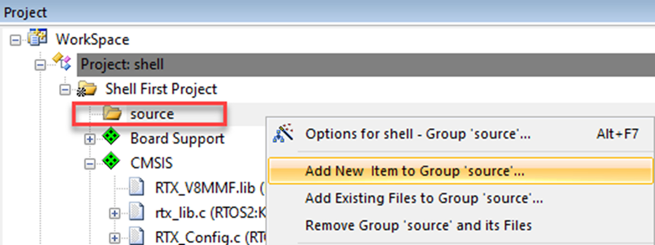
Fig. 3.16 Adding a project file. Select the source folder, right click, and select "Add existing file." No permission required.
- Navigate to the < example >/ directory.
- Add the following “hello_world.c” file.
- Click OK to finish.
- Build the project using project/build Target (F7) or the toolbar icon.
- Select debug/start | stop (Ctrl + F5) or the toolbar icon.
This will download the image to the target FLASH and run the code to main.
- Select Debug run (F9) to Run the code.
Explore the debugger toolbar using the options shown below.
You can set a breakpoint by clicking on the dark gray boxes next to the source code (Fig. 3.17).
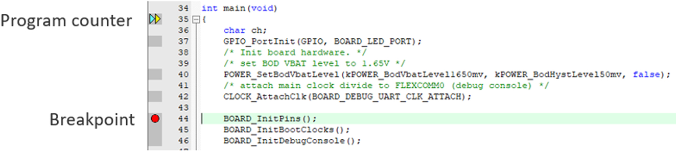
A breakpoint is shown as a red dot (dark gray in print version).
- The configuration of each peripheral is shown in the Peripheral/System Viewer menu (Fig. 3.18).
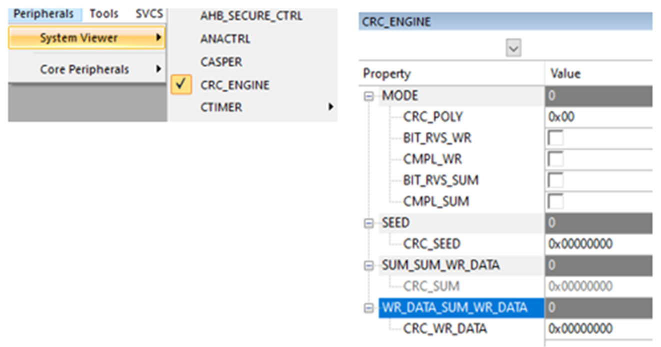
Fig. 3.18 Peripheral view window. The microcontroller peripherals are displayed in custom windows. No permission required.
The state of the RTOS can be seen in a similar component viewer window.
- Select the ViewWatch WindowsRTX RTOS item (Fig. 3.19)
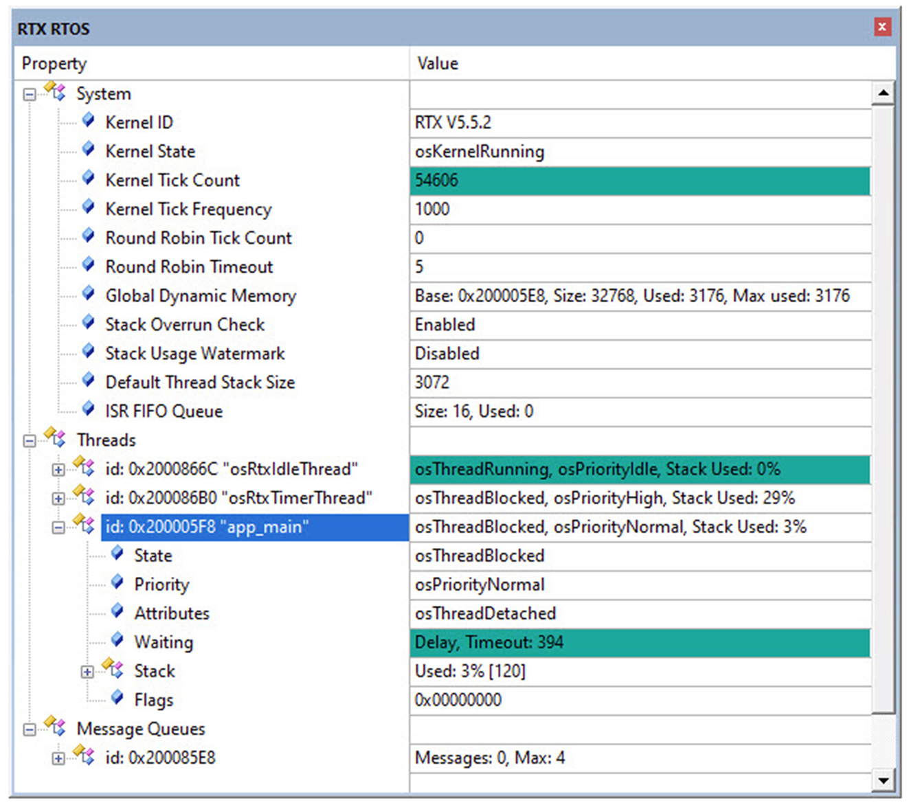
Fig. 3.19 Microvision project workspace. The RTE adds the board support and device driver library files to the project workspace. No permission required.
The code will also enable the debug "Serial Wire Out" SWO pin, which allows the debugger to use the Instrumentation Trace and Data Watch Trace, which are part of the Cortex-M Coresight debug architecture.
- Start Tera Term
This will launch the new connection dialog.
- Enable the Serial option and select the LPC-LinkII U Com Port (Fig. 3.20)
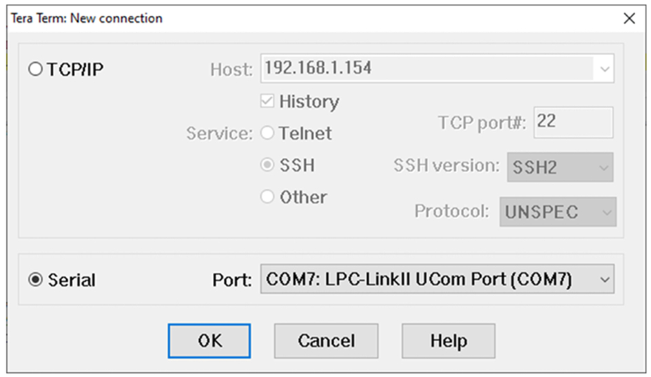
Fig. 3.20 Tera Term connection dialog. Enable the serial option and select the LPC-LinkII virtual serial port. No permission required.
The Cortex-M33 debug architecture contains an “Instrumentation Trace.” This provides a serial interface from the processor to a serial terminal via a virtual serial port created by the built-in debug hardware on the Xpresso evaluation board. Now within our code, STDIO used by printf and scanf will be redirected to the Tera Term console.
- Select setupserial port and set the baud rate to 115200 (Fig. 3.21)
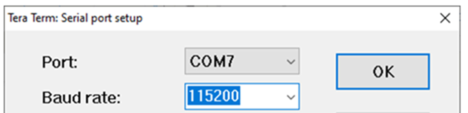
Fig. 3.21 Tera Term serial configuration. In the serial port menu, set the baud rate to 115200. No permission required.
- Return to the debugger reset the code and start the application code running.
- Observe the diagnostic messages printed to the terminal (Fig. 3.22).
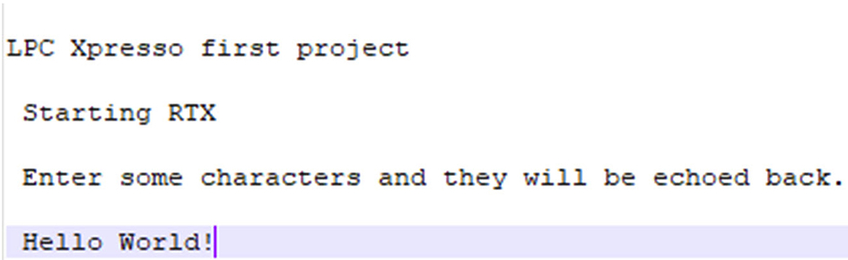
Fig. 3.22 Microvision project workspace. The RTE adds the board support and device driver library files to the project workspace. No permission required.
This will execute the code and display a startup message on the Tera Term console. You can now type characters within Tera Term and they will be echoed back the RGB LED is toggled on and off as each character is typed.
The default terminal window in Tera Term is white text on a black background. In this book, the display has been transposed to black text on white for better printing results.
This example should have familiarized you with the MDK-ARM toolchain and help prove out the hardware. Before we leave this exercise, it is worth noting one more thing:
How to get out of jail free
If you are experimenting with this board, you may do something that locks up the microcontroller preventing the debugger from connecting. Typically, this can occur if you add low power code or miss configure the processor clock tree.
If you get into this predicament, it is possible to erase the internal FLASH by holding down the ISP button and then powering the board. This will start the internal bootloader running rather than the FLASH code. You should then be able to connect the debugger and erase the FLASH memory. This will recover the board, and you can continue.
The LPC55S69 contains a PSACertified compliant secure boot ROM, and we will have a detailed look at this later. Needless to say, this technique does not work if the secure boot has been enabled. You have been warned!
CMSIS WiFi driver
The CMSIS WiFi driver is designed to provide a common interface to supported WiFi “System on Chip” SoC devices. Currently, the following devices are supported (Table 3.2).
| Device | Interface | Data bypass mode |
|---|---|---|
| ESP32 | UART | No |
| ESP8266 | UART | No |
| ISM43362 | SPI | No |
| WizFi360 | UART | No |
| QCA400x | UART/SPI | Yes |
The CMSIS WiFi driver is a compound driver that uses a further CMSIS driver for low-level communication to the module. This will typically use an SPI or USART as the module interface (Fig. 3.23).
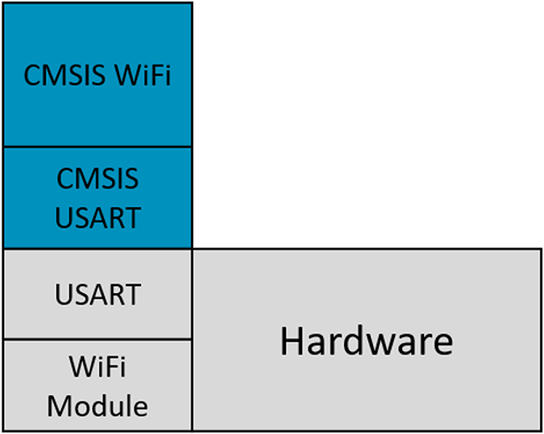
Each WiFi module contains its own TCP/IP stack. This allows the module to manage all network communications while providing a socket interface for the microcontroller. However, WiFi modules often have limitations in the size of IP packets they can send and receive. Many IoT devices only need to transfer relatively small amounts of data, so this is not usually a problem, but it is something to bear in mind when selecting a module. If the module supports “Data Bypass Mode,” the onboard TCP/IP stack can be replaced by a TCP/IP stack such as LwIP or the Keil network component running on the application microcontroller. This removes many of the modules limitations and allows us to develop a wider range of more sophisticated network applications.
We can add WiFi support to our project through the run time environment manager. Since we are configuring two CMSIS drivers which are acting in concert, we need a methodical way of configuring and testing the drivers with minimal effort. Fortunately, the CMSIS WiFi driver is well supported within the CMSIS driver validation suite, and this provides an ideal way to bring up the driver for the first time.
Exercise adding WiFi support
In this exercise, we will set up a module that uses a UART interface and then have a look at the more complex configuration for a module with an SPI interface.
- In the pack installer select Example 1.2 WiFi Module and press the copy button.
This is a multiproject workspace with a fully configured project for reference and a shell project, which we will use to add and test the CMSIS drivers.
- Set the shell project to be the active project.
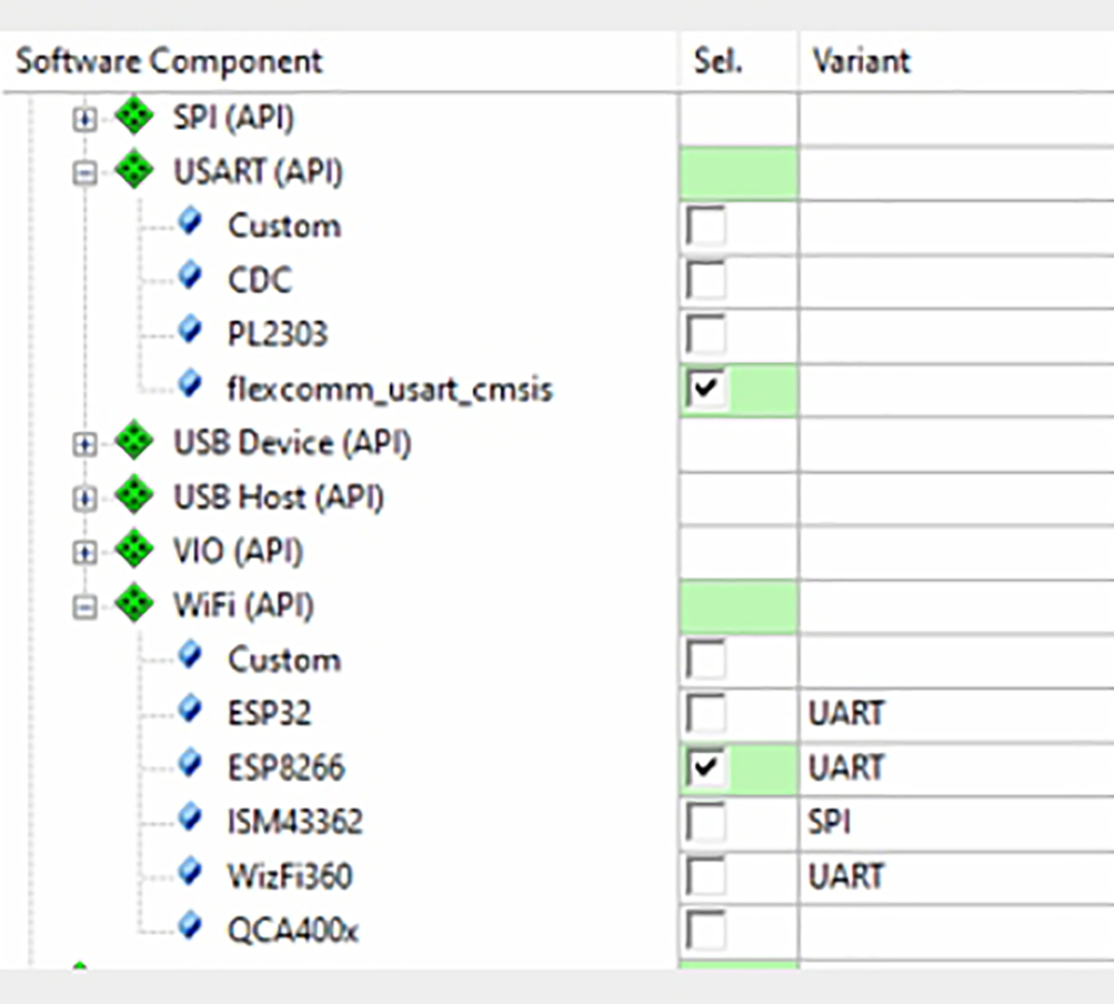
- Open the manage run time environment and select the CMSIS DriverWiFiESP8266.
This module uses a UART interface, so we also need to add a CMSIS USART driver. In this case, we need to add support for a plain hardware USART, which is supported by the CMSIS DriverUSART(API)flexcomm_usart_cmsis driver (Fig. 3.24).
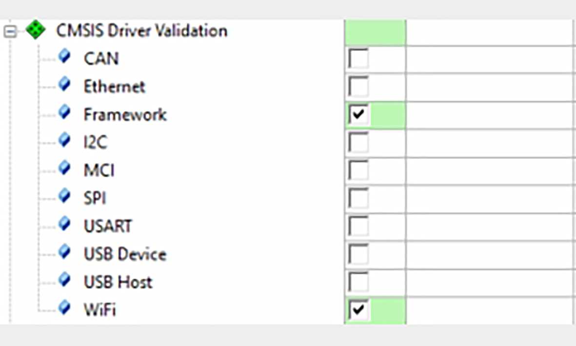
Next, we need to add to the CMSIS driver validation framework.
- In the RTE, open the CMSIS Driver validation branch and select the framework and add the WiFi options.
If you have new or unknown hardware you could also add the USART validation tests (Fig. 3.25).
The validation framework is designed to run bare metal or with the CMSIS RTOS2. In this exercise, we will need to add the RTOS as well.
- Add the RTX5 RTOS in CMSISRTOS2(API)RTX.
- Set the variant column to library (Fig. 3.11).
Depending on your installation, you may have several RTOS choices available. In this book, we are going to use the Keil RTX5 RTOS as this has a small footprint and native support for the CMSIS-RTOS2 API.
- The validation framework sends test results to the debugger console window in either a text or XML format.
- Resolve any dependencies and then click OK to add the driver files to your project.
Now we can use the configuration wizards to setup the CMSIS drivers and validation framework.
First, select the DeviceRTE_Device.h file and enable the UART, which will be used to communicate with the WiFi module. As we are using the LPC55S69 expresso board, this will be UART 2.
- Open deviceRTE_Device.h and set RTE_USART2 to “1” as shown inFig. 3.26.
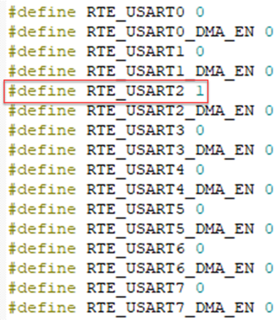
Fig. 3.26 USART selection. USART 2 is used to communicate with the WiFi module. No permission required.
- Next select the CMSIS DriverWiFi Config.h (Fig. 3.27).
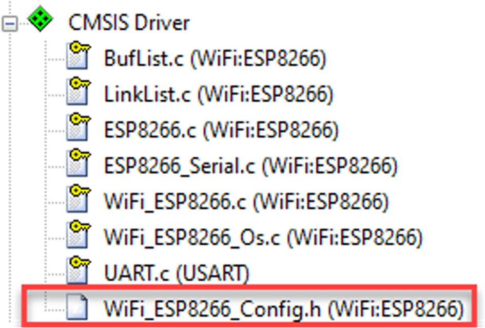
Fig. 3.27 CMSIS WiFi configuration file. The CMSIS WiFi driver options are all in the module config.h file. No permission required.
For initial testing, use the default settings, but we do need to adjust the USART driver number to match the hardware configuration on the Xpresso board. In this case, the USART driver value must be set to “2.” We must also allocate 1024 bytes to the WiFi driver RTOS thread (Fig. 3.28).
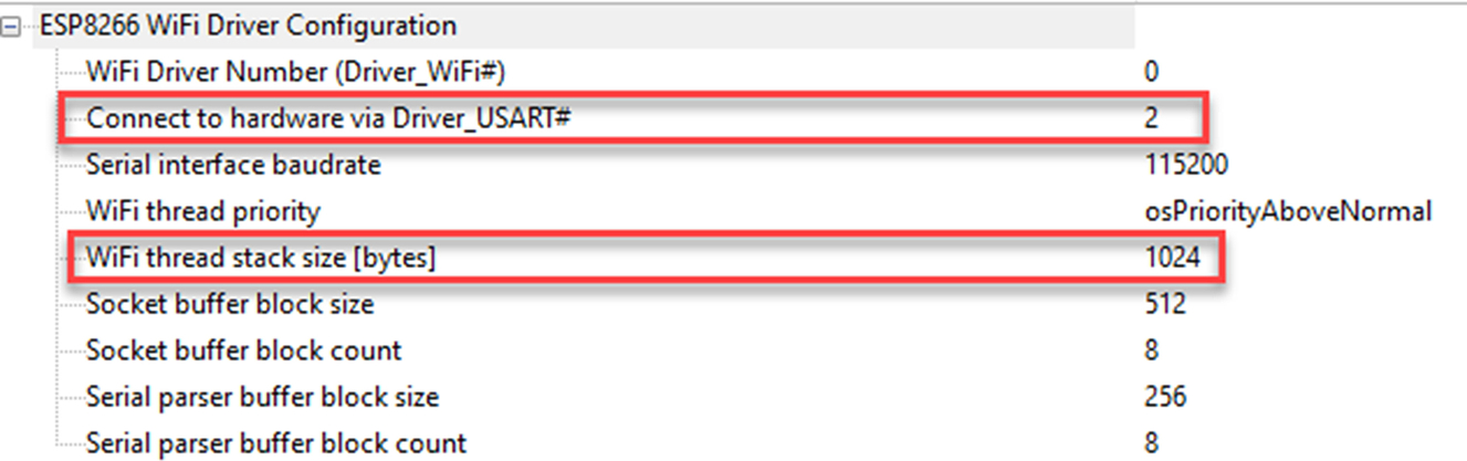
The WiFi driver will configure the CMSIS USART driver so we have nothing further to do at the USART driver level.
To configure the validation environment, we need to setup the RTOS and debug components.
- Select the CMSISRTX_Config.h file (Fig. 3.29).
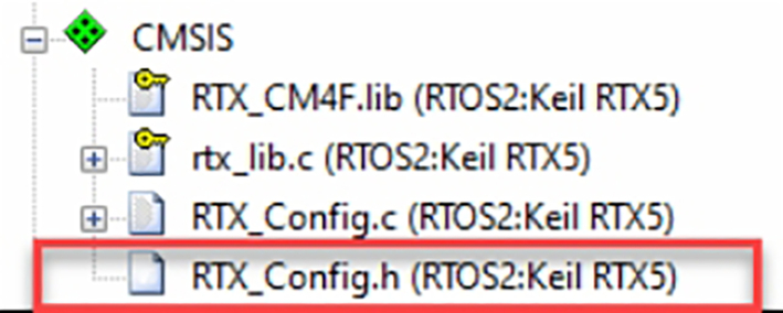
Fig. 3.29 The RTX RTOS configuration file. The RTX_Config.h file contains all the RTOS configuration options. No permission required
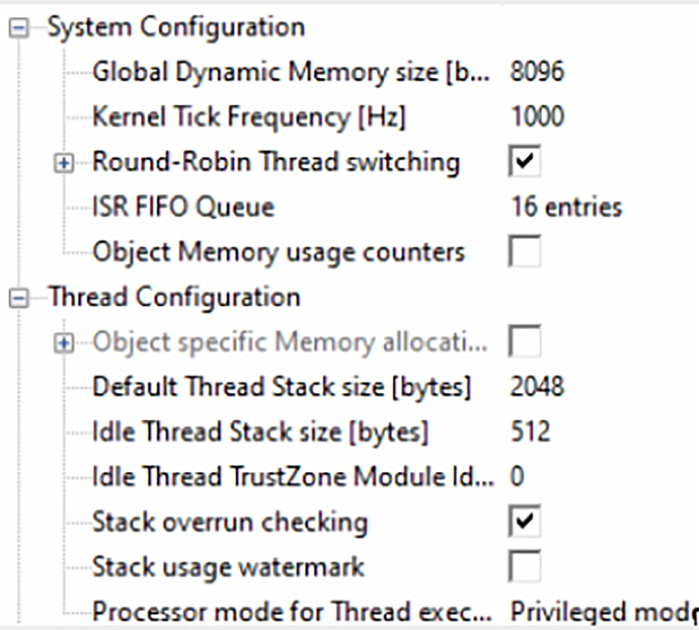
Here, we must have a global memory pool of at least 8096 bytes and a default thread stack size to 2048 bytes (Fig. 3.30).
Now we can configure the validation framework in dv_config.h header. The first section allows us to set the global framework options. For this test, we can again use the defaults with the print output format set to XML for the final report.
- Open CMSIS Driver ValidationDV_Config.h and select the wizard
- Select an output format you want to work with either plain text or XML (Fig. 3.31)
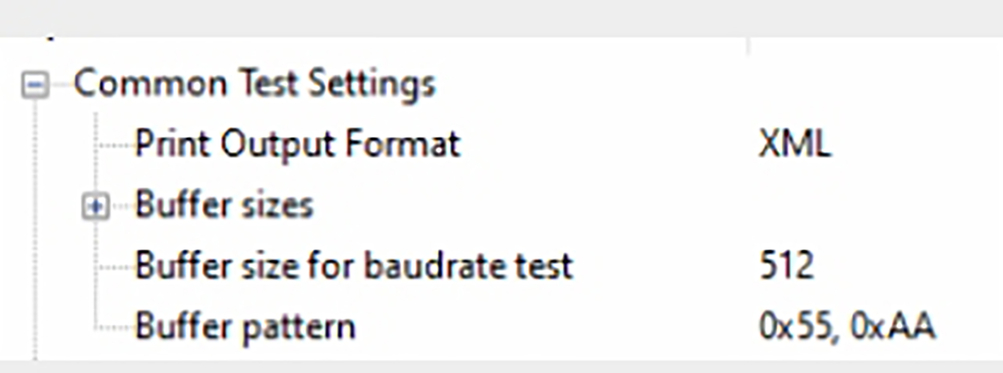
Fig. 3.31 CMSIS driver framework wizard. We can set the test report format in the validation framework wizard. No permission required.
Open CMSIS Driver ValidationDV_WiFi_Config.h and select the wizard
- The configurationstation section needs to be configured with the SSID, password, and security type of your WiFi access point (Fig. 3.32).
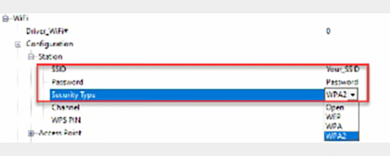
Fig. 3.32 CMSIS WiFi test suite configuration wizard. Set you WiFi network SSID password and security type. No permission required.
During the validation tests, data packets will be sent to a “socket server” running on a network PC. The socket server is a dedicated executable that is designed to run in a Windows environment. The socket server is located in the following directory:
- C:Keil_v5ARMPACKARMCMSIS-Driver_Validation<version >ToolsSockServerPCWin
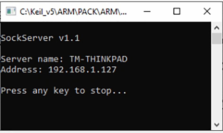
As this may change I have also included the socketserver executable in a folder within the current example. The socket server is an executable, which just needs to be started without any further configuration. However, you will need to create an exception rule in your firewall to allow a remote device to connect. Once started, its IP address will be displayed on the console screen (Fig. 3.33).
The socket server provides a number of testing services that are used by the CMSIS driver validation suite. Each service supports both TCP and UDP protocols (Table 3.3).
- Start the socket server on a network PC.
- Make a note of the PC IP address shown in the socket server console window
- Then update the PC socket server IP address in the WiFi validation configuration header (Fig. 3.34).
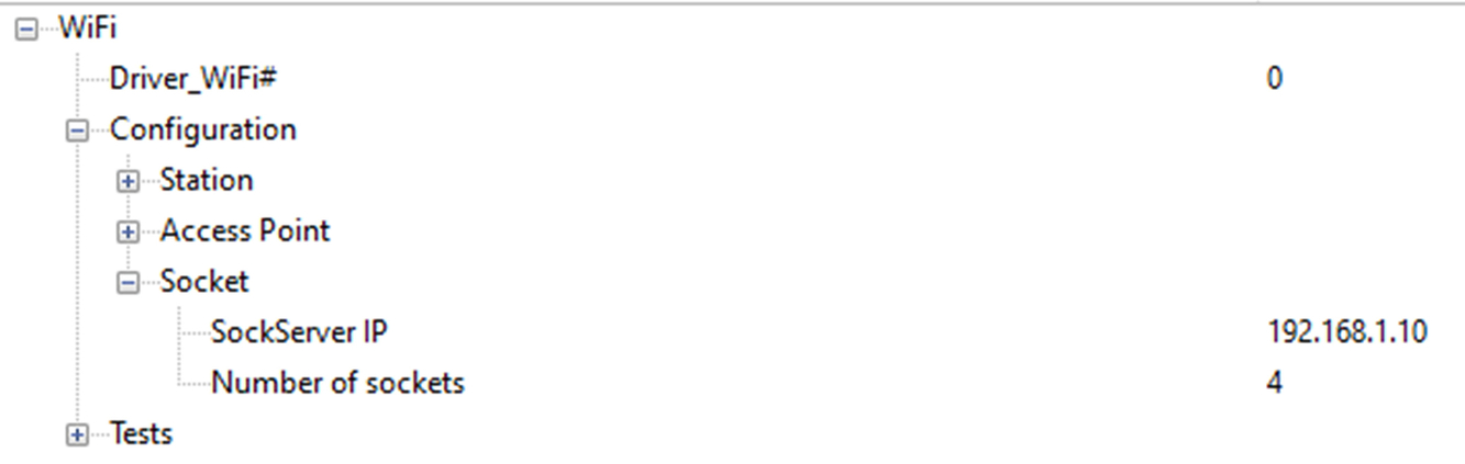
Fig. 3.34 WiFi test suite configuration wizard. Set the socket server IP address in the DV_WiFi_Config.h configuration wizard. No permission required.
| Service | Port | Description |
|---|---|---|
| Echo | 7 | Echo’s back received data packets |
| Discard | 19 | Accepts remote socket connection |
| Chargen | 19 | Send continuous character stream |
| Assistant | 5000 | Connects to remote server socket |
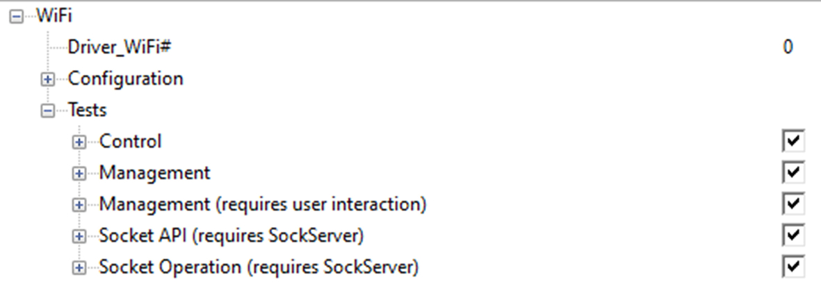
The final section of the validation configuration wizard allows us to enable a wide range of tests for both the WiFi module features and communication. For initial testing, we can use the default test settings, and this will exercise most of the driver features (Fig. 3.35).
Once the driver and test framework are configured we can invoke the test framework from main() as follows:
#include "cmsis_dv.h" #include "cmsis_os2.h" int main(void) { SystemCoreClockUpdate(); osKernelInitialize (); //app_initialize(); osKernelStart(); /* Start thread execution */ while(1); }
This code is provided in a module main.c located in the project directory.
- Open main.c in the project window to view the validation code.
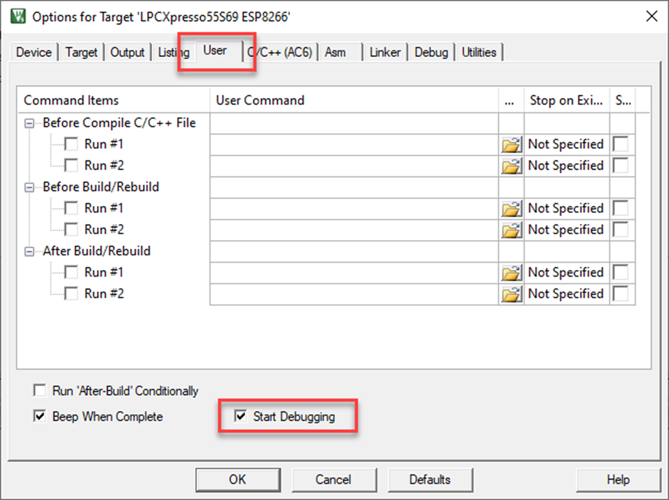
Compared to a normal development project, there are a couple of settings that can be used to make this project a more efficient test environment. First, the project is configured to start the debugger after a build by setting the “Start debugging” option in the Options for target/User dialog (Fig. 3.36).
A script file has been added to the debugger dialog, and the script will execute when the debugger is started. This is very important as this “automates” the build and test loop, which can then be executed with a single button press (Fig. 3.37).
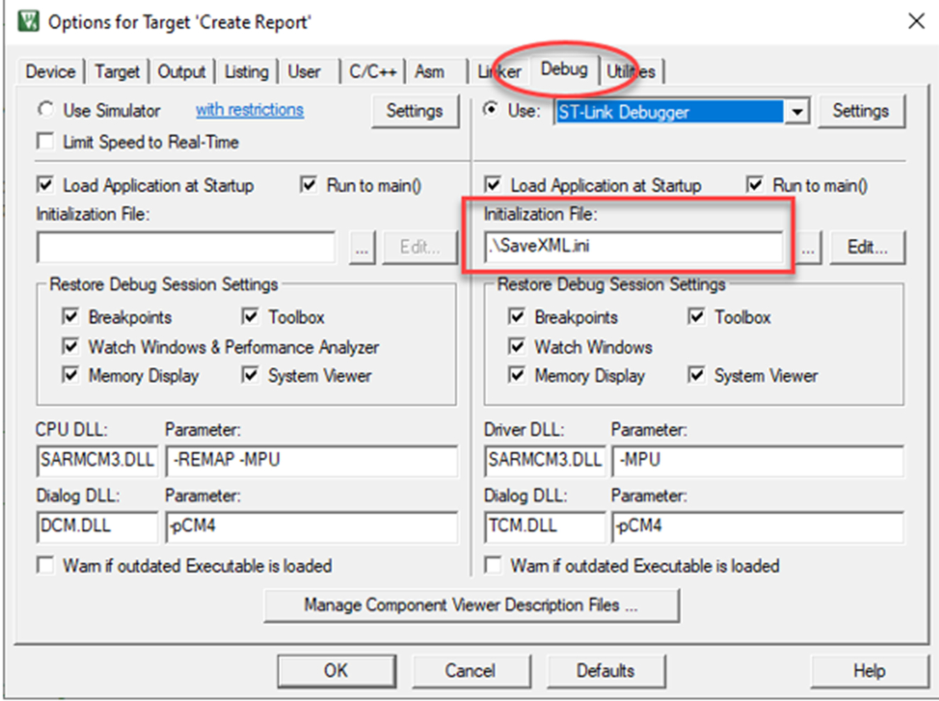
The script file controls execution of the test framework and logs the test results to a file in the project directory. When XML format is selected, a schema is also saved.
When using a standalone debug adapter such as Ulink or Jlink, the test results can be displayed in a console window in microvision. The SLOG command can be used to store the results in a file automatically.
- Now build the project and execute the validation tests.
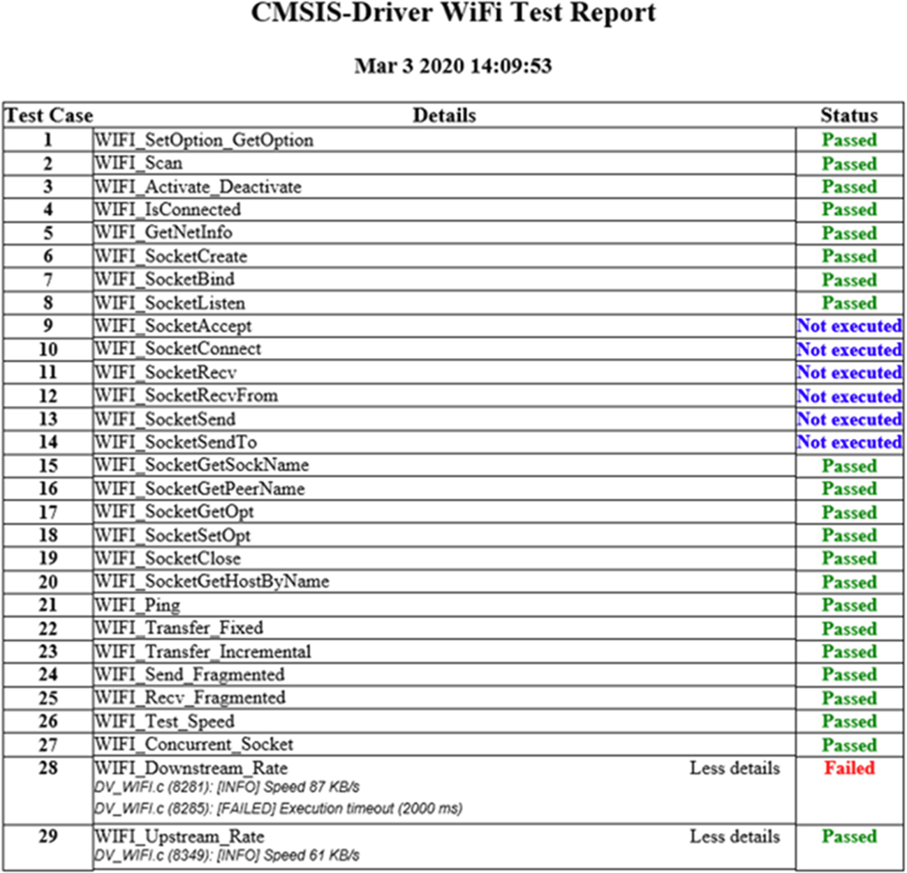
The validation tests report can be copied from the Tera Term console and saved to a file in the project directory. This file can then be viewed with a HTML browser (Fig. 3.38).
SPI interface
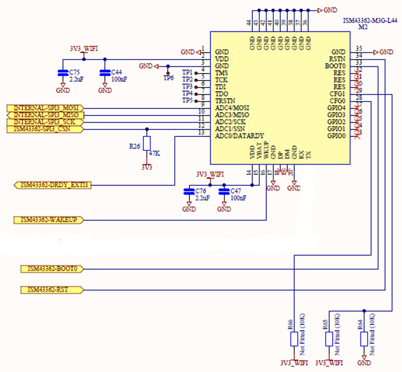
If the WiFi module has an SPI interface, it will include a slave select line, which must be managed at the start and end of communication from the MCU. Since the SPI interface is synchronous, the module uses a “Data_Ready” line to signal the MCU that data are ready to be read from the WiFi module. The data ready line should be connected to an MCU GPIO pin that can generate an interrupt when the data ready line becomes active (Fig. 3.39).
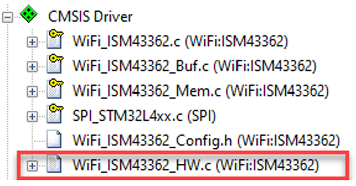
The driver for SPI based modules provides an extra hardware interface file that contains stub functions that allow these features to be managed by the MCU GPIO pins (Fig. 3.40).
The MCU GPIO pin connected to the data ready line should be configured to trigger when the data ready line becomes active. Its interrupt function can then signal the driver that new data are ready using the function provided as shown below:
- void GPIO_External_Interrupt(void){
- WiFi_ISM43362_Pin_DATARDY_IRQ();
- }
The hardware interface file contains stub functions to control the MCU GPIO pins connected to the reset line and slave select lines.
void WiFi_ISM43362_Pin_RSTN (uint8_t rstn) { GPIO_WritePin(GPIOE, GPIO_PIN_8, rstn ? GPIO_PIN_RESET : GPIO_PIN_SET);} void WiFi_ISM43362_Pin_SSN (uint8_t ssn) { GPIO_WritePin(GPIOE, GPIO_PIN_0, ssn ? GPIO_PIN_RESET : GPIO_PIN_SET); } uint8_t WiFi_ISM43362_Pin_DATARDY (void) { return (GPIO_ReadPin(GPIOE, GPIO_PIN_1) == GPIO_PIN_SET); }
Once the hardware interface file is configured, you can test the driver as shown in the previous example.
Using the WiFi module
Once the WiFi driver has passed the validation tests, we can remove the validation framework and access the driver from our application code.
Open the RTE and remove the CMSIS validation framework options and click OK
In the project window, open main.c
- Remove the validation header file
- Remove the device validation new thread call
osThreadNew(cmsis_dv, NULL, NULL);
- Uncomment the start of the application code
- Open the file socket_startup.c
- Enter your WiFi SSID and password into the #define strings in this file.
- #define Your_SSID “”
- #define Your_Password “”
The app_main thread will be used to first initialize and power up the WiFi module using the socket_startup() function
- void socket_startup (void){
- ARM_WIFI_CONFIG_t config;
- Driver_WiFi0.Initialize (NULL);
- Driver_WiFi0.PowerControl(ARM_POWER_FULL);
The code will then activate the WiFi module so that it attempts to connect to the network. If this is successful, we can run a main application that will be able to send and receive TCP/IP packets using the WiFi module.
- config.pass = "Your_Password";
- config.security = SECURITY_TYPE;
- config.ch= 0U;
- Driver_WiFi0.Activate(0U, &config);
- if (Driver_WiFi0.IsConnected() == 0U) {
- printf("WiFi network connection failed! ");
- } else {
- printf("WiFi network connection succeeded! ");
- }
- return 0; }
File system
The project also contains a port of the FATFS file system, which can be used to read and write files to an SD card that has been inserted into the SDIO socket on the evaluation board.
Once the WiFi module has been connected to the local network, the application code will initialize the file system and create a test file on the SD card.
- Place an SD card in the card holder on the Xpresso evaluation board.
The code will now initialize the file system and create a test file on the SD card.
- Remove the SD card, insert it in a card holder, and place it in your PC.
You should now be able to view and read the test file on your PC to check that the file system is working.
Conclusion
We now have our evaluation board set up with a WiFi interface to a local network that allows us to send and receive TCP packets through a socket interface. We can also build applications with a professional toolchain and debug them on the evaluation board. Over the next two chapters, we will look at building a secure communications channel that can be used by our IoT devices to communicate with a cloud server.