Chapter 9: Building a defense with the PSA security model
Abstract
In order to meet the threat of a software attack, the Platform Security Architecture (PSA Certified) defines an abstract security model that can be applied to any Cortex-M processor. This chapter will provide an introduction to the security model and its objectives. In the rest of this book, we will see how to implement this model using a Cortex-M33 microcontroller. The PSA security model defines 10 security goals required to create a robust IoT device.
Keywords
PSA security model; IoT device; Cortex-M33; Immutable RoT; Boot seed; Encryption; Secure execution environment; Nonsecure environment
Introduction
In order to meet the threat of a software attack, the Platform Security Architecture (PSA Certified) defines an abstract security model that can be applied to any Cortex-M processor. This chapter will provide an introduction to the security model and its objectives. Then in the rest of this book, we will see how to implement this model using a Cortex-M33 microcontroller. The PSA security model defines 10 security goals required to create a robust IoT device, as shown in Table 9.1.
| Goal number | Requirement |
|---|---|
| 1 | All devices must be uniquely identifiable |
| 2 | All devices must support attestation |
| 3 | Application data and secrets must be bound to a given device and its security configuration |
| 4 | All devices must support a Secure Boot process to ensure that only authorized software can run on the device |
| 5 | Software isolation must always be provided |
| 6 | A secure update process must always be provided |
| 7 | All updates must be validated before being installed |
| 8 | A device must prevent unauthorized rollback of software updates |
| 9 | All devices must support a security life cycle and the current state of a device must be attestable |
| 10 | All devices must impediment a generic cryptographic service at the most trusted level of the system |
The PSA security model defines 10 mandatory requirements.
In order to meet these goals the PSA security model defines four strategies:
- Software architecture
- Device lifecycle
- Trusted security services
- Secure Boot with a firmware update client.
While these are presented as abstract definitions in the security model, they provide a structure and terminology that is useful for implementing a real-world solution.
Software architecture
When we develop code for a microcontroller, we are used to developing a single application image that is built within a single IDE project. In contrast, the PSA security model defines a tier of processing environments, as shown in Fig. 9.1.

You can interpret “processing environment” to be a self-contained executable image and associated IDE subproject. This means that our final application will be constructed as a set of interdependent subprojects. During the boot stage, the aim of the security model is to establish a secure Root of Trust (RoT), which can be used to validate each of the executable software components within the device. The Root of Trust will also provide a unique immutable identity for the device. Once we are past the initial boot stage and the RoT is established, the microcontroller resources are divided into two execution environments or partitions, as shown in Fig. 9.2.
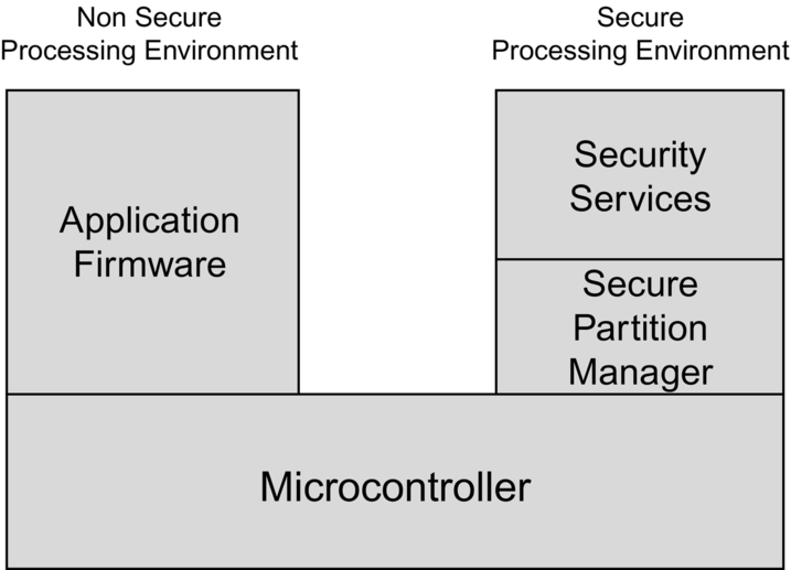
The first partition creates an execution environment for the application code called the Non-Secure Processing Environment (NSPE). The second partition is a separate environment for the sensitive security functions called the Secure Processing Environment (SPE). The NSPE and the SPE are isolated from each other, so that code in the NSPE cannot see any data or code in the SPE. The NSPE can access SPE functions by using a well-defined API to make calls across the isolation boundary. In practical terms, the application code runs like a standard image and is assumed to be vulnerable to a software attack. However, all of the device secrets are located in the SPE. They are used only within the SPE and are never directly exposed to the NSPE. This allows the NSPE to pass data to the SPE where, for example, it may be encrypted using a provisioned secret key, and the encrypted data are then returned to the NSPE. If the NSPE does get compromised, there is still no way to access device secrets stored in the SPE.
The different processing environments that make up the security model are separated by either “temporal barriers” or “runtime isolation” through partitioning.
Temporal barrier
The PSA boot process consists of several stages. As each stage executes, it runs as a single-threaded application and then passes control to the next stage. This shift from one execution environment to another is termed a temporal barrier. The new processing stage cannot see the contents of the previous stage data except for a defined state which is passed across the temporal barrier. This state is a collection of measurements that consists of the device ID, image hashes, and firmware version numbers. In order to keep the overall code footprint low, software components that are used in the boot process may be reused by the main application code. In more familiar microcontroller scenarios, the initial boot stage consists of a ROM first-stage bootloader, which passed control to a separate second-stage bootloader stored in FLASH memory.
Runtime isolation
After we have passed through the temporal barriers, the code will be divided into two different processing environments: the SPE and NSPE. The PSA security model requires that they are fully isolated from each other. The PSA security model suggests a number of different isolation methods. The most common methods used with a standard microcontroller are outlined below.
Secure element
A secure element is an additional standard device that contains firmware that can provide cryptographic services to the main processor and acts as a “vault” for device secrets and certificates. A secure element is often interfaced to a microcontroller via a serial interface such as SPI and has a well-defined protocol that defends against software attacks launched via a compromised host microcontroller. A distinguishing feature of a secure element is that it can run its own application software such as payment transactions.
Trusted Platform Module (TPM)
A TPM is very similar to a Secure Element, but it differs in that it cannot run its own applications and acts as a coprocessor to the host microcontroller to provide security services. A TPM can also be used to securely store values calculated by the host processor. For example, the TPM may store measurements (hashes) of images calculated during a Secure Boot process.
Dual core microcontroller
Both the Secure element and the Trusted Platform Module are additional external components and carry a cost in both silicon and board space. It is possible to implement separate processing environments using a dual-core microcontroller. Such devices often feature a Cortex-M4 or Cortex-M7 as the main processor, with a Cortex-M0 as the secondary processor. Using such a device would allow the Cortex-M4 to be used as the application processor while the Cortex-M0 is used as the security processor. For this approach to work, the system resources must be rigidly divided between the two processors. We would also need to define a message-passing protocol that allows communication between the two CPUs. While this does create a secure and Non-Secure Processing Environment, it has a large design overhead of a custom proprietary approach, which must be maintained along with the application code.
Trusted Execution Environment
We can create a Trusted Execution Environment within a single core microcontroller. In this model, the processor resources are divided to create a secure and nonsecure partition. This allows secure code to execute in isolation from the nonsecure partition and provide secure services to the main application boundary. Depending on the Cortex-M processor we are using, there are two main ways to create a Trusted Execution Environment.
Single core Armv6/7-M microcontroller
It is possible to implement a Trusted Execution Environment within an Armv7-M-based microcontroller using a mixture of hardware and software. In this scheme, the MPU would be used to manage an access policy across the regions, and a secure hypervisor or microVisor would be used to manage software calls across the partition.
Single core Armv8-M microcontroller
The latest generation of Cortex-M processors, Cortex-M23/33 and M55, features an optional security peripheral called TrustZone that allows you to define a Trusted Execution Environment at the hardware level. This approach allows us to easily implement the PSA security model on a single processor without large software overhead. In addition, microcontrollers that feature a Cortex-M33 processor and TrustZone will have additional hardware security assistive features, which support the implementation of the PSA security model.
PSA Execution environment
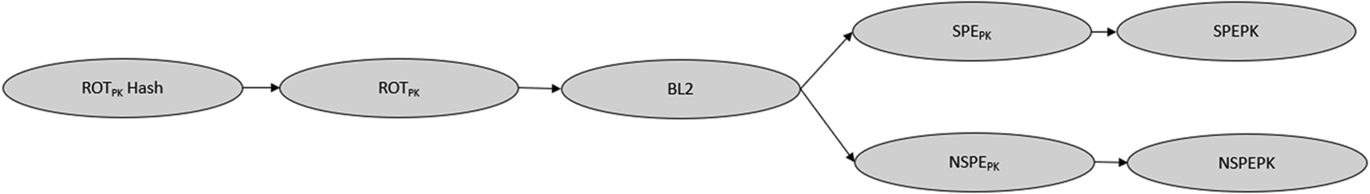
The tier of execution environments shown in Fig. 9.1 will execute a boot flow that establishes the Secure and Non-Secure Processing Environments. In practice, the processor will execute the different images as shown in Fig. 9.3. The immutable RoT is ideally established through a Secure Boot process (BL1) provided by the silicon vendor and preprogrammed into the microcontroller ROM when the device is manufactured. As the code is in the microcontroller ROM, it cannot be modified or updated and is, therefore, “immutable.” When the Secure Bootloader finishes execution, it passes control to the updatable RoT, which is located in the microcontroller FLASH.
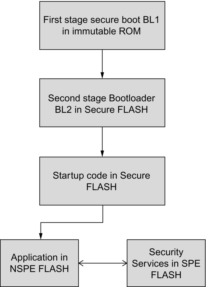
The updatable RoT runs in two phases. The first phase runs as a single thread of execution, and depending on the capabilities of the microcontroller Secure Boot ROM, the updatable RoT may start with a second-stage bootloader (BL2), which is used to validate the SPE and NSPE images. The BL2 bootloader is also capable of managing any firmware updates that are pending. Once the BL2 bootloader has finished, it will pass execution to the SPE code. This is initially a single-threaded code that is used to prepare the device to run the main application. This involves creating the two runtime partitions to host the Non-Secure and Secure Processing Environments. Execution is then passed to the application code, which resides in the NSPE. All the sensitive code and data, such as cryptographic functions and encryption keys, are located in the SPE. As discussed earlier, the SPE will be a separate compute environment that provides a set of trusted secure services to the application code.
Immutable Root of Trust (RoT)
The Immutable RoT is the anchor for the identity and integrity of the device. It is implemented as the microcontroller Secure Boot ROM and will validate the updatable RoT to ensure that only authorized software can run on the device. This requires a RoT key pair to be generated. The private key is used to sign images while the RoT public key will be anchored in the device and used to validate images during boot. At the end of the Secure Boot process, the Immutable RoT will pass a Secure Boot record to the updatable RoT. If present, the second-stage bootloader will extend this boot record with software measurements of all the remaining execution images. The data in the boot record will be used to create an initial attestation record that allows a device to prove its identity to a validating server. The attestation record consists of a unique ID and software component measurements (image hash, version information) that are gathered by the immutable and updatable RoT. These values are formatted using the CBOR encoding rules to make an Entity Attestation Token. We will look at this further in Chapter 13.
Execution environment validation
The Secure Boot process will validate at least one execution environment, normally the second-stage bootloader BL2. The contents of this record are shown in Table 9.2.
| State | Description |
|---|---|
| Version | The PSA Certified firmware version number |
| Signer identity | A signature generated by the device |
| Measurements | Execution image firmware version, size, and signatures |
The PSA security model allows the device images to be validated as either one single image or a series of individual images, which are independently validated.
Single signer
The immutable RoT may be configured to validate all of the execution environments in the updatable RoT. In practice, this means that all of the code in the microcontroller FLASH will be signed by the RoT private key as one single image, as shown in Fig. 9.4.
Multisigner
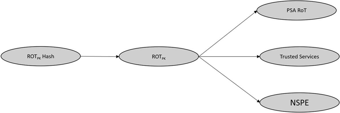
A more sophisticated approach is to create a “chain of trust” linked to the immutable RoT. In this scheme, the immutable RoT validates the first stage of the updatable RoT, which is typically the BL2 bootloader. The updatable RoT will then, in turn, validate each of the remaining execution environments with additional public key pairs, which are part of the second-stage bootloader BL2 (Fig. 9.5).
This approach has two main advantages. First, it allows the secure and nonsecure partitions to be updated independently. Second, it allows different entities to sign the images or components that they provide.
Boot seed
The boot seed is a random 32-bit number that is regenerated on each boot and is used as a session ID. It is included as part of an initial attestation token to ensure that the token is not being reused from a previous session. Previous values of the boot seed are not recorded within our device, but it is assumed that the size of the number is enough to prevent it from accidental reuse.
Updatable Root of Trust (RoT)
The updatable RoT is subdivided into two execution stages. The first is a FLASH-based boot stage which begins execution once the microcontroller Secure Boot ROM has finished. This is a single-threaded code that is located in the microcontroller FLASH and is linked to start execution from the reset vector. The first code to execute will be a second-stage bootloader (BL2), which will update the NSPE and SPE if any new images are available. The BL2 bootloader is also used to validate the existing execution environments, as discussed earlier. Once the BL2 bootloader has finished execution, the Secure and Non-Secure Processing Environments will be configured by the single-threaded secure startup code. Then execution will be passed to the nonsecure application code within the NSPE.
Runtime partitions
Non-Secure Processing Environment
Once the device has booted and the system partitions have been configured, the application code will execute in the Non-Secure Processing Environment. This code can largely be developed as a standard application. Any lessons learned from a threat modeling exercise should feed into the design of this code along with a strict application of secure coding practices. The Non-Secure code can access secure services in the Secure Processing Environment through a local client, which provides a standardized API (Fig. 9.6).

Secure Processing Environment
All sensitive functions and data are located in the Secure Processing Environment in order to be isolated from the general application code. As discussed earlier, the SPE is used to provide security services to code in the NSPE. We could locate security libraries into the Secure Processing Environment and allow the Non-Secure code to make calls directly to the secure functions. However, this would create a large number of calls across the isolation boundary. Each of these would have to be policed for vulnerabilities that could be exploited by an attacker. This is akin to building the wall of a fortress, then creating dozens of gates and then having to defend each and every one.
We need a more sophisticated approach to accessing functions in the Secure Processing Environment. The PSA security model defines two regions within the SPE. These are called the PSA RoT and the Application RoT (Fig. 9.7). Here, code in the Partition Manager and PSA RoT are executing at the CPU privileged level, while code in the application RoT will execute at the unprivileged level.

Both the PSA and Application RoT are further divided into execution partitions. These are somewhat similar to an RTOS thread in that they have their own code and RAM to create a dedicated execution subpartition within the SPE. Each execution subpartition is used to host a security service. The PSA RoT is used to host the mandatory security services while the Application RoT is used to host a protected storage service that is intended to provide general storage for application data. It is also possible to create additional user-defined custom services that are placed in the Application RoT.
Secure partition structure
In order to minimize the number of entry points into the SPE, the security service functions are not called directly from the NSPE. All calls to the different security services are routed through a Secure Partition Manager. This provides a single point of entry to the SPE. The Non-Secure code will make an API call that looks like a standard function call. The API call will actually invoke a Partition Manager Client located in the Non-Secure partition (Fig. 9.8).

The client generates a message to the Secure Partition Manager requesting a security service, and the Secure Partition Manager will, in turn, route this request to the relevant security service to be processed. Any resulting reply will be returned directly to the calling API function in the NSPE. The PSA security model also defines three levels of isolation for the SPE, as shown in Fig. 9.9.
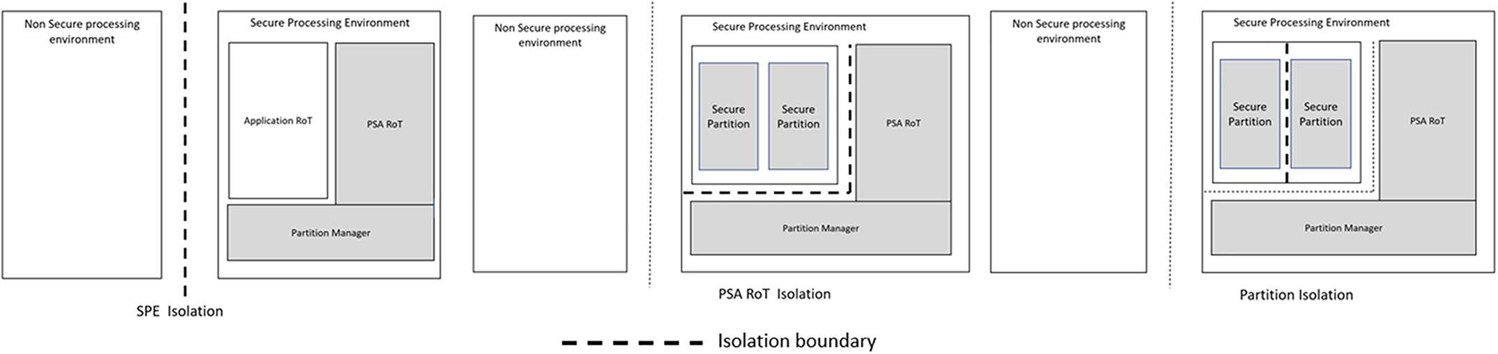
Level 1 isolation
The minimum level of isolation required is to separate the Non-Secure Processing Environment code from the Secure Processing Environment.
Level 2 isolation
The next level creates an additional isolation barrier between the Application RoT and PSA RoT.
Level 3 isolation
To achieve the highest level of isolation each partition within both the Application and PSA RoT must be isolated from each other.
In practice, the TrustZone security peripheral is used to create the Secure and Non-Secure execution environments for level one isolation. The Cortex-M33 Memory Protection Unit is used to create additional isolation barriers within the secure environment.
This approach may look like complicated overkill and would require a lot of additional work to implement from scratch before you even get started on the application code. However, as we will see in the following chapters that much of the isolation requirements can be provided by the Armv8-M TrustZone security peripheral and the Memory Protection Unit. The secure partition and security services are provided as an open-source reference platform called Trusted Firmware for Cortex-M. The TF-M software is also ported to specific microcontrollers as a ready-to-go platform, so you should not need to write any of the Secure Processing Environment code from scratch. Just know how to configure and use it correctly.
Secure Partition Manager (SPM)
The main task of the Secure Partition Manager is to provide an interprocess calling service between client functions and the partition security services. The client functions may be in the Non-Secure code or in other secure partitions within the SPE. For example, a Non-Secure function could request secure storage of a data item. The partition manager will receive this request and pass the command to the secure storage service. In turn, the secure storage service will request encryption and MAC functions from the cryptography service. In addition, the SPM is designed to manage interrupts from peripherals that have been routed to the SPE.
Secure services
PSA RoT services
The updatable Root of Trust provides a set of mandatory security services which are located in the PSA RoT and the Application RoT within the secure partition (Fig. 9.10).
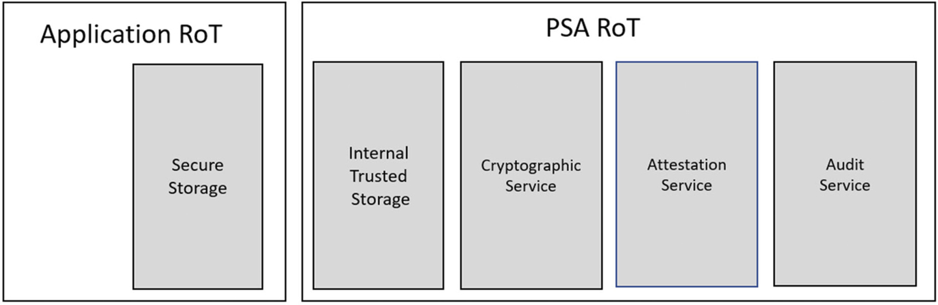
Each service will be introduced here, and then we will set them up and look at them in more detail in Chapter 13.
Secure storage service
The updatable RoT must provide a storage service to manage access to any sensitive data stored within the device, such as cryptographic keys, manufacturer, and user-generated secrets and user-generated private data. To protect this data, the storage service must provide integrity and privacy protection so unauthorized access cannot read or modify the stored data. Protection is further enforced by binding access control policies that ensure that only an owning service can access data stored and bound to that service. The storage service must also provide replay protection so that previously stored data or data acquired from another device cannot be reused on our device.
The secure storage service provides two types of storage volume: Internal Trusted Storage (ITS) and Protected Storage (PS) volumes.
The Internal Trusted Storage is generally a small storage volume that is designed to hold the most sensitive data, such as cryptographic keys. It is intended to be a simple block storage volume that makes use of isolated or shielded memory locations that are within the Secure Partition and are only accessible by the PSA RoT. In a standard microcontroller, this will typically mean that that the ITS is located in internal FLASH memory, which has been allocated to the Secure Processing Environment.
The Protected Storage provides a general storage volume for confidential application data. The Protected Storage Service, which is the service code, is located in the Application RoT, which isolates it from the ITS service. The actual PS volume can be located in either the Secure or Non-Secure partitions depending on your design requirement. It may be implemented as a simple block storage or a full file system.
Like the Internal Trusted Storage, the Protected Storage volume provides integrity, confidentiality, and antirollback. While integrity is always enabled, confidentiality and antirollback are optional and may be enabled or disabled on an item by item basis.
During operation, both the ITS and PS will make calls to the cryptographic service, and each service will have its own keys, which are bound to their respective security service. This concept of binding restricts the key usage to the given service. This associates stored data with a particular device instance, security partition, and lifecycle state.
Cryptographic service
In the earlier chapters covering the TLS cryptographic algorithms, we used the standard mbedTLS library. This library is a general-purpose library and can be used with any Cortex-M microcontroller. As we saw, it is designed to be accessed as a standard C library and makes no special allowance for securely storing cryptographic keys. The Arm Trusted Firmware provides a version of mbedTLS called mbedCrypto that is designed to execute as a cryptographic service within a PSA RoT partition. In addition to the cryptographic algorithms provided by mbedTLS, the mbedCrypto service provides extensive support for key management and storage.
Attestation service
The PSA RoT must also provide an Attestation Service. This service is used to generate tokens that provide proof of identity and integrity to an external attestation server. The attestation token presents the device measurements recorded during the boot process as a set of claims, which are signed by a device Initial Attestation Key (IAK). The device claims include the Implementation ID and information about the recorded boot state of each software component in the device, the current device lifecycle state, the boot seed, and an additional value called the instance ID.
The Initial Attestation Key is provisioned within the device immutable RoT during manufacture. It is the private key of an asymmetric key pair that must be unique to each device. The public half of the key is held in the attestation server, which is used to validate the attestation token and contains an unencrypted Instance ID. This is a public value that allows the attestation server to reconcile the token to the correct attestation public key. The instance ID is calculated as a hash of the public key value, and this can be stored in the device or calculated on the fly.
The device measurements include version numbers and signatures for each executable component, along with the device hardware revision. The boot seed is included each time an Initial Attestation Token is generated. This ensures that each token is unique and prevents impersonation and replay attacks.
Audit
The security services also provide an Audit service, which allows the secure partition to log messages and alerts. The audit messages may only be created by the security services. The audit log may be read and deleted by code in the nonsecure partition.
Application RoT services
By default, the Application RoT contains the Protected Storage service. It is possible to add additional custom services to the Secure Processing Environment. These will be placed in their own partition located in the Application RoT.
Trusted subsystem
In addition to custom services within the Application RoT, the PSA security model also has the concept of a “trusted subsystem.” This could be a Secure Element or a Trusted Platform Module, which provides its own set of security services. Such a subsystem would need to be located within the boundary of the SPE but would have its own RoT that is created in a similar fashion to our main microcontroller RoT.
Secure Boot
As we have seen in the PSA security model, the initial microcontroller must provide a Secure Boot process that creates an immutable Root of Trust. Its key purpose is to validate the initial application boot code, which is the updatable Root of Trust and then hand it over to this code which will validate and boot the main application code.
If you are using a plain old microcontroller that does not provide a Secure Boot mechanism, you will need to provide a first-stage bootloader to perform this functionality. This bootloader must then be stored in the boot FLASH sector, which in turn must be locked from erase and write operations. Fortunately, an increasing number of Cortex-M33-based microcontrollers have been designed with PSA Certified Secure Boot ROM code. All compliant microcontrollers are listed on the PSA certification website. When you are selecting a device, this is the place to start!
PSA parameters
The PSA security model defines a set of stored parameters, which are summarized in Table 9.3.
| Parameter | Parameter | Initial parameter | PSA RoT parameters | Security class | Recommended provisioning |
|---|---|---|---|---|---|
| Implementation ID | Impl_ID | Yes | Yes | Public | Isolated location |
| Hardware Unique Key | HUK | Yes | No | Secret | Shielded/isolated location |
| Boot Validation Key | BVK | Yes | No | Public | Isolated location or Boot ROM |
| Boot Decryption Key | BDK | Yes | No | Secret | Derived from or stored in shielded/isolated location |
| Initial Attestation Key | IAK | Yes | Yes | Secret | Derived from or stored in shielded/isolated location |
| Instance ID | Ins_ID | Yes | Yes | Public | Isolated location |
Lifecycle
Alongside the PSA RoT security services, the security model defines a device lifecycle. The device lifecycle is not a defined service but a set of states that the device may enter during its lifetime. A flow chart of the lifecycle states is shown in Fig. 9.11.

During the initial manufacture, the device will not be locked down in order to allow assembly and test. Once this phase is completed, the PSA RoT must be made fully operational before the device is shipped. This includes programming the SPE and NSPE firmware and provisioning of the PSA RoT parameters and secrets. In this state, the device debug port must also be locked down, and Secure Boot must be enabled.
Once the PSA RoT has been fully provisioned, it may be shipped into the retail chain, ready to be on-boarded into a customer system. At this point, the application code may require further secrets such as user and network credentials. Any application provisioning may only take place once the PSA RoT is operational and must use the PSA RoT services such as the Protected Storage. It is also important that the Application lifecycle is not placed in a state which conflicts with the PSA RoT lifecycle state, i.e., the application is active before the RoT has been fully provisioned.
Once fully provisioned and on boarded to a network the device will be in its operational secure state.
A device must also support debug and repair states. The security model specifies a range of lifecycle debug states as shown in Table 9.4.
| Debug state | Security implications | Information |
|---|---|---|
| Nonrevealing diagnostics | Does not reveal any sensitive user data and secrets, application level secrets, or PSA RoT level secrets. Does not affect the trustworthy operation of any aspect of the device software. | Standard logging, basic diagnostics, and similar device management functions. |
| NS debug | Intrusive debug which compromises NS-level operation, including access to NS-level data and secrets. ARoT, PSA RoT, and boot remain intact and trustworthy. This level of debug must be attested. | Active debugging of nonsecure application software, which does not cross the ARoT isolation boundary. |
| ARoT debug | Intrusive debug which compromises ARoT operation, including access to ARoT level data and secrets. PSA RoT and boot remain intact and trustworthy. | Active debugging which crosses the ARoT isolation boundary, but does not cross the PSA RoT isolation boundary. |
| PSA RoT debug | Intrusive debug which compromises PSA RoT operation, or compromises Secure Boot. | Active debugging which crosses the PSA RoT isolation boundary. With this level of debug enabled the device is no longer attestable. |
Mandatory debug states for the PSA Certified lifecycle.
The different debug states support a range of scenarios, such as nonrevealing logged messages that can be used by a service technician or a nonsecure debug state that allows an authorized technician to connect a debug adapter and view the state of the Non-Secure Application Code. In the case of a serious bug, it is necessary to fully enable the debug port to gain a view of the ARoT and PSA RoT. However, in this case, the device secrets will be compromised, and the device cannot be returned to service without being fully recommissioned.
Most (if not all) Armv7-M-based microcontrollers do not have a debug architecture that can support such finely grained access control. Typically, it is only possible to fully disable the debug port, and it can only be re-enabled by fully erasing the FLASH memory. However, as we will see in Chapter 10, the Cortex-M33 allows you to selectively restrict access to secure and nonsecure regions. It is then up to the Silicon Vendor to implement a hardware access scheme. As we will see in Chapter 11, a typical implementation could be a sophisticated certificate-based scheme that can be used to authorize different entities in combination with varying debug access levels.
This feature of the debug port can also be useful during development. The SPE of a device can be fully provisioned, and the debug view can be limited to the NSPE. This would allow third-party developers to write and debug application which accesses the SPE as a black box.
At the end of its life, a device must be placed in a decommissioned state where all of the PSA RoT parameters are put beyond use. Here, the term “beyond use” will generally mean erasing all sensitive information within the device. Some values may be permanently written into the device, such as OTP fuses, and may need extra care to destroy the stored value. Once a device has entered the decommissioned state, you have effectively killed it. An end-user or service engineer will not be able to return it to a functional state. If the hardware is still fully functional, it may be reclaimed by placing it back into the manufacturing process so that it can be reprogrammed with a fresh set of PSA RoT parameters and then be treated as a new device.
Device requirements
While we can implement the PSA on any Cortex-M-based microcontroller, having a device that provides supporting security features will make your life a lot easier. The features listed below should be considered when selecting a microcontroller.
Isolation architectures
Interrupt routing
Once the MCU's memory has been divided into Secure and Non-Secure Processing Environments, we must also route interrupt vectors to either partition. This allows us to place a peripheral into either partition. For example, we could connect an external interrupt line to an antitamper switch. We would then need to place its interrupt service routine within the secure partition to log any tamper events and take any necessary remedial action.
Secure Boot
The device should have a PSA Certified Secure Boot process. Unless you want to write this yourself this is really a must have.
Unique ID
Each microcontroller should have a unique ID, preprogrammed during its manufacture and accessible through internal registers.
Entropy
The device will contain a True Random Number Generator, which provides a source of high entropy data. This is another must have.
System clocks
The clock tree and other major system peripherals must be located in the Secure Processing Environment and only accessed by secure code.
Oscillator monitoring
The main system clock may be derived from an internal RC oscillator or an external crystal oscillator. Ideally, an internal oscillator should be used as this clock source is hard for an attacker to manipulate. If an external oscillator is used, the microcontroller should provide some form of clock monitoring hardware. In this case, the microcontroller should fall back to an internal oscillator and generate an interrupt or alarm if the external oscillator is halted.
Reset and power
The isolation architecture must be able to locate the registers for software reset and power control within the Secure Processing Environment.
Timers
The Trusted Firmware requires a hardware watchdog, hardware timer, and a real-time clock. Most microcontrollers have one or more hardware watchdog timers. Like the system clocks, the watchdogs must be enabled and maintained by functions running in the SPE. In addition to the watchdog timer, the Trusted Firmware requires a hardware timer and a real-time clock to be located within the SPE.
Monotonic counters
The microcontroller will provide a set of monotonic counters, which can be used for software versioning and antireplay protection.
Real time clock (RTC)
The RTC is used to maintain a calendar date and time for audit logging and to maintain an antirollback scheme for firmware updates. Like the main system clock, we need to ensure that an attacker has not reset, slowed down, or otherwise interfered with the RTC.
Debug
When a device is deployed, the coresight debug port is an obvious target for an attacker. As a minimum, the microcontroller must provide a means to fully disable unauthorized access by a debug agent. To effectively implement the PSA security model, it is desirable to have more configurable access to the debug port that permits different levels of access to the device depending on the user's credentials. For example, an end-user will not be permitted to connect to use the debug port. An authorized service technician may be allowed to connect but only view the nonsecure code, while the design team will be allowed to connect to the device with full debug access.
Shielded memory
It must be possible to place nonvolatile memory such as FLASH, on-chip EEPROM, and OTP fuses into the Secure Processing Environment. A Cortex-M33-based microcontroller may also provide a special section of FLASH memory that is intended to hold RoT data such as certificate and key hashes. Once this region is provisioned, it will be possible to permanently lock it against further updates. In an ideal system, there will also be a revocation system so that compromised secrets can be disabled. We will see a real-world example of this approach in Chapter 11.
Cryptographic accelerators
Ideally, the microcontroller will provide a hardware accelerator for commonly used cryptographic algorithms. Historically, cryptographic accelerators have been developed for symmetrical cryptographic algorithms. However, it is now becoming more common to find accelerators for asymmetrical algorithms.
Assistive architecture
Ideally, the microcontroller will provide additional security assistive hardware such as a key store. We will examine the support provided by a range of microcontrollers in Chapter 11.
Conclusion
In this chapter, we have examined the PSA security model and become familiar with its key requirements. However, these are deliberately abstract so that they can be applied to any type of IoT device. While it is possible to implement the full security model on an ARMv7-M-based microcontroller, you will be faced with a lot of extra work to make it a suitable platform. Such a “plain old microcontroller” has not been designed for the task and lacks many supporting hardware features that you will need to implement in software. Consequently, in the remainder of this book, we will examine how the PSA security model can be implemented on a Cortex-M33 processor using TrustZone and the additional “assistive security features” provided by a microcontroller which has been designed to form the basis of an secure IoT device.