B Answers
Chapter 1 Answers
Chapter 1 Test
1, 2, 3. See local ordinances
4. (a) True (Article 90)
(b) True (Article 90)
5, 6, 7. Contact local agency
Chapter 2 Answers
2–1 Quiz (Closed-Book)
1. Refer to Figure 2-1
2. Contact utility company
3. Service; branch circuits
2–2 Quiz (Closed-Book)
1. Refer to Table 2–2
2. 100 amperes (230.79(C))
3, 4, 5. See text
6. Refer to Figure 2-3
7. Refer to Table 2–1
8. No. 6 (250.66)
9. 100 amperes (230.79)
10. Refer to Code Article 100
2–2 Quiz (Open-Book)
1. Load (amperes)=![]()
No. 3/0 THW (Table 310.16)
2-inch conduit (Table C8)
2. Load = 192 amperes as before
No. 2/0 THHN (Table 310.16)
1½-inch conduit (Table C8)
3. (a) Load (amperes) = ![]() = 41.7 A
= 41.7 A
Requires 60-ampere service (230.79)
No. 6 THW (Table 310.16)
¾-inch conduit (Table C8)
(b) Load (amperes) = ![]() = 83.3A
= 83.3A
No. 4 THW (Table 310.16)
1-inch conduit (Table C8)
(c) Load (amperes) = 83.3 amperes
Requires 100-ampere service (230.42)
No. 3 THW (Table 310.16)
1-inch conduit (Table C8)
See 310.15(B)(6)
(d) Load (amperes) = ![]() =416.7A
=416.7A
3-inch conduit (Table C8)
4. The ampacity is 175 amperes (Table 310.16)
Load = 175 A × 240 V = 42 000 VA
5. (a) 800 amperes (240.4, 240.6)
(b) 150 amperes (240.4, 240.6)
6. (a) No. 8 jumper (250.28)
(b) No. 8 grounding conductor (Table 250.66)
(c) No. 8 bonding jumper (250.104)
7. Load (amperes) = ![]() = 48.1A
= 48.1A
No. 8 THW (Table 310.16)
2–3 Quiz (Closed-Book)
1. 40 amperes (215.2)
2. No. 8 (215.2)
3. No. 8 (275.6)
4. Refer to Code Article 100
5. See text
6. Demand load = .5 × 100 kW = 50 kW
2–3 Quiz (Open-Book)
1. (a) Line load = ![]() = 125 A
= 125 A
(b) No. 1 THW (Table 310.16)
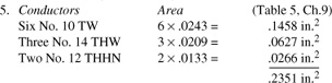
(c) Area = 3 × .1901 in.2 = .5703 in.2 (Table 5, Ch. 9)
(d) 1¼-inch conduit (Table C8)
2. (a) Line load = ![]() = 36 A
= 36 A
(b) No. 8 THW (Table 310.16)
(c) Area = 4 ×. 0556 in.2 = .2224 in.2 (Table 5, Ch. 9)
(d) ¾-inch conduit (Table C8)
3. (a) Line load = ![]() = 417A
= 417A
(b) Neutral ampacity = 200 A + .7 (417 - 200A)
= 351.9 A (220.61)
(c) Ungrounded conductors: 600 kcmil (Table 310.16)
Neutral: 500 kcmil (Table 310.16)
4. Neutral ampacity = 200 A + .7 (1000 A - 200 A) = 760 A (220.61)
2–4 Quiz (Closed-Book)
1. Refer to Code Article 100
2. No. 14 [210.19(A)]
3. 15, 20, 30, 40, and 50 amperes (210.3)
4. Yes, as an individual branch circuit (210.3)
5. Load (amperes) = ![]() = 41.7A
= 41.7A
A 50-ampere circuit would be used
2–4 Quiz (Open-Book)
1. Load (amperes) = ![]() = 83.3A
= 83.3A
Use: (1) No. 4 Type THW copper conductors for individual branch circuit (Table 310.16)
(2) Standard 90-ampere overcurrent device (240.6)
(3) No. 8 copper equipment grounding conductor (Table 250.122)
(4) 1-inch conduit to enclose three No. 4 and one No. 8 THW conductors (Table C8)
2. Load (ampears) = ![]() = 24A
= 24A
Use: (1) No. 10 Type THW conductors (Table 310.16)
(2) 25- or 30-ampere overcurrent protective device (240.6)
(3) No. 10 THW equipment grounding conductor (250.122)
(4) ¾-inch conduit to enclose five No. 10 Type THW conductors (Table C8)
Chapter 2 Test
I. (True or False)
1. F (Article 100)
2. F (230.42, 230.79)
3. T (230.42, 250.24)
4. T [230.79(A)]
5. F (Article 100)
6. T (Table 1, Ch. 9)
7. F (230.79)
8. F (210.21)
9. T (210.3)
10. F (230.42)
II. (Multiple Choice)
1. (d) (230.42)
2. (c) (220.61)
3. (b) ![]() × 2400 V = 4160 V
× 2400 V = 4160 V
4. (b) (250.102)
5. (b) (220.61)
6. (d) (Article 100)
7. (b)
8. (b) (210.3)
9. (a) (220.18)
III. (Problems)
1. Load (amperes) = ![]() = 383A
= 383A
(a) 500-kcmil type THHN (Table 310.16)
(b) Neutral current = 200 A + .7 × 183 A
(b) Neutral current = 328 A
Use 350-kcmil THHN for neutral
(c) 400-amperes standard (240.4, 240.6)
(d) No. 1/0 (Table 250.66)
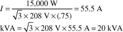
2. Load (amperes) = ![]() = 55.5A
= 55.5A
Use four No. 4 Type THW aluminum (Table 310.16)
Use 1¼-inch conduit (Table C8)
3. (a) Load (amperes) = ![]() = 416.7A
= 416.7A
(b) Load (amperes) = ![]() = 277.5A,
= 277.5A,
300-Kcmil THW
(c) Load (amperes) = ![]() = 120.3A,
= 120.3A,
No. 1 THW
(d) Same as (c)—three conductors only
4. (a) Feeder demand = 20 kW ×. 5 = 10 kW
Load (amperes) = ![]() = 41.7A
= 41.7A
(b) Service demand = .35 (20 kVA + 20 kVA) = 14 kVA
Load (amperes) = ![]() = 58.3A
= 58.3A
(c) Use No. 8 THW conductors for feeders and No. 6 THW for service (Table 310.16)
Since 40% area must be greater than .2351 in.2, use 1-inch conduit (Table 4, Ch. 9)
Chapter 3 Answers
3–1.1 Quiz (Closed-Book)
1. (a) (220.14)
2. True [210.19(A)]
3. True [210.23(A)]
4. 10 ft × 180 VA/5 ft = 360 VA [220.14(H)]
5. 200 W/ft × 20 ft = 4000 W [220.14(G)]
6. Lighting is continuous (Article 100)
7. Only fixed units [210.23(B)]
3–1.1 Quiz (Open-Book)
1. Load = 200 VA/ft × 30 ft × 1.25 = 7500 VA [220.14(G)]
![]() = 4.2, or 5 circuits
= 4.2, or 5 circuits
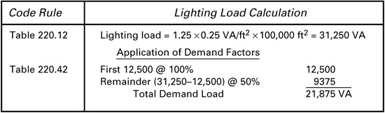
2. Load = 1.25 × 3.5 VA/ft2 × 5000 ft2 = 21 875 VA
[220.12]
3. ![]() = 9.1, or 10 circuits
= 9.1, or 10 circuits
4. Lighting:
![]() = 5.2, or 6 circuits
= 5.2, or 6 circuits
Show windows:
![]() × 1.25 = 1.04, or 2 circuits
× 1.25 = 1.04, or 2 circuits
Receptacles:
![]() = 9.37, or 10 circuits
= 9.37, or 10 circuits
Fluorescent lights:
![]() = 2.78, or 3 circuits
= 2.78, or 3 circuits
Total eighteen 20-ampere circuits, three 30-ampere circuits
3–1.2 Quiz (Closed-Book)
1. See Article 100
2. See Figure 3–4
3. (c) (430.6)
4. (a) (430.32)
5. A motor-circuit switch or a circuit breaker (430.109)
6. F (430.83)
7. F [430.32(B)(4)]
3–1.2 Quiz (Open-Book)
1. FLA = 54 A (Table 430.250)
Ampacity = 1.25 × 54 A = 67.5 A minimum (430.22)
Relay set at 1.15 × 54 A = 62.1 A maximum [430.32(A)]
2. 1.25 × 54 A = 67.5 A [430.32(A)]
3. FLA = 9.6 A (Table 430.250)
Ampacity = 1.25 × 9.6 A = 12 A (430.22)
No. 14 THW conductors (Table 310.16)
4. FLA = 34 A (Table 430.250)
Ampacity = 1.25 × 34 A = 42.5 A (430.22)
Overload = 1.25 × 34 A = 42.5 A (430.32)
Branch-circuit protection = 1.5 × 34 A = 51 A (Table 430.150)
(The motor is a wound-rotor motor)
Controller and disconnecting means ratings: 25 horsepower
Use conduit as the equipment grounding conductor or No. 8 aluminum (Table 250.122)
Thus, three No. 6 THW aluminum conductors (Table 310.16) and a ¾-inch conduit (Table C8) are required.
5. FLA = 50 A (Table 430.248)
Ampacity: 1.25 × 50 A = 62.5 A (430.22)
Overload: 1.15 × 50 A = 57.5 A (430.32)
Branch-circuit protection: 2.5 × 50 A = 125 A (Table 430.52, Code letter B motor)
Controller and disconnecting means ratings: 10 horsepower
Equipment grounding conductor: No. 6 copper (Table 250.122)
Thus, two No. 4 TW copper conductors (Table 310.16) and a 1-inch conduit with equipment ground (Table 3A, Ch. 9) are required.
3–1.3 Quiz (Closed-Book)
1. See Article 100, Definitions
2. A water heater of 120 gallons or less capacity (422.13)
3. F (Table 220.55, Note 4)
4. (b) (Table 220.55, Note 1)
5. F [220.14]
6. 1.25 × 10 A + 20 A = 32.5 A [220.18]
1. (a) 8 kilowatts (Table 220.55, column C)
(b) 8 kilowatts (Table 220.55, column C)
(c) 8 kW + (2 × 400 W) = 8800 W (Table 220.55, Note 1)
(d) 5 kW × .8 = 4 kW (Table 220.55, column B)
2. FLA = 8 A (Table 430.248)
Ampacity = 1.25 × 8 A = 10 A; use 15-ampere circuit
Disconnecting means: ac snap switch (430.109) or circuit breaker
3. Load (amperes) = ![]() = 25 A
= 25 A
No. 10 THW aluminum conductors (Table 310.16)
or use a 30-ampere circuit with No. 8 conductors (240.4).
4. Load = 9 kW + 8 kW = 17 kW (Table 220.55, Note 4)
Demand = 8 kW + 400 W (17 – 12) = 10 kW
Load (amperes) = ![]() = 4.17 A;
= 4.17 A;
use No. 8 type THW copper conductors (Table 310.16)
5. Load (amperes) = ![]() = 12.0 A
= 12.0 A
Overcurrent protection: 15 A
No. 14 MI conductors [Table 310.16, 210.19(A)]
3–1.4 Quiz (Closed-Book)
1. 20 A × 1.25 = 25 A [424.3(B)]
2. 15, 20, 25, or 30 amperes [424.3(A)]
3. (a) [424.3(B)]
3–1.4 Quiz (Open-Book)
1. Load (amperes) = 1.25 × ![]() = 52 minimum
= 52 minimum
[424.3(B)]
2. FLA = 17 A (Table 430.248)
Heater current = ![]() = 20.8 A
= 20.8 A
Load (amperes) = 1.25 × (17 A + 20.8 A) = 47.3 A [424.3(B)]
No. 8 THW copper conductors (Table 310.16)
Overcurrent protection: 50 A standard (240.6)
Equipment grounding conductor: No. 10 (Table 250.122)
3. Load (amperes) = 1.25 × ![]() = 25 A (424.3)
= 25 A (424.3)
This requires two 15- or 20-ampere circuits or one 30-ampere circuit. [424.3(A)]
3–1.5 Quiz (Closed-Book)
1. (a) 1.25 × 100 A = 125 A (440.32)
(b) 1.75 × 100 A = 175 A [440.22(A)]
(c) 1.15 × 100 A = 115 A [440.12(A)(1)]
(d) 1.25 × 100 A = 125 A [440.52(A)(3)]
2. (b) [440.41(A)]
3. 1.25 × 12 A = 15 A [440.62(B)]
4. 15 A/2 = 7.5 A [440.62(C)]
5. Six times rated-load current [440.12(C)]
6. Ampere rating and horsepower rating [440.12(A)]
3–1.5 Quiz (Open-Book)
1. Ampacity = 1.25 × 20 A = 25 A (440.32)
Overload protection: 1.4 × 20 A = 28 A maximum [440.52(A)]
Branch-circuit protection: 1.75 × 20 A = 35 A maximum (440.22)
Disconnecting means: 1.15 × 20 A = 23 A minimum (440.12)
Thus, No. 10 THW copper conductors (Table 310.16); 35 A circuit breaker for overcurrent protection and disconnecting means; overload relay set at 28 amperes.
2. Current rating = 14 A (Table 430.250)
Equivalent locked-rotor rating = 81 A (Table 430.251)
The 10-horsepower controller may control a motor-compressor with the above ratings [440.41(A)]
3. (a) Disconnecting means
Current rating: 1.15 × 124 A = 142.6 A [440.12(A)(1)]
Locked rotor equivalent: 100 horsepower (based on 730 amperes) (Table 430.251)
Full-load equivalent: 100 horsepower (based on 124 amperes) (Table 430.250)
Thus, required horsepower rating is 100 horsepower [440.12(A)(2)]
(b) Controller
Current rating: 124 amperes (full-load current) [440.41(A)] and 730 amperes (locked-rotor current)
4. Based on 750-ampere locked-rotor current, the equivalent horsepower rating is 125 horsepower (Table 430.251) [440.12(A)(2)]
3–1.6 Quiz (Closed-Book)
1. 50% of branch-circuit rating [210.23(A)]
2. (a) Appliances and fixed lighting units [210.23(B)]
(b) Appliances
3. Load is 8 amperes
A 20-ampere circuit is required (16 amperes or greater) (440.62)
4. 125% of motor full-load current (430.25) plus the current of the other load
5. (a) [430.110(C)(2)]
3–1.6 Quiz (Open-Book)
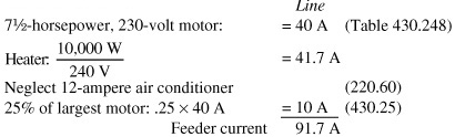
1. Motor: FLA = 50 A (Table 430.248)
Heater: I = ![]() = 4.2 A
= 4.2 A
Total load = 1.25 × 50 A + 4.2 A = 66.7 A (430.25)
Use No. 4 THW copper conductors (Table 310.16)
3–1.7 Quiz (Closed-Book)
1. (b) (430.22)
2. 16 amperes [210.19(A)]
3. Code table [Table 430.248]
4. (c) (Table 430.52)
5. 180 volt-amperes [220.14(I)]
6. 225 volt-amperes [210.19(A), 220.14(I)]
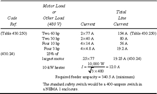
1. (a) 9.8 amperes (Table 430.248)
(b) 4.9 amperes (Table 430.248)
(c) 9.6 amperes (Table 430.250)
(d) 4.8 amperes (Table 430.250)
2. FLA = 14 A (Table 430.250)
Ampacity = 1.25 × 14 A = 17.5 A
3. 800% of FLA (Table 430.52)
8 × 14 A = 112 A
Standard Size is 125 amperes (240.6)
4. Load ![]() A
A
The circuit rating must be 1.25 × 208.3 A = 260.4 A or greater if the overcurrent protective device is not rated for 100% continuous duty.
5. Use 4/0 THW copper conductors (Table 310.16)
6. Number![]() or 11 circuits
or 11 circuits
7. Number![]()
or 13 circuits (220.3) (See Problem 8)
8. Load per unit![]() A/unit
A/unit
Units/circuit![]() or 8 per circuit
or 8 per circuit
thus, 13 circuits must be provided to supply 100 outlets.
9. (a) Lighting load![]() A
A
Use two 20-ampere circuits
(b) Motor full-load current is 34 amperes (Table 430.250)
Conductor ampacity = 1.25 × 34 A = 42.5
Requires three No. 8 THW copper conductors
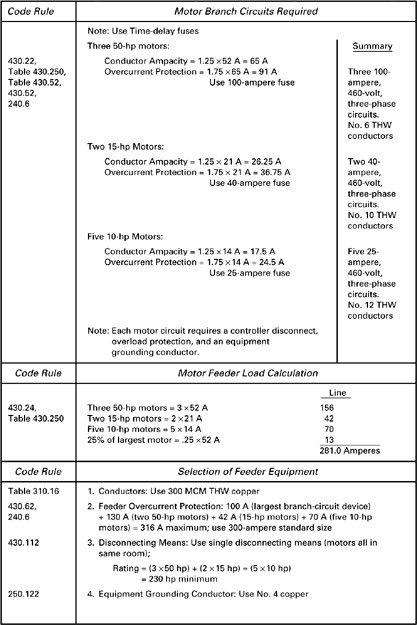
Fuse can be rated as high as 3 × 34 A = 102 A (Table 430.52)
Use standard 110-ampere fuse
A 25-horsepower rated controller is required
(c) The fluorescent lighting load per unit is 1.25 × 1.7 A = 2.1 A [220.4(B)]
Ten such units require a 21-ampere supply. A 30- ampere branch circuit could be used if the lampholders were heavy-duty type [210.21(A)]
(d) (1) Unit load (continuous)![]() A
A
[220.14(E)]
(2) Units per 30-ampere circuit is
![]() or 4 per circuit
or 4 per circuit
Requires three 30-ampere circuits
3–2.1 Quiz (Closed-Book)
1. (b) (220.43)
2. 180 volt-amperes [220.14]
3. Circuits supplying household electric ranges (220.61)
4. (b) (220.61)
5. The current drawn by the load and whether the load is continuous or not (220.40)
3–2.1 Quiz (Open-Book)
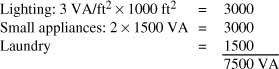
1. Lighting: 10,000 ft2 × 3.5 VA/ft2 × 1.25
Receptacles: 100 × 180VA × 1.25
Connected Load
43 750 VA
22 500 VA
66 250 VA
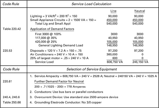
Load in amperes = 66 250/240 V = 276 A
Neutral load: 200 A + .7 (76 A) = 253 A (220.61)
THW copper conductors: Use two 300 kcmil and one 250 kcmil (neutral) (Table 310.16)
2. (a) Incandescent load (amperes)![]() A
A
Neutral load = 200 + (.7 × 233 A) = 363 A (220.61)
(b) Fluorescent load current:![]() A
A
(c) Total neutral: 363 + 217 A = 580 A
(d) Total load: 433 A + 217 A = 650. THW aluminum conductors: The line conductors must be larger than 2000 kcmil or equivalent (Table 310.16)
3. The overcurrent protective device in a panelboard must be set at (43,750 VA + 22,500 VA)/240 V = 276 A or greater because the loads are continuous. A standard 300-A device could be used. Two 300-kcmil THW copper conductors could be used with the 300-A device. (220.40) (240.4)
3–2.2 Quiz (Closed-Book)
1. The feeder overcurrent protective device is selected based on the rating of the largest branch-circuit protective device and the full-load currents of any other motors connected to the feeder. (430.62)
2. The feeder load is the sum of the full-load current of the motors plus the current drawn by any other loads, plus 25% of the full-load current of the motor with the largest full-load current. (430.24)
3–2.2 Quiz (Open-Book)
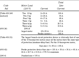
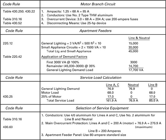
1. FLA = 50 amperes for each 10-horsepower, 230-volt motor (Table 430.248)
Branch-circuit protective device: 8 × 50 A = 400 A maximum (Table 430.52)
Feeder ampacity: 50 A + 50 A + 50 A + (.25 × 50 A) = 162.5 A (430.24)
THW copper conductors: Two No. 2/0 (Table 310.16)
Feeder protective device: 400 A + 50 A + 50 A = 500 A maximum (430.62)
2. Compressor
5-horsepower, 480-volt, three-phase motor
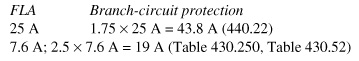
Feeder ampacity: 25 A + 7.6 A + (.25 × 25 A) = 38.9 A (430.24, 440.33)
THW aluminum conductors: Three No. 8 (Table 310.16)
Feeder protective device: 43.8 A + 7.6 A = 51.4 A maximum (430.62, 240.6) Use 50-ampere standard breaker
1. T (220.51)
2. T (220.50)
3. (c) (Table 220.56)
4. Five (Table 220.54)
5. 70% (220.61)
3–2.3 Quiz (Open-Book)
1. 
THW copper conductors: Two No. 3 (Table 310.16)
Since the branch-circuit protective device is not specified, the rating of the feeder protective device cannot be selected.
2. [35-.5(7)]% × 30 × 5 kW = 47.3 kW (Table 220.54)
3. The load for twenty-five 10-kilowatt electric ranges is 40 kilowatts (Table 220.55)
The neutral load is .7 × 40 kW = 28 kW (220.61)
4. 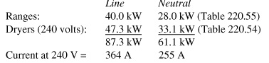
THW copper conductors: Two 500 kcmil, one 250 kcmil (neutral) (Table 310.16). Feeder protective device: 400 A standard (240.6)
3–2.4 Quiz (Closed-Book)
1. (a) 115 V × 16 A = 1840 VA
(b) 230 V × 28 A = 6440 VA
(c)![]() × 460 V × 10 A = 7967 VA
× 460 V × 10 A = 7967 VA
2. If there is no feeder demand factor, the feeder load is equal to the sum of the branch-circuit loads for lighting loads, receptacle loads, and certain nonmotor-driven appliance loads.
3. The motors must meet the conditions of Code rule 430.112.
3–2.4 Quiz (Open-Book)
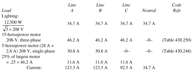
1. 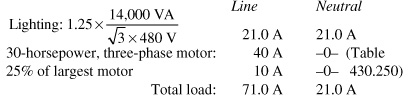
2. 
NOTE: This is not intended to be a feeder for a dwelling as discussed in Chapter 4.
3–2.5 Quiz (Closed-Book)
1. Doubles
2. Four [310.15(B)(2)]
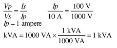
3. kVAin = kVAout
4. Power factor![]()
5. Line-to-line = 240 V
Line-to-neutral = 120 V, 120 V, 208 V
3–2.5 Quiz (Open-Book)
1. 
2. ![]()
3. ![]()
(b) Power per phase![]()
4. ![]()
The ampacity of the conductors must be reduced to 80% since there are four conductors in the conduit. [310.15(B)(2)]. The ampacity of the circuit must be ![]()
Number of 500-kcmil conductors![]() or four per phase in four conduits
or four per phase in four conduits
Chapter 3 Test
I. (True or False)
1. F (210.3)
2. T [210.21(A)]
3. F [210.20(A)]
4. F [210.23(B)]
5. T (Article 100)
6. T (220.61)
7. T (Table 220.55)
8. T (422.30)
9. F [424.3(A)]
10. T [440.22(A)]
II. (Multiple Choice)
1. (b) [210.20(A)]
2. (b) (Table 310.16)
3. (a) (210.3)
4. (b) [220.14]
5. (c) (220.14)
6. (b) (430.22)
7. (b) [430.32(A)]
8. (a) (430.24)
9. (b) [430.62(A)]
10. (c) (310.4)
III. (Problems)
1. Each receptacle is a load of 180 volt-amperes [220.14]. As a noncontinuous load, the current per receptacle at 120 volts is ![]()
The number per circuit is
![]() or 13 receptacles
or 13 receptacles
2. (a) FLA = 5.8 amperes (Table 430.248)
Ampacity: 1.25 × 5.8 A = 7.25 A
No. 14 THW copper conductors (Table 310.16)
Branch-circuit protection: 3 × 5.8 A = 17.4 A maximum (Table 430.52)
Use either a 15-ampere or 20-ampere circuit (No. 12 conductors)
(b) Load![]()
No. 14 THW copper conductors (Table 310.16)
Use a 15-ampere circuit
3. 
THW aluminum conductors: three 350 kcmil; No. 1/0 neutral
4. Load (amperes)![]()
(Assuming the load is not continuous)
Demand load = .65 × 364.8 A = 237.13 A (Table 220.56)
5. (a) Load = 8 kW + 400 W (17 - 12) = 10 kW (Table 220.55 Note 1)
(In this case, an excess of 5 kilowatts over 12 kilowatts was used since the calculated excess was 4.6 kilowatts and was rounded off to 5 kilowatts)
(b) Demand load = 20 kW (Table 220.55)
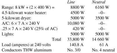
6. 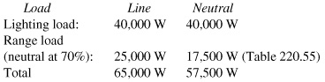
Load (amperes) = 270.8 A
Neutral = 200 A + .7 (39.6 A) = 227.7 A (220.61)
THW conductors: 300 kcmil, No. 4/0 neutral
Main overcurrent: 270.8 amperes, use 300-ampere standard (230.90, 240.6)
Disconnecting means: 270.8 amperes minimum (230.79)
Grounding electrode conductor: No. 2 copper (250.66)
Conduit: 2 × 300-kcmil THW = 2 × .5281 = 1.0562 in2
No. 4/0 ![]()
(Table 5, Ch. 9)
Use ![]() inch conduit (Table 4, Ch. 9)
inch conduit (Table 4, Ch. 9)
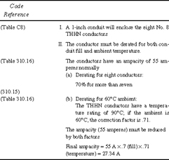
7. Ampacity of No. 3 conductor: 100 amperes (Table 310.16) Ampacity of four No. 3 conductors: 4 × 100 A = 400 A Reduced ampacity for 12 conductors in conduit: .7 × 400 A = 280 A (310.15(B), Annex B)
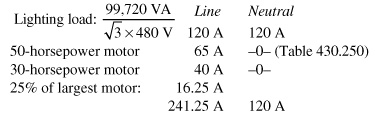
8.
THW Aluminum conductors: No. 2/0, No. 2/0, No. 1, No. 8 (Table 310.16)
(1) 25-horsepower squirrel-cage
FLA = 34 A (Table 430.250)
Ampacity: 1.25 × 34 A = 42.5 (430.22)
No. 8 THW copper conductors (Table 310.16)
Branch-circuit protection: 3 × 34 A = 102 A, or 110- ampere standard fuse (Table 430.52, 240.6)
Overload: 1.15 × 34 A = 39.1 A maximum (430.32)
Controller: 25-horsepower (430.83)
Disconnecting means: 25-horsepower motor-circuit switch (430.110)
Conduit enclosing three No. 8 THW conductors: ¾ inch (Table C8)
(2) 30-horsepower wound rotor:
FLA = 40 A
Ampacity: 1.25 × 40 A = 50 A (Table 430.250)
No. 8 THW copper conductors (Table 310.16)
Branch-circuit protection: 1.5 × 40 A = 60 A fuse (Table 430.52)
Overload: 1.15 × 40 A = 46 A maximum (430.32)
Controller: 30-horsepower (430.83)
Disconnecting means: 30-horsepower motor-circuit switch (430.110)
Conduit enclosing three No. 8 THW conductors: ¾ inch (Table C8)
(b) Feeder:
Ampacity: 1.25 × 40 A + 34 A = 84 A (430.24)
No. 4 THW copper conductors (Table 310.16)
Feeder overcurrent protection: 110 A + 40 A = 150 A maximum (430.62)
Conduit enclosing three No. 4 THW conductors: 1 inch (Table C8)
(The conduit is used as the equipment grounding conductor)
IV. (Special Problems)
1. ![]()
2. (a) Ampacity:
The circuit ampacity is 25 A × .8 = 20 A (Table 310.16, 310.15(B))
(b) Branch-circuit overcurrent device:
The conductors must be protected at 20 amperes or less
3. 
4. 
5. FLA = 15.2 A with unity power factor (Table 430.250)
![]()
Ampacity = 1.25 × 19 A = 23.75 A (430.22)
No. 10 THW copper conductors (Table 310.16)
Chapter 4 Answers
4–1.1 Quiz (Closed-Book)
1. Outside dimensions [220.12]
2. (a) General lighting circuits (210.11)
(b) Small appliance circuits
(c) Laundry circuit
(d) Bathroom circuit
3. 8 kilowatts (Table 220.55, Note 4)
4. 3 watts [Table 220.12]
5. 20 amperes (210.11)
4–1.1 Quiz (Open-Book)
1. Yes, if circuit conductors are rated 50 amperes [422.11(E)]
2. (a) Lighting (use 20-ampere circuits):
![]()
Use two 20-ampere circuits with No. 10 conductors [220.12]
(b) Small appliance, laundry, and bathroom circuits: Use four 20-ampere circuits with No. 10 conductors [210.11(C)]
(c) 12-kilowatt range: Load given as 8 kilowatts (220.55) Load (amperes) = 8000 W ÷ 240 V = 33.3 A; use 40-ampere, 120/240-volt circuit with No. 8 THW aluminum conductors (40 A); required ampacity = .7 × 40 A = 28 A; use No. 10 for neutral conductor (210.19)
3. (a) Lighting area = 
No. of 20-ampere circuits =
![]()
Use three 20-ampere circuits with No. 12 conductors [220.12]
Small appliance, laundry, and bathroom: use four 20-ampere circuits with No. 12 conductors [210.11(C)]
(b) 12-ampere, 230-volt compressor: 1.25 × 12 A = 15 A (440.32)
Use 15- or 20-ampere, 240-volt circuit
(c) 12-kilowatt range; Load given as 8 kilowatts (220.55)
Load (amperes) = 8000 W ÷ 240 V = 33.3 A
Use 40-ampere, 120/240-volt circuit with No. 8 conductors (50 A)
Neutral ampacity = .7 × 40 A = 28 A; use No. 10 conductor
(d) 5-kilowatt, 240-volt space heating:
![]()
Use 30-ampere, 240-volt circuit with No. 10 conductors
1. 4500 watts (220.52)
2. 5000 watts (220.54)
3. (b) (Table 220.42)
4. 100 amperes (230.42)
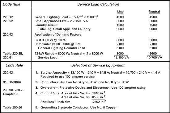
4–1.2 Quiz (Open-Book)
See Detailed Calculations in Appendix B
4–1.3 Quiz (Closed-Book)
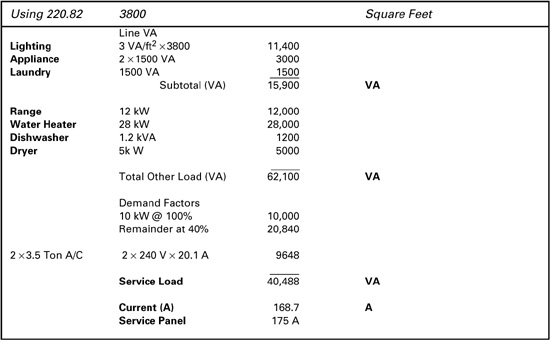
1. Nameplate rating (220.82)
2. True
3. (b)
4. See Code section 220.82
5. 40% of Nameplate rating (220.82)
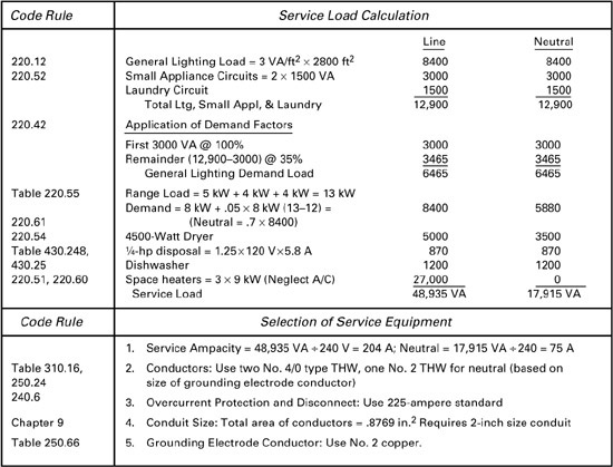
4–1.3 Quiz (Open-Book)
See Detailed Calculations in Appendix B
4–1.4 Quiz (Closed-Book)
1. 60 A × 208 V = 12 480 VA
2. 8000 VA + .4 (X – 8000) VA = 12 480 VA (220.83)
4–1.4 Quiz (Open-Book)
1. (a) Existing loads are
(b) Water heater is subject to 40% demand and may have connected load of 24,000 VA – 19,000 VA = 5000 VA maximum (220.83)
2. Maximum added air-conditioning load (L) is
L + 8000 W + .4 (19,000 – 8000) W = 14,400 W
L = 2000 W (220.83)
4–1.5 Quiz (Closed-Book)
1. The service must be at least 100 amperes. The optional calculation (220.82) usually results in a smaller service than the standard calculation when there is a large heating and appliance load because of the application of demand factors to central heating and other loads
2. (a) Required branch circuits are
(1) ![]()
(2) Two 20-ampere small appliance circuits
(3) One 20-ampere laundry circuit
(4) One 20-ampere bathroom circuit
A total of six 20-ampere circuits are required
(b) Service load is
Application of demand factors
![]()
![]()
Minimum service size is 100 amperes (230.42) (For a three wire service)
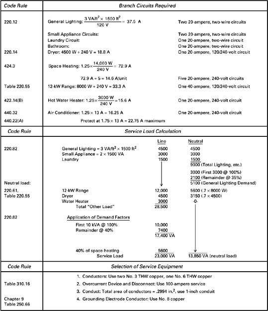
4–1.5 Quiz (Open-Book)
See Detailed Calculations in Appendix B
4–2.1 Quiz (Closed-Book)
1. (b) (220.42)
2. 5000 watts (220.54)
3. Five (220.54)
4–2.1 Quiz (Open-Book)
See Detailed Calculations in Appendix B
4–2.2 Quiz (Closed-Book)
1. Three (Article 100-Definitions) (220.84)
2. False [220.84(B)]
4–2.2 Quiz (Open-Book)
See Detailed Calculations in Appendix B
4–2.4 Quiz (Closed-Book)
1. Connected load is 400 kilovolt-amperes
Demand load is:
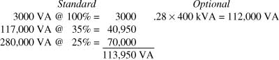
There is no significant difference in demand loads
4–2.4 Quiz (Open-Book)
See Detailed Calculations in Appendix B
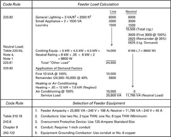
4–3 Quiz (Open-Book)
See Detailed Calculations in Appendix B
Chapter 4 Test
I. (True or False)
1. F [(220.12)]
2. F [(220.55)]
3. F [210.52(F), Exception 1, 2]
4. T [424.3(B)]
5. T (220.40)
6. T (220.54)
7. F (220.82)
8. T [220.84(A)(3)]
1. (c) [422.11(E)]
2. (b) (Table 220.42)
3. (b) (220.82)
4. (c) (220.83)
5. (a) (220.82)
6. (a) (220.82)
7. (c) (250.24)
8. (a) [210.19(A)]
III. (Problems)
See Detailed Calculations in Appendix B
Chapter 5 Answers
5-1 Quiz (Closed-Book)
1. (b) [240.21]
2. Yes; the neutral may not be smaller than the grounding electrode conductor (250.24)
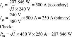
3. Rated primary current is 10,000 kVA / 480 V = 20.8 A The maximum primary feeder overcurrent device setting is 2.5 × 20.8 A = 52 A; maximum size of secondary side overcurrent device is 1.25 × (10,000 kVA / 240 V) = 52 A [450.3(B)]. Maximum standard size is 60 A.
5–1 Quiz (Open-Book)
See Detailed Calculations in Appendix B
5–2 Quiz (Closed-Book)
1. (b) (Table 220.56)
2. (b) (Table 220.88)
3. (c) (Table 220.102)
4. (a), (c) (Table 220.42)
5–2 Quiz (Open-Book)
See Detailed Calculations in Appendix B
5–3 Quiz (Closed-Book)
1. 3 [550.18, 552.46]
2. 16 000 [550.31]
3. 35 [550.18(A), 552.47(A)]
4. (a) (555.12)
5. (b) (645.5)
6. (c) [550.10(A)]
5–3 Quiz (Open-Book)
1. See Detailed Calculations in Appendix B
2. 20 × 16,000 VA × .25 = 8000 VA (550.31)
3. 30 amperes [551.44(C)]
4. 
5. 5 × 30 A × .9 = 135 A (555.12)
Chapter 5 Test
I. (True or False)
1. T [Table 220.14]
2. T (408.34)
3. T (210.4)
4. T [210.6(C)]
5. F (See text)
6. F (215.2)
7. F (555.19)
8. F (220.86)
9. F (550.31)
10. T (Table 220.56)
II. (Multiple Choice)
1. (b) [422.11(E)]
2. (c) 1.25 × 30 × 600 VA = 22 500 VA [220.14]
3. (a) [Table 220.12]
4. (a) (240.4)
5. (b) [460.8(A)]
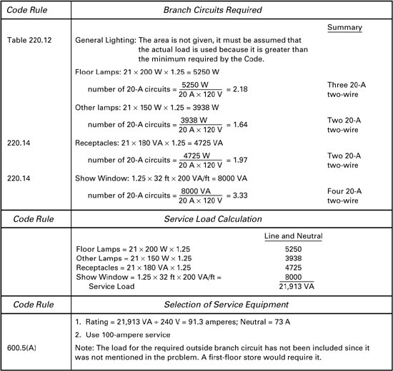
6. (c) [600.5(B)]
7. (a) [450.3(B)]
8. (a) [Table 220.12]
9. (c) (Table 220.103)
10. (c) (Table 220.42)
III. (Problems)
See Detailed Calculations in Appendix B
Chapter 6 Test
I. (True or False)
1. T (210.4, Exception 2)
2. T [210.5(C)]
3. F (210.5, 250.119)
4. T [210.8(A)(1)]
5. F [210.8(A)]
6. F [210.70(A)(1), Exception 1]
7. T [230.24(A)]
8. F [230.24(B)]
10. T [230.71(A)]
11. T (230.75)
12. T (250.142)
13. F (250.53)
14. F (250.56)
II. (Multiple Choice)
1. (b) [210.52(A)]
2. (c) [210.52(A)]
3. (a) (210.52)
4. (b) [210.52(H)]
5. (a) (210.63)
6. (d) [210.8(A)]
7. (d) [210.70(A)]
8. (a) (210.62)
9. (c) [230.24(B)]
10. (a) (250.24)
11. (c) (250.20)
12. (a) (250.28)
III. (Fill in the Blanks)
1. 120 (210.6)
2. 5½ (210.52)
3. 12 [210.52(C)]
4. 12 [230.24(B)]
5. 10 [230.50(B)]
6. Raintight (230.54)
7. 24 [230.54(C)]
8. 8 (250.52)
9. 8 (250.53(G))
10. 2 (250.52)
Chapter 7 Test
I. (True or False)
1. T (240.4)
2. F (240.21)
3. T [310.12(A), 200.6]
4. F (310.15)
5. T (Chapter 9, Tables 8, 9)
6. T (400.8)
7. T (402.6)
8. F [300.4(A)(1)]
9. F (300.14)
10. T (110.14)
11. T (310.4)
12. F [300.19(A)]
13. T [300.5(A)]
14. F [300.5(D)]
15. T (392.4)
16. F (398.15)
17. T (328.2)
18. T (334.104)
19. T (358.12)
20. F (360.12)
21. T (366.56(B)]
22. T (250.97)
23. F [240.51(B)]
24. T [314.16(B)]
25. T (314.29)
26. F [404.14(A)(2)]
27. T (410.8)
II. (Multiple Choice)
1. (b) [200.6(B)]
2. (d) (240.6)
3. (a) [240.50(A)]
4. (b) (240.60)
5. (c) (250.110, Exception)
6. (a) (250.140)
7. (b) (250.122)
8. (c) [300.5(A)]
9. (a) [300.5(A)]
10. (b) (310.15)
11. (a) [382.10(A)]
12. (b) (344.24)
13. (c) (344.30, Table)
14. (b) (358.20)
15. (a) (366.56(A))
16. (b) [314.16(B)]
17. (c) (314.16)
18. (b) [404.14(B)(2)]
19. (c) (402.5)
20. (a) (410.15)
III. (Fill in the Blanks)
1. Surface (Article 100)
2. AWG (110.6)
3. Hexagonal [240.50(C)]
4. Load [240.50(E)]
5. Interchangeable [240.53(B)]
6. Six (250.102)
7. No. 6 (250.120)
8. 6 [300.5(A)]
9. No. 8 (310.3)
10. 100 (310.15)
11. 4½ (398.30)
12. 6 [320.23(A)]
13. 34 (344.28)
14. 4, 360° (344.26)
15. No. 1/0 (374.4)
16. 1516 (314.24)
17. 8 [314.28(A)(1)]
18. 1000 (366.23)
19. Blades (404.6)
20. Grounded (410.47)
Chapter 8 Test
I. (True or False)
1. T [110.26(D)]
2. T [Table 110.26(A)]
3. T [110.26(E)]
4. T [408.3(E)]
5. T (408.30)
6. F (408.34)
7. T (408.40)
8. T (450.21)
9. T [450.3(C)]
10. F [460.8(A)]
11. T [460.6(A)]
12. T (480.2)
13. F (445.14)
14. T (280.21)
15. T (280.22)
II. (Multiple Choice)
1. (c) [Table 110.26(A)]
2. (a) [110.27(A)(4)]
3. (b) (408.5)
4. (b)
5. (a) [408.36(A)]
6. (a) (408.34)
7. (c) [408.36(C)]
8. (a) [408.36(A)]
9. (c) (445.13)
10. (b) [450.3(B)]
11. (b) [450.3(B)]
12. (b)
13. (c) [460.8(A)]
14. (c) (460.9)
15. (b) (280.23)
III. (Fill in the Blanks)
1. 50 [110.27(A)]
2. 5 [Table 110.34(A)]
3. 9 ft [Table 110.34(E)]
4. 3 (408.18)
5. Bonded [408.3(C)]
6. 4 (408.34)
7. 125 [450.3(B)]
8. 4 [450.43(B)]
9. .75
10. 135 [460.8(C)]
Chapter 9 Test
I. (True or False)
1. T (422.4)
2. F (422.16)
3. F (422.16)
4. T (422.33)
5. T [424.19(C)]
6. T (424.35)
7. F (424.36)
8. T [424.41(F)]
9. T [424.43(C)]
10. T [426.20(A)]
11. T (430.10)
12. F (430.84)
13. F (430.109)
14. T (430.227)
15. T (430.242)
16. F (430.245)
17. T (440.13)
18. T (440.60)
II. (Multiple Choice)
1. (b) (422.16)
2. (a) [422.48(B)]
3. (c) (422.31)
4. (c) [422.11(E)]
5. (a) (424.34)
6. (c) (424.35)
7. (b) (424.36)
8. (a) (424.39)
9. (a) [424.41(B)]
10. (b) [424.3(B)]
11. (b) 20A/.75 = 26.6A (424.36)
12. (c) ARTICLE 100
13. (a) [430.109(C)]
14. (b) (430.232)
15. (c) [430.245(B)]
III. (Fill in the Blanks)
1. 18, 36 (422.16)
2. 150 (250.110)
3. 50 [422.11(C)]
4. 60 (424.11)
5. 60 [424.22(B)]
6. Brown (424.35)
7. 2 (424.36)
8. 2 (424.39)
9. 3 [424.41(D)]
10. UF, NMC, MI [424.43(A)]
11. 1 [424.44(B)]
12. 200 (430.109)
13. 8 (430.232)
14. 150 (430.233)
15. 6 [430.245(B)]
Chapter 10 Test
I. (True or False)
1. T [600.4(B)]
2. F [600.9(A)]
3. F [600.5(B)(2)]
4. F [645.5(D)(2)]
5. T (645.10)
6. T (645.10)
7. F (680.2)
8. T [680.22(A)]
9. F [680.23(A)(3)]
10. T [680.23(A)(5)]
11. F [680.24(A)]
12. T [680.26(C)]
13. T (680.21)
14. F (680.50)
15. T (680.54)
II. (Multiple Choice)
1. (b) [600.6(B)]
2. (a) [600.5(B)(1)]
3. (b) [600.9(C)]
4. (a) [600.9(A)]
5. (c) [600.31(B)]
6. (b) [600.9(D)(1)]
7. (c) [600.10(D)]
8. (c) [645.5(D)(2)]
9. (b) [680.22(B)]
10. (c) (680.8)
11. (a) (680.8)
12. (c) [680.23(A)]
13. (c) [680.26(C)]
14. (a) [680.25(B)]
15. (b) [680.23]
III. (Fill in the Blanks)
1. 30 [600.5(B)(2)]
2. ½ [600.9(D) (1)]
3. 14 [600.9(A)]
4. 15 000 [600.23(C)]
5. 15 [600.10(D)]
6. HVAC (645.10)
7. 20 [680.22(A)]
8. 15 [680.23(A)]
9. 8, 4 [680.24(A)]
10. 5 (680.26, 680.6)
Chapter 11 Test
I. (True or False)
1. T [500.8(A)]
2. T (500.6)
3. F (502.5)
4. F [501.15(C)(3)]
5. F (501.125)
6. T [501.30(A)]
7. T [502.100(A)(3)]
8. T (502.15)
9. F (502.130)
10. T [511.3(A)]
11. T [511.7(B)]
12. F (514.3)
13. T (514.3)
14. F [516.3(A)]
15. F [517.60(A)(1)]
16. F (518.4)
17. F (514.3)
II. (Multiple Choice)
1. (b) [500.8(D)]
2. (c) [500.5(D)]
3. (b) [501.10(B)]
4. (a) [501.15(A)(1)]
5. (c) [501.15(A)(1)]
6. (c) [501.15(B)(1)]
7. (b) [501.130(A)(3)]
8. (a) (502.15)
9. (b) [502.125(B)]
10. (c) (502.130)
11. (c) [503.130(C)]
12. (b) [511.7(B)]
13. (c) (514.3)
14. (a) (514.3)
15. (b) (514.11)
III. (Fill in the Blanks)
1. Class I (500.7)
2. Class, division, group (500.6)
3. 5 [500.8(D)]
4. 18 (501.15)
5. 12 [501.15(A), Exception]
6. 80 [501.125(A)]
7. Class I, Division 1 (501.150)
8. Identified [502.135(A)]
9. MC (503.10)
10. II, 2 (503.100)
11. Hard (511.7)
12. Class I, Division 1 [511.3(B)]
13. 18 (514.3)
14. First [514.9(A)]
15. 2 (514.8)
Chapter 12 Test
I. (True or False)
1. T (700.1)
2. T (700.9)
3. F (700.12)
4. F (700.15)
5. T (700.18)
6. F (701.10)
7. T (701.15)
8. F (702.9)
9. T (725.21)
10. F (725.11)
11. T (725.27)
12. T (760.1)
13. F (Article 770)
14. F [800.1, 90.2(B)]
15. F (300.50)
II. (Multiple Choice)
1. (b) (700.4)
2. (a) [700.12(A)]
3. (c) (700.20)
4. (a) (701.11)
5. (a) [701.11(G)]
6. (b) (702.2)
7. (c) [725.21(A)]
8. (a) (725.23)
9. (c) [725.41(A)(5)]
10. (a) (760.21)
11. (c) (780.5)
12. (b) (800.100)
13. (a) (810.54)
14. (b) [810.71(C)]
15. (c) [820.100(D)]
16. (b) (300.50)
III. (Fill in the Blanks)
1. Emergency (700.5)
2. Independent (700.9)
3. Three [700.12(F)]
4. 87½ [701.11(A)]
5. Life Safety (702.2)
6. periodically [701.5(B)]
7. two [700.12(B)]
8. Seven (725.23)
9. 600 (725.41)
10. 300 (725.82(G))
11. Light (770.6)
12. Energized (780.3)
13. 40 (800.44)
14. Two (810.13)
15. Six [820.44(F)]
16. Six (300.50)
17. Locked (490.35)
Chapter 13 Test
I. Basic DC Theory
1. 1.67 amperes
2. 51.43 volts, 176.4 watts
3. 10 amperes, 6 ohms
4. 13.33 ohms
5. 50.6 amperes
II. Conductors
1. 10,383 cmils
2. .121 ohm
3. 955 kcmil
4. .772 ohm
5. .050 ohm
6. .7854
7. 125 mils or .125 inch
III. AC Theory
1. .016667 second
2. .00278 second
3. 50 ohms, .133 henry
4. 9.23 amperes
5. .3846
6. 5.32 amperes, 106.5 volts, 566 watts
7. 28.8 kvars
8. 62.5 kilovolt-amperes, 260 amperes
9. 13 510 watts
10. 240 kilowatthours
11. 33.33 kilovolt-ampere reactive, 14.5 kilovolt-ampere reactive
IV. Equipment in AC Circuits
1. Currents = 208.33 amperes, 260.42 amperes
Overall values = .94 power factor, 106.8 kilovolt-amperes, 445 amperes
2. 48.11 amperes
3. 23.9 volts, 11.9%; 10.5 volts, 4.57%; 2.91 volts, .6%
4. No. 2/0
5. 360.8 amperes, 832.7 amperes
6. 1800 revolutions per minute, 3600 revolutions per minute
7. 54.47 horsepower
8. 41%, 58%, 52%, 76%
9. 52.8 kilovolt-ampere reactive (I = 92.86 amperes)
Final examinations
Final Examination No. 1
I. (True or False)
1. T [110.14(A)]
2. F (210.21)
3. F (358.30)
4. T (374.7)
5. T [314.28(A)(1)]
6. T (422.16)
7. F (514.8)
8. F (Article 100)
9. T [700.12(A)]
10. F (408.35)
11. F (408.34)
12. (a) T (645.10)
(b) T
(c) F
(d) F
13. T (250.24)
14. F (210.6)
15. T (344.26)
16. T (250.97)
(Multiple Choice)
1. (c) (366.12)
2. (a) [680.7(B)]
3. (b)
4. (a) [Table 300.19(A)]
5. (b)
6. (c) (Table 310.13)
7. (d)
8. (a)
(Fill in the Blanks)
1. 3 (Table 430.37)
2. 6 ohms
3. Orange color (110.15)
4. 150 amperes
5. Resistance
6. 250 kilowatthours
II. (Problems)
Problem 1. See Detailed Calculations in Appendix B
Problem 2.
![]()
The load should be considered continuous; hence,
load per unit = .72 × 1.25 = .9 A
For 15-ampere circuits,
![]()
number of circuits = 400 units/16 circuits = 25 circuits, or in like manner, eighteen 20-ampere circuits
(b) The feeder is a 480Y/277-volt feeder and is required to carry
![]()
This requires No. 3 THW copper wire
Note: It is common to add 20% to the power of the lighting units to account for equipment losses. In this case, each unit would require 160 × 1.2 = 192 W and the current per unit would be 1.08 A/unit as a continuous load.
Problem 4.
Problem 6. See Detailed Calculations in Appendix B
Problem 7.
Final Examination No. 2
1. See Article 100, Definitions
2. 10 feet, 12 feet, 18 feet [230.24(B)]
3. Orange (110.15)
4. (a) Outlets in habitable rooms, bathrooms, hallways, attached garages, and at outdoor entrances (210.70)
(b) Others required in storage or equipment areas
5. Bathrooms, kitchens, some crawl spaces, unfinished basements, garages, laundry rooms, boathouses, and outdoors [210.8(A)]
6. True [240.50(A)]
7. 18 (250.120, 250.64)
8. 10 (250.52)
9. No. 2, No. 1/0, No. 2/0, No. 4/0 [(310.15(B)(6)]
10. False (300.3)
11. 80% [310.15(B)(2)]
12. 12 (Table 344.30)
13. 20%, 75% (376.22, 376.56)
14. 6 [Table 314.16(B)]
15. 50, 1/3 (368.17(B))
16. 30, 30 (366.12, 366.22)
17. No. 18 (410.27, 402.5)
18. 40 amperes, 250 volts, 6 feet (440.62, 440.64)
19. 135%, as small as practicable (460.8)
20. False [500.5(C)]
21. (b) [500.5(D)]
22. True (332.10)
23. Seal, union (514.9)
24. 18, 20 (514.3)
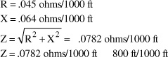
25. 3 ohms, 22 ohms, 88 volts, 66 volts, 5 ohms
26. 69 horsepower
27. 1800 revolutions per minute
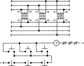
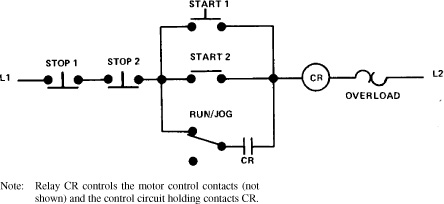
28. Diagram for Question 28.
I. Problems
Problem 1. See Detailed Calculations in Appendix B
Problem 2. See Detailed Calculations in Appendix B
Problem 3.
25-horsepower motor
FLA = 34 amperes (Table 430.250)
Conductor ampacity = 1.25 × 34 A = 42.5 A (430.22)
Branch-circuit protection = 3 × 34 A = 102 A; use 110-ampere fuse (Table 430.52) (240.6)
Running overcurrent = 1.25 × 34 A = 42.5 A [430.32(A)(1)]
Controller and disconnect: 25-horsepower rating (430.83)
30-horsepower motor
FLA = 40 amperes (Table 430.250)
Conductor ampacity = 1.25 × 40 A = 50 A (430.22)
Branch-circuit protection = 1.5 × 40 A = 60 A (Table 430.52)
Running overcurrent = 1.15 × 40 A = 46 A [430.32(A)(1)]
Controller and disconnect: 30-horsepower rating (430.83)
Feeder Circuit
Ampacity = 1.25 × 40 A + 40 A + 34 A = 124 A (430.24)
Feeder protection = 110 A + 40 A + 40 A = 190 A; use 175-ampere fuse [430.62(A)]
Problem 4. 9 feet [Table 110.34(E)]
Problem 5.
From Table 9, Chapter 9
Problem 6.
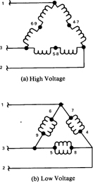
(a) 40-hp, 230-volt, three-phase motor
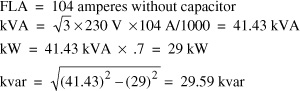
(b) Current = 29 kW![]() × 230 V = 72.8 A (after correction) Running overcurrent device = 1.25 × 72.8 A = 91 A [430.32(A)], (460.9)
× 230 V = 72.8 A (after correction) Running overcurrent device = 1.25 × 72.8 A = 91 A [430.32(A)], (460.9)
(c) Motor conductors = 1.25 × 10⁴ A = 130 A (minimum)
Capacitor current = 29.59 kvar/![]() × 230 V = 74.3 A
× 230 V = 74.3 A
Capacitor conductors = 1.35 × 74.3 A = 100.3 A minimum) (460.8)
Final Examination No. 3
I. (True or False)
1. T [90.2(A)]
2. F [210.8(A)(6)]
3. T [210.52(B)]
4. F [210.11(C)]
5. T (230.43)
6. T (250.140)
7. F (250.8)
8. T (590.6)
9. F (356.10)
10. T [430.52(C) Ex No. 1]
11. T [625.29(C)]
12. F [680.22(A)(3)]
II. (Multiple Choice)
1. (b) [210.19(A)]
2. (a) [210.52(A)]
3. (b) [210.52(C)(3)]
4. (a) [220.43(B)]
5. (c) (422.18, 314.27(D))
6. (c) (424.35)
7. (a) [Table 430.52]
8. (b) [525.5(B)]
9. (b) (680.2)
10. (b) (Annex C)
Final Examination No. 4
I. Fill in the Blank and Multiple Choice
1. Article 100
2. Identified [110.14(A)]
3. feet [110.26(A)]
4. white or gray [200.10(D)]
5. No [210.8(A)]
6. 10 feet [210.52(H)]
7. 1 VA/ft2 [220.14(K)]
8 70% [220.61(B)]
9. 12 feet [230.24(B)]
10. No (240.6)
(Multiple Choice)
1. (b) (210.3)
2. (b) (430.22)
3. (b) [220.82(C)]
4. (a) (240.4)
5. (c) [210.52(A)]
6. (d) [210.70(A)]
7. (b) [200.6(B)]
8. (b) [344.24, Table 2 Ch.9]
9. (b) (408.5)
10. (b) [450.3(B)]
11. (a) [422.48(B)]
12. (b) (430.232)
13. (b) [680.22(B)]
14. (a) (501.15)
15. (b (700.4)
II. Problem 1. See Detailed Calculations in Appendix B
DETAILED CALCULATIONS
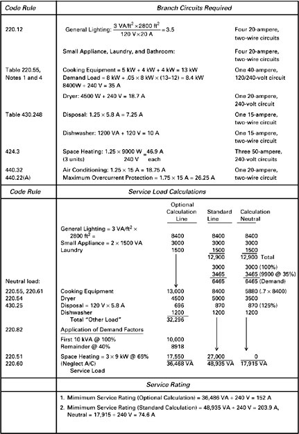
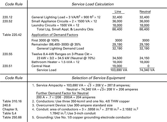
4-1.2 Quiz Problem 1
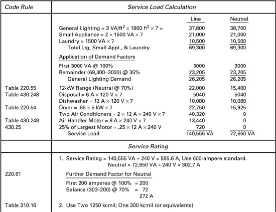
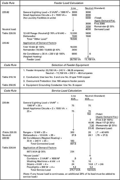
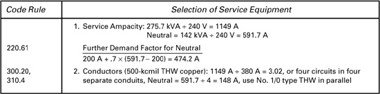
4–2.2 Quiz Problem 1
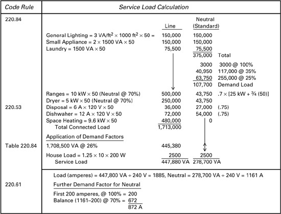
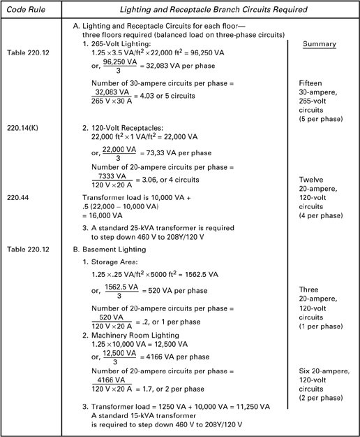
4–3 Quiz Problem 1
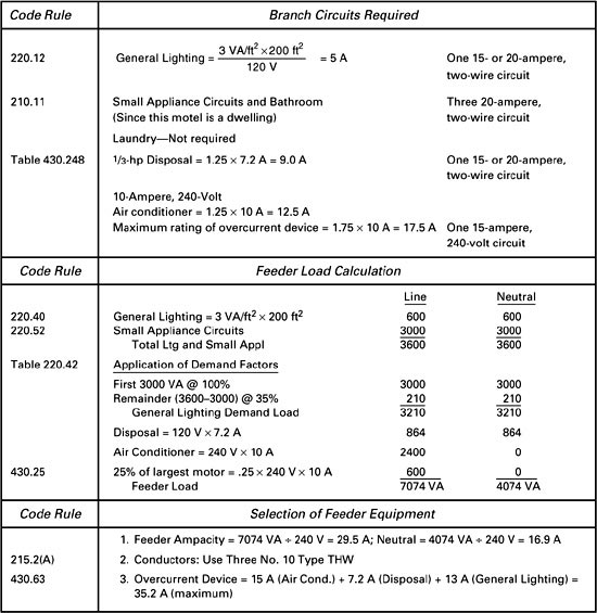
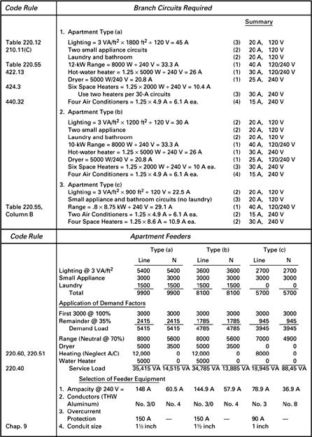
Test Chapter 4 Problem 1
Test Chapter 4 Problem 2
Test Chapter 4 Problem 3
Test Chapter 4 Problem 4
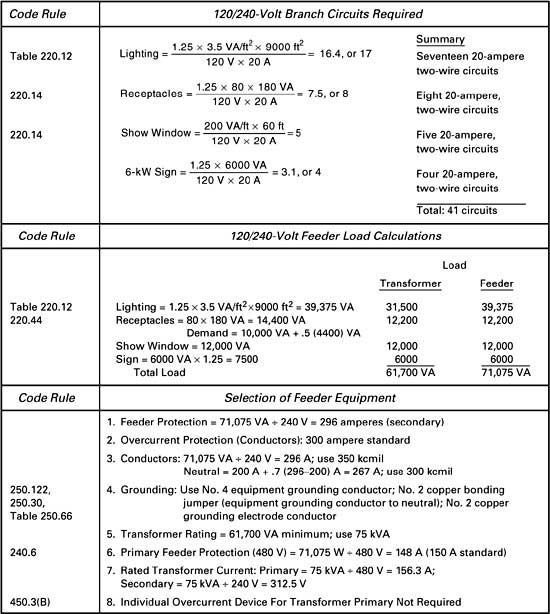
5–1 Quiz Problem 1
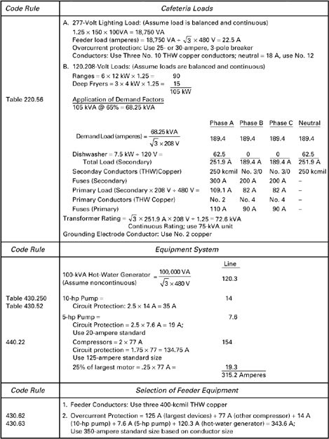
5–2 Quiz Problem 1
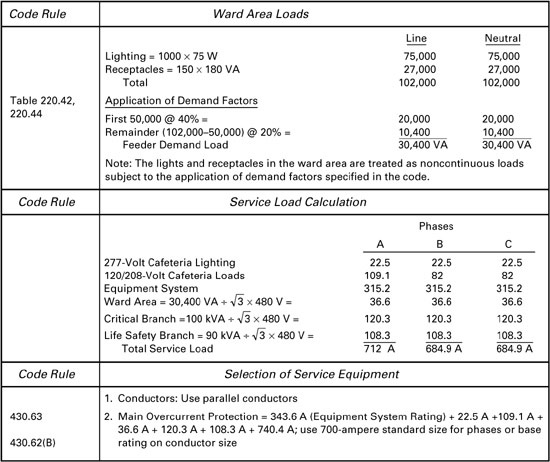
5–2 Quiz Problem 3
5–3 Quiz Problem 1
Test Chapter 5 Problem 1
Test Chapter 5 Problem 2

Test Chapter 5 Problem 3
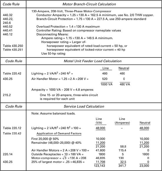
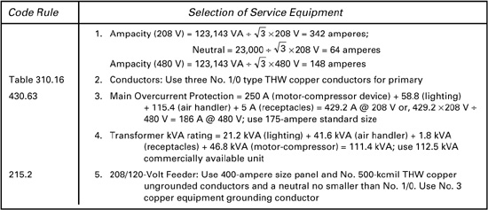
Final Examination No. 1 Problem 1

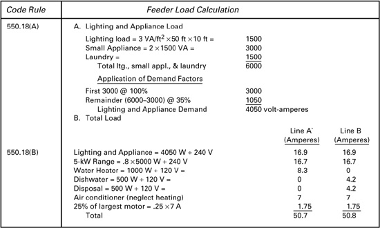
Final Examination No.1 Problem 6
Final Examination No.2 Problem 1
Final Examination No.2 Problem 2

Final Examination No.4 Answer Problem 1 Open Book 1 Hour