Chapter 2
Services, Feeders, and Branch Circuits
This chapter presents an introduction to the wiring design rules and related calculations used to determine electrical capacities and ratings of conductors and equipment required for the wiring systems in dwelling, commercial, and industrial occupancies. The material presented is grouped according to the three major elements of a premises wiring system: (a) services, (b) feeders, and (c) branch circuits. The utility company’s power distribution system will also be described briefly in order to discuss the entire electrical system.
The Code rules concerned with the electrical capacity of interior or premises wiring systems govern the design of these systems. The minimum or maximum size or rating of each element in the system as appropriate is determined by the applicable Code rule. In most cases, the Guide provides tables that summarize these design rules and gives references to the Code rules from which the tables were taken. These tables, and other Code tables not repeated here, allow the selection of the proper conductors and other equipment which make up the system.
ARTICLE 100
The Code definitions for electrical terms should be studied carefully since the Code rules are very specific for each element of the wiring system.
The sample design cases which are presented are summarized by figures and tables. These usually include a simplified electrical diagram of the example, the calculations, and the Code references. Examples in this chapter do not cover motor loads or continuous loads, which are treated in Chapter 3.
2–1 The Electrical System
230.2*
*References in the margins are to the specific applicable rules and tables in the National Electrical Code.
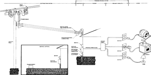
The electrical system to supply an occupancy consists of the distribution system and the premises wiring system according to the Code. The premises wiring system extends from the connection to the distribution system to the equipment to be supplied. The Code considers the premises wiring system to begin at the service for a building. Each building (with a few exceptions) has one service that supplies the interior electrical equipment referred to as the electrical load or simply as the load. The service may supply feeder circuits if they are required for the electrical system. The circuits which extend from the service or feeder and supply the load are branch circuits. The Code has special rules that apply to each portion of the premises wiring system.
Figure 2–1 illustrates a typical electrical system. The various elements of the premises wiring system are defined according to the Code definitions. These definitions serve as a basis for discussing wiring systems in the Guide.
Figure 2–1. Typical Electrical System
90.2
The distribution system begins at the generating station or distribution substation operated by the utility company. The distribution system supplies electrical power to each customer through transmission lines normally operating at relatively high voltages, a typical example being 138,000 volts. Transformers at or near the customer’s location step down the supply voltage to the value required by the customer’s premises wiring system. This reduced voltage is referred to as the service voltage and may typically range from 13,800 volts (for special industrial services) to the common 240-volt or 120-volt, single-phase service. The customer may install additional transformers if several different voltages are required or if both single-phase and three-phase loads are to be supplied. That portion of an electrical system installation under the exclusive control of the electrical utility company is not covered by the Code; however, the transformers supplied by the customer, as well as all conductors connected to or derived from the supply system, must meet Code requirements.
240.4
240.21
The premises wiring system extends from the service connection to the main supply to the outlets for the equipment. The Code requires that every conductor be protected against excessive current that could damage the conductor. The protection, in the form of an overcurrent protective device such as a fuse or circuit breaker, must, in most cases, be located where the conductors are electrically connected to their source of supply. Thus, each feeder and branch circuit in the premises wiring system must be protected. The service enclosure and the feeder panel shown in Figure 2–1 enclose the overcurrent protective devices for these circuits.
ARTICLE 100
The Code defines the service as the conductors and equipment which deliver energy from the supply system to the wiring system of the premises served. The service conductors extend from the main supply or a transformer to the service equipment. The Code considers the service conductors to consist of the service drop (or service lateral for underground conductors) and the service-entrance conductors. The distinction is important since the Code provides separate rules for each portion of the service circuit.
230.1
230.40
The service-entrance conductors connect the service drop or service lateral to the service equipment. The service equipment consists of the main overcurrent protection for the entire premises wiring system and the means to disconnect all conductors in a building from the service-entrance conductors. These devices, as well as overcurrent devices protecting any feeder circuits, are usually enclosed in the service enclosure.
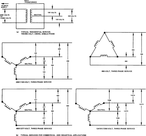
The typical services are shown schematically in Figure 2–2. The most common residential service is 120/240 volts, single-phase. Commercial and industrial establishments require three-phase services in many cases. The common 208Y/120-volt service supplies both 208-volt, three-phase loads such as motors and 120-volt, single-phase loads. Motor loads and 277-volt fluorescent lighting loads can be supplied by a 480Y/277-volt service. A high-voltage 12,470Y/7200-volt service would be used for special industrial applications.
Figure 2–2. Typical Service Configurations
Feeder circuits are primarily used in industrial and commercial occupancies. As shown in Figure 2–1, the feeder conductors extend from the service equipment enclosure to a feeder panel, or similar unit, that contains overcurrent protective devices for a group of branch circuits. The feeder conductors themselves are protected by circuit breakers or fuses located in the service equipment enclosure.
Branch circuits extend from the final overcurrent device protecting the circuit to the outlets for lights, appliances, and other equipment. In one-family dwellings branch circuits usually originate at the overcurrent protective device in the service equipment enclosure since feeder circuits are seldom used in such occupancies.
QUIZ 2–1 | 1. Draw a diagram showing the difference between the service drop, service lateral, and service-entrance conductors. 2. What are the standard services provided by the utility company in your area? 3. Describe the premises wiring system for a one-family dwelling. |
2–2 Services
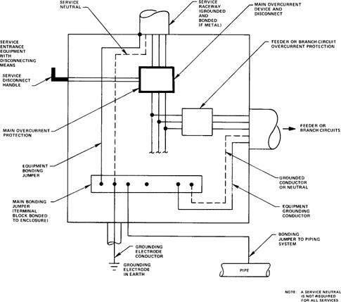
This section presents rules and related calculations for determining sizes and ratings of the various conductors and equipment required by the Code to be included in each service installation. The elements of the service installation to be discussed are depicted in Figure 2–3.
Figure 2–3. Service Equipment Elements
230.43
230.90
The service-entrance conductors are normally enclosed in a service raceway such as conduit. The conductors terminate at the service disconnecting means, which is usually a switch or circuit breaker. The service or main overcurrent protection is a set of fuses or a circuit breaker that protects the service-entrance conductors. Each metallic part of the service must be bonded together by an equipment bonding jumper.
250.24
250.28
250.104
If one conductor of the circuit, such as the neutral conductor, is grounded, a grounding electrode conductor that connects the grounded conductor to a grounding electrode is required. Each feeder circuit may require an equipment grounding conductor to ground the noncurrent-carrying metal parts of equipment. If this is the case, the main bonding jumper is used to electrically connect the equipment grounding conductor, the service-equipment enclosure, and the grounded conductor of the system. In Figure 2–3, the terminal block bonded to the service enclosure serves as the main bonding jumper. As shown in Figure 2–3, the metal water piping system of the building must be bonded to the grounding electrode conductor by a bonding jumper.
Each conductor, the disconnecting means, and the overcurrent protective device must satisfy Code rules which specify the size or rating as appropriate for the element. These rules form the basis for the electrical design of services.
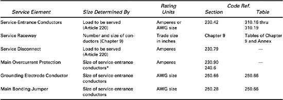
2–2.1 General Design Rules for Services
Table 2–1 defines for each element of the service those characteristics which are important in electrical design. The size of the conductors and equipment is determined by the Code rules and Code tables referenced in Table 2–1. For example, the size of the service-entrance conductors is given either as current-carrying capacity in amperes or American wire gauge (AWG) size and is determined by the load to be served. The electrical load must be computed in amperes to determine the proper size of the conductors according to the Code rules that apply. The size of the service-entrance conductors then determines the size or ratings of the main overcurrent protective device, the grounding electrode conductor, and the main bonding jumper. The service raceway trade size depends on the number of conductors in the service as well as the size of the conductors. Finally, the rating of the service disconnecting means depends on the load to be served in amperes. The calculations of this subsection determine the electrical load in amperes when the load in watts is given, as is normally the case. Each element of the service is then chosen based on the Code references shown in Table 2–1.
Table 2–1. Summary of Requirements for Service Equipment and Conductors
ARTICLE 230
250.24
TABLE 250.66
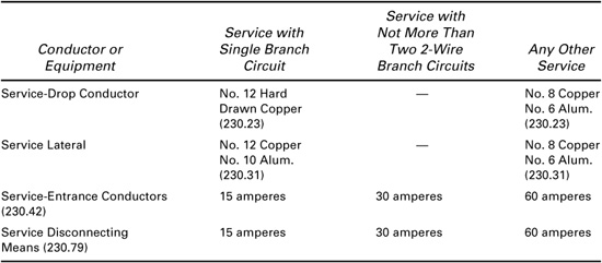
Minimum Service Ratings. The Code specifies a minimum size or minimum ampacity for service conductors and the service disconnecting means as shown in Table 2–2. The smallest service rating is 60 amperes unless only one or two branch circuits are served. The minimum sizes or current ratings do not apply to the grounded conductor of a service. The grounded conductor may not be smaller than the grounding electrode conductor which, for an alternating-current system, is based on the size of the service-entrance conductors.
Table 2–2. Minimum Sizes or Ampacities for Service Equipment and Conductors
230.42, 230.79
In a one-family dwelling the minimum service rating is 100 amperes. This is one of many cases in which the Code specifies rules that depend on the type of occupancy.
ARTICLE 230 PART VIII
230.202
If the service voltage is greater than 600 volts, the special rules that apply to higher voltage circuits must be used. The minimum service conductor sizes are given in the Code.
ARTICLE 430 PART IX
Service Disconnecting Means and Overcurrent Protection. The main or service disconnecting means disconnects all conductors in a building from the service-entrance conductors. The service disconnecting means is not intended to protect equipment, as the overcurrent protective device does, and it is not intended to be opened to interrupt short-circuit currents; therefore, a minimum size is specified no smaller than that listed in Table 2–2. Normally, the service disconnecting means is rated in amperes and has the same rating as the service-entrance conductors. If motors are supplied, special rules must be applied.
230.91
240.21
230.94
240.4
240.6
The service overcurrent protective device must be an integral part of the service disconnecting means or be located immediately adjacent to it. Although the overcurrent protection is at the load end of the service-entrance conductors, an exception to the rule that requires conductors to be protected at the supply end is made for service-entrance conductors. For nonmotor loads, the overcurrent protection device must not have a higher ampacity rating than the conductors except that the next higher standard-rated overcurrent device (up to 800 amperes) may be used if the ampacity of the conductor does not correspond to a standard ampere rating.
250.66
Service Grounding and Bonding. The grounding electrode conductor connects the grounding electrode to the grounded conductor (or neutral) for grounded systems. When the grounding electrode is not a made electrode,1 the minimum size of the grounding electrode conductor is determined by the size of the largest service-entrance conductor. The connection to a made electrode is not required to be larger than a No. 6 copper wire or equivalent. Other rules apply where the connection is to a concrete-encased electrode or a ground ring.
1A made electrode is constructed of metal rods or plates. The metal structure of a building or the metal water piping system are other types of grounding electrodes.
250.102
250.104
Several equipment bonding jumpers may be required at the service to bond or electrically connect service conduit to the service enclosure or to bond the grounding electrode to the water piping system in a building. The size of these jumpers is determined by the size of the service conductors. Equipment bonding on the load side of the service overcurrent devices requires a jumper size based on the setting of the overcurrent devices, not the conductor size.
Design Technique and Rules. To determine the rating or size of the service elements, the load current is first determined and then the size of the ungrounded and grounded service-entrance conductors is chosen based on the load current. The other elements, including the service raceway, disconnecting means, overcurrent protection, and grounding and bonding conductors, are then selected.
310.15
The ampacity of the conductors depends on the type of conductor material and the type of insulation. For a given AWG size, copper conductors will carry safely more current than aluminum conductors because copper has a lower resistance. The insulation, which can be damaged by excessive heat, determines the ampacity of a given conductor. If the conductor is in a raceway or cable and not free in the air, its ampacity is reduced. The Code provides tables which relate AWG size to the ampacity based on the type of material and the type of insulation. Individual tables are provided for conductors in a raceway or cable and for conductors in free air. All of these factors must be considered in order to select the table that fits the situation.2
2For calculation purposes, all conductors are assumed to be in a raceway or cable unless otherwise stated in the Guide. It is also assumed that the conductors and the overcurrent protective device for the circuit are used within their temperature rating.
2–2.2 Sample Service Calculation
An example of the calculations required for designing a simple service installation is given in Figure 2–4. The applicable rules for determining the size or rating of the various elements of the service are contained in the Code references cited in that figure. In following the example given in the Guide, the Code book should also be used and each Code section should be read at the time it is referenced by the Guide.
Figure 2–4. Sample Service Calculation
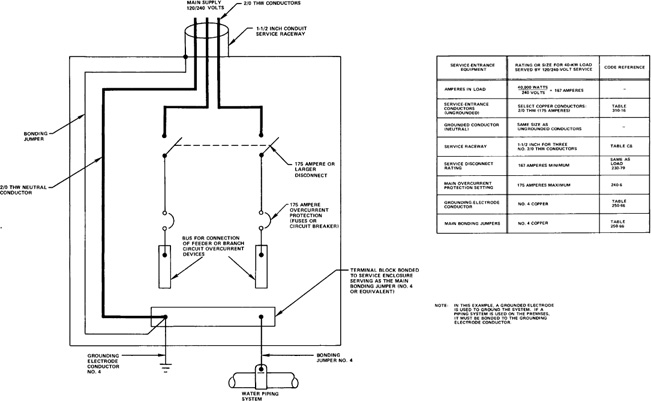
The service is chosen to be a 120/240-volt, single-phase service. A load of 40,000 volt-amperes is to be served for which the size or rating of all the elements of the service must be selected. Type THW copper conductors in conduit are selected for the service-entrance conductors.
First, the load in volt-amperes (or watts) is converted to amperes.3 The load current is
3For loads with a power factor of less than 1, the volt-ampere rating should be used for load calculations. For purely resistive loads (i.e., power factor equal to 1), watts are equivalent to volt amperes. Refer to Section 3–2.5 and to Chapter 13 of the Guide for a discussion. Fractions of an ampere less than 0.5 may be ignored in calculations.
220.5
![]()
TABLE 310.16
for this single-phase service. The service-entrance conductors must have an ampacity of at least 167 amperes. Type THW copper conductors of AWG size No. 2/0 (175 amperes) are required according to the Code table of ampacities for these conductors. The service is a three-wire circuit consisting of the two ungrounded conductors and a neutral conductor.
CHAPTER 9 TABLE 1
ANNEX C TABLE C8
The service raceway must conform to the Code rules for percent of conduit fill. Since there are three conductors in the conduit, their cross-sectional area, including insulation, must not exceed 40% of the total cross-sectional area of the conduit. This is specified in the Code to prevent damage to the conductors when they are pulled in during installation of the wiring system. Since all of the conductors are the same size, the Code table “Maximum Number of Conductors in Rigid Metallic Conduit” may be used to find the required conduit size. According to that table, three No. 2/0 THW conductors are allowed in a 1½-inch trade size conduit.
230.79
230.90
240.4
The service disconnecting means and the overcurrent device can be sized according to the rating of the service-entrance conductors. The disconnecting means must have a rating not less than the size of the load, while the overcurrent device cannot be rated higher than the ampacities of the conductors in the example given. A 175-ampere disconnecting means would satisfy the first requirement. The overcurrent protective device may be rated at 175 amperes also since this corresponds to the conductor ampacity.
TABLE 250.66
The Code table “Grounding Electrode Conductor for AC Systems” determines the size of the grounded electrode conductor and the main bonding jumper. The grounded electrode conductor and the main bonding jumper are sized as No. 4 copper because of the No. 2/0 service-entrance conductors.
2–2.3 Three-Phase Services
In principle, the calculations for three-phase services are the same as for single-phase services when the loads between phase conductors or between phase conductors and neutral are balanced. The load in amperes on each phase conductor is given by the formula:
![]()
For example, a 40-kilovolt-ampere load evenly distributed on a 208Y/120-volt, three-phase service (13.3 kilovolt-amperes per phase) places a line load in amperes on each phase conductor of:
![]()
230.90
This is a four-wire service and requires either three fuses (one in each ungrounded conductor) or a three-pole circuit breaker for the main overcurrent protection.
QUIZ 2–2 | 1. What are the minimum size requirements for service-drop conductors? 2. What is the minimum rating for service-entrance conductors supplying a one-family dwelling? 3. What is the purpose of the main overcurrent device? 4. What is the purpose of the main disconnecting means? 5. Describe each item and its rating in the service to a home having a 10-kilovolt-ampere load. 6. Draw a diagram showing the grounding electrode conductor, bonding jumper, and the grounded conductor for a standard service. 7. The size of the grounding electrode conductor depends on which portion of the service? 8. What is the maximum size required for a grounding electrode conductor connected to a made electrode? 9. What is the minimum rating for the disconnecting means for a one-family dwelling? 10. Which service conductor is intentionally grounded? |
(Open-Book) | 1. What is the ampacity of the conductors and the size of the service raceway for THW copper conductors if the service is 120/240 volts and supplies a load of 46 kVA? 2. What is the conduit size in problem 1 above if THHN conductors are used? (Hint: These are 90°C conductors as specified in the appropriate Code table.) 3. Compare the ampacity of the conductors and the size of the service conduit for THW copper conductors if the service is 120/240 volts in the following cases: (a) 10-kilovolt-ampere load on three branch circuits (b) 20-kilovolt-ampere load (c) 20-kilovolt-ampere load in a one-family dwelling (d) 100-kilovolt-ampere load 4. Three No. 2/0 THW copper conductors in a 120/240-volt service will serve what load in volt-amperes? 5. Select the size of the standard fuse protection that would be used in the following cases: (a) 900-ampere conductors (b) 130-ampere load 6. If the service conductors are No. 2 THW copper and the main circuit breaker is set at 115 amperes, determine the size required for the following: (a) The jumper bonding the service conduit to the neutral terminal block (b) The grounding electrode conductor (c) The equipment bonding jumper to the water piping system 7. Determine the required size of type THW copper conductors in conduit to supply a 40-kilovolt-ampere load if the voltage is 480 volts, three-phase. |
2–3 Feeders
This section presents the basic techniques involved in the design of feeder circuits and introduces the concept of feeder demand factors.
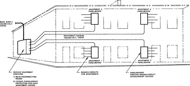
Feeder circuits are primarily used in apartment buildings and commercial and industrial occupancies. A typical feeder circuit system is illustrated in Figure 2–5 in which the service supplies separate feeders to each of four apartment units. The feeder circuits originate at the service enclosure and supply panelboards containing overcurrent protective devices for branch circuits. Each feeder circuit conductor is protected by a circuit breaker or set of fuses located within the service enclosure.
Figure 2–5. Typical Feeder Arrangement for an Apartment Complex
2–3.1 General Feeder Design Rules
To determine the size or rating of each element of a feeder circuit, the load is calculated; then the size or rating of conductors, raceways, and the overcurrent protective device is determined based on the results of the load calculations. The calculations for feeders are similar to those for services. Also, the main bonding jumper and the grounding electrode conductor are used only for services.
If several feeders originate at a service, the conductor sizes and the rating of the overcurrent protective device for each feeder circuit should first be calculated separately before the load for the entire service is calculated. In the apartment shown in Figure 2–5, the load for each apartment would be calculated to determine the feeder rating. The service capacity is determined by the total load from all the apartments.
215.2
Feeder conductors must have an ampacity not lower than that required to supply the computed load. As was the case with services, minimum sizes for feeders are specified by the Code under certain conditions.
The feeder conductor ampacity shall not be lower than that of the service-entrance conductors if the feeder conductors carry the total load supplied by service-entrance conductors of 55 amperes or less.
310.15(B)
The Code allows a reduction in the size of feeder conductors for a given feeder rating in individual dwellings or mobile homes.
225.6
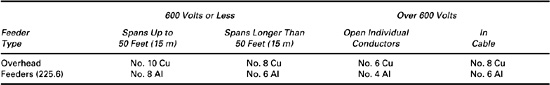
The Code also requires that overhead feeders meet the minimum size requirements shown in Table 2–3.
Table 2–3. Minimum Sizes for Overhead Feeder Conductors
220.40
Feeder Calculations. The feeder load in amperes is calculated from the total load in watts to determine the minimum rating of the feeder circuit. Since one service may supply several feeders, the load for each feeder (if the loads are different) must be determined. The feeder load is the sum of the loads on the branch circuits when no demand factors are applied. The feeder conductor ampacity, the raceway size, the rating of the overcurrent protective device, and the size of the equipment grounding conductor are calculated to complete the feeder circuit design. An example will serve to illustrate the calculation techniques involved.
Assume the feeder circuits of Figure 2–5 are 120/240-volt circuits that supply a 10-kilovolt-ampere computed load in each apartment. The feeder capacity for each feeder must be at least
![]()
TABLE 310.16
TABLE C8
240.4
240.6
TABLE 250.122
250.118
The minimum standard rating of the feeder circuit is 45 amperes. If type THW copper conductors in conduit supply the apartments, size No. 8 is required according to the Code table of ampacities. The conduit to enclose three No. 8 THW conductors must be at least ¾ inch, as specified in the Code table “Maximum Number of Conductors in Rigid Metallic Conduit.” A standard 45-ampere or 50-ampere overcurrent device could be used to protect the circuit.4 The Code table “Minimum Size Equipment Grounding Conductors for Grounding Raceway and Equipment” specifies a No. 10 copper conductor for the equipment grounding conductor since the overcurrent device is rated at less than 60 amperes. In this installation the conduit could serve as the equipment grounding conductor, in which case an additional conductor would not be required.
4In practice, a 60-ampere device may be more readily available. If the device is marked as suitable for 75°C rated conductors, No. 6 THW copper conductors could be used. An overcurrent device marked for 60°C conductors would require No. 4 THW conductors.
The load given in this example is referred to as the demand load. For a feeder, this is not necessarily the same value as the load that is directly connected to the feeder through the branch circuits when a feeder demand factor is allowed.
220.40
Feeder Demand Factors. In most cases, the feeder ampacity must be sufficient to supply power to the total connected load. Under special conditions, however, the Code allows the feeder circuit ratings to be reduced (or derated) according to specified demand factors. The maximum demand load for the feeder is
maximum demand = connected load × demand factor
The Code specifies the demand factors for each situation in which they may be used. The Code rules are very precise and demand factors must not be applied unless they are specifically allowed.
TABLE 220.54
As an example of the use of a demand factor which is allowed only in dwellings such as apartment buildings, Figure 2–6 shows ten 5-kilowatt electric clothes dryers connected to a single-phase 240-volt feeder. The connected load is 50 kilowatts (10 × 5 kilowatts) and would require a feeder ampacity of 50 000 watts/240 volts = 208 amperes. Since all the dryers would not normally be operating simultaneously at their full-rated load, the Code table “Demand Factors for Household Electric Clothes Dryers” allows a demand factor of 50% (.50) to be applied. The demand load is then
Figure 2–6. Example of Demand Factors Application
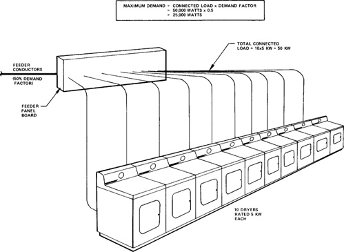
demand load = 10 units × 5000 W × .50 = 25,000 W
The required feeder ampacity must be only 25,000 watts (volt-amperes)/240 volts = 104 amperes in this case.
220.61
The Code allows a demand factor to be applied to the feeder neutral load in certain cases. Normally, the feeder neutral load is considered to be the maximum connected load between the neutral and any one ungrounded conductor. If the load is balanced between the ungrounded conductors and the neutral, the neutral load is then the same as the load on any one ungrounded conductor. If the feeder is a three-wire, single-phase feeder or a four-wire, three-phase feeder, the neutral load may be reduced if the load exceeds 200 amperes and the load does not consist of nonlinear loads as described in Chapter 3 of this Guide. The Code specifies a demand factor of 70% (.70) for the neutral current of a load that exceeds 200 amperes. Thus, if the neutral load is computed to be 450 amperes, the neutral demand load is
![]()
This demand factor applies to any feeder neutral that meets the requirements stated above, regardless of the type of occupancy served.
430.24
It is important to note that reductions based on demand factors are not always possible, i.e., the application of demand factors depends on the type of load being served by the feeder and on the type of occupancy involved. When a feeder supplies only motor circuits, for example, the application of demand factors is generally not permitted; in fact, the feeder circuit ampacity will be required to be greater than the sum of the full-load current ratings of all the motors connected to the feeder as described in Chapter 3.
2–3.2 Sample Feeder Calculation Using Demand Factors
Figure 2–7 summarizes a feeder calculation based on a 110-kilowatt connected load and a 35% feeder demand factor. Type THW copper conductors are used for the 120/240-volt feeder circuit that is enclosed in rigid metal conduit.
Figure 2–7. Sample Feeder Calculation
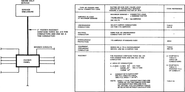
The demand load in amperes is
This requires size No. 2/0 THW copper conductors since they will be enclosed in a raceway (conduit). The conductors are capable of carrying 175 amperes.
240.4
The overcurrent device is selected to be 175 amperes, which protects the conductors and corresponds to a standard rating.
250.118
TABLE 250.122
The equipment grounding conductor is required unless the raceway is metal and of a type allowed to be used for grounding. It electrically connects the noncurrent-carrying metal portions of equipment to the grounded conductor and the grounding electrode conductor at the service. A No. 6 copper conductor is selected based on a 175-ampere overcurrent protective device.
CHAPTER 9 TABLE 1
CHAPTER 9 TABLE 5
The conduit must enclose three No. 2/0 conductors and the No. 6 equipment grounding conductor. The total area of the conductors must not exceed 40% of the cross-sectional area of the conduit since more than two conductors are enclosed. To determine the area of the conductors, the Code table “Dimensions of Insulated Conductors and Fixture Wires” must be used since several different size conductors are enclosed. Column 5 of that table gives the area of type THW conductors as follows:
![]()
CHAPTER 9 TABLE 4
The conduit must enclose conductors with an area of .8598 square inches and be 40% or less full. The Code table “Dimensions and Percent Area of Conduit and Tubing” relates the trade size of conduit to the 40% area in square inches. The 40% area of the conduit must be at least .8598 square inches to meet the Code requirement. A 2-inch conduit with a 40% fill area of 1.34 square inches is the smallest permissible size in this case.
QUIZ 2–3 | 1. A 120/240-volt feeder supplies two 120/240-volt 20-ampere branch circuits. What is the minimum size feeder conductor allowed? 2. What size feeder conductors are required if the feeder carries the total load of a service whose conductors are size No. 8 (THW copper)? 3. A 480-volt feeder circuit is run as an overhead span 100 feet in length. What is the minimum size of the feeder conductors? 4. Define feeder according to the Code. 5. Describe the important differences between feeders and services. 6. What is the maximum demand load if a feeder supplies a connected load of 100 kilowatts with a demand factor of 50%? |
(Open-Book) | 1. A 120/240-volt feeder supplies a 30-kilovolt-ampere load. Find the following: (a) The line load in amperes (b) The size of THW copper conductors to carry the load (c) The total cross-sectional area of the wires (d) The required conduit size if the conduit is used for equipment grounding 2. If the 30-kVA load in problem 1 is supplied by a 480Y/277-volt feeder, what are the answers to the questions of problem 1? Compare the two results. 3. A 120/240-volt feeder supplies a load of 100 kVA. Find the following: (a) The line load in amperes (b) The required ampacity of the neutral after derating (c) The size of the ungrounded conductors and the neutral conductor if THW copper conductors are used 4. A four-wire, three-phase feeder is required to supply a 1000-ampere load. What is the required ampacity of the neutral conductor? |
2–4 Branch Circuits
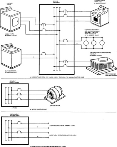
The branch circuit is that portion of the premises wiring system that extends from the last overcurrent device protecting the branch-circuit conductors to the outlets supplying the utilization equipment connected to the branch circuit. Normally, the overcurrent device is a set of fuses or a circuit breaker located in a panelboard supplied by a feeder or service. In a one-family dwelling the branch-circuit overcurrent devices are located in the service equipment enclosure. Typical branch circuits supplied from a feeder panelboard are illustrated in Figure 2–8. Figure 2–8(a) shows a wiring system that might be found in a modern home. The large appliances have individual branch circuits and the lights and receptacles are supplied by a number of 15- or 20-ampere circuits. Figure 2–8(b) and (c) show circuits typical of industrial installations. The lighting circuits and the receptacle circuits are supplied by the 120/240-volt panel and the motor by a separate 480-volt panel.
Figure 2–8. Typical Branch Circuits
ARTICLE 100 DEFINITIONS
The Code distinguishes branch circuits according to their use, and, in some cases, different rules apply to appliance branch circuits, general-purpose branch circuits, or individual branch circuits. The term utilization equipment is taken to be the same as the load to be served. The Code implies that the load is supplied at an outlet, which is simply a connection to supply the conductors. A receptacle outlet is used for the common cord and plug attachment to a branch circuit.
2–4.1 General Branch-Circuit Design Rules
220.55
ARTICLE 630
Unlike services that supply the total electrical requirements for a building, or feeders that supply portions of a building, the branch circuit provides electrical energy to specific equipment or loads such as room lighting, electric ranges, or motors. With few exceptions, the branch-circuit rating must be as great or greater than the full-load current rating of the equipment attached to the branch circuit. Demand factors, such as are applied to feeders or services, are generally not applicable to branch circuits. (Exceptions to this rule include household electric ranges and equipment that operates intermittently.)
210.3
Rating of Branch Circuits. A branch circuit is rated according to the rating or setting of the overcurrent device protecting the circuit. For example, if a 15-ampere circuit breaker protects a circuit of No. 10 THW conductors that have a 35-ampere rating, the branch circuit is still rated at 15 amperes. The use of the larger conductor in this case may have been necessary in order to reduce an excessive voltage drop from the feeder or service to the equipment being supplied. The 15-ampere circuit breaker may have been required to protect a small appliance; a larger circuit breaker would not have been permitted.
210.3
210.23
An individual branch circuit may have any rating and it may supply any load for which it is rated.
210.3
If two or more outlets are supplied by a branch circuit, the rating of the branch circuit is restricted to those ratings listed in the Code, which are 15, 20, 30, 40, and 50 amperes. (An exception is provided for certain industrial installations.)
210.19
430.22
TABLE 310.16
240.4
Ampacity of Branch-Circuit Conductors. Except for a branch circuit supplying a motor, branch-circuit conductors must have an ampacity not less than the rating of the branch circuit as determined by the overcurrent protective device and not less than the maximum load to be served. The Code specifies the minimum size for branch-circuit conductors as No. 14. The frequently used No. 14 THW copper conductors are suitable for such a circuit. Small conductors up to No. 10 are limited as to the branch-circuit rating.
210.23
Maximum and Permissible Loads. The load on a branch circuit cannot exceed the branch-circuit rating. As stated previously, an individual branch circuit may supply any load for which it is rated. When a load is supplied by branch circuits with two or more outlets, the load must be divided so that there is a sufficient number of branch circuits of the proper rating. Too many branch circuits, such as a separate circuit for each lighting fixture, would be impractical and uneconomical.
For certain loads, the Code defines a maximum rating for the branch circuit that will be used to supply the load. For example, standard lampholders may not be connected to a branch circuit having a rating in excess of 20 amperes. The total lighting load of standard lampholders must therefore be divided into a number of 15- or 20-ampere branch circuits.
The branch circuit is limited in the power it may supply to a load by both the specified voltage and current rating. For example, a 120-volt, 15-ampere single-phase branch circuit may supply a maximum load of
120 V × 15 A = 1800 VA
In the case of a three-phase branch circuit, the power that may be supplied to a load is
![]()
A three-phase, 480-volt, 15-ampere circuit may supply a maximum load of
1.732 × 480 V × 15 A = 12,470 VA
Multiwire Branch Circuits. A typical branch circuit for single-phase loads consists of two circuit conductors and an equipment grounding conductor. One circuit conductor is usually grounded as is the case with the commonly used 120-volt, two-wire circuit. If a circuit has two or more ungrounded conductors with a potential difference between them, and a grounded conductor with equal potential difference between it and each ungrounded conductor, it is referred to as a multiwire circuit. A typical multiwire circuit used for single-phase loads is the 120/240-volt, three-wire circuit.
A single three-wire circuit has a capacity equivalent to two two-wire circuits. Three-wire branch circuits, therefore, are frequently used to supply lighting and receptacle loads because of the cost factors involved, especially in commercial and industrial occupancies where large loads and long distribution distances are present.
A 120/240-volt, three-wire circuit with a 15-ampere rating can supply a total load of
240 V × 15 A = 3600 W
or twice the capacity of 1800 watts provided by a 120-volt, two-wire circuit with the same ampere rating.
210.4
Multiwire circuits may be used to supply only line to neutral loads except in the cases in which only a single load is supplied or in which all ungrounded conductors of the circuit are opened simultaneously by the branch-circuit protective device.
2–4.2 Branch-Circuit Calculation Techniques
The standard calculations for individual branch circuits include determining the conductor ampacity, the rating of the overcurrent device, the size of the equipment grounding conductor, and, finally, the conduit size (if used). The techniques involved are the same as those shown previously for services and feeder circuits.
When the load is given in kilovolt-amperes or watts, the load in amperes is easily calculated to determine the minimum required circuit rating. A 10-kilovolt-ampere load connected to a 120/240-volt branch circuit, for example, represents a load in amperes of
![]()
TABLE 310.16
TABLE 250.122
Once the load in amperes has been determined, each element of the branch circuit can be selected. The 120/240-volt circuit with a load of 41.7 amperes could use No. 8 THW copper conductors and an overcurrent protective device rated at 50 amperes or less. A No. 10 copper equipment grounding conductor would be required if other means of grounding were not used.
In the example, an individual branch circuit with a minimum rating of 45 amperes could supply the 10-kilovolt-ampere load. An individual branch circuit is normally used for such large single loads.
2–5 Other Design Considerations—Temperature Ratings
The design examples in this chapter explained the techniques used to select conductors, overcurrent protective devices, and raceways to contain the conductors. The conductors were chosen to carry the load and the overcurrent protective device was then selected to protect the conductors according to Code rules.
TABLE 310.16
110.14(C)
The conductors chosen for a particular circuit must not overheat due to the load current or other conditions of use. For example, No. 8 THW copper conductors in a raceway have a temperature rating of 75°C when carrying 50 amperes. There is a danger of damaging the insulation if more than this amount of current flows through the conductors.
However, the conductors must be chosen not only to protect conductor insulation from the damaging heating effects. In addition, the conductor temperature at a termination must not exceed the temperature rating of any device to which the conductor is connected.
TABLE 310.16
The temperature rating is important when circuit breakers are chosen as the overcurrent protective device for a circuit. For example, if the temperature rating of a breaker is 60°C, the current in the connected conductor must be limited so that this temperature is not exceeded at the terminations. Thus, the current in a No. 8 THW conductor must be limited to 40 amperes so that the connection to the breaker does not exceed the 60°C rating.
If a circuit breaker is marked as suitable for use with 75°C rated conductors, the conductors rated 75°C can be used at their full rated current as specified in the Code tables of allowed ampacities. Unless otherwise indicated, the design examples in this Guide assume that the overcurrent protective device protecting conductors in a circuit has the same temperature rating as the conductors. Thus, the No. 8 THW conductors carrying 50 amperes could be protected by a 50-ampere circuit breaker that is marked with a 75°C rating.