
13. Architectural Tactics and Patterns
I have not failed. I’ve just found 10,000 ways that won’t work.
—Thomas Edison
There are many ways to do design badly, and just a few ways to do it well. Because success in architectural design is complex and challenging, designers have been looking for ways to capture and reuse hard-won architectural knowledge. Architectural patterns and tactics are ways of capturing proven good design structures, so that they can be reused.
Architectural patterns have seen increased interest and attention, from both software practitioners and theorists, over the past 15 years or more. An architectural pattern
• is a package of design decisions that is found repeatedly in practice,
• has known properties that permit reuse, and
• describes a class of architectures.
Because patterns are (by definition) found in practice, one does not invent them; one discovers them. Cataloging patterns is akin to the job of a Linnaean botanist or zoologist: “discovering” patterns and describing their shared characteristics. And like the botanist, zoologist, or ecologist, the pattern cataloger strives to understand how the characteristics lead to different behaviors and different responses to environmental conditions. For this reason there will never be a complete list of patterns: patterns spontaneously emerge in reaction to environmental conditions, and as long as those conditions change, new patterns will emerge.
Architectural design seldom starts from first principles. Experienced architects typically think of creating an architecture as a process of selecting, tailoring, and combining patterns. The software architect must decide how to instantiate a pattern—how to make it fit with the specific context and the constraints of the problem.
In Chapters 5–11 we have seen a variety of architectural tactics. These are simpler than patterns. Tactics typically use just a single structure or computational mechanism, and they are meant to address a single architectural force. For this reason they give more precise control to an architect when making design decisions than patterns, which typically combine multiple design decisions into a package. Tactics are the “building blocks” of design, from which architectural patterns are created. Tactics are atoms and patterns are molecules. Most patterns consist of (are constructed from) several different tactics. For this reason we say that patterns package tactics.
In this chapter we will take a very brief tour through the patterns universe, touching on some of the most important and most commonly used patterns for architecture, and we will then look at the relationships between patterns and tactics: showing how a pattern is constructed from tactics, and showing how tactics can be used to tailor patterns when the pattern that you find in a book or on a website doesn’t quite address your design needs.
13.1. Architectural Patterns
An architectural pattern establishes a relationship between:
• A context. A recurring, common situation in the world that gives rise to a problem.
• A problem. The problem, appropriately generalized, that arises in the given context. The pattern description outlines the problem and its variants, and describes any complementary or opposing forces. The description of the problem often includes quality attributes that must be met.
• A solution. A successful architectural resolution to the problem, appropriately abstracted. The solution describes the architectural structures that solve the problem, including how to balance the many forces at work. The solution will describe the responsibilities of and static relationships among elements (using a module structure), or it will describe the runtime behavior of and interaction between elements (laying out a component-and-connector or allocation structure). The solution for a pattern is determined and described by:
• A set of element types (for example, data repositories, processes, and objects)
• A set of interaction mechanisms or connectors (for example, method calls, events, or message bus)
• A topological layout of the components
• A set of semantic constraints covering topology, element behavior, and interaction mechanisms
The solution description should also make clear what quality attributes are provided by the static and runtime configurations of elements.
This {context, problem, solution} form constitutes a template for documenting a pattern.
Complex systems exhibit multiple patterns at once. A web-based system might employ a three-tier client-server architectural pattern, but within this pattern it might also use replication (mirroring), proxies, caches, firewalls, MVC, and so forth, each of which may employ more patterns and tactics. And all of these parts of the client-server pattern likely employ layering to internally structure their software modules.
13.2. Overview of the Patterns Catalog
In this section we list an assortment of useful and widely used patterns. This catalog is not meant to be exhaustive—in fact no such catalog is possible. Rather it is meant to be representative. We show patterns of runtime elements (such as broker or client-server) and of design-time elements (such as layers). For each pattern we list the context, problem, and solution. As part of the solution, we briefly describe the elements, relations, and constraints of each pattern.
Applying a pattern is not an all-or-nothing proposition. Pattern definitions given in catalogs are strict, but in practice architects may choose to violate them in small ways when there is a good design tradeoff to be had (sacrificing a little of whatever the violation cost, but gaining something that the deviation gained). For example, the layered pattern expressly forbids software in lower layers from using software in upper layers, but there may be cases (such as to gain some performance) when an architecture might allow a few specific exceptions.
Patterns can be categorized by the dominant type of elements that they show: module patterns show modules, component-and-connector (C&C) patterns show components and connectors, and allocation patterns show a combination of software elements (modules, components, connectors) and nonsoftware elements. Most published patterns are C&C patterns, but there are module patterns and allocation patterns as well. We’ll begin with the granddaddy of module patterns, the layered pattern.
Module Patterns
Layered Pattern
Context: All complex systems experience the need to develop and evolve portions of the system independently. For this reason the developers of the system need a clear and well-documented separation of concerns, so that modules of the system may be independently developed and maintained.
Problem: The software needs to be segmented in such a way that the modules can be developed and evolved separately with little interaction among the parts, supporting portability, modifiability, and reuse.
Solution: To achieve this separation of concerns, the layered pattern divides the software into units called layers. Each layer is a grouping of modules that offers a cohesive set of services. There are constraints on the allowed-to-use relationship among the layers: the relations must be unidirectional. Layers completely partition a set of software, and each partition is exposed through a public interface. The layers are created to interact according to a strict ordering relation. If (A,B) is in this relation, we say that the implementation of layer A is allowed to use any of the public facilities provided by layer B. In some cases, modules in one layer might be required to directly use modules in a nonadjacent lower layer; normally only next-lower-layer uses are allowed. This case of software in a higher layer using modules in a nonadjacent lower layer is called layer bridging. If many instances of layer bridging occur, the system may not meet its portability and modifiability goals that strict layering helps to achieve. Upward usages are not allowed in this pattern.
Of course, none of this comes for free. Someone must design and build the layers, which can often add up-front cost and complexity to a system. Also, if the layering is not designed correctly, it may actually get in the way, by not providing the lower-level abstractions that programmers at the higher levels need. And layering always adds a performance penalty to a system. If a call is made to a function in the top-most layer, this may have to traverse many lower layers before being executed by the hardware. Each of these layers adds some overhead of their own, at minimum in the form of context switching.
Table 13.1 summarizes the solution of the layered pattern.
Table 13.1. Layered Pattern Solution
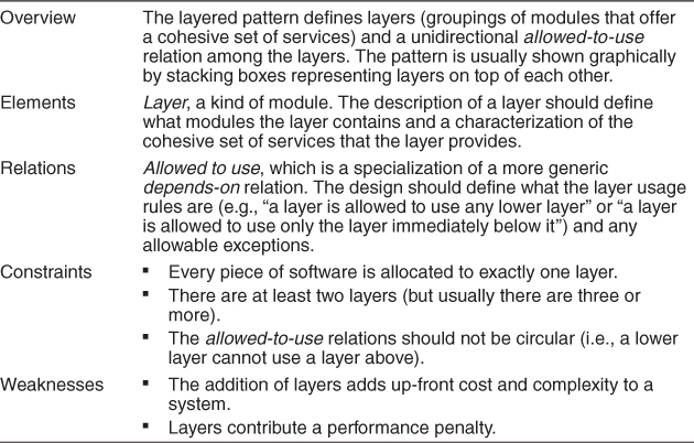
Layers are almost always drawn as a stack of boxes. The allowed-to-use relation is denoted by geometric adjacency and is read from the top down, as in Figure 13.1.
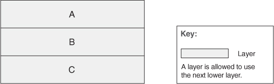
Figure 13.1. Stack-of-boxes notation for layered designs
A layered architecture is one of the few places where connections among components can be shown by adjacency, and where “above” and “below” matter. If you turn Figure 13.1 upside-down so that C is on top, this would represent a completely different design. Diagrams that use arrows among the boxes to denote relations retain their semantic meaning no matter the orientation.
The layered pattern is one of the most commonly used patterns in all of software engineering, but I’m often surprised by how many people still get it wrong.
First, it is impossible to look at a stack of boxes and tell whether layer bridging is allowed or not. That is, can a layer use any lower layer, or just the next lower one? It is the easiest thing in the world to resolve this; all the architect has to do is include the answer in the key to the diagram’s notation (something we recommend for all diagrams). For example, consider the layered pattern presented in Figure 13.2 on the next page.
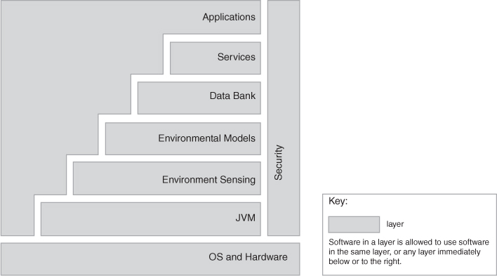
Figure 13.2. A simple layer diagram, with a simple key answering the uses question
But I’m still surprised at how few architects actually bother to do this. And if they don’t, their layer diagrams are ambiguous.
Second, any old set of boxes stacked on top of each other does not constitute a layered architecture. For instance, look at the design shown in Figure 13.3, which uses arrows instead of adjacency to indicate the relationships among the boxes. Here, everything is allowed to use everything. This is decidedly not a layered architecture. The reason is that if Layer A is replaced by a different version, Layer C (which uses it in this figure) might well have to change. We don’t want our virtual machine layer to change every time our application layer changes. But I’m still surprised at how many people call a stack of boxes lined up with each other “layers” (or think that layers are the same as tiers in a multi-tier architecture).
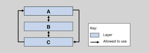
Figure 13.3. A wolf in layer’s clothing
Third, many architectures that purport to be layered look something like Figure 13.4. This diagram probably means that modules in A, B, or C can use modules in D, but without a key to tell us for sure, it could mean anything. “Sidecars” like this often contain common utilities (sometimes imported), such as error handlers, communication protocols, or database access mechanisms. This kind of diagram makes sense only in the case where no layer bridging is allowed in the main stack. Otherwise, D could simply be made the bottom-most layer in the main stack, and the “sidecar” geometry would be unnecessary. But I’m still surprised at how often I see this layout go unexplained.
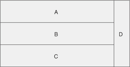
Figure 13.4. Layers with a “sidecar”
Sometimes layers are divided into segments denoting a finer-grained decomposition of the modules. Sometimes this occurs when a preexisting set of units, such as imported modules, share the same allowed-to-use relation. When this happens, you have to specify what usage rules are in effect among the segments. Many usage rules are possible, but they must be made explicit. In Figure 13.5, the top and the bottom layers are segmented. Segments of the top layer are not allowed to use each other, but segments of the bottom layer are. If you draw the same diagram without the arrows, it will be harder to differentiate the different usage rules within segmented layers. Layered diagrams are often a source of hidden ambiguity because the diagram does not make explicit the allowed-to-use relations.
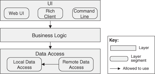
Figure 13.5. Layered design with segmented layers
Finally, the most important point about layering is that a layer isn’t allowed to use any layer above it. A module “uses” another module when it depends on the answer it gets back. But a layer is allowed to make upward calls, as long as it isn’t expecting an answer from them. This is how the common error-handling scheme of callbacks works. A program in layer A calls a program in a lower layer B, and the parameters include a pointer to an error-handling program in A that the lower layer should call in case of error. The software in B makes the call to the program in A, but cares not in the least what it does. By not depending in any way on the contents of A, B is insulated from changes in A.
—PCC
Other Module Patterns
Designers in a particular domain often publish “standard” module decompositions for systems in that domain. These standard decompositions, if put in the “context, problem, solution” form, constitute module decomposition patterns.
Similarly in the object-oriented realm, “standard” or published class/object design solutions for a class of system constitute object-oriented patterns.
Component-and-Connector Patterns
Broker Pattern
Context: Many systems are constructed from a collection of services distributed across multiple servers. Implementing these systems is complex because you need to worry about how the systems will interoperate—how they will connect to each other and how they will exchange information—as well as the availability of the component services.
Problem: How do we structure distributed software so that service users do not need to know the nature and location of service providers, making it easy to dynamically change the bindings between users and providers?
Solution: The broker pattern separates users of services (clients) from providers of services (servers) by inserting an intermediary, called a broker. When a client needs a service, it queries a broker via a service interface. The broker then forwards the client’s service request to a server, which processes the request. The service result is communicated from the server back to the broker, which then returns the result (and any exceptions) back to the requesting client. In this way the client remains completely ignorant of the identity, location, and characteristics of the server. Because of this separation, if a server becomes unavailable, a replacement can be dynamically chosen by the broker. If a server is replaced with a different (compatible) service, again, the broker is the only component that needs to know of this change, and so the client is unaffected. Proxies are commonly introduced as intermediaries in addition to the broker to help with details of the interaction with the broker, such as marshaling and unmarshaling messages.
The down sides of brokers are that they add complexity (brokers and possibly proxies must be designed and implemented, along with messaging protocols) and add a level of indirection between a client and a server, which will add latency to their communication. Debugging brokers can be difficult because they are involved in highly dynamic environments where the conditions leading to a failure may be difficult to replicate. The broker would be an obvious point of attack, from a security perspective, and so it needs to be hardened appropriately. Also a broker, if it is not designed carefully, can be a single point of failure for a large and complex system. And brokers can potentially be bottlenecks for communication.
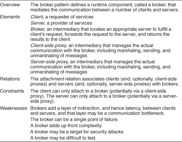
Table 13.2 summarizes the solution of the broker pattern.
Table 13.2. Broker Pattern Solution
The broker is, of course, the critical component in this pattern. The pattern provides all of the modifiability benefits of the use-an-intermediary tactic (described in Chapter 7), an availability benefit (because the broker pattern makes it easy to replace a failed server with another), and a performance benefit (because the broker pattern makes it easy to assign work to the least-busy server). However, the pattern also carries with it some liabilities. For example, the use of a broker precludes performance optimizations that you might make if you knew the precise location and characteristics of the server. Also the use of this pattern adds the overhead of the intermediary and thus latency.
The original version of the broker pattern, as documented by Gamma, Helm, Johnson, and Vlissides [Gamma 94], is given in Figure 13.6.
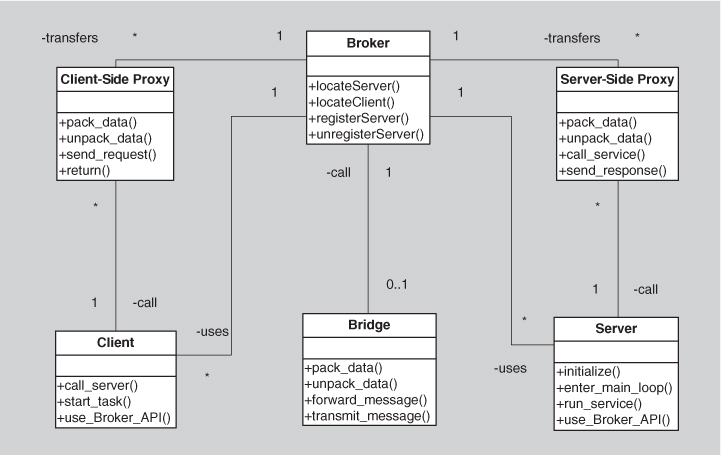
Figure 13.6. The broker pattern
The first widely used implementation of the broker pattern was in the Common Object Request Broker Architecture (CORBA). Other common uses of this pattern are found in Enterprise Java Beans (EJB) and Microsoft’s .NET platform—essentially any modern platform for distributed service providers and consumers implements some form of a broker. The service-oriented architecture (SOA) approach depends crucially on brokers, most commonly in the form of an enterprise service bus.
Model-View-Controller Pattern
Context: User interface software is typically the most frequently modified portion of an interactive application. For this reason it is important to keep modifications to the user interface software separate from the rest of the system. Users often wish to look at data from different perspectives, such as a bar graph or a pie chart. These representations should both reflect the current state of the data.
Problem: How can user interface functionality be kept separate from application functionality and yet still be responsive to user input, or to changes in the underlying application’s data? And how can multiple views of the user interface be created, maintained, and coordinated when the underlying application data changes?
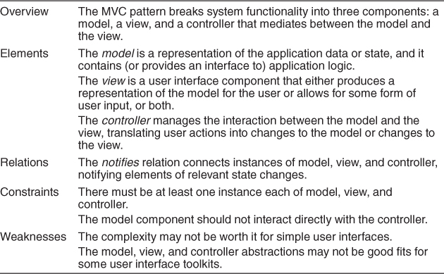
Solution: The model-view-controller (MVC) pattern separates application functionality into three kinds of components:
• A model, which contains the application’s data
• A view, which displays some portion of the underlying data and interacts with the user
• A controller, which mediates between the model and the view and manages the notifications of state changes
MVC is not appropriate for every situation. The design and implementation of three distinct kinds of components, along with their various forms of interaction, may be costly, and this cost may not make sense for relatively simple user interfaces. Also, the match between the abstractions of MVC and commercial user interface toolkits is not perfect. The view and the controller split apart input and output, but these functions are often combined into individual widgets. This may result in a conceptual mismatch between the architecture and the user interface toolkit.
Table 13.3 summarizes the solution of the MVC pattern.
Table 13.3. Model-View-Controller Pattern Solution
There may, in fact, be many views and many controllers associated with a model. For example, a set of business data may be represented as columns of numbers in a spreadsheet, as a scatter plot, or as a pie chart. Each of these is a separate view, and this view can be dynamically updated as the model changes (for example, showing live transactions in a transaction processing system). A model may be updated by different controllers; for example, a map could be zoomed and panned via mouse movements, trackball movements, keyboard clicks, or voice commands; each of these different forms of input needs to be managed by a controller.
The MVC components are connected to each other via some flavor of notification, such as events or callbacks. These notifications contain state updates. A change in the model needs to be communicated to the views so that they may be updated. An external event, such as a user input, needs to be communicated to the controller, which may in turn update the view and/or the model. Notifications may be either push or pull.
Because these components are loosely coupled, it is easy to develop and test them in parallel, and changes to one have minimal impact on the others. The relationships between the components of MVC are shown in Figure 13.7.
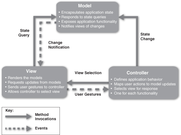
Figure 13.7. The model-view-controller pattern
The MVC pattern is widely used in user interface libraries such as Java’s Swing classes, Microsoft’s ASP.NET framework, Adobe’s Flex software development kit, Nokia’s Qt framework, and many others. As such, it is common for a single application to contain many instances of MVC (often one per user interface object).
Pipe-and-Filter Pattern
Context: Many systems are required to transform streams of discrete data items, from input to output. Many types of transformations occur repeatedly in practice, and so it is desirable to create these as independent, reusable parts.
Problem: Such systems need to be divided into reusable, loosely coupled components with simple, generic interaction mechanisms. In this way they can be flexibly combined with each other. The components, being generic and loosely coupled, are easily reused. The components, being independent, can execute in parallel.
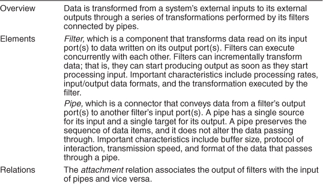
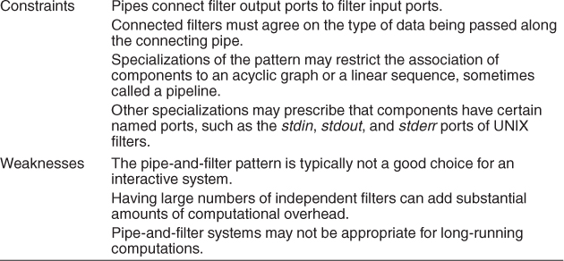
Solution: The pattern of interaction in the pipe-and-filter pattern is characterized by successive transformations of streams of data. Data arrives at a filter’s input port(s), is transformed, and then is passed via its output port(s) through a pipe to the next filter. A single filter can consume data from, or produce data to, one or more ports.
There are several weaknesses associated with the pipe-and-filter pattern. For instance, this pattern is typically not a good choice for an interactive system, as it disallows cycles (which are important for user feedback). Also, having large numbers of independent filters can add substantial amounts of computational overhead, because each filter runs as its own thread or process. Also, pipe-and-filter systems may not be appropriate for long-running computations, without the addition of some form of checkpoint/restore functionality, as the failure of any filter (or pipe) can cause the entire pipeline to fail.
The solution of the pipe-and-filter pattern is summarized in Table 13.4.
Table 13.4. Pipe-and-Filter Pattern Solution
Pipes buffer data during communication. Because of this property, filters can execute asynchronously and concurrently. Moreover, a filter typically does not know the identity of its upstream or downstream filters. For this reason, pipeline pipe-and-filter systems have the property that the overall computation can be treated as the functional composition of the computations of the filters, making it easier for the architect to reason about end-to-end behavior.
Data transformation systems are typically structured as pipes and filters, with each filter responsible for one part of the overall transformation of the input data. The independent processing at each step supports reuse, parallelization, and simplified reasoning about overall behavior. Often such systems constitute the front end of signal-processing applications. These systems receive sensor data at a set of initial filters; each of these filters compresses the data and performs initial processing (such as smoothing). Downstream filters reduce the data further and do synthesis across data derived from different sensors. The final filter typically passes its data to an application, for example providing input to modeling or visualization tools.
Other systems that use pipe-and-filter include those built using UNIX pipes, the request processing architecture of the Apache web server, the map-reduce pattern (presented later in this chapter), Yahoo! Pipes for processing RSS feeds, many workflow engines, and many scientific computation systems that have to process and analyze large streams of captured data. Figure 13.8 shows a UML diagram of a pipe-and-filter system.
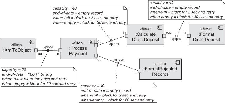
Figure 13.8. A UML diagram of a pipe-and-filter-based system
Client-Server Pattern
Context: There are shared resources and services that large numbers of distributed clients wish to access, and for which we wish to control access or quality of service.
Problem: By managing a set of shared resources and services, we can promote modifiability and reuse, by factoring out common services and having to modify these in a single location, or a small number of locations. We want to improve scalability and availability by centralizing the control of these resources and services, while distributing the resources themselves across multiple physical servers.
Solution: Clients interact by requesting services of servers, which provide a set of services. Some components may act as both clients and servers. There may be one central server or multiple distributed ones.
The client-server pattern solution is summarized in Table 13.5; the component types are clients and servers; the principal connector type for the client-server pattern is a data connector driven by a request/reply protocol used for invoking services.
Table 13.5. Client-Server Pattern Solution
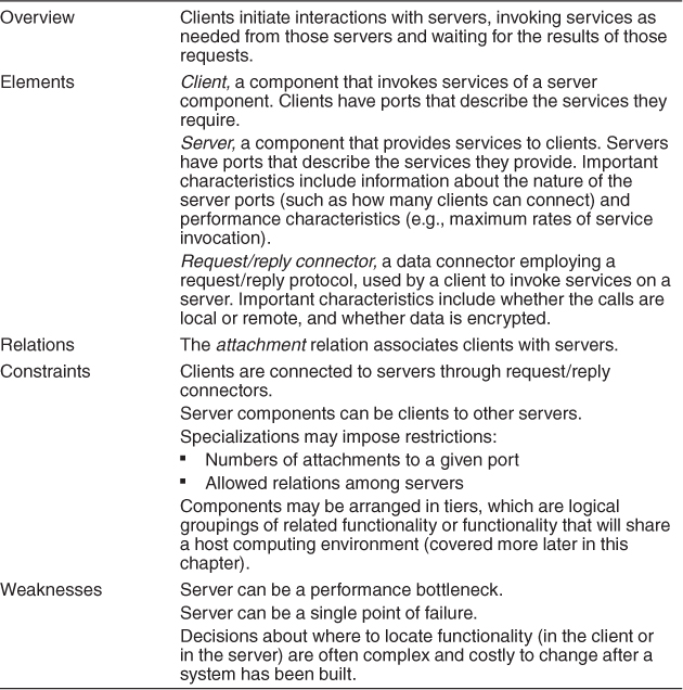
Some of the disadvantages of the client-server pattern are that the server can be a performance bottleneck and it can be a single point of failure. Also, decisions about where to locate functionality (in the client or in the server) are often complex and costly to change after a system has been built.
Some common examples of systems that use the client-server pattern are these:
• Information systems running on local networks where the clients are GUI-launched applications and the server is a database management system
• Web-based applications where the clients are web browsers and the servers are components running on an e-commerce site
The computational flow of pure client-server systems is asymmetric: clients initiate interactions by invoking services of servers. Thus, the client must know the identity of a service to invoke it, and clients initiate all interactions. In contrast, servers do not know the identity of clients in advance of a service request and must respond to the initiated client requests.
In early forms of client-server, service invocation is synchronous: the requester of a service waits, or is blocked, until a requested service completes its actions, possibly providing a return result. However, variants of the client-server pattern may employ more-sophisticated connector protocols. For example:
• Web browsers don’t block until the data request is served up.
• In some client-server patterns, servers are permitted to initiate certain actions on their clients. This might be done by allowing a client to register notification procedures, or callbacks, that the server calls at specific times.
• In other systems service calls over a request/reply connector are bracketed by a “session” that delineates the start and end of a set of a client-server interaction.
The client-server pattern separates client applications from the services they use. This pattern simplifies systems by factoring out common services, which are reusable. Because servers can be accessed by any number of clients, it is easy to add new clients to a system. Similarly, servers may be replicated to support scalability or availability.
The World Wide Web is the best-known example of a system that is based on the client-server pattern, allowing clients (web browsers) to access information from servers across the Internet using HyperText Transfer Protocol (HTTP). HTTP is a request/reply protocol. HTTP is stateless; the connection between the client and the server is terminated after each response from the server.
Figure 13.9 uses an informal notation to describe the client-server view of an automatic teller machine (ATM) banking system.
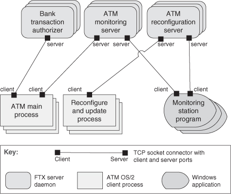
Figure 13.9. The client-server architecture of an ATM banking system
Peer-to-Peer Pattern
Context: Distributed computational entities—each of which is considered equally important in terms of initiating an interaction and each of which provides its own resources—need to cooperate and collaborate to provide a service to a distributed community of users.
Problem: How can a set of “equal” distributed computational entities be connected to each other via a common protocol so that they can organize and share their services with high availability and scalability?
Solution: In the peer-to-peer (P2P) pattern, components directly interact as peers. All peers are “equal” and no peer or group of peers can be critical for the health of the system. Peer-to-peer communication is typically a request/reply interaction without the asymmetry found in the client-server pattern. That is, any component can, in principle, interact with any other component by requesting its services. The interaction may be initiated by either party—that is, in client-server terms, each peer component is both a client and a server. Sometimes the interaction is just to forward data without the need for a reply. Each peer provides and consumes similar services and uses the same protocol. Connectors in peer-to-peer systems involve bidirectional interactions, reflecting the two-way communication that may exist between two or more peer-to-peer components.
Peers first connect to the peer-to-peer network on which they discover other peers they can interact with, and then initiate actions to achieve their computation by cooperating with other peers by requesting services. Often a peer’s search for another peer is propagated from one peer to its connected peers for a limited number of hops. A peer-to-peer architecture may have specialized peer nodes (called supernodes) that have indexing or routing capabilities and allow a regular peer’s search to reach a larger number of peers.
Peers can be added and removed from the peer-to-peer network with no significant impact, resulting in great scalability for the whole system. This provides flexibility for deploying the system across a highly distributed platform.
Typically multiple peers have overlapping capabilities, such as providing access to the same data or providing equivalent services. Thus, a peer acting as client can collaborate with multiple peers acting as servers to complete a certain task. If one of these multiple peers becomes unavailable, the others can still provide the services to complete the task. The result is improved overall availability. There are also performance advantages: The load on any given peer component acting as a server is reduced, and the responsibilities that might have required more server capacity and infrastructure to support it are distributed. This can decrease the need for other communication for updating data and for central server storage, but at the expense of storing the data locally.
The drawbacks of the peer-to-peer pattern are strongly related to its strengths. Because peer-to-peer systems are decentralized, managing security, data consistency, data and service availability, backup, and recovery are all more complex. In many cases it is difficult to provide guarantees with peer-to-peer systems because the peers come and go; instead, the architect can, at best, offer probabilities that quality goals will be met, and these probabilities typically increase with the size of the population of peers.
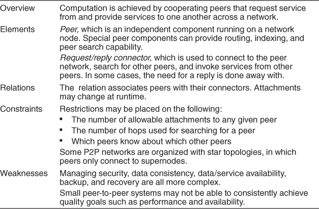
Table 13.6 on the next page summarizes the peer-to-peer pattern solution.
Table 13.6. Peer-to-Peer Pattern Solution
Peer-to-peer computing is often used in distributed computing applications such as file sharing, instant messaging, desktop grid computing, routing, and wireless ad hoc networking. Examples of peer-to-peer systems include file-sharing networks such as BitTorrent and eDonkey, and instant messaging and VoIP applications such as Skype. Figure 13.10 shows an example of an instantiation of the peer-to-peer pattern.
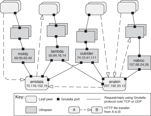
Figure 13.10. A peer-to-peer view of a Gnutella network using an informal C&C notation. For brevity, only a few peers are identified. Each of the identified leaf peers uploads and downloads files directly from other peers.
Service-Oriented Architecture Pattern
Context: A number of services are offered (and described) by service providers and consumed by service consumers. Service consumers need to be able to understand and use these services without any detailed knowledge of their implementation.
Problem: How can we support interoperability of distributed components running on different platforms and written in different implementation languages, provided by different organizations, and distributed across the Internet? How can we locate services and combine (and dynamically recombine) them into meaningful coalitions while achieving reasonable performance, security, and availability?
Solution: The service-oriented architecture (SOA) pattern describes a collection of distributed components that provide and/or consume services. In an SOA, service provider components and service consumer components can use different implementation languages and platforms. Services are largely standalone: service providers and service consumers are usually deployed independently, and often belong to different systems or even different organizations. Components have interfaces that describe the services they request from other components and the services they provide. A service’s quality attributes can be specified and guaranteed with a service-level agreement (SLA). In some cases, these are legally binding. Components achieve their computation by requesting services from one another.
The elements in this pattern include service providers and service consumers, which in practice can take different forms, from JavaScript running on a web browser to CICS transactions running on a mainframe. In addition to the service provider and service consumer components, an SOA application may use specialized components that act as intermediaries and provide infrastructure services:
• Service invocation can be mediated by an enterprise service bus (ESB). An ESB routes messages between service consumers and service providers. In addition, an ESB can convert messages from one protocol or technology to another, perform various data transformations (e.g., format, content, splitting, merging), perform security checks, and manage transactions. Using an ESB promotes interoperability, security, and modifiability. Of course, communicating through an ESB adds overhead thereby lowering performance, and introduces an additional point of failure. When an ESB is not in place, service providers and consumers communicate with each other in a point-to-point fashion.
• To improve the independence of service providers, a service registry can be used in SOA architectures. The registry is a component that allows services to be registered at runtime. This enables runtime discovery of services, which increases system modifiability by hiding the location and identity of the service provider. A registry can even permit multiple live versions of the same service.
• An orchestration server (or orchestration engine) orchestrates the interaction among various service consumers and providers in an SOA system. It executes scripts upon the occurrence of a specific event (e.g., a purchase order request arrived). Applications with well-defined business processes or workflows that involve interactions with distributed components or systems gain in modifiability, interoperability, and reliability by using an orchestration server. Many commercially available orchestration servers support various workflow or business process language standards.
The basic types of connectors used in SOA are these:
• SOAP. The standard protocol for communication in the web services technology. Service consumers and providers interact by exchanging request/reply XML messages typically on top of HTTP.
• Representational State Transfer (REST). A service consumer sends nonblocking HTTP requests. These requests rely on the four basic HTTP commands (POST, GET, PUT, DELETE) to tell the service provider to create, retrieve, update, or delete a resource.
• Asynchronous messaging, a “fire-and-forget” information exchange. Participants do not have to wait for an acknowledgment of receipt, because the infrastructure is assumed to have delivered the message successfully. The messaging connector can be point-to-point or publish-subscribe.
In practice, SOA environments may involve a mix of the three connectors just listed, along with legacy protocols and other communication alternatives (e.g., SMTP). Commercial products such as IBM’s WebSphere MQ, Microsoft’s MSMQ, or Apache’s ActiveMQ are infrastructure components that provide asynchronous messaging. SOAP and REST are described in more detail in Chapter 6.
As you can see, the SOA pattern can be quite complex to design and implement (due to dynamic binding and the concomitant use of metadata). Other potential problems with this pattern include the performance overhead of the middleware that is interposed between services and clients and the lack of performance guarantees (because services are shared and, in general, not under control of the requester). These weaknesses are all shared with the broker pattern, which is not surprising because the SOA pattern shares many of the design concepts and goals of broker. In addition, because you do not, in general, control the evolution of the services that you use, you may have to endure high and unplanned-for maintenance costs.
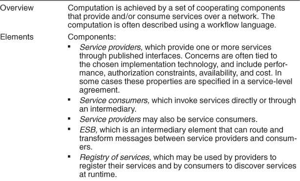
Table 13.7 summarizes the SOA pattern.
Table 13.7. Service-Oriented Architecture Pattern Solution
The main benefit and the major driver of SOA is interoperability. Because service providers and service consumers may run on different platforms, service-oriented architectures often integrate a variety of systems, including legacy systems. SOA also offers the necessary elements to interact with external services available over the Internet. Special SOA components such as the registry or the ESB also allow dynamic reconfiguration, which is useful when there’s a need to replace or add versions of components with no system interruption.
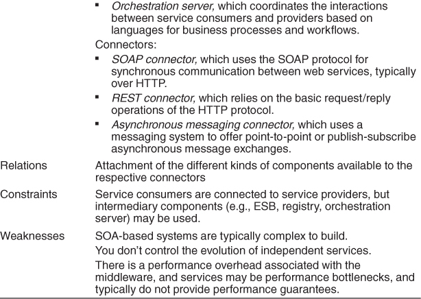
Figure 13.11 shows the SOA view of a system called Adventure Builder. Adventure Builder allows a customer on the web to assemble a vacation by choosing an activity and lodging at and transportation to a destination. The Adventure Builder system interacts with external service providers to construct the vacation, and with bank services to process payment. The central OPC (Order Processing Center) component coordinates the interaction with internal and external service consumers and providers. Note that the external providers can be legacy mainframe systems, Java systems, .NET systems, and so on. The nature of these external components is transparent because SOAP provides the necessary interoperability.
Figure 13.11. Diagram of the SOA view for the Adventure Builder system. OPC stands for “Order Processing Center.”
Publish-Subscribe Pattern
Context: There are a number of independent producers and consumers of data that must interact. The precise number and nature of the data producers and consumers are not predetermined or fixed, nor is the data that they share.
Problem: How can we create integration mechanisms that support the ability to transmit messages among the producers and consumers in such a way that they are unaware of each other’s identity, or potentially even their existence?
Solution: In the publish-subscribe pattern, summarized in Table 13.8, components interact via announced messages, or events. Components may subscribe to a set of events. It is the job of the publish-subscribe runtime infrastructure to make sure that each published event is delivered to all subscribers of that event. Thus, the main form of connector in these patterns is an event bus. Publisher components place events on the bus by announcing them; the connector then delivers those events to the subscriber components that have registered an interest in those events. Any component may be both a publisher and a subscriber.
Table 13.8. Publish-Subscribe Pattern Solution
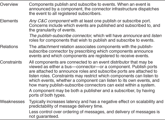
Publish-subscribe adds a layer of indirection between senders and receivers. This has a negative effect on latency and potentially scalability, depending on how it is implemented. One would typically not want to use publish-subscribe in a system that had hard real-time deadlines to meet, as it introduces uncertainty in message delivery times.
Also, the publish-subscribe pattern suffers in that it provides less control over ordering of messages, and delivery of messages is not guaranteed (because the sender cannot know if a receiver is listening). This can make the publish-subscribe pattern inappropriate for complex interactions where shared state is critical.
There are some specific refinements of this pattern that are in common use. We will describe several of these later in this section.
The computational model for the publish-subscribe pattern is best thought of as a system of independent processes or objects, which react to events generated by their environment, and which in turn cause reactions in other components as a side effect of their event announcements. An example of the publish-subscribe pattern, implemented on top of the Eclipse platform, is shown in Figure 13.12.
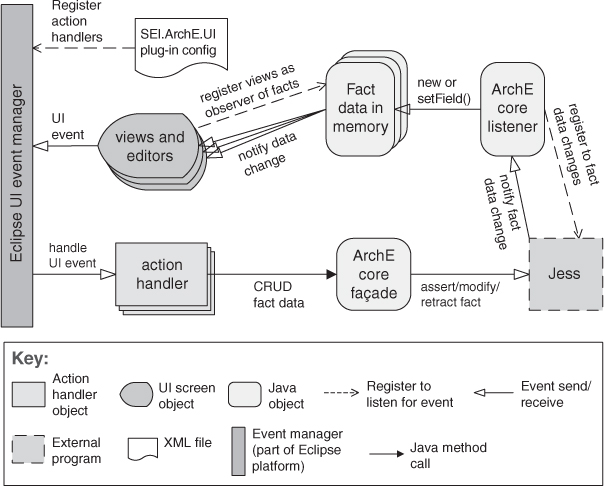
Figure 13.12. A typical publish-subscribe pattern realization
Typical examples of systems that employ the publish-subscribe pattern are the following:
• Graphical user interfaces, in which a user’s low-level input actions are treated as events that are routed to appropriate input handlers
• MVC-based applications, in which view components are notified when the state of a model object changes
• Enterprise resource planning (ERP) systems, which integrate many components, each of which is only interested in a subset of system events
• Extensible programming environments, in which tools are coordinated through events
• Mailing lists, where a set of subscribers can register interest in specific topics
• Social networks, where “friends” are notified when changes occur to a person’s website
The publish-subscribe pattern is used to send events and messages to an unknown set of recipients. Because the set of event recipients is unknown to the event producer, the correctness of the producer cannot, in general, depend on those recipients. Thus, new recipients can be added without modification to the producers.
Having components be ignorant of each other’s identity results in easy modification of the system (adding or removing producers and consumers of data) but at the cost of runtime performance, because the publish-subscribe infrastructure is a kind of indirection, which adds latency. In addition, if the publish-subscribe connector fails completely, this is a single point of failure for the entire system.
The publish-subscribe pattern can take several forms:
• List-based publish-subscribe is a realization of the pattern where every publisher maintains a subscription list—a list of subscribers that have registered an interest in receiving the event. This version of the pattern is less decoupled than others, as we shall see below, and hence it does not provide as much modifiability, but it can be quite efficient in terms of runtime overhead. Also, if the components are distributed, there is no single point of failure.
• Broadcast-based publish-subscribe differs from list-based publish-subscribe in that publishers have less (or no) knowledge of the subscribers. Publishers simply publish events, which are then broadcast. Subscribers (or in a distributed system, services that act on behalf of the subscribers) examine each event as it arrives and determine whether the published event is of interest. This version has the potential to be very inefficient if there are lots of messages and most messages are not of interest to a particular subscriber.
• Content-based publish-subscribe is distinguished from the previous two variants, which are broadly categorized as “topic-based.” Topics are predefined events, or messages, and a component subscribes to all events within the topic. Content, on the other hand, is much more general. Each event is associated with a set of attributes and is delivered to a subscriber only if those attributes match subscriber-defined patterns.
In practice the publish-subscribe pattern is typically realized by some form of message-oriented middleware, where the middleware is realized as a broker, managing the connections and channels of information between producers and consumers. This middleware is often responsible for the transformation of messages (or message protocols), in addition to routing and sometimes storing the messages. Thus the publish-subscribe pattern inherits the strengths and weaknesses of the broker pattern.
Shared-Data Pattern
Context: Various computational components need to share and manipulate large amounts of data. This data does not belong solely to any one of those components.
Problem: How can systems store and manipulate persistent data that is accessed by multiple independent components?
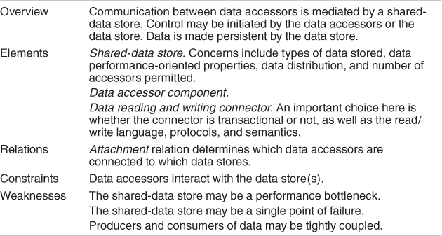
Solution: In the shared-data pattern, interaction is dominated by the exchange of persistent data between multiple data accessors and at least one shared-data store. Exchange may be initiated by the accessors or the data store. The connector type is data reading and writing. The general computational model associated with shared-data systems is that data accessors perform operations that require data from the data store and write results to one or more data stores. That data can be viewed and acted on by other data accessors. In a pure shared-data system, data accessors interact only through one or more shared-data stores. However, in practice shared-data systems also allow direct interactions between data accessors. The data-store components of a shared-data system provide shared access to data, support data persistence, manage concurrent access to data through transaction management, provide fault tolerance, support access control, and handle the distribution and caching of data values.
Specializations of the shared-data pattern differ with respect to the nature of the stored data—existing approaches include relational, object structures, layered, and hierarchical structures.
Although the sharing of data is a critical task for most large, complex systems, there are a number of potential problems associated with this pattern. For one, the shared-data store may be a performance bottleneck. For this reason, performance optimization has been a common theme in database research. The shared-data store is also potentially a single point of failure. Also, the producers and consumers of the shared data may be tightly coupled, through their knowledge of the structure of the shared data.
The shared-data pattern solution is summarized in Table 13.9.
Table 13.9. Shared-Data Pattern Solution
The shared-data pattern is useful whenever various data items are persistent and have multiple accessors. Use of this pattern has the effect of decoupling the producer of the data from the consumers of the data; hence, this pattern supports modifiability, as the producers do not have direct knowledge of the consumers. Consolidating the data in one or more locations and accessing it in a common fashion facilitates performance tuning. Analyses associated with this pattern usually center on qualities such as data consistency, performance, security, privacy, availability, scalability, and compatibility with, for example, existing repositories and their data.
When a system has more than one data store, a key architecture concern is the mapping of data and computation to the data. Use of multiple stores may occur because the data is naturally, or historically, partitioned into separable stores. In other cases data may be replicated over several stores to improve performance or availability through redundancy. Such choices can strongly affect the qualities noted above.
Figure 13.13 shows the diagram of a shared-data view of an enterprise access management system. There are three types of accessor components: Windows applications, web applications, and headless programs (programs or scripts that run in background and don’t provide any user interface).
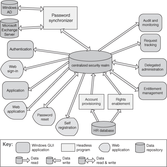
Figure 13.13. The shared-data diagram of an enterprise access management system
Allocation Patterns
Map-Reduce Pattern
Context: Businesses have a pressing need to quickly analyze enormous volumes of data they generate or access, at petabyte scale. Examples include logs of interactions in a social network site, massive document or data repositories, and pairs of <source, target> web links for a search engine. Programs for the analysis of this data should be easy to write, run efficiently, and be resilient with respect to hardware failure.
Problem: For many applications with ultra-large data sets, sorting the data and then analyzing the grouped data is sufficient. The problem the map-reduce pattern solves is to efficiently perform a distributed and parallel sort of a large data set and provide a simple means for the programmer to specify the analysis to be done.
Solution: The map-reduce pattern requires three parts: First, a specialized infrastructure takes care of allocating software to the hardware nodes in a massively parallel computing environment and handles sorting the data as needed. A node may be a standalone processor or a core in a multi-core chip. Second and third are two programmer-coded functions called, predictably enough, map and reduce.
The map function takes as input a key (key1) and a data set. The purpose of the map function is to filter and sort the data set. All of the heavy analysis takes place in the reduce function. The input key in the map function is used to filter the data. Whether a data record is to be involved in further processing is determined by the map function. A second key (key2) is also important in the map function. This is the key that is used for sorting. The output of the map function consists of a <key2, value> pair, where the key2 is the sorting value and the value is derived from the input record.
Sorting is performed by a combination of the map and the infrastructure. Each record output by map is hashed by key2 into a disk partition. The infrastructure maintains an index file for key2 on the disk partition. This allows for the values on the disk partition to be retrieved in key2 order.
The performance of the map phase of map-reduce is enhanced by having multiple map instances, each processing a different portion of the disk file being processed. Figure 13.14 shows how the map portion of map-reduce processes data. An input file is divided into portions, and a number of map instances are created to process each portion. The map function processes its portion into a number of partitions, based on programmer-specified logic.
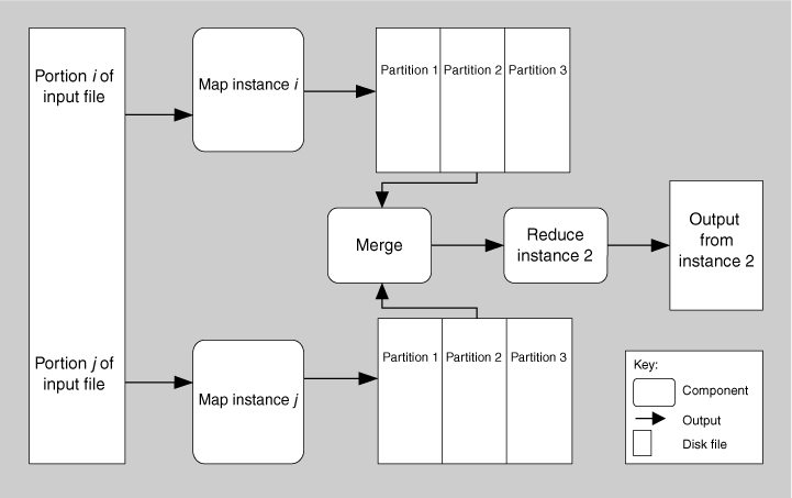
Figure 13.14. A component-and-connector view of map-reduce showing how the data processed by map is partitioned and subsequently processed by reduce
The reduce function is provided with all the sets of <key2, value> pairs emitted by all the map instances in sorted order. Reduce does some programmer-specified analysis and then emits the results of that analysis. The output set is almost always much smaller than the input sets, hence the name “reduce.” The term “load” is sometimes used to describe the final set of data emitted. Figure 13.14 also shows one instance (of many possible instances) of the reduce processing, called Reduce Instance 2. Reduce Instance 2 is receiving data from all of the Partition 2s produced by the various map instances. It is possible that there are several iterations of reduce for large files, but this is not shown in Figure 13.14.
A classic teaching problem for map-reduce is counting word occurrences in a document. This example can be carried out with a single map function. The document is the data set. The map function will find every word in the document and output a <word, 1> pair for each. For example, if the document begins with the words “Having a whole book ...,” then the first results of map will be
<Having, 1>
<a, 1>
<whole, 1>
<book, 1>
In practice, the “a” would be one of the words filtered by map.
Pseudocode for map might look like this:
map(String key, String value):
// key: document name
// value: document contents
for each word w in value:
Emit (w, "1");
The reduce function will take that list in sorted order, add up the 1s for each word to get a count, and output the result.
The corresponding reduce function would look like this:
reduce(List <key, value>):
// key: a word
// value: an integer
int result = 0;
sort input
for each input value:
for each input pair with same word
result ++ ;
Emit (word, result)
result = 0
Larger data sets lead to a much more interesting solution. Suppose we want to continuously analyze Twitter posts over the last hour to see what topics are currently “trending.” This is analogous to counting word occurrences in millions of documents. In that case, each document (tweet) can be assigned to its own instance of the map function. (If you don’t have millions of processors handy, you can break the tweet collection into groups that match the number of processors in your processor farm, and process the collection in waves, one group after the other.) Or we can use a dictionary to give us a list of words, and each map function can be assigned its own word to look for across all tweets.
There can also be multiple instances of reduce. These are usually arranged so that the reduction happens in stages, with each stage processing a smaller list (with a smaller number of reduce instances) than the previous stage. The final stage is handled by a single reduce function that produces the final output.
Of course, the map-reduce pattern is not appropriate in all instances. Some considerations that would argue against adopting this pattern are these:
• If you do not have large data sets, then the overhead of map-reduce is not justified.
• If you cannot divide your data set into similar sized subsets, the advantages of parallelism are lost.
• If you have operations that require multiple reduces, this will be complex to orchestrate.
Commercial implementations of map-reduce provide infrastructure that takes care of assignment of function instances to hardware, recovery and reassignment in case of hardware failure (a common occurrence in massively parallel computing environments), and utilities like sorting of the massive lists that are produced along the way.
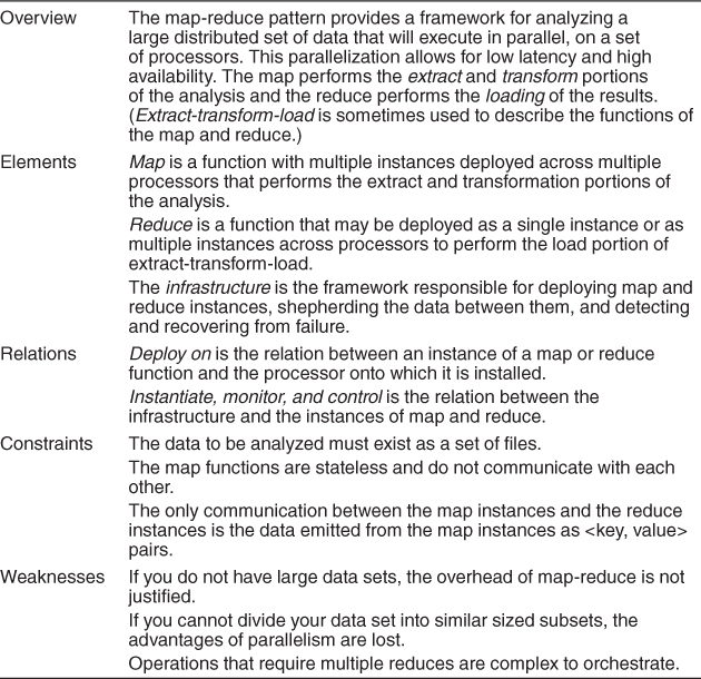
Table 13.10 summarizes the solution of the map-reduce pattern.
Table 13.10. Map-Reduce Pattern Solution
Map-reduce is a cornerstone of the software of some of the most familiar names on the web, including Google, Facebook, eBay, and Yahoo!
Multi-tier Pattern
The multi-tier pattern is a C&C pattern or an allocation pattern, depending on the criteria used to define the tiers. Tiers can be created to group components of similar functionality, in which case it is a C&C pattern. However, in many, if not most, cases tiers are defined with an eye toward the computing environment on which the software will run: A client tier in an enterprise system will not be running on the computer that hosts the database. That makes it an allocation pattern, mapping software elements—perhaps produced by applying C&C patterns—to computing elements. Because of that reason, we have chosen to list it as an allocation pattern.
Context: In a distributed deployment, there is often a need to distribute a system’s infrastructure into distinct subsets. This may be for operational or business reasons (for example, different parts of the infrastructure may belong to different organizations).
Problem: How can we split the system into a number of computationally independent execution structures—groups of software and hardware—connected by some communications media? This is done to provide specific server environments optimized for operational requirements and resource usage.
Solution: The execution structures of many systems are organized as a set of logical groupings of components. Each grouping is termed a tier. The grouping of components into tiers may be based on a variety of criteria, such as the type of component, sharing the same execution environment, or having the same runtime purpose.
The use of tiers may be applied to any collection (or pattern) of runtime components, although in practice it is most often used in the context of client-server patterns. Tiers induce topological constraints that restrict which components may communicate with other components. Specifically, connectors may exist only between components in the same tier or residing in adjacent tiers. The multi-tier pattern found in many Java EE and Microsoft .NET applications is an example of organization in tiers derived from the client-server pattern.
Additionally, tiers may constrain the kinds of communication that can take place across adjacent tiers. For example, some tiered patterns require call-return communication in one direction but event-based notification in the other.
The main weakness with the multi-tier architecture is its cost and complexity. For simple systems, the benefits of the multi-tier architecture may not justify its up-front and ongoing costs, in terms of hardware, software, and design and implementation complexity.
Tiers are not components, but rather logical groupings of components. Also, don’t confuse tiers with layers! Layering is a pattern of modules (a unit of implementation), while tiers applies only to runtime entities.
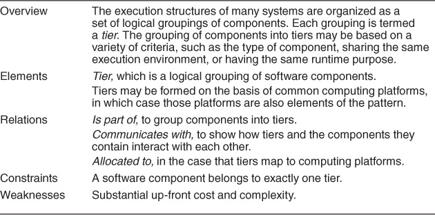
Table 13.11 summarizes the solution part of the multi-tier pattern.
Table 13.11. Multi-tier Pattern Solution
Tiers make it easier to ensure security, and to optimize performance and availability in specialized ways. They also enhance the modifiability of the system, as the computationally independent subgroups need to agree on protocols for interaction, thus reducing their coupling.
Figure 13.15 uses an informal notation to describe the multi-tier architecture of the Consumer Website Java EE application. This application is part of the Adventure Builder system. Many component-and-connector types are specific to the supporting platform, which is Java EE in this case.
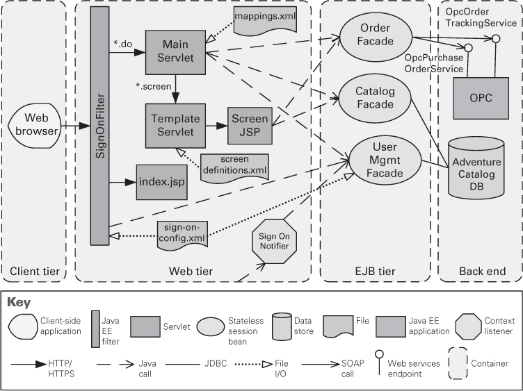
Figure 13.15. A multi-tier view of the Consumer Website Java EE application, which is part of the Adventure Builder system
Other Allocation Patterns
There are several published deployment styles. Microsoft publishes a “Tiered Distribution” pattern, which prescribes a particular allocation of components in a multi-tier architecture to the hardware they will run on. Similarly, IBM’s WebSphere handbooks describe a number of what they call “topologies” along with the quality attribute criteria for choosing among them. There are 11 topologies (specialized deployment patterns) described for WebSphere version 6, including the “single machine topology (stand-alone server),” “reverse proxy topology,” “vertical scaling topology,” “horizontal scaling topology,” and “horizontal scaling with IP sprayer topology.”
There are also published work assignment patterns. These take the form of often-used team structures. For example, patterns for globally distributed Agile projects include these:
• Platform. In software product line development, one site is tasked with developing reusable core assets of the product line, and other sites develop applications that use the core assets.
• Competence center. Work is allocated to sites depending on the technical or domain expertise located at a site. For example, user interface design is done at a site where usability engineering experts are located.
• Open source. Many independent contributors develop the software product in accordance with a technical integration strategy. Centralized control is minimal, except when an independent contributor integrates his code into the product line.
13.3. Relationships between Tactics and Patterns
Patterns and tactics together constitute the software architect’s primary tools of the trade. How do they relate to each other?
Patterns Comprise Tactics
As we said in the introduction to this chapter, tactics are the “building blocks” of design from which architectural patterns are created. Tactics are atoms and patterns are molecules. Most patterns consist of (are constructed from) several different tactics, and although these tactics might all serve a common purpose—such as promoting modifiability, for example—they are often chosen to promote different quality attributes. For example, a tactic might be chosen that makes an availability pattern more secure, or that mitigates the performance impact of a modifiability pattern.
Consider the example of the layered pattern, the most common pattern in all of software architecture (virtually all nontrivial systems employ layering). The layered pattern can be seen as the amalgam of several tactics—increase semantic coherence, abstract common services, encapsulate, restrict communication paths, and use an intermediary. For example:
• Increase semantic coherence. The goal of ensuring that a layer’s responsibilities all work together without excessive reliance on other layers is achieved by choosing responsibilities that have semantic coherence. Doing so binds responsibilities that are likely to be affected by a change. For example, responsibilities that deal with hardware should be allocated to a hardware layer and not to an application layer; a hardware responsibility typically does not have semantic coherence with the application responsibilities.
• Restrict dependencies. Layers define an ordering and only allow a layer to use the services of its adjacent lower layer. The possible communication paths are reduced to the number of layers minus one. This limitation has a great influence on the dependencies between the layers and makes it much easier to limit the side effects of replacing a layer.
Without any one of its tactics, the pattern might be ineffective. For example, if the restrict dependencies tactic is not employed, then any function in any layer can call any other function in any other layer, destroying the low coupling that makes the layering pattern effective. If the increase semantic coherence tactic is not employed, then functionality could be randomly sprinkled throughout the layers, destroying the separation of concerns, and hence ease of modification, which is the prime motivation for employing layers in the first place.
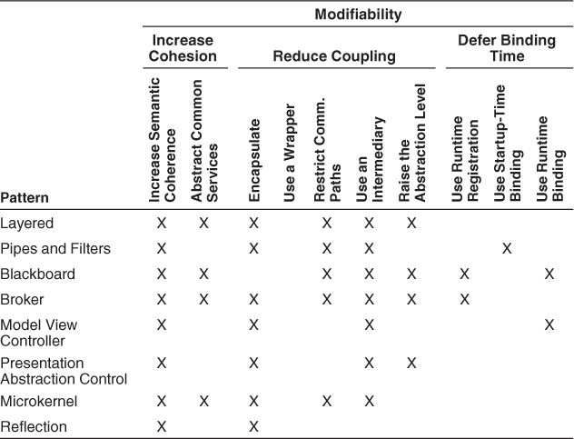
Table 13.12 shows a number of the architectural patterns described in the book Pattern-Oriented Software Architecture Volume 1: A System of Patterns, by Buschmann et al., and shows which modifiability tactics they employ.
Table 13.12. Architecture Patterns and Corresponding Tactics ([Bachmann 07])
Using Tactics to Augment Patterns
A pattern is described as a solution to a class of problems in a general context. When a pattern is chosen and applied, the context of its application becomes very specific. A documented pattern is therefore underspecified with respect to applying it in a specific situation.
To make a pattern work in a given architectural context, we need to examine it from two perspectives:
• The inherent quality attribute tradeoffs that the pattern makes. Patterns exist to achieve certain quality attributes, and we need to compare the ones they promote (and the ones they diminish) with our needs.
• Other quality attributes that the pattern isn’t directly concerned with, but which it nevertheless affects, and which are important in our application.
To illustrate these concerns in particular, and how to use tactics to augment patterns in general, we’ll use the broker pattern as a starting point.
The broker pattern is widely used in distributed systems and dates back at least to its critical role in CORBA-based systems. Broker is a crucial component of any large-scale, dynamic, service-oriented architecture.
Using this pattern, a client requesting some information from a server does not need to know the location or APIs of the server. The client simply contacts the broker (typically through a client-side proxy); this is illustrated in the UML sequence diagram in Figure 13.16.
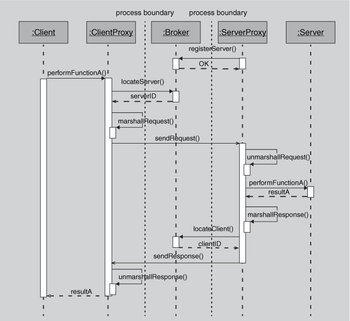
Figure 13.16. A sequence diagram showing a typical client-server interaction mediated by a broker
Weaknesses of the Broker Pattern
In Section 13.2 we enumerated several weaknesses of the broker pattern. Here we will examine these weaknesses in more detail. The broker pattern has several weaknesses with respect to certain quality attributes. For example:
• Availability. The broker, if implemented as suggested in Figure 13.6, is a single point of failure. The liveness of servers, the broker, and perhaps even the clients need to be monitored, and repair mechanisms must be provided.
• Performance. The levels of indirection between the client (requesting the information or service) and the server (providing the information or service) add overhead, and hence add latency. Also, the broker is a potential performance bottleneck if direct communication between the client and server is not desired (for example, for security reasons).
• Testability. Brokers are employed in complex multi-process and multi-processor systems. Such systems are typically highly dynamic. Requests and responses are typically asynchronous. All of this makes testing and debugging such systems extremely difficult. But the description of the broker pattern provides no testing functionality, such as testing interfaces, state or activity capture and playback capabilities, and so forth.
• Security. Because the broker pattern is primarily used when the system spans process and processor boundaries—such as on web-based systems—security is a legitimate concern. However, the broker pattern as presented does not offer any means to authenticate or authorize clients or servers, and provides no means of protecting the communication between clients and servers.
Of these quality attributes, the broker pattern is mainly associated with poor performance (the well-documented price for the loose coupling it brings to systems). It is largely unconcerned with the other quality attributes in this list; they aren’t mentioned in most published descriptions. But as the other bullets show, they can be unacceptable “collateral damage” that come with the broker’s benefits.
Improving the Broker Pattern with Tactics
How can we use tactics to plug the gaps between the “out of the box” broker pattern and a version of it that will let us meet the requirements of a demanding distributed system? Here are some options:
• The increase available resources performance tactic would lead to multiple brokers, to help with performance and availability.
• The maintain multiple copies tactic would allow each of these brokers to share state, to ensure that they respond identically to client requests.
• Load balancing (an application of the scheduling resources tactic) would ensure that one broker is not overloaded while another one sits idle.
• Heartbeat, exception detection, or ping/echo would give the replicated brokers a way of notifying clients and notifying each other when one of them is out of service, as a means of detecting faults.
Of course, each of these tactics brings a tradeoff. Each complicates the design, which will now take longer to implement, be more costly to acquire, and be more costly to maintain. Load balancing introduces indirection that will add latency to each transaction, thus giving back some of the performance it was intended to increase. And the load balancer is a single point of failure, so it too must be replicated, further increasing the design cost and complexity.
13.4. Using Tactics Together
Tactics, as described in Chapters 5–11, are design primitives aimed at managing a single quality attribute response. Of course, this is almost never true in practice; every tactic has its main effect—to manage modifiability or performance or safety, and so on—and it has its side effects, its tradeoffs. On the face of it, the situation for an architect sounds hopeless. Whatever you do to improve one quality attribute endangers another. We are able to use tactics profitably because we can gauge the direct and side effects of a tactic, and when the tradeoff is acceptable, we employ the tactic. In doing so we gain some benefit in our quality attribute of interest while giving up something else (with respect to a different quality attribute and, we hope, of a much smaller magnitude).
This section will walk through an example that shows how applying tactics to a pattern can produce negative effects in one area, but how adding other tactics can bring relief and put you back in an acceptable design space. The point is to show the interplay between tactics that you can use to your advantage. Just as some combinations of liquids are noxious whereas others yield lovely things like strawberry lemonade, tactics can either make things worse or put you in a happy design space. Here, then, is a walkthrough of tactic mixology.
Consider a system that needs to detect faults in its components. A common tactic for detecting faults is ping/echo. Let us assume that the architect has decided to employ ping/echo as a way to detect failed components in the system. Every tactic has one or more side effects, and ping/echo is no different. Common considerations associated with ping/echo are these:
• Security. How to prevent a ping flood attack?
• Performance. How to ensure that the performance overhead of ping/echo is small?
• Modifiability. How to add ping/echo to the existing architecture?
We can represent the architect’s reasoning and decisions thus far as shown in Figure 13.17.
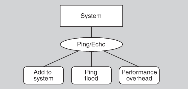
Figure 13.17. Partial availability decisions
Suppose the architect determines that the performance tradeoff (the overhead of adding ping/echo to the system) is the most severe. A tactic to address the performance side effect is increase available resources. Considerations associated with increase available resources are these:
• Cost. Increased resources cost more.
• Performance. How to utilize the increased resources efficiently?
This set of design decisions can now be represented as shown in Figure 13.18.
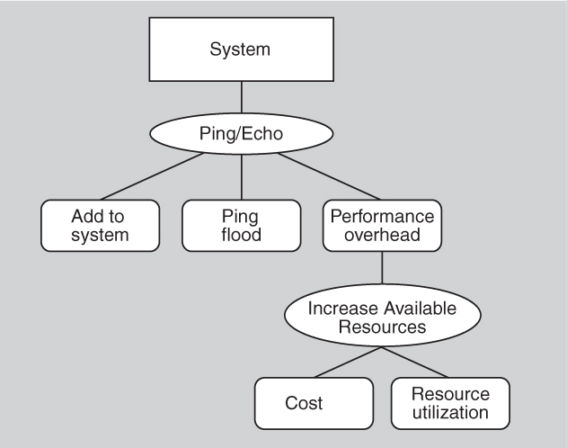
Figure 13.18. More availability decisions
Now the architect chooses to deal with the resource utilization consequence of employing increase available resources. These resources must be used efficiently or else they are simply adding cost and complexity to the system. A tactic that can address the efficient use of resources is the employment of a scheduling policy. Considerations associated with the scheduling policy tactic are these:
• Modifiability. How to add the scheduling policy to the existing architecture?
• Modifiability. How to change the scheduling policy in the future?
The set of design decisions that includes the scheduling policy tactic can now be represented as in Figure 13.19.
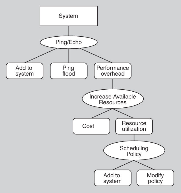
Figure 13.19. Still more availability decisions
Next the architect chooses to deal with the modifiability consequence of employing a scheduling policy tactic. A tactic to address the addition of the scheduler to the system is to use an intermediary, which will insulate the choice of scheduling policy from the rest of the system. One consideration associated with use an intermediary is this:
• Modifiability. How to ensure that all communication passes through the intermediary?
We can now represent the tactics-based set of architectural design decisions made thus far as in Figure 13.20.
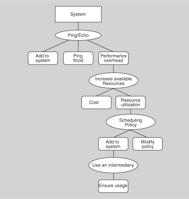
Figure 13.20. As far as we go with availability decisions
A tactic to address the concern that all communication passes through the intermediary is restrict dependencies. One consideration associated with the restrict dependencies tactic is this:
• Performance. How to ensure that the performance overhead of the intermediary is not excessive?
This design problem has now become recursive! At this point (or in fact, at any point in the tree of design decisions that we have described) the architect might determine that the performance overhead of the intermediary is small enough that no further design decisions need to be made.
Applying successive tactics is like moving through a game space, and it’s a little like chess: Good players are able to see the consequences of the move they’re considering, and the very good players are able to look several moves ahead. In Chapter 17 we’ll see the activity of design treated as an exercise of “generate and test”: propose a design and test it to see if it’s satisfactory. Applying tactics to an existing design solution, such as a pattern, is one technique for generating a design for subsequent testing.
13.5. Summary
An architectural pattern
• is a package of design decisions that is found repeatedly in practice,
• has known properties that permit reuse, and
• describes a class of architectures.
Because patterns are (by definition) found repeatedly in practice, one does not invent them; one discovers them.
Tactics are simpler than patterns. Tactics typically use just a single structure or computational mechanism, and they are meant to address a single architectural force. For this reason they give more precise control to an architect when making design decisions than patterns, which typically combine multiple design decisions into a package. Tactics are the “building blocks” of design from which architectural patterns are created. Tactics are atoms and patterns are molecules.
An architectural pattern establishes a relationship between:
• A context. A recurring, common situation in the world that gives rise to a problem.
• A problem. The problem, appropriately generalized, that arises in the given context.
• A solution. A successful architectural resolution to the problem, appropriately abstracted.
Complex systems exhibit multiple patterns at once.
Patterns can be categorized by the dominant type of elements that they show: module patterns show modules, component-and-connector patterns show components and connectors, and allocation patterns show a combination of software elements (modules, components, connectors) and nonsoftware elements. Most published patterns are C&C patterns, but there are module patterns and allocation patterns as well. This chapter showed examples of each type.
A pattern is described as a solution to a class of problems in a general context. When a pattern is chosen and applied, the context of its application becomes very specific. A documented pattern is therefore underspecified with respect to applying it in a specific situation. We can make a pattern more specific to our problem by augmenting it with tactics. Applying successive tactics is like moving through a game space, and is a little like chess: the consequences of the next move are important, and looking several moves ahead is helpful.
13.6. For Further Reading
There are many existing repositories of patterns and books written about patterns. The original and most well-known work on object-oriented design patterns is by the “Gang of Four” [Gamma 94].
The Gang of Four’s discussion of patterns included patterns at many levels of abstraction. In this chapter we have focused entirely on architectural patterns. The patterns that we have presented here are intended as representative examples. This chapter’s inventory of patterns is in no way meant to be exhaustive. For example, while we describe the SOA pattern, entire repositories of SOA patterns (refinements of the basic SOA pattern) have been created. A good place to start is www.soapatterns.org.
Some good references for pattern-oriented architecture are [Buschmann 96], [Hanmer 07], [Schmidt 00], and [Kircher 03].
A good place to learn more about the map-reduce pattern is Google’s foundational paper on it [Dean 04].
Map-reduce is the tip of the spear of the so-called “NoSQL” movement, which seeks to displace the relational database from its venerable and taken-for-granted status in large data-processing systems. The movement has some of the revolutionary flavor of the Agile movement, except that NoSQL advocates are claiming a better (for them) technology, as opposed to a better process. You can easily find NoSQL podcasts, user forums, conferences, and blogs; it’s also discussed in Chapter 26.
[Bachmann 07] discusses the use of tactics in the layered pattern and is the source for some of our discussion of that.
The passage in this chapter about augmenting ping/echo with other tactics to achieve the desired combination of quality attributes is based on the work of Kiran Kumar and TV Prabhakar [Kumar 10a] and [Kumar 10b].
[Urdangarin 08] is the source of the work assignment patterns described in Section 13.2.
The Adventure Builder system shown in Figures 13.11 and 13.15 comes from [AdvBuilder 10].
13.7. Discussion Questions
1. What’s the difference between an architectural pattern, such as those described in this chapter and in the Pattern-Oriented Software Architecture series of books, and design patterns, such as those collected by the Gang of Four in 1994 and many other people subsequently? Given a pattern, how would you decide whether it was an architectural pattern, a design pattern, a code pattern, or something else?
2. SOA systems feature dynamic service registration and discovery. Which quality attributes does this capability enhance and which does it threaten? If you had to make a recommendation to your boss about whether your company’s SOA system should use external services it discovers at runtime, what would you say?
3. Write a complete pattern description for the “competence center” work assignment pattern mentioned in Section 13.2.
4. For a data set that is a set of web pages, sketch a map function and a reduce function that together provide a basic search engine capability.
5. Describe how the layered pattern makes use of these tactics: abstract common services, encapsulate, and use an intermediary.