
20. Architecture Reconstruction and Conformance
It was six men of Indostan / To learning much inclined, Who went to see the Elephant / (Though all of them were blind), That each by observation / Might satisfy his mind.
The First approach’d the Elephant, / And happening to fall Against his broad and sturdy side, / At once began to bawl: “God bless me! but the Elephant / Is very like a wall!”
The Second, feeling of the tusk, / Cried, — “Ho! what have we here So very round and smooth and sharp? / To me ’tis mighty clear This wonder of an Elephant / Is very like a spear!”
The Third approached the animal, / And happening to take The squirming trunk within his hands, / Thus boldly up and spake: “I see,” quoth he, “the Elephant / Is very like a snake!”
The Fourth reached out his eager hand, / And felt about the knee. “What most this wondrous beast is like / Is mighty plain,” quoth he, “’Tis clear enough the Elephant / Is very like a tree!”
The Fifth, who chanced to touch the ear, / Said: “E’en the blindest man Can tell what this resembles most; / Deny the fact who can, This marvel of an Elephant / Is very like a fan!”
The Sixth no sooner had begun / About the beast to grope, Then, seizing on the swinging tail / That fell within his scope, “I see,” quoth he, “the Elephant / Is very like a rope!”
And so these men of Indostan / Disputed loud and long, Each in his own opinion / Exceeding stiff and strong, Though each was partly in the right, / And all were in the wrong!
—“The Blind Men and the Elephant,” by John Godfrey Saxe
Throughout this book we have treated architecture as something largely under your control and shown how to make architectural decisions to achieve the goals and requirements in place for a system under development. But there is another side to the picture. Suppose you have been given responsibility for a system that already exists, but you do not know its architecture. Perhaps the architecture was never recorded by the original developers, now long gone. Perhaps it was recorded but the documentation has been lost. Or perhaps it was recorded but the documentation is no longer synchronized with the system after a series of changes. How do you maintain such a system? How do you manage its evolution to maintain the quality attributes that its architecture (whatever it may be) has provided for us?
This chapter surveys techniques that allow an analyst to build, maintain, and understand a representation of an existing architecture. This is a process of reverse engineering, typically called architecture reconstruction. Architecture reconstruction is used, by the architect, for two main purposes:
• To document an architecture where the documentation never existed or where it has become hopelessly out of date
• To ensure conformance between the as-built architecture and the as-designed architecture.
In architecture reconstruction, the “as-built” architecture of an implemented system is reverse-engineered from existing system artifacts.
When a system is initially developed, its architectural elements are mapped to specific implementation elements: functions, classes, files, objects, and so forth. This is forward engineering. When we reconstruct those architectural elements, we need to apply the inverses of the original mappings. But how do we go about determining these mappings? One way is to use automated and semiautomated extraction tools; the second way is to probe the original design intent of the architect. Typically we use a combination of both techniques in reconstructing an architecture.
In practice, architecture reconstruction is a tool-intensive activity. Tools extract information about the system, typically by scouring the source code, but they may also analyze other artifacts as well, such as build scripts or traces from running systems. But architectures are abstractions—they can not be seen in the low-level implementation details, the programming constructs, of most systems. So we need tools that aid in building and aggregating the abstractions that we need, as architects, on top of the ground facts that we develop, as developers. If our tools are usable and accurate, the end result is an architectural representation that aids the architect in reasoning about the system. Of course, if the original architecture and its implementation are “spaghetti,” the reconstruction will faithfully expose this lack of organization.
Architecture reconstruction tools are not, however, a panacea. In some cases, it may not be possible to generate a useful architectural representation. Furthermore, not all aspects of architecture are easy to automatically extract. Consider this: there is no programming language construct in any major programming language for “layer” or “connector” or other architectural elements; we can’t simply pick these out of a source code file. Similarly, architectural patterns, if used, are typically not explicitly documented in code.
Architecture reconstruction is an interpretive, interactive, and iterative process involving many activities; it is not automatic. It requires the skills and attention of both the reverse-engineering expert and, in the best case, the architect (or someone who has substantial knowledge of the architecture). And whether the reconstruction is successful or not, there is a price to pay: the tools come with a learning curve that requires time to climb.
20.1. Architecture Reconstruction Process
Architecture reconstruction requires the skillful application of tools, often with a steep learning curve. No single tool does the entire job. For one reason, there is often diversity in the number of implementation languages and dialects in which a software system is implemented—a mature MRI scanner or a legacy banking application may easily comprise more than ten different programming and scripting languages. No tool speaks every language.
Instead we are inevitably led to a “tool set” approach to support architecture reconstruction activities. And so the first step in the reconstruction process is to set up the workbench.
An architecture reconstruction workbench should be open (making it easy to integrate new tools as required) and provide an integration framework whereby new tools that are added to the tool set do not impact the existing tools or data unnecessarily.
Whether or not an explicit workbench is used, the software architecture reconstruction process comprises the following phases (each elaborated in a subsequent section):
1. Raw view extraction. In the raw view extraction phase, raw information about the architecture is obtained from various sources, primarily source code, execution traces, and build scripts. Each of these sets of raw information is called a view.1
2. Database construction. The database construction phase involves converting the raw extracted information into a standard form (because the various extraction tools may each produce their own form of output). This standardized form of the extracted views is then used to populate a reconstruction database. When the reconstruction process is complete, the database will be used to generate authoritative architecture documentation.
3. View fusion and manipulation. The view fusion phase combines the various views of the information stored in the database. Individual views may not contain complete or fully accurate information. View fusion can improve the overall accuracy. For example, a static view extracted from source code might miss dynamically bound information such as calling relationships. This could then be combined with a dynamic view from an execution trace, which will capture all dynamically bound calling information, but which may not provide complete coverage. The combination of these views will provide higher quality information than either could provide alone. Furthermore, view creation and fusion is typically associated with some expert interpretation and manipulation. For example, an expert might decide that a group of elements should be aggregated together to form a layer.
4. Architecture analysis. View fusion will result in a set of hypotheses about the architecture. These hypotheses take the form of architectural elements (such as layers) and the constraints and relationships among them. These hypotheses need to be tested to see if they are correct, and that is the function of the analysis step. Some of these hypotheses might be disproven, requiring additional view extraction, fusion, and manipulation.
The four phases of architecture reconstruction are iterative. Figure 20.1 depicts the major tasks of architecture reconstruction and their relationships and outputs. Solid lines represent data flow and dashed lines represent human interaction.
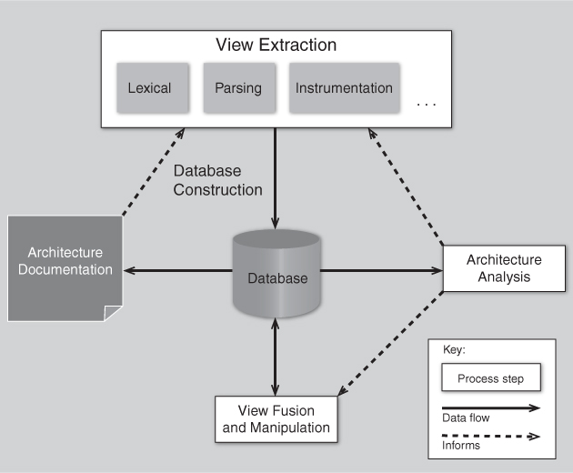
Figure 20.1. Architecture reconstruction process
All of these activities are greatly facilitated by engaging people who are familiar with the system. They can provide insights about what to look for—that is, what views are amenable to extraction—and provide a guided approach to view fusion and analysis. They can also point out or explain exceptions to the design rules (which will show up as violations of the hypotheses during the analysis phase). If the experts are long gone, reconstruction is still possible, but it may well require more backtracking from incorrect initial guesses.
20.2. Raw View Extraction
Raw view extraction involves analyzing a system’s existing design and implementation artifacts to construct one or more models of it. The result is a set of information that is used in the view fusion activity to construct more-refined views of the system that directly support the goals of the reconstruction, goals such as these:
• Extracting and representing a target set of architectural views, to support the overall architecture documentation effort.
• Answering specific questions about the architecture. For example, “What components are potentially affected if I choose to rewrite component X?” or “How can I refactor my layering to remove cyclic dependencies?”
The raw view extraction process is a blend of the ideal (what information do you want to discover about the architecture that will most help you meet the goals of your reconstruction effort?) and the practical (what information can your available tools actually extract and present?).
From the source artifacts (code, header files, build files, and so on) and other artifacts (e.g., execution traces), you can identify and capture the elements of interest within the system (e.g., files, functions, variables) and their relationships to obtain several base system views. Table 20.1 shows a typical list of the elements and several relationships among them that might be extracted.
Table 20.1. Examples of Extracted Elements and Relations
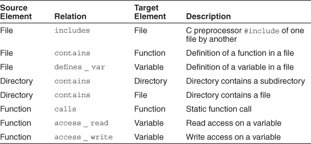
Each of the relationships between the elements gives different information about the system:
• The calls relationship between functions helps us build a call graph.
• The includes relationship between the files gives us a set of dependencies between system files.
• The access_read and access_write relationships between functions and variables show us how data is used. Certain functions may write a set of data and others may read it. This information is used to determine how data is passed between various parts of the system. We can determine whether or not a global data store is used or whether most information is passed through function calls.
• Certain elements or subsystems may be stored in particular directories, and capturing relations such as dir_contains_file and dir_contains_dir is useful when trying to identify elements later.
• If the system to be reconstructed is object oriented, classes and methods are added to the list of elements to be extracted, and relationships such as class_is_subclass_of_class and class_contains_method are extracted and used.
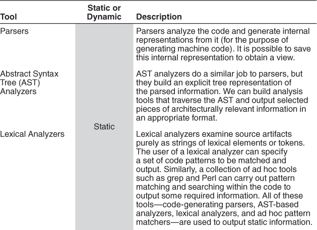
Information obtained can be categorized as either static or dynamic. Static information is obtained by observing only the system artifacts, while dynamic information is obtained by observing how the system runs. The goal is to fuse both to create more accurate system views.
If the architecture of the system changes at runtime, that runtime configuration should be captured and used when carrying out the reconstruction. For example, in some systems a configuration file is read in by the system at startup, or a newly started system examines its operating environment, and certain elements are executed or connections are made as a result.
Another reason to capture dynamic information is that some architecturally relevant information may not exist in the source artifacts because of late binding. Examples of late binding include the following:
• Polymorphism
• Function pointers
• Runtime parameterization
• Plug-ins
• Service interactions mediated by brokers
Further, the precise topology of a system may not be determined until runtime. For example, in peer-to-peer systems, service-oriented architectures, and cloud computing, the topology of the system is established dynamically, depending on the availability, loading, and even dynamic pricing of system resources. The topology of such systems cannot be directly recovered from their source artifacts and hence cannot be reverse-engineered using static extraction tools.
Therefore, it may be necessary to use tools that can generate dynamic information about the system (e.g., profiling tools, instrumentation that generates runtime traces, or aspects in an aspect-oriented programming language that can monitor dynamic activity). Of course, this requires that such tools be available on the platforms on which the system executes. Also, it may be difficult to collect the results from code instrumentation. For example, embedded systems often have no direct way to output such information.
Table 20.2 summarizes some of the common categories of tools that might be used to populate the views loaded into the reconstruction database.
Table 20.2. Tool Categories for Populating Reconstructed Architecture Views
Tools to analyze design models, build files, and executables can also be used to extract further information as required. For instance, build files include information on module or file dependencies that exist within the system, and this information may not be reflected in the source code, or anywhere else.
An additional activity that is often required prior to loading a raw view into the database is to prune irrelevant information. For example, in a C code base there may be several main() routines, but only one of those (and its resulting call graph) will be of concern for analysis. The others may be for test harnesses and other utility functions. Similarly if you are building or using libraries that are operating-system specific, you may only be interested in a specific OS (e.g., Linux) and thus want to discard the libraries for other platforms.
20.3. Database Construction
Some of the information extracted from the raw view extraction phase, while necessary for the process of reconstruction, may be too specific to aid in architectural understanding. Consider Figure 20.2. In this figure we show a set of facts extracted from a code base consisting of classes and methods, and inclusion and calling relations. Each element is plotted on a grid and each relation is drawn as a line between the elements. This view, while accurate, provides no insight into the overarching abstractions or coarse-grained structures present in the architecture.
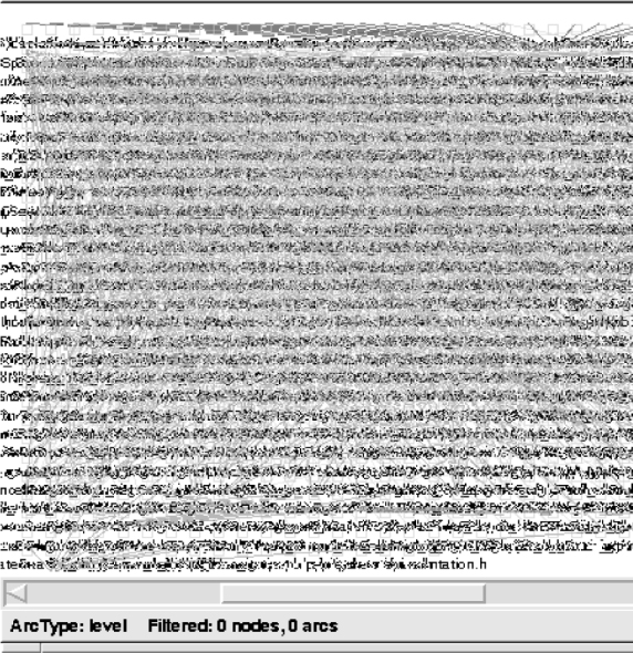
Figure 20.2. A raw extracted view: white noise
Thus we need to manipulate such raw views, to collapse information (for example, hiding methods inside class definitions), and to show abstractions (for example, showing all of the connections between business objects and user interface objects, or identifying distinct layers).
It is helpful to use a database to store the extracted information because the amount of information being stored is large, and the manipulations of the data are tedious and error-prone if done manually. Some reverse-engineering tools, such as Lattix, SonarJ, and Structure101, fully encapsulate the database, and so the user of the tool need not be concerned with its operation. However, those who are using a suite of tools together—a workbench—will need to choose a database and decide on internal representations of the views.
20.4. View Fusion
Once the raw facts have been extracted and stored in a database, the reconstructor can now perform view fusion. In this phase, the extracted views are manipulated to create fused views. Fused views combine information from one or more extracted views, each of which may contain specialized information. For example, a static call view might be fused with a dynamic call view. One might want to combine these two views because a static call view will show all explicit calls (where method A calls method B) but will miss calls that are made via late binding mechanisms. A dynamically extracted call graph will never miss a call that is made during an execution, but it suffers the “testing” problem: it will only report results from those paths through the system that are traversed during its execution. So a little-used part of the system—perhaps for initialization or error recovery—might not show up in the dynamic view. Therefore we fuse these two views to produce a more complete and more accurate graph of system relationships.
The process of creating a fused view is the process of creating a hypothesis about the architecture and a visualization of it to aid in analysis. These hypotheses result in new aggregations that show various abstractions or clusterings of the elements (which may be source artifacts or previously identified abstractions). By interpreting these fused views and analyzing them, it is possible to produce hypothesized architectural views of the system. These views can be interpreted, further refined, or rejected. There are no universal completion criteria for this process; it is complete when the architectural representation is sufficient to support the analysis needs of its stakeholders.
For example, Figure 20.3 shows the early results of interacting with the tool SonarJ. SonarJ first extracts facts from a set of source code files (in this case, written in Java) and lets you define a set of layers and vertical slices through those layers in a system. SonarJ will then instantiate the user-specified definitions of layers and slices and populate them with the extracted software elements.
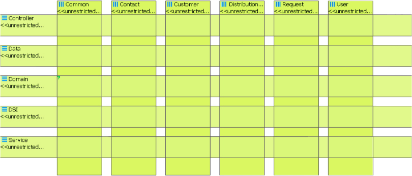
Figure 20.3. Hypothesized layers and vertical slices
In the figure there are five layers: Controller, Data, Domain, DSI, and Service. And there are six vertical slices defined that span these layers: Common, Contact, Customer, Distribution, Request, and User. At this point, however, there are no relationships between the layers or vertical slides shown—this is merely an enumeration of the important system abstractions.
20.5. Architecture Analysis: Finding Violations
Consider the following situation: You have designed an architecture but you have suspicions that the developers are not faithfully implementing what you developed. They may do this out of ignorance, or because they have differing agendas for the system, or simply because they were rushing to meet a deadline and ignored any concern not on their critical path. Whatever the root cause, this divergence of the architecture and the implementation spells problems for you, the architect. So how do you test and ensure conformance to the design?
There are two major possibilities for maintaining conformance between code and architecture:
• Conformance by construction. Ensuring consistency by construction—that is, automatically generating a substantial part of the system based on an architectural specification—is highly desirable because tools can guarantee conformance. Unfortunately, this approach has limited applicability. It can only be applied in situations where engineers can employ specific architecture-based development tools, languages, and implementation strategies. For systems that are composed of existing parts or that require a style of architecture or implementation outside those supported by generation tools, this approach does not apply. And this is the vast majority of systems.
• Conformance by analysis. This technique aims to ensure conformance by analyzing (reverse-engineering) system information to flag nonconforming elements, so that they can be fixed: brought into conformance. When an implementation is sufficiently constrained so that modularization and coding patterns can be identified with architectural elements, this technique can work well. Unfortunately, however, the technique is limited in its applicability. There is an inherent mismatch between static, code-based structures such as classes and packages (which are what programmers see) and the runtime structures, such as processes, threads, clients, servers, and databases, that are the essence of most architectural descriptions. Further complicating this analysis, the actual runtime structures may not be known or established until the program executes: clients and servers may come and go dynamically, components not under direct control of the implementers may be dynamically loaded, and so forth.
We will focus on the second option: conformance by analysis.
In the previous step, view fusion gave us a set of hypotheses about the architecture. These hypotheses take the form of architectural elements (sometimes aggregated, such as layers) and the constraints and relationships among them. These hypotheses need to be tested to see if they are correct—to see if they conform with the architect’s intentions. That is the function of the analysis step.
Figure 20.4 shows the results of adding relationships and constraints to the architecture initially created in Figure 20.3. These relationship and constraints are information added by the architect, to reflect the design intent. In this example, the architect has indicated the relationships between the layers of Figure 20.3. These relationships are indicated by the directed lines drawn between the layers (and vertical slices). Using these relationships and constraints, a tool such as SonarJ is able to automatically detect and report violations of the layering in the software.
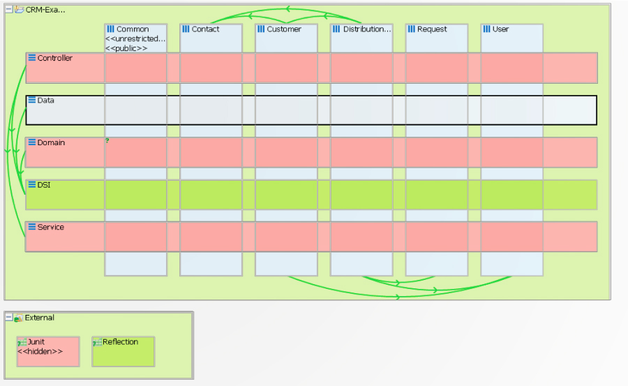
Figure 20.4. Layers, vertical slices, relationships, and constraints
We can now see that the Data layer (row 2 in Figure 20.4) can access, and hence depends on, the DSI layer. We can further see that it may not access, and has no dependencies on, Domain, Service, or Controller (rows 1, 3, and 5 in the figure).
In addition we can see that the JUnit component in the “External” component is defined to be inaccessible. This is an example of an architectural constraint that is meant to pervade the entire system: no portion of the application should depend upon JUnit, because this should only be used by test code.
Figure 20.5 shows an example of an architecture violation of the previous restriction. This violation is found by SonarJ by searching through its database, applying the user-defined patterns, and finding violations of those patterns. In this figure you can see an arc between the Service layer and JUnit. This arc is highlighted to indicate that this is an illegal dependency and an architectural violation. (This figure also shows some additional dependencies, to external modules.)
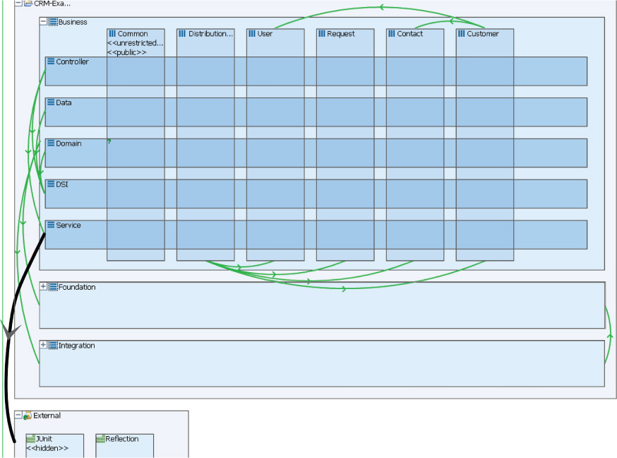
Figure 20.5. Highlighting an architecture violation
Architecture reconstruction is a means of testing the conformance to such constraints. The preceding example showed how these constraints might be detected and enforced using static code analysis. But static analysis is primarily useful for understanding module structures. What if one needed to understand runtime information, as represented by C&C structures?
In the example given in Figure 20.6, an architecture violation was discovered via dynamic analysis, using the research DiscoTect system. In this case an analysis of the runtime architecture of the Duke’s Bank application—a simple Enterprise JavaBeans (EJB) banking application created by Sun Microsystems as a demonstration of EJB functionality—was performed. The code was “instrumented” using AspectJ; instrumentation aspects were woven into the compiled bytecode of the EJB application. These aspects emitted events when methods entered or exited and when objects were constructed.
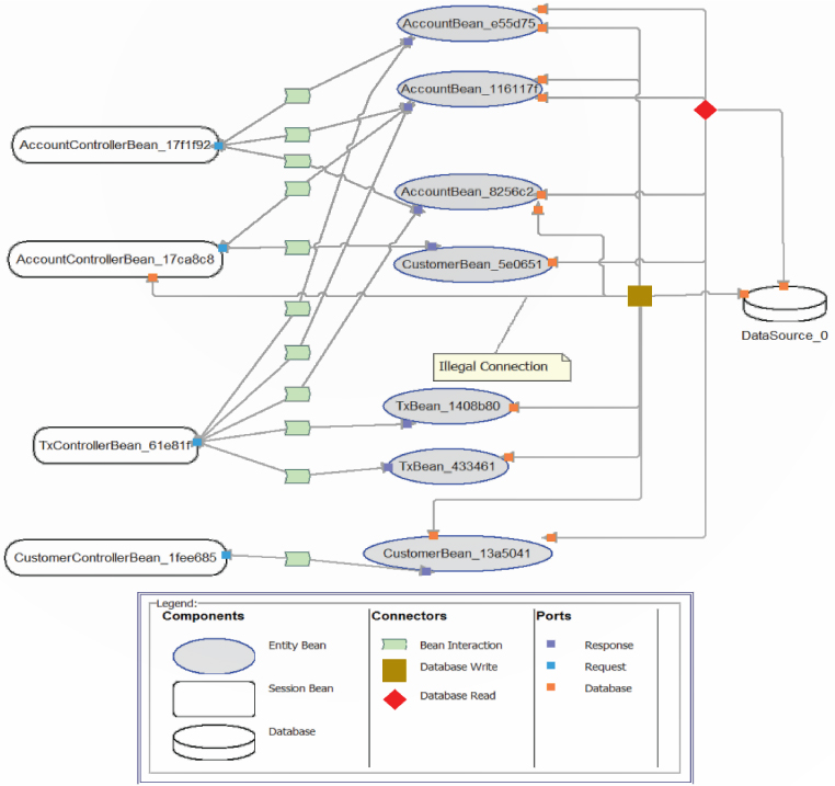
Figure 20.6. An architecture violation discovered by dynamic analysis
Figure 20.6 shows that a “database write” connector was discovered in the dynamic analysis of the architecture. Sun’s EJB specification and its documented architecture of Duke’s Bank forbid such connections. All database access is supposed to be managed by entity beans, and only by entity beans. Such architectural violations are difficult to find in the source code—often just a single line of code is involved—and yet can substantially affect the quality attributes of the resulting system.
20.6. Guidelines
The following are a set of guidelines for the reconstruction process:
• Have a goal and a set of objectives or questions in mind before undertaking an architecture reconstruction project. In the absence of these, a lot of effort could be spent on extracting information and generating architecture views that may not be helpful or serve any useful purpose.
• Obtain some representation, however coarse, of the system before beginning the detailed reconstruction process. This representation serves several purposes, including the following:
• It identifies what information needs to be extracted from the system.
• It guides the reconstructor in determining what to look for in the architecture and what views to generate.
Identifying layers is a good place to start.
• In many cases, the existing documentation for a system may not accurately reflect the system as it is implemented. Therefore it may be necessary to disregard the existing documentation and use it only to generate the high-level views of the system, because it should give an indication of the high-level concepts.
• Tools can support the reconstruction effort and shorten the reconstruction process, but they cannot do an entire reconstruction effort automatically. The work involved in the effort requires the involvement of people (architects, maintainers, and developers) who are familiar with the system. It is important to get these people involved in the effort at an early stage as it helps the reconstructor get a better understanding of the system being reconstructed.
20.7. Summary
Architecture reconstruction and architecture conformance are crucial tools in the architect’s toolbox to ensure that a system is built the way it was designed, and that it evolves in a way that is consistent with its creators’ intentions. All nontrivial long-lived systems evolve: the code and the architecture both evolve. This is a good thing. But if the code evolves in an ad hoc manner, the result will be the big ball of mud, and the system’s quality attributes will inevitably suffer. The only defense against this erosion is consistent attention to architecture quality, which implies the need to maintain architecture conformance.
The results of architectural reconstruction can be used in several ways:
• If no documentation exists or if it is seriously out of date, the recovered architectural representation can be used as a basis for documenting the architecture, as discussed in Chapter 18.
• It can be used to recover the as-built architecture, or to check conformance against an “as-designed” architecture. Conformance checking assures us that our developers and maintainers have followed the architectural edicts set forth for them and are not eroding the architecture by breaking down abstractions, bridging layers, compromising information hiding, and so forth.
• The reconstruction can be used as the basis for analyzing the architecture or as a starting point for reengineering the system to a new desired architecture.
• Finally, the representation can be used to identify elements for reuse or to establish an architecture-based software product line (see Chapter 25).
The software architecture reconstruction process comprises the following phases:
1. Raw view extraction. In the raw view extraction phase, raw information about the architecture is obtained from various sources, primarily source code, execution traces, and build scripts. Each of these sets of raw information is called a view.
2. Database construction. The database construction phase involves converting the extracted information into a standard form (because the various extraction tools may each produce their own form of output) and populating a reconstruction database with this information.
3. View fusion. The view fusion phase combines views of the information stored in the database.
4. Architecture analysis. View fusion has given us a set of hypotheses about the architecture. These hypotheses take the form of architectural elements (sometimes aggregated, such as layers) and the constraints and relationships among them. These hypotheses need to be tested to see if they are correct, and that is the function of the analysis step.
20.8. For Further Reading
The Software Engineering Institute (SEI) has developed two reconstruction workbenches: Dali and Armin. Dali was our first attempt at creating a workbench for architecture recovery and conformance [Kazman 99]. Armin, a complete rewrite and rethink of Dali, is described in [O’Brien 03].
Both Armin and Dali were primarily focused on module structures of an architecture. A later tool, called DiscoTect, was aimed at discovering C&C structures. This is described in [Schmerl 06].
Many other architecture reverse-engineering tools have been created. A few of the notable ones created in academia are [van Deursen 04], [Murphy 01], and [Storey 97].
In addition there are a number of commercial architecture extraction and reconstruction tools that have been slowly gaining market acceptance in the past decade. Among these are the following:
• SonarJ (www.hello2morrow.com)
• Lattix (www.lattix.com)
• Understand (www.scitools.com)
Cai et al. [Cai 2011] compellingly demonstrate the need for architecture conformance testing in an experimental study that they conducted, wherein they found that software engineering students, given UML designs for a variety of relatively simple systems, violate those designs over 70 percent of the time.
Finally, the set of guidelines presented in this chapter for how to go about reconstructing an architecture was excerpted from [Kazman 02].
20.9. Discussion Questions
1. Suppose that for a given system you wanted to extract the architectural structures (as discussed in Chapter 1) listed in the table rows below. For each row, fill in each column to appraise each strategy listed in the columns. “VH” (very high) means the strategy would be very effective at extracting this structure; “VL” means it would be very ineffective; “H,” M,” and “L” have the obvious in-between values.
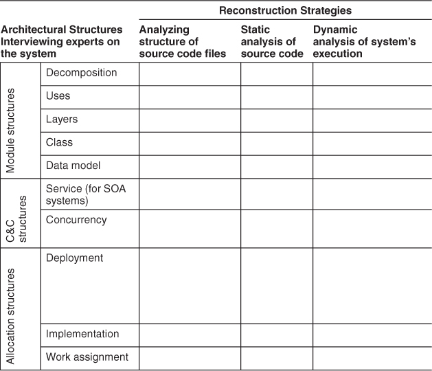
2. Recall that in layered systems, the relationship among layers is allowed to use. Also recall that it is possible for one piece of software to use another piece without actually calling it—for example, by depending on it leaving some shared resource in a usable state. Does this interpretation change your answer above for the “Uses” and “Layers” structures?
3. What inferences can you make about a system’s module structures from examining a set of behavioral traces gathered dynamically?
4. Suppose you believe that the architecture for a system follows a broker pattern. What information would you want to extract from the source code to confirm or refute this hypothesis? What behavioral or interaction pattern would you expect to observe at runtime?
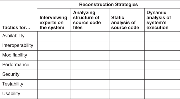
5. Suppose you hypothesize that a system makes use of particular tactics to achieve a particular quality attribute. Fill in the columns of the table below to show how you would go about verifying your hypothesis. (Begin by filling in column 1 with a particular tactic for the named quality attribute.)
6. Suppose you want to confirm that developers and maintainers had remained faithful to an architecture over the lifetime of the system. Describe the reconstruction and/or auditing processes you would undertake.