
18. Documenting Software Architectures
If it is not written down, it does not exist.
—Philippe Kruchten
Even the best architecture, the most perfectly suited for the job, will be essentially useless if the people who need to use it do not know what it is; cannot understand it well enough to use, build, or modify it; or (worst of all) misunderstand it and apply it incorrectly. And all of the effort, analysis, hard work, and insightful design on the part of the architecture team will have been wasted. They might as well have gone on vacation for all the good their architecture will do.
Creating an architecture isn’t enough. It has to be communicated in a way to let its stakeholders use it properly to do their jobs. If you go to the trouble of creating a strong architecture, one that you expect to stand the test of time, then you must go to the trouble of describing it in enough detail, without ambiguity, and organizing it so that others can quickly find and update needed information.
Documentation speaks for the architect. It speaks for the architect today, when the architect should be doing other things besides answering a hundred questions about the architecture. And it speaks for the architect tomorrow, when he or she has left the project and now someone else is in charge of its evolution and maintenance.
The sad truth is that architectural documentation today, if it is done at all, is often treated as an afterthought, something people do because they have to. Maybe a contract requires it. Maybe a customer demands it. Maybe a company’s standard process calls for it. In fact, these may all be legitimate reasons. But none of them are compelling enough to produce high-quality documentation. Why should the architect spend valuable time and energy just so a manager can check off a deliverable?
The best architects produce good documentation not because it’s “required” but because they see that it is essential to the matter at hand—producing a high-quality product, predictably and with as little rework as possible. They see their immediate stakeholders as the people most intimately involved in this undertaking: developers, deployers, testers, and analysts.
But architects also see documentation as delivering value to themselves. Documentation serves as the receptacle to hold the results of major design decisions as they are confirmed. A well-thought-out documentation scheme can make the process of design go much more smoothly and systematically. Documentation helps the architect(s) reason about the architecture design and communicate it while the architecting is in progress, whether in a six-month design phase or a six-day Agile sprint.
18.1. Uses and Audiences for Architecture Documentation
Architecture documentation must serve varied purposes. It should be sufficiently transparent and accessible to be quickly understood by new employees. It should be sufficiently concrete to serve as a blueprint for construction. It should have enough information to serve as a basis for analysis.
Architecture documentation is both prescriptive and descriptive. For some audiences, it prescribes what should be true, placing constraints on decisions yet to be made. For other audiences, it describes what is true, recounting decisions already made about a system’s design.
The best architecture documentation for, say, performance analysis may well be different from the best architecture documentation we would wish to hand to an implementer. And both of these will be different from what we put in a new hire’s “welcome aboard” package or a briefing we put together for an executive. When planning and reviewing documentation, you need to ensure support for all the relevant needs.
We can see that many different kinds of people are going to have a vested interest in an architecture document. They hope and expect that the architecture document will help them do their respective jobs. Understanding their uses of architecture documentation is essential, as those uses determine the important information to capture.
Fundamentally, architecture documentation has three uses:
1. Architecture documentation serves as a means of education. The educational use consists of introducing people to the system. The people may be new members of the team, external analysts, or even a new architect. In many cases, the “new” person is the customer to whom you’re showing your solution for the first time, a presentation you hope will result in funding or go-ahead approval.
2. Architecture documentation serves as a primary vehicle for communication among stakeholders. An architecture’s precise use as a communication vehicle depends on which stakeholders are doing the communicating.
Perhaps one of the most avid consumers of architecture documentation is none other than the architect in the project’s future. The future architect may be the same person or may be a replacement, but in either case he or she is guaranteed to have an enormous stake in the documentation. New architects are interested in learning how their predecessors tackled the difficult issues of the system and why particular decisions were made. Even if the future architect is the same person, he or she will use the documentation as a repository of thought, a storehouse of design decisions too numerous and hopelessly intertwined to ever be reproducible from memory alone. See the sidebar “Schmucks and Jerks.”
3. Architecture documentation serves as the basis for system analysis and construction. Architecture tells implementers what to implement. Each module has interfaces that must be provided and uses interfaces from other modules. Not only does this provide instructions about the provided and used interfaces, but it also determines with what other teams the development team for the module must communicate.
During development, an architecture can be very complex, with many issues left to resolve. Documentation can serve as a receptacle for registering and communicating these issues that might otherwise be overlooked.
For those interested in the ability of the design to meet the system’s quality objectives, the architecture documentation serves as the fodder for evaluation. It must contain the information necessary to evaluate a variety of attributes, such as security, performance, usability, availability, and modifiability.
For system builders who use automatic code-generation tools, the documentation may incorporate the models used for generation. These models provide guidance to those who wish to understand the behavior of the module in more detail than is normally documented but in less detail than examining the code would provide.
18.2. Notations for Architecture Documentation
Notations for documenting views differ considerably in their degree of formality. Roughly speaking, there are three main categories of notation:
• Informal notations. Views are depicted (often graphically) using general-purpose diagramming and editing tools and visual conventions chosen for the system at hand. The semantics of the description are characterized in natural language, and they cannot be formally analyzed. In our experience, the most common tool for informal notations is PowerPoint.
• Semiformal notations. Views are expressed in a standardized notation that prescribes graphical elements and rules of construction, but it does not provide a complete semantic treatment of the meaning of those elements. Rudimentary analysis can be applied to determine if a description satisfies syntactic properties. UML is a semiformal notation in this sense.
• Formal notations. Views are described in a notation that has a precise (usually mathematically based) semantics. Formal analysis of both syntax and semantics is possible. There are a variety of formal notations for software architecture available. Generally referred to as architecture description languages (ADLs), they typically provide both a graphical vocabulary and an underlying semantics for architecture representation. In some cases these notations are specialized to particular architectural views. In others they allow many views, or even provide the ability to formally define new views. The usefulness of ADLs lies in their ability to support automation through associated tools: automation to provide useful analysis of the architecture or assist in code generation. In practice, the use of such notations is rare.
Determining which form of notation to use involves making several tradeoffs. Typically, more formal notations take more time and effort to create and understand, but they repay this effort in reduced ambiguity and more opportunities for analysis. Conversely, more informal notations are easier to create, but they provide fewer guarantees.
Regardless of the level of formality, always remember that different notations are better (or worse) for expressing different kinds of information. Formality aside, no UML class diagram will help you reason about schedulability, nor will a sequence chart tell you very much about the system’s likelihood of being delivered on time. You should choose your notations and representation languages always keeping in mind the important issues you need to capture and reason about.
18.3. Views
Perhaps the most important concept associated with software architecture documentation is that of the view. A software architecture is a complex entity that cannot be described in a simple one-dimensional fashion. A view is a representation of a set of system elements and relations among them—not all system elements, but those of a particular type. For example, a layered view of a system would show elements of type “layer”—that is, it would show the system’s decomposition into layers—and the relations among those layers. A pure layered view would not, however, show the system’s services, or clients and servers, or data model, or any other type of element.
Thus, views let us divide the multidimensional entity that is a software architecture into a number of (we hope) interesting and manageable representations of the system. The concept of views gives us our most fundamental principle of architecture documentation:
Documenting an architecture is a matter of documenting the relevant views and then adding documentation that applies to more than one view.
This maxim gives our approach to documentation its name: Views and Beyond.
What are the relevant views? This depends entirely on your goals. As we saw previously, architecture documentation can serve many purposes: a mission statement for implementers, a basis for analysis, the specification for automatic code generation, the starting point for system understanding and asset recovery, or the blueprint for project planning.
Different views also expose different quality attributes to different degrees. Therefore, the quality attributes that are of most concern to you and the other stakeholders in the system’s development will affect the choice of what views to document. For instance, a layered view will let you reason about your system’s portability, a deployment view will let you reason about your system’s performance and reliability, and so forth.
Different views support different goals and uses. This is why we do not advocate a particular view or collection of views. The views you should document depend on the uses you expect to make of the documentation. Different views will highlight different system elements and relations. How many different views to represent is the result of a cost/benefit decision. Each view has a cost and a benefit, and you should ensure that the benefits of maintaining a particular view outweigh its costs.
Views may be driven by the need to document a particular pattern in your design. Some patterns are composed of modules, others of components and connectors, and still others have deployment considerations. Module views, component-and-connector (C&C) views, and allocation views are the appropriate mechanisms for representing these considerations.
Module Views
A module is an implementation unit that provides a coherent set of responsibilities. A module might take the form of a class, a collection of classes, a layer, an aspect, or any decomposition of the implementation unit. Example module views are decomposition, uses, and layers. Every module has a collection of properties assigned to it. These properties are intended to express the important information associated with the module, as well as constraints on the module. Sample properties are responsibilities, visibility information, and revision history. The relations that modules have to one another include is part of, depends on, and is a.
The way in which a system’s software is decomposed into manageable units remains one of the important forms of system structure. At a minimum, this determines how a system’s source code is decomposed into units, what kinds of assumptions each unit can make about services provided by other units, and how those units are aggregated into larger ensembles. It also includes global data structures that impact and are impacted by multiple units. Module structures often determine how changes to one part of a system might affect other parts and hence the ability of a system to support modifiability, portability, and reuse.
It is unlikely that the documentation of any software architecture can be complete without at least one module view.
Table 18.1 summarizes the elements, relations, constraints, and purpose of the module views in general. Later we provide this information specific to each of a number of often used module views.
Table 18.1. Summary of the Module Views
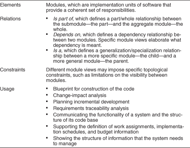
Properties of modules that help to guide implementation or are input to analysis should be recorded as part of the supporting documentation for a module view. The list of properties may vary but is likely to include the following:
• Name. A module’s name is, of course, the primary means to refer to it. A module’s name often suggests something about its role in the system. In addition, a module’s name may reflect its position in a decomposition hierarchy; the name A.B.C, for example, refers to a module C that is a submodule of a module B, itself a submodule of A.
• Responsibilities. The responsibility property for a module is a way to identify its role in the overall system and establishes an identity for it beyond the name. Whereas a module’s name may suggest its role, a statement of responsibility establishes it with much more certainty. Responsibilities should be described in sufficient detail to make clear to the reader what each module does.
• Visibility of interface(s). When a module has submodules, some interfaces of the submodules are public and some may be private; that is, the interfaces are used only by the submodules within the enclosing parent module. These private interfaces are not visible outside that context.
• Implementation information. Modules are units of implementation. It is therefore useful to record information related to their implementation from the point of view of managing their development and building the system that contains them. This might include the following:
• Mapping to source code units. This identifies the files that constitute the implementation of a module. For example, a module Account, if implemented in Java, might have several files that constitute its implementation: IAccount.java (an interface), AccountImpl.java (the implementation of Account functionality), AccountBean.java (a class to hold the state of an account in memory), AccountOrmMapping.xml (a file that defines the mapping between AccountBean and a database table—object-relational mapping), and perhaps even a unit test AccountTest.java.
• Test information. The module’s test plan, test cases, test scaffolding, and test data are important to document. This information may simply be a pointer to the location of these artifacts.
• Management information. A manager may need information about the module’s predicted schedule and budget. This information may simply be a pointer to the location of these artifacts.
• Implementation constraints. In many cases, the architect will have an implementation strategy in mind for a module or may know of constraints that the implementation must follow.
• Revision history. Knowing the history of a module including authors and particular changes may help when you perform maintenance activities.
Because modules partition the system, it should be possible to determine how the functional requirements of a system are supported by module responsibilities. Module views that show dependencies among modules or layers (which are groups of modules that have a specific pattern of allowed usage) provide a good basis for change-impact analysis. Modules are typically modified as a result of problem reports or change requests. Impact analysis requires a certain degree of design completeness and integrity of the module description. In particular, dependency information has to be available and correct to be able to create useful results.
A module view can be used to explain the system’s functionality to someone not familiar with it. The various levels of granularity of the module decomposition provide a top-down presentation of the system’s responsibilities and therefore can guide the learning process. For a system whose implementation is already in place, module views, if kept up to date, are helpful, as they explain the structure of the code base to a new developer on the team. Thus, up-to-date module views can simplify and regularize system maintenance.
On the other hand, it is difficult to use the module views to make inferences about runtime behavior, because these views are just a static partition of the functions of the software. Thus, a module view is not typically used for analysis of performance, reliability, and many other runtime qualities. For those, we rely on component-and-connector and allocation views.
Module views are commonly mapped to component-and-connector views. The implementation units shown in module views have a mapping to components that execute at runtime. Sometimes, the mapping is quite straightforward, even one-to-one for small, simple applications. More often, a single module will be replicated as part of many runtime components, and a given component could map to several modules. Module views also provide the software elements that are mapped to the diverse nonsoftware elements of the system environment in the various allocation views.
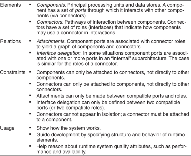
Component-and-Connector Views
Component-and-connector views show elements that have some runtime presence, such as processes, objects, clients, servers, and data stores. These elements are termed components. Additionally, component-and-connector views include as elements the pathways of interaction, such as communication links and protocols, information flows, and access to shared storage. Such interactions are represented as connectors in C&C views. Sample C&C views are service-oriented architecture (SOA), client-server, or communicating process views.
Components have interfaces called ports. A port defines a point of potential interaction of a component with its environment. A port usually has an explicit type, which defines the kind of behavior that can take place at that point of interaction. A component may have many ports of the same type, each forming a different input or output channel at runtime. In this respect ports differ from interfaces of modules, whose interfaces are never replicated. You can annotate a port with a number or range of numbers to indicate replication; for example, “1..4” might mean that an interface could be replicated up to four times. A component’s ports should be explicitly documented, by showing them in the diagram and defining them in the diagram’s supporting documentation.
A component in a C&C view may represent a complex subsystem, which itself can be described as a C&C subarchitecture. This subarchitecture can be depicted graphically in situ when the substructure is not too complex, by showing it as nested inside the component that it refines. Often, however, it is documented separately. A component’s subarchitecture may employ a different pattern than the one in which the component appears.
Connectors are the other kind of element in a C&C view. Simple examples of connectors are service invocation; asynchronous message queues; event multicast supporting publish-subscribe interactions; and pipes that represent asynchronous, order-preserving data streams. Connectors often represent much more complex forms of interaction, such as a transaction-oriented communication channel between a database server and a client, or an enterprise service bus that mediates interactions between collections of service users and providers.
Connectors have roles, which are its interfaces, defining the ways in which the connector may be used by components to carry out interaction. For example, a client-server connector might have invokes-services and provides-services roles. A pipe might have writer and reader roles. Like component ports, connector roles differ from module interfaces in that they can be replicated, indicating how many components can be involved in its interaction. A publish-subscribe connector might have many instances of the publisher and subscriber roles.
Like components, complex connectors may in turn be decomposed into collections of components and connectors that describe the architectural substructure of those connectors. Connectors need not be binary. That is, they need not have exactly two roles. For example, a publish-subscribe connector might have an arbitrary number of publisher and subscriber roles. Even if the connector is ultimately implemented using binary connectors, such as a procedure call, it can be useful to adopt n-ary connector representations in a C&C view. Connectors embody a protocol of interaction. When two or more components interact, they must obey conventions about order of interactions, locus of control, and handling of error conditions and timeouts. The protocol of interaction should be documented.
The primary relation within a C&C view is attachment. Attachments indicate which connectors are attached to which components, thereby defining a system as a graph of components and connectors. Specifically, an attachment is denoted by associating (attaching) a component’s port to a connector’s role. A valid attachment is one in which the ports and roles are compatible with each other, under the semantic constraints defined by the view. Compatibility often is defined in terms of information type and protocol. For example, in a call-return architecture, you should check to make sure that all “calls” ports are attached to some call-return connector. At a deeper semantic level, you should check to make sure that a port’s protocol is consistent with the behavior expected by the role to which it is attached.
An element (component or connector) of a C&C view will have various associated properties. Every element should have a name and type. Additional properties depend on the type of component or connector. Define values for the properties that support the intended analyses for the particular C&C view. For example, if the view will be used for performance analysis, latencies, queue capacities, and thread priorities may be necessary. The following are examples of some typical properties and their uses:
• Reliability. What is the likelihood of failure for a given component or connector? This property might be used to help determine overall system availability.
• Performance. What kinds of response time will the component provide under what loads? What kind of bandwidth, latency, jitter, transaction volume, or throughput can be expected for a given connector? This property can be used with others to determine system-wide properties such as response times, throughput, and buffering needs.
• Resource requirements. What are the processing and storage needs of a component or a connector? This property can be used to determine whether a proposed hardware configuration will be adequate.
• Functionality. What functions does an element perform? This property can be used to reason about overall computation performed by a system.
• Security. Does a component or a connector enforce or provide security features, such as encryption, audit trails, or authentication? This property can be used to determine system security vulnerabilities.
• Concurrency. Does this component execute as a separate process or thread? This property can help to analyze or simulate the performance of concurrent components and identify possible deadlocks.
• Modifiability. Does the messaging structure support a structure to cater for evolving data exchanges? Can the components be adapted to process those new messages? This property can be defined to extend the functionality of a component.
• Tier. For a tiered topology, what tier does the component reside in? This property helps to define the build and deployment procedures, as well as platform requirements for each tier.
C&C views are commonly used to show to developers and other stakeholders how the system works—one can “animate” or trace through a C&C view, showing an end-to-end thread of activity. C&C views are also used to reason about runtime system quality attributes, such as performance and availability. In particular, a well-documented view allows architects to predict overall system properties such as latency or reliability, given estimates or measurements of properties of the individual elements and their interactions.
Table 18.2 summarizes the elements, relations, and properties that can appear in C&C views. This table is followed by a more detailed discussion of these concepts, together with guidelines concerning their documentation.
Table 18.2. Summary of Component-and-Connector Views
Notations for C&C Views
As always, box-and-line drawings are available to represent C&C views. Although informal notations are limited in the semantics that can be conveyed, following some simple guidelines can lend rigor and depth to the descriptions. The primary guideline is simple: assign each component type and each connector type a separate visual form (symbol), and list each of the types in a key.
UML components are a good semantic match to C&C components because they permit intuitive documentation of important information like interfaces, properties, and behavioral descriptions. UML components also distinguish between component types and component instances, which is useful when defining view-specific component types.
UML ports are a good semantic match to C&C ports. A UML port can be decorated with a multiplicity, as shown in the left portion of Figure 18.1, though this is typically only done on component types. The number of ports on component instances, as shown in the right portion of Figure 18.1, is typically bound to a specific number. Components that dynamically create and manage a set of ports should retain a multiplicity descriptor on instance descriptions.
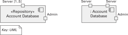
Figure 18.1. A UML representation of the ports on a C&C component type (left) and component instance (right). The Account Database component type has two types of ports, Server and Admin (noted by the boxes on the component’s border). The Server port is defined with a multiplicity, meaning that multiple instances of the port are permitted on any corresponding component instance.
While C&C connectors are as semantically rich as C&C components, the same is not true of UML connectors. UML connectors cannot have substructure, attributes, or behavioral descriptions. This makes choosing how to represent C&C connectors more difficult, as UML connectors are not always rich enough.
You should represent a “simple” C&C connector using a UML connector—a line. Many commonly used C&C connectors have well-known, application-independent semantics and implementations, such as function calls or data read operations. If the only information you need to supply is the type of the connector, then a UML connector is adequate. Call-return connectors can be represented by a UML assembly connector, which links a component’s required interface (socket) to the other component’s provided interface (lollipop). You can use a stereotype to denote the type of connector. If all connectors in a primary presentation are of the same type, you can note this once in a comment rather than explicitly on each connector to reduce visual clutter. Attachment is shown by connecting the endpoints of the connector to the ports of components. Connector roles cannot be explicitly represented with a UML connector because the UML connector element does not allow the inclusion of interfaces (unlike the UML port, which does allow interfaces). The best approximation is to label the connector ends and use these labels to identify role descriptions that must be documented elsewhere.
You should represent a “rich” C&C connector using a UML component, or by annotating a line UML connector with a tag or other auxiliary documentation that explains the meaning of the complex connector.
Allocation Views
Allocation views describe the mapping of software units to elements of an environment in which the software is developed or in which it executes. The environment might be the hardware, the operating environment in which the software is executed, the file systems supporting development or deployment, or the development organization(s).
Table 18.3 summarizes the characteristics of allocation views. Allocation views consist of software elements and environmental elements. Examples of environmental elements are a processor, a disk farm, a file or folder, or a group of developers. The software elements come from a module or C&C view.
Table 18.3. Summary of the Characteristics of Allocation Views
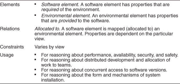
The relation in an allocation view is allocated to. We usually talk about allocation views in terms of a mapping from software elements to environmental elements, although the reverse mapping can also be relevant and interesting. A single software element can be allocated to multiple environmental elements, and multiple software elements can be allocated to a single environmental element. If these allocations change over time, either during development or execution of the system, then the architecture is said to be dynamic with respect to that allocation. For example, processes might migrate from one processor or virtual machine to another. Similarly modules might migrate from one development team to another.
Software elements and environmental elements have properties in allocation views. The usual goal of an allocation view is to compare the properties required by the software element with the properties provided by the environmental elements to determine whether the allocation will be successful or not. For example, to ensure a component’s required response time, it has to execute on (be allocated to) a processor that provides sufficiently fast processing power. For another example, a computing platform might not allow a task to use more than 10 kilobytes of virtual memory. An execution model of the software element in question can be used to determine the required virtual memory usage. Similarly, if you are migrating a module from one team to another, you might want to ensure that the new team has the appropriate skills and background knowledge.
Allocation views can depict static or dynamic views. A static view depicts a fixed allocation of resources in an environment. A dynamic view depicts the conditions and the triggers for which allocation of resources changes according to loading. Some systems recruit and utilize new resources as their load increases. An example is a load-balancing system in which new processes or threads are created on another machine. In this view, the conditions under which the allocation changes, the allocation of runtime software, and the dynamic allocation mechanism need to be documented. (Recall from Chapter 1 that one of the allocation structures is the work assignment structure, which allocates modules to teams for development. That relationship, too, can be allocated dynamically, depending on “load”—in this case, the load on development teams.)
Quality Views
Module, C&C, and allocation views are all structural views: They primarily show the structures that the architect has engineered into the architecture to satisfy functional and quality attribute requirements.
These views are excellent for guiding and constraining downstream developers, whose primary job it is to implement those structures. However, in systems in which certain quality attributes (or, for that matter, some other kind of stakeholder concerns) are particularly important and pervasive, structural views may not be the best way to present the architectural solution to those needs. The reason is that the solution may be spread across multiple structures that are inconvenient to combine (for example, because the element types shown in each are different).
Another kind of view, which we call a quality view, can be tailored for specific stakeholders or to address specific concerns. These quality views are formed by extracting the relevant pieces of structural views and packaging them together. Here are five examples:
• A security view can show all of the architectural measures taken to provide security. It would show the components that have some security role or responsibility, how those components communicate, any data repositories for security information, and repositories that are of security interest. The view’s context information would show other security measures (such as physical security) in the system’s environment. The behavior part of a security view would show the operation of security protocols and where and how humans interact with the security elements. It would also capture how the system would respond to specific threats and vulnerabilities.
• A communications view might be especially helpful for systems that are globally dispersed and heterogeneous. This view would show all of the component-to-component channels, the various network channels, quality-of-service parameter values, and areas of concurrency. This view can be used to analyze certain kinds of performance and reliability (such as deadlock or race condition detection). The behavior part of this view could show (for example) how network bandwidth is dynamically allocated.
• An exception or error-handling view could help illuminate and draw attention to error reporting and resolution mechanisms. Such a view would show how components detect, report, and resolve faults or errors. It would help identify the sources of errors and appropriate corrective actions for each. Root-cause analysis in those cases could be facilitated by such a view.
• A reliability view would be one in which reliability mechanisms such as replication and switchover are modeled. It would also depict timing issues and transaction integrity.
• A performance view would include those aspects of the architecture useful for inferring the system’s performance. Such a view might show network traffic models, maximum latencies for operations, and so forth.
These and other quality views reflect the documentation philosophy of ISO/IEC/IEEE standard 42010:2011, which prescribes creating views driven by stakeholder concerns about the architecture.
18.4. Choosing the Views
Documenting decisions during the design process (something we strongly recommend) produces views, which are the heart of an architecture document. It is most likely that these views are rough sketches more than finished products ready for public release; this will give you the freedom to back up and rethink design decisions that turn out to be problematic without having wasted time on broad dissemination and cosmetic polish. They are documented purely as your own memory aid.
By the time you’re ready to release an architecture document, you’re likely to have a fairly well-worked-out collection of architecture views. At some point you’ll need to decide which to take to completion, with how much detail, and which to include in a given release. You’ll also need to decide which views can be usefully combined with others, so as to reduce the total number of views in the document and reveal important relations among the views.
You can determine which views are required, when to create them, and how much detail to include if you know the following:
• What people, and with what skills, are available
• Which standards you have to comply with
• What budget is on hand
• What the schedule is
• What the information needs of the important stakeholders are
• What the driving quality attribute requirements are
• What the size of the system is
At a minimum, expect to have at least one module view, at least one C&C view, and for larger systems, at least one allocation view in your architecture document. Beyond that basic rule of thumb, however, there is a three-step method for choosing the views:
• Step 1. Build a stakeholder/view table. Enumerate the stakeholders for your project’s software architecture documentation down the rows. Be as comprehensive as you can. For the columns, enumerate the views that apply to your system. (Use the structures discussed in Chapter 1, the views discussed in this chapter, and the views that your design work in ADD has suggested as a starting list of candidates.) Some views (such as decomposition, uses, and work assignment) apply to every system, while others (various C&C views, the layered view) only apply to some systems. For the columns, make sure to include the views or view sketches you already have as a result of your design work so far.
Once you have the rows and columns defined, fill in each cell to describe how much information the stakeholder requires from the view: none, overview only, moderate detail, or high detail. The candidate view list going into step 2 now consists of those views for which some stakeholder has a vested interest.
• Step 2. Combine views. The candidate view list from step 1 is likely to yield an impractically large number of views. This step will winnow the list to manageable size. Look for marginal views in the table: those that require only an overview, or that serve very few stakeholders. Combine each marginal view with another view that has a stronger constituency.
• Step 3. Prioritize and stage. After step 2 you should have the minimum set of views needed to serve your stakeholder community. At this point you need to decide what to do first. What you do first depends on your project, but here are some things to consider:
• The decomposition view (one of the module views) is a particularly helpful view to release early. High-level (that is, broad and shallow) decompositions are often easy to design, and with this information the project manager can start to staff development teams, put training in place, determine which parts to outsource, and start producing budgets and schedules.
• Be aware that you don’t have to satisfy all the information needs of all the stakeholders to the fullest extent. Providing 80 percent of the information goes a long way, and this might be good enough so that the stakeholders can do their job. Check with the stakeholder to see if a subset of information would be sufficient. They typically prefer a product that is delivered on time and within budget over getting the perfect documentation.
• You don’t have to complete one view before starting another. People can make progress with overview-level information, so a breadth-first approach is often the best.
18.5. Combining Views
The basic principle of documenting an architecture as a set of separate views brings a divide-and-conquer advantage to the task of documentation, but if the views were irrevocably different, with no association with one another, nobody would be able to understand the system as a whole.
Because all views in an architecture are part of that same architecture and exist to achieve a common purpose, many of them have strong associations with each other. Managing how architectural structures are associated is an important part of the architect’s job, independent of whether any documentation of those structures exists.
Sometimes the most convenient way to show a strong association between two views is to collapse them into a single combined view, as dictated by step 2 of the three-step method just presented to choose the views. A combined view is a view that contains elements and relations that come from two or more other views. Combined views can be very useful as long as you do not try to overload them with too many mappings.
The easiest way to merge views is to create an overlay that combines the information that would otherwise have been in two separate views. This works well if the coupling between the two views is tight; that is, there are strong associations between elements in one view and elements in the other view. If that is the case, the structure described by the combined view will be easier to understand than the two views seen separately. For an example, see the overlay of decomposition and uses sketches shown in Figure 18.2. In an overlay, the elements and the relations keep the types as defined in their constituent views.
Figure 18.2. A decomposition view overlaid with “uses” information, to create a decomposition/uses overlay.
The views below often combine naturally:
• Various C&C views. Because C&C views all show runtime relations among components and connectors of various types, they tend to combine well. Different (separate) C&C views tend to show different parts of the system, or tend to show decomposition refinements of components in other views. The result is often a set of views that can be combined easily.
• Deployment view with either SOA or communicating-processes views. An SOA view shows services, and a communicating-processes view shows processes. In both cases, these are components that are deployed onto processors. Thus there is a strong association between the elements in these views.
• Decomposition view and any of work assignment, implementation, uses, or layered views. The decomposed modules form the units of work, development, and uses. In addition, these modules populate layers.
18.6. Building the Documentation Package
Remember the principle of architecture documentation, with which we started this chapter. This principle tells us that our task is to document the relevant views and to document the information that applies to more than one view.
Documenting a View
Figure 18.3 shows a template for documenting a view.
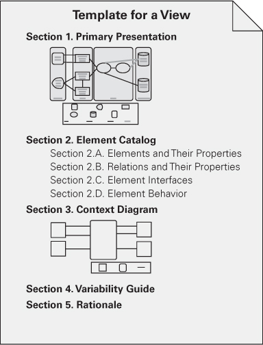
Figure 18.3. View template
No matter what the view, the documentation for a view can be placed into a standard organization consisting of these parts:
• Section 1: The Primary Presentation. The primary presentation shows the elements and relations of the view. The primary presentation should contain the information you wish to convey about the system—in the vocabulary of that view. It should certainly include the primary elements and relations but under some circumstances might not include all of them. For example, you may wish to show the elements and relations that come into play during normal operation but relegate error handling or exception processing to the supporting documentation.
The primary presentation is most often graphical. It might be a diagram you’ve drawn in an informal notation using a simple drawing tool, or it might be a diagram in a semiformal or formal notation imported from a design or modeling tool that you’re using. If your primary presentation is graphical, make sure to include a key that explains the notation. Lack of a key is the most common mistake that we see in documentation in practice.
Occasionally the primary presentation will be textual, such as a table or a list. If that text is presented according to certain stylistic rules, these rules should be stated or incorporated by reference, as the analog to the graphical notation key. Regardless of whether the primary presentation is textual instead of graphical, its role is to present a terse summary of the most important information in the view.
• Section 2: The Element Catalog. The element catalog details at least those elements depicted in the primary presentation. For instance, if a diagram shows elements A, B, and C, then the element catalog needs to explain what A, B, and C are. In addition, if elements or relations relevant to this view were omitted from the primary presentation, they should be introduced and explained in the catalog. Specific parts of the catalog include the following:
• Elements and their properties. This section names each element in the view and lists the properties of that element. Each view introduced in Chapter 1 listed a set of suggested properties associated with that view. For example, elements in a decomposition view might have the property of “responsibility”—an explanation of each module’s role in the system—and elements in a communicating-processes view might have timing parameters, among other things, as properties. Whether the properties are generic to the view chosen or the architect has introduced new ones, this is where they are documented and given values.
• Relations and their properties. Each view has specific relation types that it depicts among the elements in that view. Mostly, these relations are shown in the primary presentation. However, if the primary presentation does not show all the relations or if there are exceptions to what is depicted in the primary presentation, this is the place to record that information.
• Element interfaces. This section documents element interfaces.
• Element behavior. This section documents element behavior that is not obvious from the primary presentation.
• Section 3: Context Diagram. A context diagram shows how the system or portion of the system depicted in this view relates to its environment. The purpose of a context diagram is to depict the scope of a view. Here “context” means an environment with which the part of the system interacts. Entities in the environment may be humans, other computer systems, or physical objects, such as sensors or controlled devices.
• Section 4: Variability Guide. A variability guide shows how to exercise any variation points that are a part of the architecture shown in this view.
• Section 5: Rationale. Rationale explains why the design reflected in the view came to be. The goal of this section is to explain why the design is as it is and to provide a convincing argument that it is sound. The choice of a pattern in this view should be justified here by describing the architectural problem that the chosen pattern solves and the rationale for choosing it over another.
Documenting Information Beyond Views
As shown in Figure 18.4, documentation beyond views can be divided into two parts:
1. Overview of the architecture documentation. This tells how the documentation is laid out and organized so that a stakeholder of the architecture can find the information he or she needs efficiently and reliably.
2. Information about the architecture. Here, the information that remains to be captured beyond the views themselves is a short system overview to ground any reader as to the purpose of the system and the way the views are related to one another, an overview of and rationale behind system-wide design approaches, a list of elements and where they appear, and a glossary and an acronym list for the entire architecture.
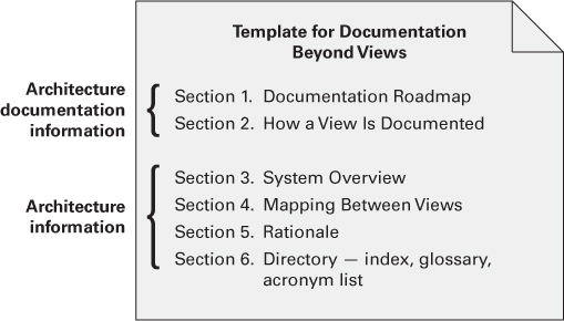
Figure 18.4. Summary of documentation beyond views
Figure 18.4 summarizes our template for documentation beyond views. Documentation beyond views consists of the following sections:
• Document control information. List the issuing organization, the current version number, date of issue and status, a change history, and the procedure for submitting change requests to the document. Usually this is captured in the front matter. Change control tools can provide much of this information.
• Section 1: Documentation Roadmap. The documentation roadmap tells the reader what information is in the documentation and where to find it. A documentation map consists of four sections:
• Scope and summary. Explain the purpose of the document and briefly summarize what is covered and (if you think it will help) what is not covered. Explain the relation to other documents (such as downstream design documents or upstream system engineering documents).
• How the documentation is organized. For each section in the documentation, give a short synopsis of the information that can be found there. An alternative to this is to use an annotated table of contents. This is a table that doesn’t just list section titles and page numbers, but also gives a synopsis with each entry. It provides one-stop shopping for a reader attempting to look up a particular kind of information.
• View overview. The major part of the map describes the views that the architect has included in the package. For each view, the map gives the following information:
• The name of the view and what pattern it instantiates, if any.
• A description of the view’s element types, relation types, and property types. This lets a reader begin to understand the kind of information that is presented in the view.
• A description of language, modeling techniques, or analytical methods used in constructing the view.
• How stakeholders can use the documentation. The map follows with a section describing which stakeholders and concerns are addressed by each view; this is conveniently captured as a table. This section shows how various stakeholders might use the documentation to help address their concerns. Include short scenarios, such as “A maintainer wishes to know the units of software that are likely to be changed by a proposed modification. The maintainer consults the decomposition view to understand the responsibilities of each module in order to identify the modules likely to change. The maintainer then consults the uses view1 to see what modules use the affected modules (and thus might also have to change).” To be compliant with ISO/IEC 42010-2007, you must consider the concerns of at least users, acquirers, developers, and maintainers.
• Section 2: How a View Is Documented. This is where you explain the standard organization you’re using to document views—either the one described in this chapter or one of your own. It tells your readers how to find information in a view. If your organization has standardized on a template for a view, as it should, then you can simply refer to that standard. If you are lacking such a template, then text such as that given above describing our view template should appear in this section of your architecture documentation.
• Section 3: System Overview. This is a short prose description of the system’s function, its users, and any important background or constraints. This section provides your readers with a consistent mental model of the system and its purpose. This might be just a pointer to a concept-of-operations document.
• Section 4: Mapping Between Views. Because all the views of an architecture describe the same system, it stands to reason that any two views will have much in common. Helping a reader understand the associations between views will help that reader gain a powerful insight into how the architecture works as a unified conceptual whole.
The associations between elements across views in an architecture are, in general, many-to-many. For instance, each module may map to multiple runtime elements, and each runtime element may map to multiple modules.
View-to-view associations can be conveniently captured as tables. List the elements of the first view in some convenient lookup order. The table itself should be annotated or introduced with an explanation of the association that it depicts; that is, what the correspondence is between the elements across the two views. Examples include “is implemented by” for mapping from a component-and-connector view to a module view, “implements” for mapping from a module view to a component-and-connector view, “included in” for mapping from a decomposition view to a layered view, and many others.
• Section 5: Rationale. This section documents the architectural decisions that apply to more than one view. Prime candidates include documentation of background or organizational constraints or major requirements that led to decisions of system-wide import. The decisions about which fundamental architecture patterns to use are often described here.
• Section 6: Directory. The directory is a set of reference material that helps readers find more information quickly. It includes an index of terms, a glossary, and an acronym list.
Online Documentation, Hypertext, and Wikis
A document can be structured as linked web pages. Compared with documents written with a text-editing tool, web-oriented documents typically consist of short pages (created to fit on one screen) with a deeper structure. One page usually provides some overview information and has links to more detailed information. When done well, a web-based document is easier to use for people who just need overview information. On the other hand, it can become more difficult for people who need detail. Finding information can be more difficult in multi-page, web-based documents than in a single-file, text-based document, unless a search engine is available.
Using readily available tools, it’s possible to create a shared document that many stakeholders can contribute to. The hosting organization needs to decide what permissions it wants to give to various stakeholders; the tool used has to support the permissions policy. In the case of architecture documentation, we would want all stakeholders to comment on and add clarifying information to the architecture, but we would only want architects to be able to change the architecture or at least provide architects with a “final approval” mechanism. A special kind of shared document that is ideal for this purpose is a wiki.
Follow a Release Strategy
Your project’s development plan should specify the process for keeping the important documentation, including architecture documentation, current. The architect should plan to issue releases of the documentation to support major project milestones, which usually means far enough ahead of the milestone to give developers time to put the architecture to work. For example, the end of each iteration or sprint or incremental release could be associated with providing revised documentation to the development team.
Documenting Patterns
Architects can, and typically do, use patterns as a starting point for their design, as we have discussed in Chapter 13. These patterns might be published in existing catalogs or in an organization’s proprietary repository of standard designs, or created specifically for the problem at hand by the architect. In each of these cases, they provide a generic (that is, incomplete) solution approach that the architect will have to refine and instantiate.
First, record the fact that the given pattern is being used. Then say why this solution approach was chosen—why it is a good fit to the problem at hand. If the chosen approach comes from a pattern, this will consist essentially of showing that the problem at hand fits the problem and context of the pattern.
Using a pattern means making successive design decisions that eventually result in an architecture. These design decisions manifest themselves as newly instantiated elements and relations among them. The architect can document a snapshot of the architecture at each stage. How many stages there are depends on many things, not the least of which is the ability of readers to follow the design process in case they have to revisit it in the future.
18.7. Documenting Behavior
Documenting an architecture requires behavior documentation that complements structural views by describing how architecture elements interact with each other. Reasoning about characteristics such as a system’s potential to deadlock, a system’s ability to complete a task in the desired amount of time, or maximum memory consumption requires that the architecture description contain information about both the characteristics of individual elements as well as patterns of interaction among them—that is, how they behave with each other. In this section, we provide guidance as to what types of things you will want to document in order to reap these benefits. In our architecture view template, behavior has its own section in the element catalog.
There are two kinds of notations available for documenting behavior. The first kind of notation is called trace-oriented languages; the second is called comprehensive languages.
Traces are sequences of activities or interactions that describe the system’s response to a specific stimulus when the system is in a specific state. A trace describes a sequence of activities or interactions between structural elements of the system. Although it is conceivable to describe all possible traces to generate the equivalent of a comprehensive behavioral model, it is not the intention of trace-oriented documentation to do so. Below we describe four notations for documenting traces: use cases, sequence diagrams, communication diagrams, and activity diagrams. Although other notations are available (such as message sequence charts, timing diagrams, and the Business Process Execution Language), we have chosen these four as a representative sample of trace-oriented languages.
• Use cases describe how actors can use a system to accomplish their goals. Use cases are frequently used to capture the functional requirements for a system. UML provides a graphical notation for use case diagrams but does not say how the text of a use case should be written. The UML use case diagram can be used effectively as an overview of the actors and the behavior of a system. The use case description is textual and should contain the use case name and brief description, the actor or actors who initiate the use case (primary actors), other actors who participate in the use case (secondary actors), flow of events, alternative flows, and nonsuccess cases.
• A UML sequence diagram shows a sequence of interactions among instances of elements pulled from the structural documentation. It shows only the instances participating in the scenario being documented. A sequence diagram has two dimensions: vertical, representing time, and horizontal, representing the various instances. The interactions are arranged in time sequence from top to bottom. Figure 18.5 is an example of a sequence diagram that illustrates the basic UML notation.
Objects (i.e., element instances) have a lifeline, drawn as a vertical dashed line along the time axis. The sequence is usually started by an actor on the far left. The instances interact by sending messages, which are shown as horizontal arrows. A message can be a method or function call, an event sent through a queue, or something else. The message usually maps to a resource (operation) in the interface of the receiver instance. A filled arrowhead on a solid line represents a synchronous message, whereas the open arrowhead represents an asynchronous message. The dashed arrow is a return message. The execution occurrence bars along the lifeline indicate that the instance is processing or blocked waiting for a return.
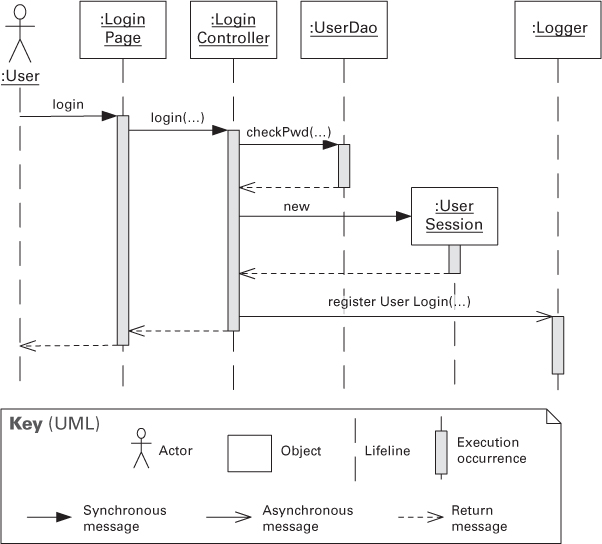
Figure 18.5. A simple example of a UML sequence diagram
• A UML communication diagram shows a graph of interacting elements and annotates each interaction with a number denoting order. Similarly to sequence diagrams, instances shown in a communication diagram are elements described in the accompanying structural documentation. Communication diagrams are useful when the task is to verify that an architecture can fulfill the functional requirements. The diagrams are not useful if the understanding of concurrent actions is important, as when conducting a performance analysis.
• UML activity diagrams are similar to flow charts. They show a business process as a sequence of steps (called actions) and include notation to express conditional branching and concurrency, as well as to show sending and receiving events. Arrows between actions indicate the flow of control. Optionally, activity diagrams can indicate the architecture element or actor performing the actions. Activity diagrams can express concurrency. A fork node (depicted as a thick bar orthogonal to the flow arrows) splits the flow into two or more concurrent flows of actions. The concurrent flows may later be synchronized into a single flow through a join node (also depicted as an orthogonal bar). The join node waits for all incoming flows to complete before proceeding. Different from sequence and communication diagrams, activity diagrams don’t show the actual operations being performed on specific objects. Activity diagrams are useful to broadly describe the steps in a specific workflow. Conditional branching (diamond symbol) allows a single diagram to represent multiple traces, although it’s not usually the intent of an activity diagram to show all possible traces or the complete behavior for the system or part of it.
In contrast to trace notations, comprehensive models show the complete behavior of structural elements. Given this type of documentation, it is possible to infer all possible paths from initial state to final state. The state machine formalism represents the behavior of architecture elements because each state is an abstraction of all possible histories that could lead to that state. State machine languages allow you to complement a structural description of the elements of the system with constraints on interactions and timed reactions to both internal and environmental stimuli.
UML state machine diagram notation is based on the statechart graphical formalism developed by David Harel for modeling reactive systems; it allows you to trace the behavior of your system, given specific inputs. A UML state machine diagram shows states represented as boxes and transitions between states represented as arrows. The state machine diagrams help to model elements of the architecture and help to illustrate their runtime interactions. Figure 18.6 is a simple example showing the states of a vehicle cruise control system.
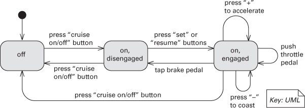
Figure 18.6. UML state machine diagram for the cruise control system of a motor vehicle
Each transition in a state machine diagram is labeled with the event causing the transition. For example, in Figure 18.6, the transitions correspond to the buttons the driver can press or driving actions that affect the cruise control system. Optionally, the transition can specify a guard condition, which is enclosed in brackets. When the event corresponding to the transition occurs, the guard condition is evaluated and the transition is only enabled if the guard is true at that time. Transitions can also have consequences, called actions or effects, indicated by a slash. When an action is noted, it indicates that the behavior following the slash will be performed when the transition occurs. The states may also specify entry and exit actions.
Other notations exist for describing comprehensive behavior. For example, Architecture Analysis and Design Language (AADL) can be used to reason about runtime behavior. Specification and Description Language (SDL) is used in telephony.
18.8. Architecture Documentation and Quality Attributes
If architecture is largely about the achievement of quality attributes and if one of the main uses of architecture documentation is to serve as a basis for analysis (to make sure the architecture will achieve its required quality attributes), where do quality attributes show up in the documentation? Short of a full-fledged quality view (see page 340), there are five major ways:
1. Any major design approach (such as an architecture pattern) will have quality attribute properties associated with it. Client-server is good for scalability, layering is good for portability, an information-hiding-based decomposition is good for modifiability, services are good for interoperability, and so forth. Explaining the choice of approach is likely to include a discussion about the satisfaction of quality attribute requirements and tradeoffs incurred. Look for the place in the documentation where such an explanation occurs. In our approach, we call that rationale.
2. Individual architectural elements that provide a service often have quality attribute bounds assigned to them. Consumers of the services need to know how fast, secure, or reliable those services are. These quality attribute bounds are defined in the interface documentation for the elements, sometimes in the form of a service-level agreement. Or they may simply be recorded as properties that the elements exhibit.
3. Quality attributes often impart a “language” of things that you would look for. Security involves security levels, authenticated users, audit trails, firewalls, and the like. Performance brings to mind buffer capacities, deadlines, periods, event rates and distributions, clocks and timers, and so on. Availability conjures up mean time between failure, failover mechanisms, primary and secondary functionality, critical and noncritical processes, and redundant elements. Someone fluent in the “language” of a quality attribute can search for the kinds of architectural elements (and properties of those elements) that were put in place precisely to satisfy that quality attribute requirement.
4. Architecture documentation often contains a mapping to requirements that shows how requirements (including quality attribute requirements) are satisfied. If your requirements document establishes a requirement for availability, for instance, then you should be able to look it up by name or reference in your architecture document to see the places where that requirement is satisfied.
5. Every quality attribute requirement will have a constituency of stakeholders who want to know that it is going to be satisfied. For these stakeholders, the architect should provide a special place in the documentation’s introduction that either provides what the stakeholder is looking for, or tells the stakeholder where in the document to find it. It would say something like this: “If you are a performance analyst, you should pay attention to the processes and threads and their properties (defined [here]), and their deployment on the underlying hardware platform (defined [here]).” In our documentation approach, we put this here’s-what-you’re-looking-for information in a section called the documentation roadmap.
18.9. Documenting Architectures That Change Faster Than You Can Document Them
When your web browser encounters a file type it’s never seen before, odds are that it will go to the Internet, search for and download the appropriate plug-in to handle the file, install it, and reconfigure itself to use it. Without even needing to shut down, let alone go through the code-integrate-test development cycle, the browser is able to change its own architecture by adding a new component.
Service-oriented systems that utilize dynamic service discovery and binding also exhibit these properties. More challenging systems that are highly dynamic, self-organizing, and reflective (meaning self-aware) already exist. In these cases, the identities of the components interacting with each other cannot be pinned down, let alone their interactions, in any static architecture document.
Another kind of architectural dynamism, equally challenging from a documentation perspective, is found in systems that are rebuilt and redeployed with great rapidity. Some development shops, such as those responsible for commercial websites, build and “go live” with their system many times every day.
Whether an architecture changes at runtime, or as a result of a high-frequency release-and-deploy cycle, the changes occur much faster than the documentation cycle. In either case, nobody is going to hold up things until a new architecture document is produced, reviewed, and released.
But knowing the architecture of these systems is every bit as important, and arguably more so, than for systems in the world of more traditional life cycles. Here’s what you can do if you’re an architect in a highly dynamic environment:
• Document what is true about all versions of your system. Your web browser doesn’t go out and grab just any piece of software when it needs a new plug-in; a plug-in must have specific properties and a specific interface. And it doesn’t just plug in anywhere, but in a predetermined location in the architecture. Record those invariants as you would for any architecture. This may make your documented architecture more a description of constraints or guidelines that any compliant version of the system must follow. That’s fine.
• Document the ways the architecture is allowed to change. In the previous examples, this will usually mean adding new components and replacing components with new implementations. In the Views and Beyond approach, the place to do this is called the variability guide (captured in Section 4 of our view template).
18.10. Documenting Architecture in an Agile Development Project
“Agile” refers to an approach to software development that emphasizes rapid and flexible development and de-emphasizes project and process infrastructure for their own sake. In Chapter 15 we discuss the relationships between architecture and Agile. Here we focus just on how to document architecture in an Agile environment.
The Views and Beyond and Agile philosophies agree strongly on a central point: If information isn’t needed, don’t document it. All documentation should have an intended use and audience in mind, and be produced in a way that serves both. One of the fundamental principles of technical documentation is “Write for the reader.” That means understanding who will read the documentation and how they will use it. If there is no audience, there is no need to produce the documentation.
Architecture view selection is an example of applying this principle. The Views and Beyond approach prescribes producing a view if and only if it addresses the concerns of an explicitly identified stakeholder community.
Another central idea to remember is that documentation is not a monolithic activity that holds up all other progress until it is complete. The view selection method given earlier prescribes producing the documentation in prioritized stages to satisfy the needs of the stakeholders who need it now.
When producing Views and Beyond-based architecture documentation using Agile principles, keep the following in mind:
• Adopt a template or standard organization to capture your design decisions.
• Plan to document a view if (but only if) it has a strongly identified stakeholder constituency.
• Fill in the sections of the template for a view, and for information beyond views, when (and in whatever order) the information becomes available. But only do this if writing down this information will make it easier (or cheaper or make success more likely) for someone downstream doing their job.
• Don’t worry about creating an architectural design document and then a finer-grained design document. Produce just enough design information to allow you to move on to code. Capture the design information in a format that is simple to use and simple to change—a wiki, perhaps.
• Don’t feel obliged to fill up all sections of the template, and certainly not all at once. We still suggest you define and use rich templates because they may be useful in some situations. But you can always write “N/A” for the sections for which you don’t need to record the information (perhaps because you will convey it orally).
• Agile teams sometimes make models in brief discussions by the whiteboard. When documenting a view, the primary presentation may consist of a digital picture of the whiteboard. Further information about the elements (element catalog), rationale discussion (architecture background), variability mechanisms being used (variability guide), and all else can be communicated verbally to the team—at least for now. Later on, if you find out that it’s useful to record a piece of information about an element, a context diagram, rationale for a certain design decision, or something else, the template will have the right place ready to receive it.
18.11. Summary
Writing architectural documentation is much like other types of writing. You must understand the uses to which the writing is to be put and the audience for the writing. Architectural documentation serves as a means for communication among various stakeholders, not only up the management chain and down to the developers but also across to peers.
An architecture is a complicated artifact, best expressed by focusing on particular perspectives depending on the message to be communicated. These perspectives are called views, and you must choose the views to document, must choose the notation to document these views, and must choose a set of views that is both minimal and adequate. This may involve combining various views that have a large overlap. You must document not only the structure of the architecture but also the behavior.
Once you have decided on the views, you must decide how to package the documentation. The packaging will depend on the media used for expressing the documentation. Print has different characteristics for understanding and grouping than various online media. Different online media will also have different characteristics.
The context of the project will also affect the documentation. Some of the contextual factors are the important quality attributes of the system, the rate of change of the system, and the project management strategy.
18.12. For Further Reading
Documenting Software Architectures (second edition) [Clements 10a] is a comprehensive treatment of the Views and Beyond approach. It describes a multitude of different views and notations for them. It also describes how to package the documentation into a coherent whole.
ISO/IEC/IEEE 42010:2011 (“eye-so-forty-two-ten” for short) is the ISO (and IEEE) standard [ISO 11] Systems and software engineering—Architecture description. The first edition of that standard, IEEE Std. 1471-2000, was developed by an IEEE working group drawing on experience from industry, academia, and other standards bodies between 1995 and 2000. ISO/IEC/IEEE 42010 is centered on two key ideas: a conceptual framework for architecture description and a statement of what information must be found in any ISO/IEC/IEEE 42010-compliant architecture description, using multiple viewpoints driven by stakeholders’ concerns.
Under ISO/IEC/IEEE 42010, as in the Views and Beyond approach, views have a central role in documenting software architecture. The architecture description of a system includes one or more views.
If you want to use the Views and Beyond approach to produce an ISO/IEC/IEEE 42010-compliant architecture document, you certainly can. The main additional obligation is to choose and document a set of viewpoints, identifying the stakeholders, their concerns, and the elements catalog for each view, and (to a lesser degree) address ISO/IEC/IEEE 42010’s other required information content.
AADL is an SAE standard. The SAE is an organization for engineering professionals in the aerospace, automotive, and commercial vehicle industries. The website for the AADL standard is at www.aadl.info.
SDL is a notation used in the telecom industry. It is targeted at describing the behavior of reactive and distributed systems in general and telecom systems in particular. A real-time version of SDL can be found at www.sdl-rt.org/standard/V2.2/pdf/SDL-RT.pdf.
UML 2.0 added several features specifically to allow architecture to be modeled, such as ports. It is managed by the Object Management Group and can be found at www.omg.org/spec/UML/.
18.13. Discussion Questions
1. Go to the website of your favorite open source system. On the site, look for the architectural documentation for that system. What is there? What is missing? How would this affect your ability to contribute code to this project?
2. Banks are justifiably cautious about security. Sketch the documentation you would need for an automatic teller machine (ATM) in order to reason about its security architecture.
3. Suppose your company has just purchased another company and that you have been given the task of merging a system in your company with a similar system in the other company. What views of the other system’s architecture would you like to see and why? Would you ask for the same views of both systems?
4. When would you choose to document behavior using trace models or using comprehensive models? What value do you get and what effort is required for each of them?
5. How much of a project’s budget would you devote to software architecture documentation? Why? How would you measure the cost and the benefit?
6. Antony Tang, an architect and one of the reviewers of this book, says that he has used a development view—a kind of quality view—that describes how the software should be developed in relation to the use of tools and development workflows, the use of standard library routines such as for exception handling, some coding conventions and standards, and some testing and deployment conventions. Sketch a definition of a development view.