Chapter 7. Execution Platform Components
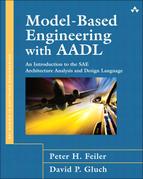
Execution platform components represent the resources of the computer system as well as elements of the external physical environment. These component categories are summarized in Table 7-1.
Table 7-1. Execution Platform Categories
The physical resources of the computer system are represented by the processor, memory, and bus categories. For example, a processor component represents a CPU chip or a processor board including operating system functionality. Similarly, a bus component represents an onboard bus such as PCI, or a network such as an Ethernet or CAN bus. It may include the functionality of a protocol. Bus components are used to physically interconnect execution platform components. A virtual processor can represent a scheduler or a virtual machine such as a Java virtual machine. A virtual bus can represent a virtual channel or a communication protocol. Memory components can represent working memory such as RAM or cache memory as well as persistent storage such as a hard drive. A device component can represent entities that interface with the external environment, such as a speed sensor or a switch actuator, or they can represent an entity of the external environment such as an engine with sensors and actuators represented as ports. Finally, we can combine these execution platform components into system components to represent computer platforms such as a board or cabinet, to physical subsystems or systems such as an engine.
7.1. Processor
A processor represents the hardware and associated software that is responsible for scheduling and executing threads. The scheduler that is part of the processor abstraction may be an interrupt handler or operating system supporting specific scheduling protocols. The processor abstraction may also include higher-level operating system services that are made accessible to the application through ports and subprogram access features. A processor may include memory for code and data as subcomponents. Alternatively, code and data may be stored in an external memory component that is connected to the processor via a bus component. The mapping of software onto processors is declared using binding properties.
7.1.1. Representations
Table 7-2 shows a type and implementation declaration for a processor including both textual and corresponding graphical representations. In this example, a single processor system with memory contained inside of the processor is shown. This memory is considered as directly accessible by the processor.
Table 7-2. A Sample Processor Textual and Graphical Representation

In the textual representation, the properties subclauses define the hardware description language (Hardware_Source_Language) and the files that contain the source code for the hardware description (Hardware_Description_Source_Text). The processor implementation declaration of Intel_Linux.impl_01 includes a single memory subcomponent HSRAM. The memory subcomponent’s type and implementation declarations are shown.
The corresponding graphical representations of type and implementation are shown to the left of the textual representation in Table 7-2. The nesting of the memory graphic (labeled HSRAM) within the processor graphic shows containment.
If the processor does not contain internal memory, it must have access to external memory components via a bus. In this case, the bus used to access the memory must either be declared as a processor subcomponent or made accessible outside the processor via a provides bus access feature, or the processor must require access to a bus external to the processor.
A processor may support a number of different communication protocols. You can model this by declaring virtual bus subcomponents to satisfy protocol requirements by port connections. Alternatively, you can specify the set of protocols supported by a processor through the Provided_Virtual_Bus_Class property by naming the respective virtual bus classifiers as the property value. The Required_Virtual_Bus_Class indicates for a port or port connection, which protocol is required.
7.1.2. Properties
The following standard processor properties can be used in a processor declaration. The example from Table 7-2 showed hardware description properties. A Scheduling_Protocol property indicates the protocol used to schedule threads. An Allowed_Dispatch_Protocol property specifies the dispatch protocols supported by the processor. We have properties that indicate the speed of the processor (Clock_Period, Assign_Time, Scaling_Factor) and the cost of context switch time between threads within the same process and between processes, and properties that identify the memory requirements of any software associated with the processor.
7.1.3. Constraints
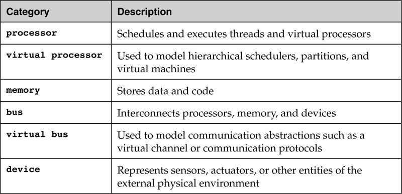
Table 7-3 summarizes the legal elements within a processor type and implementation declaration as well as the permitted components that may contain a processor.
Table 7-3. Summary of Constraints on Processor Classifier Declarations
7.2. Virtual Processor
A virtual processor represents a logical resource for scheduling and executing software. You can use it to represent a virtual machine such as the Java VM, a partition of a processor, or a scheduler in a scheduler hierarchy. You bind virtual processors to processors or to other virtual processors that eventually are bound to processors. You can also declare virtual processors as a subcomponent of a physical processor or a subcomponent of a virtual processor that is contained in a processor.
7.2.1. Representations
Example virtual processor declarations and graphical representations are shown in Table 7-4. The virtual processor graphical icon is the processor icon with dotted boundaries. There is one implementation of the virtual processor type custom shown in Table 7-4. This implementation includes a virtual bus as a subcomponent. Notice the assignment of 5 nanoseconds to the Startup_Execution_Time property in the type declaration. This value will apply to all instances of the type unless overridden for that instance.
Table 7-4. Virtual Processor Representations

Virtual processors describe how processors are divided into multiple logical resources, each with a guaranteed portion of the physical processor. For example, the ARINC 653 partition concept is represented by processes that are bound to virtual processors. The processes specify the need for space partitioning through protected address spaces, while the virtual processors assure time partitioning of the processor as resource. Virtual processors can be used to model different language runtime systems on the same processor with different application programming interfaces and functionality. In addition, virtual processors can represent multiple schedulers including hierarchical schedulers, with different scheduling protocols. For example, a virtual processor can be used to represent the Ada language runtime system with its task execution model. Similarly, a virtual processor can be used to represent an operating system thread that schedules and executes application tasks with the same period—represented by AADL threads—using a cyclic executive scheduling protocol such as a thread calling individual tasks as functions.
7.2.2. Properties
Virtual processors share properties with a processor, except for properties that describe the hardware aspects of a processor (e.g., hardware description, data movement in memory, and hardware clock properties) and those specific to a virtual processor. Virtual processor specific properties include properties that address the mapping of a virtual processor to a processor such as Allowed_Processor_Binding as well as the Startup_Execution_Time property that specifies the execution time and dispatch characteristics associated with a virtual processor. You can indicate the desired quality of service of a protocol using the Required_Connection_Quality_Of_Service property to indicate protocol service needs such as guaranteed delivery instead of prescribing a specific protocol. Similarly, the Required_Connection_Quality_Of_Service property associated with a virtual bus indicates the provided service level.
7.2.3. Constraints
Table 7-5 summarizes the legal elements within virtual processor type and implementation declarations as well as the permitted components that may contain a virtual processor.
Table 7-5. Summary of Constraints for Virtual Processor Declarations

7.3. Memory
Memory represents storage components for data and executable code. Memory components include randomly accessible physical storage (e.g., RAM, ROM), reflective memory, or permanent storage such as disks. Binding properties define the memory components in which software components are stored.
7.3.1. Representations
An example memory declaration and its graphical representation are shown in Table 7-6. In this example, a memory of the type RAM is declared with a single feature bus01 that establishes that all instances of RAM require access to the bus membus. No explicit properties for this type are declared. The type and implementation declarations for the requires bus access to bus01 are shown at the end of the listing.
Table 7-6. A Sample Memory Textual and Graphical Representation

The memory implementation RAM.compRAM declares that this implementation of the memory type RAM includes memory subcomponents HSRAM and SRAM. The subcomponents of the memory implementation RAM.compRAM are declared as implementations of a common type XRAM. An expanded memory composition can be used to model a complicated memory bank. These examples show how memory can contain other memory components and that memory must be connected to a bus unless it is enclosed in a processor.
Typically, you map two kinds of software components to memory components: processes and data components. For example, a process has memory requirements for code, local data in form of stack, and dynamic data in form of heap, expressed by the Source_Code_Size, Source_Stack_Size, and Source_Heap_Size properties. A data component represents static data that persists between thread dispatches and may be accessible by more than one thread. The Source_Data_Size property indicates the memory requirements for an instance of a given data component type (i.e., for such static data components) as well as for data communicated through ports.
Memory binding properties, as discussed in the software component sections, specify the mapping of the application components to memory components.
7.3.2. Properties
Since they have a physical runtime presence, memory components have properties such as word size and word count. Standard memory properties include
• read and write times for memory access
• memory size in terms of word size and count
• base address to indicate the physical starting address of the memory unit
The default value for memory access (Memory_Protocol) is read–write but memory access can be assigned as read only or write only.
7.3.3. Constraints
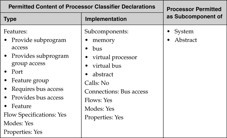
Table 7-7 summarizes the legal elements within memory type and implementation declarations as well as the permitted components that may contain a memory component. An individual memory component must be contained in a processor, declared as a subcomponent of a memory unit, or connected to a processor through a bus.
Table 7-7. Summary of Constraints on Memory Classifier Declarations
A memory component can represent memory inside of a processor or as a separate execution platform unit that is connected to the processor via a bus. Memory banks can be modeled abstractly as a single memory component, or explicitly as a composite memory unit by placing memory subcomponents inside a memory component implementation.
7.4. Bus
A bus represents the physical hardware and associated communication protocols required to support the interactions among physical components. Examples of buses are PCI bus, VME bus, CAN bus, Ethernet, and wireless networks. The role of a bus in supporting communication is defined using bus access features (that declare the need for a physical connection) and bus access connections (that declare a physical connection).
Buses are typically used to connect computer hardware components. We can also use the bus component to represent physical resources such as electrical power that is distributed to physical components and computer hardware components. We use bus access features (see Section 10.3) to indicate the need of a resource such as electrical power or the ability to contribute electrical power via a set of properties defining for modeling physical resources.
7.4.1. Representations
Table 7-8 shows a portion of an AADL textual specification and corresponding graphical representation. Included in the example are a processor type declaration for Intel_Linux and two bus type declarations for memory_bus and network_bus. The processor type declaration for Intel_Linux includes a requires bus access declaration for the bus type memory_bus and the bus type declaration memory_bus includes a requires bus access for the bus type network_bus. These required accesses are shown in the graphic on the left side of Table 7-8.
Table 7-8. A Sample Bus Specification: Textual and Graphical Representations

For example, a processor and memory require access to a bus to enable the processor to utilize the memory or to communicate with a camera via a USB bus. The need for bus access is defined in the type declarations for the processor and memory and the connections to the bus are declared explicitly within the system implementation that contains the processor, memory, and bus. Buses can be connected directly to other buses to represent inter-network communication. This is specified by requires bus access features within the bus type and explicit connection declarations between instances of these buses.
7.4.2. Properties
There are a number of standard properties that specify important bus characteristics. These include connection (e.g., Allowed_Connection_Type that specifies the categories of connections that are supported), message size (e.g., Allowed_Message_Size), transmission time (e.g., Transmission_Time), hardware source language descriptions (e.g., Hardware_Source_Language), and data movement time (e.g., Transmission_Time that specifies the time required to move a block of bytes on a bus) properties. You can use the Provided_Virtual_Bus_Class property to indicate the protocols supported by the bus type.
7.4.3. Constraints
Table 7-9 summarizes the legal elements within bus type and implementation declarations as well as the permitted components that may contain a bus component. A bus may contain virtual bus subcomponents to indicate the protocols supported by the bus as an alternative to the Provided_Virtual_Bus_Class property. You use the requires bus access to indicate that an instance of this may be connected to another bus (e.g., a local network may be connected to a backbone).
Table 7-9. Summary of Constraints on Bus Classifier Declarations

7.5. Virtual Bus
A virtual bus component represents a logical abstraction such as a virtual channel or communication protocol. Virtual buses can support connections between application software components on the same processor or across multiple processors via buses.
7.5.1. Representations
The graphical and textual representations of virtual bus type and implementation declarations are shown in Table 7-10. In the example, a single implementation of the virtual bus type high_speed_bus is shown. In addition, a virtual bus can be a subcomponent of a processor or virtual processor as shown in Table 7-4.
Table 7-10. Virtual Bus Declarations

A virtual bus can be declared as a subcomponent of a processor or bus or it can be bound to a processor or bus. Virtual buses can require other virtual buses, allowing the modeling of protocol hierarchies. Virtual buses can be used to model virtual “channels” that represent a partition of the bandwidth of a network or a bus as well as specific communication protocols and protocol stacks. The Provided_Virtual_Bus_Class property can be used to indicate that a protocol is supported. For example, a processor may indicate that it supports a certain set of protocols by referring to the virtual bus types that represent the supported protocols. Similarly, a bus may indicate the protocols it supports. A connection between ports may indicate that it requires a particular protocol using the Required_Virtual_Bus_Class property.
A protocol stack can be modeled by a single virtual bus type that indicates all the protocols of the protocol stack it makes available for application port connections through the Provided_Virtual_Bus_Class property. The same stack can also be modeled by each virtual bus type that represents a protocol indicating that it requires other protocols. The collection of Required_Virtual_Bus_Class properties in the different virtual bus types effectively represents the protocol stack hierarchy.
7.5.2. Properties
As with a virtual processor, the virtual bus abstraction shares a number of properties with its hardware counterpart. However, properties that are not common include hardware specific properties and data movement related properties. Virtual buses can specify that they require a specific protocol through the Required_Virtual_Bus_Class property. Desired virtual bus quality of service characteristics such as secure delivery or guaranteed delivery can be specified through the Required_Connection_Quality_Of_Service property. You can also declare that a virtual bus provides such characteristics using the Provided_Connection_Quality_Of_Service property.
7.5.3. Constraints
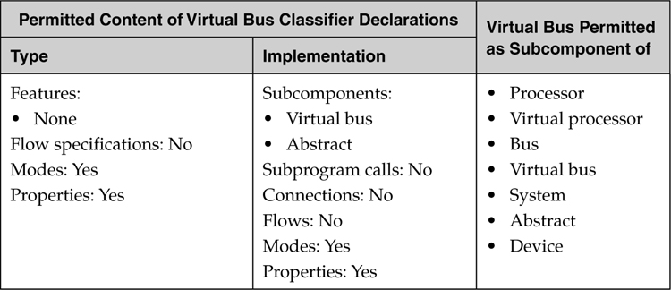
The legal elements within bus type and implementation declarations as well as the permitted components that may contain a virtual bus component are summarized in Table 7-11. Virtual buses must be contained in or bound to physical processors or buses.
Table 7-11. Summary of Constraints on Virtual Bus Classifier Declarations
7.6. Device
Device abstractions represent entities that interface with or are part of the external environment of an embedded software system, such as sensors and actuators, or engines, Global Positioning System (GPS), or cameras. Devices can represent a physical entity or a software simulation of a physical entity. A device may have its functionality fully embedded in the hardware, or it may include a device driver that must execute on a processor. The device driver and its binding can be characterized by device-specific properties to indicate that the driver is to be executed as part of the operating system. Alternatively, an explicit device driver thread can be declared to model the fact that the device driver executes separately from the OS kernel.
A device can interact with other application components through ports or subprogram access features. Device ports may represent registers or ports of a device driver. Devices interact with hardware components through bus access connections.
7.6.1. Representations
Table 7-12 shows an excerpt from an AADL model that describes a device speed_sensor interacting through a bus with a processor speed_processor. The processor executes the device driver for the speed_sensor. The requirement for bus access is specified in the type declaration for speed_sensor. Similarly, the need for bus access is declared within the processor type declaration for speed_processor. Notice that the out data port declared on the speed_sensor device type provides the rate data from the sensor. A device also can be used to represent a more complex physical element, such as an engine where the ports can represent the engine’s sensors and actuators.
Table 7-12. A Sample Device Specification: Textual and Graphical Representation

A device can have a physical connection to a processor via a bus as well as logical connections through ports to application software components. As with all logical connections among components residing on distinct execution platform elements, these logical connections must be supported by (be bound to) one or more buses that physically connect the device to the processor running the application thread. A device may require driver software that is executed on an external processor. A device’s external driver software may be considered part of a processor’s execution overhead, or it may be explicitly declared as a thread with its own execution properties.
7.6.2. Properties
Standard device properties encompass the dual software and hardware character of a device and include software-specific properties such as the names of source code files, source code language, code size, and properties for execution platform binding. Other properties are related to the execution platform (hardware) aspects of a device. These include properties specifying the files that contain the hardware description language for the device and the language used for that description. In addition, there are properties for specification of the thread properties of any device software that is executing on a processor, such as dispatch protocols and execution time-related properties.
You may want to explicitly model the implementation of device drivers. In that case, you define an abstract component implementation that contains an instance of the device driver subprogram or an instance of the device driver as thread. This classifier is then associated with the device using the Implemented_As property.
7.6.3. Constraints
Table 7-13 summarizes the legal elements within device type and implementation declarations as well as the permitted components that may contain a device. A device may support communication protocols as indicated by virtual bus subcomponents or the Provided_Virtual_Bus_Class property. A device may also contain a bus through which other components can be connected to the device, or the device may require access to an externally provided bus.
Table 7-13. Summary of Constraints on Device Classifier Declarations
