
Chapter 4
Multicast in Data Center Environments
Most of this book discusses multicast in LANs and WANs, but one of the most critical components of any organization is its data center. Understanding the nuances of how multicast functions in myriad solutions is extremely critical to the success of an organization. The goal of this chapter is to provide insight into the operation of multicast, using the most popular methods for data center implementation, including virtual port channel (VPC), Virtual Extensible LAN (VXLAN), and Application Centric Infrastructure (ACI).
Multicast in a VPC Environment
VPC is a technology that allows two Ethernet switches to appear as a single L2 entity to downstream devices, consequently minimizing the impact of blocked ports from spanning tree. Although the two VPC switches appear as a single device, they are managed independently. The benefits of VPC are that it provides Layer 2 redundancy without requiring the use of spanning-tree knobs, the convergence of a port channel is faster for link recovery, and the topology is loop free because no ports are in the spanning-tree blocking state. Figure 4-1 shows a conceptual representation of VPC.
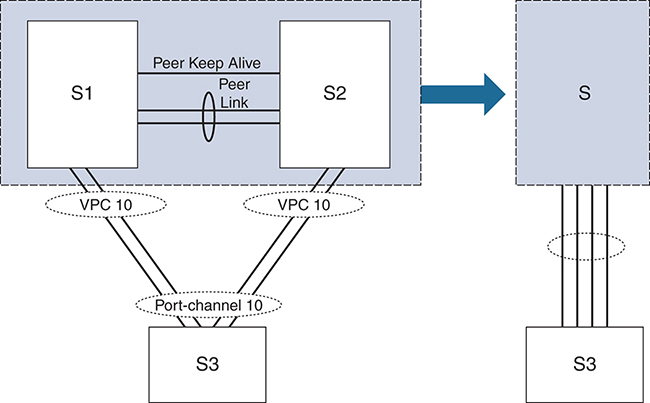
In Figure 4-1, the S1 and S2 switches are mapped to a single switch identity for all the downstream switches (S3). VPC covers combined port channel between the VPC peer device and downstream devices. VPC topology uses all port-channel links that are part of the VPC for forwarding traffic. If a link fails, local hashing of the port channel redirects the traffic to the remaining links. If one of the peer switches fails, the other peer switch has the capability to take in the traffic with minimal impact. In VPC, each peer switch runs its own control plane, and both devices work independently. (Control plane issues are localized to each peer switch.) S1 and S2 are VPC peer switches; they are connected by a special port channel known as a VPC peer link. In the peer switch configuration, one device is selected as primary, and the other device is a secondary device. The port channel (peer link) carries control traffic between two VPC switches and also carries multicast and broadcast traffic. In a few failure scenarios, unicast traffic also passes through the peer link (though that topic is beyond the scope of this book). Because of the heavy use of this link, a best practice is to use this link in dedicated rate mode proportional to southbound and northbound interface bandwidth. The VPC domain represents VPC peer devices, the VPC peer keepalive link, and all the port channels in the VPC connected to the downstream devices. The peer keepalive link is used to monitor the VPC peer switch. The periodic keepalive messages between VPC peer devices are sent via this link. No data or synchronization traffic moves over the VPC peer keepalive link. Interfaces that belong to the VPC are classified as VPC member ports. (Interfaces that are not part of VPC and have single attached receivers are called orphan ports.)
Multicast Flow over a VPC
Consider the example in Figure 4-2, in which the source is connected to the L3 network (upstream router via router A), and the receiver is connected to the VPC environment (downstream). Figure 4-2 shows the control-plane flow, which involves the following steps:

Step 1. The receiver sends an Internet Group Management Protocol (IGMP) membership join to the designated router (DR), and the flow gets hashed from the access switch connected to the core (port-channel hash). In this case, if the flow transits Switch B, then Switch B creates a snooping entry and the (*, G) mroute state with the VPC VLAN as the outgoing interface list (OIL):
SwitchB# show ip igmp groups vlan 100
IGMP Connected Group Membership for Interface "Vlan100" - 1 total entries
Type: S - Static, D - Dynamic, L - Local, T - SSM Translated
Group Address    Type Interface      Uptime    Expires    Last Reporter
239.1.1.1        D    Vlan100        00:00:31  00:04:11   10.100.100.10
SwitchB# show ip mroute
IP Multicast Routing Table for VRF "default"
(*, 239.1.1.1/32), uptime: 00:00:39, igmp ip pim
  Incoming interface: port-channel30, RPF nbr: 10.1.1.1
  Outgoing interface list: (count: 1)
    Vlan100, uptime: 00:00:39, igmp
Step 2. Switch B sends an IGMP packet to switch A, and this packet is encapsulated using Cisco Fabric Services (CFS). This creates an identical control plane state in Switch A:
SwitchB# show ip mroute
IP Multicast Routing Table for VRF "default"
(*, 239.1.1.1/32), uptime: 00:01:48, pim ip
  Incoming interface: loopback2, RPF nbr: 10.20.0.20
  Outgoing interface list: (count: 1)
    port-channel30, uptime: 00:01:48, pim


SwitchA# show ip mroute
IP Multicast Routing Table for VRF "default"
(*, 239.1.1.1/32), uptime: 00:02:02, pim ip
  Incoming interface: loopback2, RPF nbr: 10.20.0.20
  Outgoing interface list: (count: 1)
    port-channel1, uptime: 00:02:02, pim
Step 3. Now each of the two switches sends a control plane join toward the rendezvous point (RP).
Step 4. The source communicates to the first-hope router (FHR) and builds the control plane with the RP (connected through Router A upstream).
Step 5. One or both of the VPC peers receive the (S, G) join. The multicast flow state depends on the upstream routing.
Step 6. The VPC pair negotiates which peer takes on the forwarder role. CFS messages are exchanged between peers during this negotiation. The switches use the best routing metric in conjunction with VPC role as a tiebreaker. In most cases, the VPC primary becomes the forwarder because the VPC Layer 3 uses an equal-cost route toward the upstream router.
Step 7. Only the elected forwarder responds to the (S, G) state toward the source and adds the relative state changes to (S, G) entry:
SwitchA# show ip mroute
IP Multicast Routing Table for VRF "default"
(10.20.0.10/32, 239.1.1.1/32), uptime: 00:00:55, ip pim
  Incoming interface: Vlan100, RPF nbr: 10.20.0.20
  Outgoing interface list: (count: 1)
    port-channel30, uptime: 00:00:49, pim

SwitchB# show ip mroute
IP Multicast Routing Table for VRF "default"
(10.20.0.10/32, 239.1.1.1/32), uptime: 00:01:12, ip pim
  Incoming interface: Vlan100, RPF nbr: 10.20.0.20
  Outgoing interface list: (count: 0)
Switch A is the VPC primary and VPC role is used as tiebreaker for multicast forwarding path (source is connected to the upstream).
Step 8. Data flows down the source to the forwarding VPC peer.
VXLAN
VXLAN provides an overlay network to transport L2 packets on an L3 network. VXLAN uses MAC-in-UDP encapsulation, which extends Layer 2 segments. MAC-in-UDP encapsulation is illustrated in Figure 4-3.
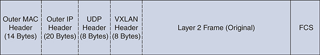
Figure 4-3 MAC-in-UDP Encapsulation in VXLAN
VTEP
The IP encapsulation of an L2 frame is accomplished with VXLAN, which uses VXLAN Tunnel Endpoints (VTEPs) to map a tenant’s end devices to VXLAN segments and to perform VXLAN encapsulation and de-encapsulation. A VTEP has two functions: It is a switch interface on the local LAN segment to support local endpoint communication via bridging, and it is also an IP interface to the transport IP network toward the remote endpoint. The VTEP IP interface identifies the VTEP on the transport IP network. The VTEPs use this IP address to encapsulate Ethernet frames as shown in Figure 4-4.
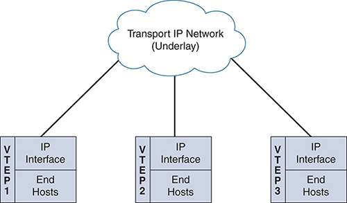
Figure 4-4 VTEP
Between the VTEPs, tunnel encapsulation provides the overlay services. Regarding VXLAN, these services are distinctively identified with a Virtual Network Identifier (VNI), which significantly expands the ability to accommodate a much larger scale of broadcast domains within the network. VNI interfaces are similar to VLANs. They keep the L2 traffic separate by using separate tagging. VNI interfaces can be aligned to network or security segmentation. Note that all VNI interfaces are associated with the same VTEP interface. Figure 4-5 is a representation of the VNI/VTEP relationship and tunnel encapsulation.
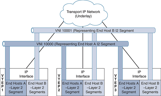
Figure 4-5 VNI/VTEP Relationship
A VTEP device holds the VXLAN forwarding table, which maps a destination MAC address to a remote VTEP IP address where the destination MAC is located, and also a local table that contains the VLAN-to-VXLAN map. As shown in Figure 4-6, the data plane is represented by the VNI interface (NVE).
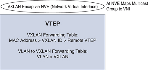
Figure 4-6 VTEP Mapping
Now that you understand the basic building blocks of VXLAN, you’re ready to look at the these VXLAN deployment types:
![]() VXLAN flood and learn
VXLAN flood and learn
![]() VXLAN with EVPN
VXLAN with EVPN
VXLAN Flood and Learn
In flood and learn mode, the source and destination frames are encapsulated with the VTEP source and destination IP addresses. The source IP address is the IP address of the encapsulating VTEP, and the destination IP address is either a multicast or unicast address of the remote VTEP that hosts the destination. VXLAN uses VTEPs to map tenants’ end devices to VXLAN segments. The communication between VTEPs depends on whether the end host address is known to the remote VTEP connected to the source; this is maintained in the VXLAN forwarding table. If the destination is known, the process leverages unicast data plane overlay communication between the VTEPs, as shown in Figure 4-7. The communication of the unicast data plane occurs when the VTEP receives an ARP reply from a connected system and knows the destination MAC address, thanks to local MAC-A-to-IP mapping to determine the IP address of the destination VTEP connected to the destination host. The original packet is encapsulated in a unicast tunnel using User Datagram Protocol (UDP), with the source IP address of the local VTEP and the destination IP address of the remote VTEP.
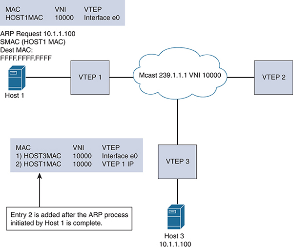
Figure 4-7 VXLAN Flood and Learn
For unknown unicast, broadcast, or multicast traffic (BUM), in VXLAN flood and learn mode, multicast is used in the underlay for learning. To illustrate this flow, say that Host 1 in Figure 4-7 sends a message to Host 3. Host 1 needs to resolve the IP/MAC binding for Host 3. Host 1 sends out an ARP request with DMAC=FFFF.FFFF.FFFF. VTEP 1 receives the ARP and verifies whether the binding is available in its local table. If it is not available, VTEP 1 sends a multidestination frame to all the member VTEPs of the corresponding VNI (for example, VNI 1000). This message is encapsulated in the multicast frame source IP of VTEP 1 and the destination of the multicast group (for example, 239.1.1.1). The VTEP members of VNI 1000 are the receivers of the multicast group. The remote VTEP 3 connected to Host 3 creates a control plane response to VTEP 1 after the multidestination frame is de-encapsulated. The multidestination traffic is flooded over the VXLAN between VTEPs to learn about the host MACs located behind the VTEPs so that subsequent traffic can be sent via unicast. This same mechanism is used for broadcast or multicast data frames that need to be sent via the overlay.
To understand the configuration better, Figure 4-8 shows a use of VXLAN.

Figure 4-8 VXLAN Flood and Learn Configuration
Let’s review the leaf configuration for VXLAN leaves. The following steps provide an overview of the configuration needed for a VXLAN leaf to flood and learn:
Step 1. Enable the relevant protocols needed for the leaf:
feature ospf
feature pim
feature nv overlay
feature vn-segment-vlan-based
Step 2. Enable the IGP for the underlay:
router ospf 1
router-id 100.100.100.1
Step 3. Enable multicast (with Anycast RP configuration at the spine):
ip pim rp-address 10.100.1.1 group-list 224.0.0.0/4
Step 4. Enable loopback 0 (used as a common VTEP IP address between two VPC peers configured at the leaf 10.50.1.1/32):
interface loopback0
 ip address 10.20.1.1/32
 ip address 10.50.1.1/32  secondary
 ip router ospf 1 area 0.0.0.0
 ip pim sparse-mode
  <.. Uplinks should be layer 3 interfaces..>
Step 5. Configure nve1 and downstream host VLANs:
interface nve1
no shutdown
source-interface loopback0
 member vni 10000 mcast-group 239.1.1.1

vlan 2901
 vn-segment 2901
Note: In flood and learn, the spine only needs to support routing paths between the leafs. The RPs (pim sparse-mode, Anycast RP distribution) need to be added to the spine configuration.
Example 4-1 shows the show commands you can use to verify that the NVE peers are using multicast.
Example 4-1 Leaf VTEP 1: show nve peers Command Output
VTEP-1# show nve peers
Interface Peer-IP          State LearnType Uptime   Router-Mac
--------- ---------------  ----- --------- -------- -----------------
nve1      10.50.1.1         Up    DP        00:05:09 n/a

VTEP-1# show nve vni
Codes: CP - Control Plane        DP - Data Plane
       UC - Unconfigured         SA - Suppress ARP

Interface VNI      Multicast-group   State Mode Type [BD/VRF]      Flags
--------- -------- ----------------- ----- ---- ------------------ -----
nve1      2901     239.1.1.1         Up    DP   L2 [2901]


VTEP-1# show ip mroute
IP Multicast Routing Table for VRF "default"

(*, 232.0.0.0/8), uptime: 5d10h, pim ip
  Incoming interface: Null, RPF nbr: 0.0.0.0, uptime: 5d10h
  Outgoing interface list: (count: 0)

(*, 239.1.1.1/32), uptime: 00:05:18, nve ip pim
  Incoming interface: Ethernet1/58, RPF nbr: 10.19.9.2, uptime: 00:05:18
  Outgoing interface list: (count: 1)
    nve1, uptime: 00:05:18, nve

(10.11.2.2/32, 239.1.1.1/32), uptime: 00:05:18, nve ip mrib pim
  Incoming interface: loopback0, RPF nbr: 10.11.2.2, uptime: 00:05:18
  Outgoing interface list: (count: 1)
    Ethernet1/58, uptime: 00:02:34, pim

(10.50.1.1/32, 239.1.1.1/32), uptime: 00:02:26, ip mrib pim nve
  Incoming interface: Ethernet1/59, RPF nbr: 10.19.10.2, uptime: 00:02:21
  Outgoing interface list: (count: 1)
    nve1, uptime: 00:02:26, nve
VXLAN with EVPN
Using Border Gateway Protocol (BGP) and Ethernet virtual private networks (EVPNs) with VXLAN reduces the problems related to learning via flooding (which is applicable in scalable environments). VXLAN optimizes learning of MAC addresses of all hosts in the VXLAN fabric without flood behavior. BGP is a standardized protocol for Network Layer Reachability Information (NLRI) to exchange host-to-host reachability and learning within the fabric. BGP NLRI provides complete visibility of all the MAC and IP address combinations of the hosts behind the VTEP in order to complete VXLAN fabric connectivity by providing the MAC/IP info to all VTEPs. The EVPN extensions that are part of BGP (or Multiprotocol BGP MBGP) add enough information within these to standardize the control plane for communication. Through integrated routing and switching, BGP EVPN facilitates transport for both L2 and L3, using known workload addresses present within the VXLAN network. This is particularly useful in multitenant environments as MAC address and IP information can be separated by BGP NLRI for individual tenants. Figure 4-9 shows this VXLAN capability.
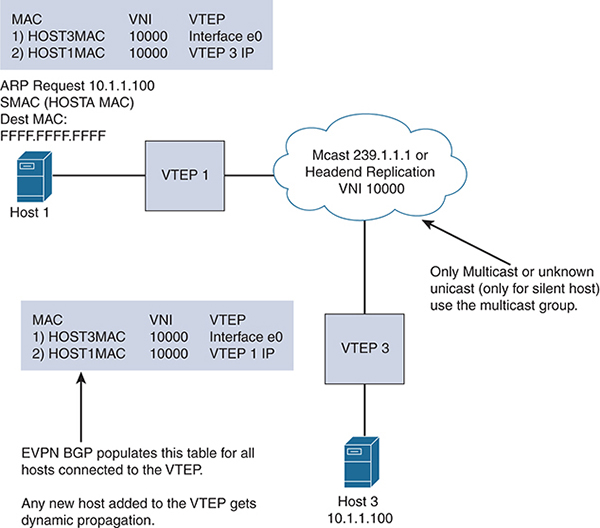
Figure 4-9 VXLAN with an EVPN
The EVPN address family allows the host MAC, IP, network, Virtual Route Forwarding (VRF), and VTEP information to be carried over MBGP. In this way, within the fabric, the VTEP learns about hosts connected using BGP EVPN. BGP EVPN does not eliminate the need for flooding for BUM traffic, but unknown unicast is eliminated (sparing silent hosts). However, broadcast and multicast data communication between the hosts still needs to be transported. The transportation is implemented by multicast underlay, which is similar to flood and learn, but the multicast traffic is optimized because all hosts’ IP/MAC addresses are learned via BGP EVPN. The only exception is silent hosts. In BGP EVPN or flood and learn mode, the multicast deployments are either Any-Source Multicast (ASM) (using Anycast) or bidirectional (with a phantom RP). With ASM, the multicast design uses the spine as the RP for the underlay traffic traversal. Multicast implementation involves one group to manage a set of VNIs (grouped under a category that is tied to multitenancy, user groups, and so on). This reduces the multicast state table in the underlay.
You can also have each VNI tied to a separate multicast group; this is adequate for a small deployment, but you should not consider it for larger deployments that have scale constraints due to the number of multicast group entries mapped with each VNI. VXLAN supports up to 16 million logical L2 segments, using the 24-bit VNID field in the header. With one-to-one mapping between VXLAN segments and IP Multicast groups, an increase in the number of VXLAN segments causes a parallel increase in the required multicast address space and some forwarding states on the core network devices. Packets forwarded to the multicast group for one tenant are sent to the VTEPs of other tenants that are sharing the same multicast group. This communication is inefficient utilization of multicast data plane resources. Therefore, the solution is a trade-off between control plane scalability and data plane efficiency.
To understand the configuration of VXLAN with BGP EVPN, let’s review the use case of BGP EVPN with a multicast underlay configuration. The diagram in Figure 4-10 illustrates eBGP established between spine and leaf, using Nexus 9000 devices.
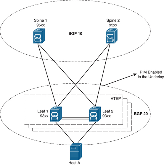
Figure 4-10 VXLAN with eBGP Between Leaf and Spine
Step 1. Enable the EVPN control plane:
nv overlay evpn
Step 2. Enable the relevant protocols needed for the spine:
feature bgp
feature pim
(In this case, BGP is used for the underlay and overlay.)
Step 3. Configure loopback for the local VTEP IP, the BGP peer relationship (loopback 0), and anycast (loopback 1):
interface loopback0
  ip address 10.10.1.1/32
  ip pim sparse-mode
interface loopback1
  ip address 10.100.1.1/32
  ip pim sparse-mode
Step 4. Configure Anycast RP:
ip pim rp-address 10.100.1.1 group-list 225.0.0.0/8
ip pim rp-candidate loopback1 group-list 225.0.0.0/8
ip pim log-neighbor-changes
ip pim anycast-rp 10.100.1.1 10.10.1.1
ip pim anycast-rp 100.1.1.1 10.20.1.1
Step 5. Configure the route map used by eBGP at the spine:
route-map permitANY permit 10
  set ip next-hop unchanged
Note: Interfaces between the spine and leaf are Layer 3 interfaces with PIM sparse mode. If the underlay is BGP, use the interfaces to establish peer relationships.
Step 6. Configure the BGP overlay for the EVPN address family:
router bgp 10
  router-id 10.10.1.1
  address-family l2vpn evpn
    nexthop route-map permitANY
    retain route-target all
  neighbor 10.30.1.1 remote-as 20
    update-source loopback0
    ebgp-multihop 3
    address-family l2vpn evpn
      disable-peer-as-check
      send-community extended
      route-map permitANY out
  neighbor 10.40.1.1 remote-as 20
    update-source loopback0
    ebgp-multihop 3
    address-family l2vpn evpn
      disable-peer-as-check
      send-community extended
      route-map permitANY out
Step 7. Specify the BGP underlay configurations (with the direct IP address of the interface between the spine and leaf):
neighbor 172.16.1.2 remote-as 20
    address-family ipv4 unicast
      allowas-in
disable-peer-as-check
<..>
Leaf Configuration
The leaf configuration with EVPN VXLAN is as follows:
Note: Interfaces between the spine and leaf are Layer 3 interfaces with PIM sparse mode. If the underlay is BGP, use the interfaces to establish peer relationships.
Step 1. Enable the EVPN control plane:
nv overlay evpn
Step 2. Enable the relevant features:
feature bgp
feature pim
feature interface-vlan
feature dhcp
feature vn-segment-vlan-based
feature nv overlay
fabric forwarding anycast-gateway-mac 0000.2222.3333
Step 3. Enable PIM RP:
ip pim rp-address 10.100.1.1 group-list 225.0.0.0/8
Step 4. Configure the loopback for BGP and configure the loopback for the local VTEP IP:
interface loopback0
  ip address 10.30.1.1/32
  ip address 10.30.50.1/32 secondary

  ip pim sparse-mode
Because the leaf device has a VPC configuration, use the same IP address (secondary) for both the VPC peers, including the NVE connection source.
Step 5. Create the VRF overlay VLAN and configure the vn-segment:
vlan 101
  vn-segment 1001
Step 6. Configure the VRF overlay VLAN/SVI for the VRF:
interface Vlan101
  no shutdown
  vrf member vxlan-red
Step 7. Create the VLAN and provide mapping to VXLAN (with the user VLAN segment to which you have downstream hosts):
vlan 2901
  vn-segment 2901
Step 8. Create the VRF and configure the VNI:
vrf context vxlan-red
  vni 1001
  rd auto
  address-family ipv4 unicast
    route-target import 65535:100 evpn
    route-target export 65535:100 evpn
    route-target import 65535:100
    route-target export 65535:100
Step 9. Create the server-facing SVI and enable distributed anycast-gateway:
interface Vlan2901
  no shutdown
  vrf member vxlan-red
  ip address 192.168.4.1/24
  fabric forwarding mode anycast-gateway
Step 10. Create the NVE interface 239.1.1.1:
interface nve1
  no shutdown
  source-interface loopback1
  host-reachability protocol bgp
  member vni 10001 associate-vrf
  member vni 2901
    suppress-arp
    mcast-group 239.1.1.1
Step 11. Configure BGP for the underlay and overlay (EVPN):
router bgp 20
router-id 10.30.1.1
  neighbor 10.10.1.1 remote-as 10
    update-source loopback0
    ebgp-multihop 3
      allowas-in
      send-community extended
    address-family l2vpn evpn
      allowas-in
      send-community extended
  neighbor 10.20.1.1 remote-as 100
    update-source loopback0
    ebgp-multihop 3
      allowas-in
      send-community extended
    address-family l2vpn evpn
      allowas-in
      send-community extended
  vrf vxlan-red
      advertise l2vpn evpn
<.. single tenant VRF Red..>
evpn
  vni 2901 l2
    rd auto
    route-target import auto
    route-target export auto
 <.. add other user VNIs..>
Then view the nve peers using the show nve peers command:
show nve peers
9396-B# show nve peers
Interface  Peer-IP          Peer-State
---------  ---------------  ----------
nve1       10.30.1.1         Up
To verify the status of the VNI use the show nve vni command:
show nve vni
9396-B# show nve vni
Codes: CP - Control Plane        DP - Data Plane
       UC - Unconfigured         SA - Suppress ARP

Interface VNI     Multicast-group   State Mode Type [BD/VRF]      Flags
--------- ------- ----------------- ----- ---- ------------------ -----
nve1      1001    n/a               Up    CP   L3   [vxlan-red]
nve1      2901    239.1.1.1         Up    CP   L2   [2901]        SA
The control plane for the VNI is built and can be viewed by show ip mroute at the VTEP (leaf), see the highlighted flags to shows the nve control state:
VTEP-1# sh ip mroute
IP Multicast Routing Table for VRF "default"

(*, 232.0.0.0/8), uptime: 5d10h, pim ip
  Incoming interface: Null, RPF nbr: 0.0.0.0, uptime: 5d10h
  Outgoing interface list: (count: 0)

(*, 239.1.1.1/32), uptime: 00:05:18, nve ip pim
  Incoming interface: Ethernet1/58, RPF nbr: 10.19.9.2, uptime: 00:05:18
  Outgoing interface list: (count: 1)
    nve1, uptime: 00:05:18, nve

(10.11.2.2/32, 239.1.1.1/32), uptime: 00:05:18, nve ip mrib pim
  Incoming interface: loopback0, RPF nbr: 10.11.2.2, uptime: 00:05:18
  Outgoing interface list: (count: 1)
    Ethernet1/58, uptime: 00:02:34, pim

(10.50.1.1/32, 239.1.1.1/32), uptime: 00:02:26, ip mrib pim nve
  Incoming interface: Ethernet1/59, RPF nbr: 10.19.10.2, uptime: 00:02:21
  Outgoing interface list: (count: 1)
    nve1, uptime: 00:02:26, nve
Ingress Replication
In this case, the BUM traffic is not sent via the multicast underlay. Instead, data packets are replicated by the ingress VTEP to other neighboring VTEPs that are part of the same VNI. The resources the ingress VTEP needs to allocate for BUM traffic are tied to the number of VTEPs associated with the VNI in the fabric. The ingress replication method can also be applied to BGP EVPN and VXLAN flood and learn, as shown in Example 4-2 (using the topology from Figure 4-10).
Example 4-2 Leaf Configuration for nve1 for Ingress Replication
interface nve1
  no shutdown
  source-interface loopback0
  host-reachability protocol bgp
  member vni 2901
    suppress-arp
    ingress-replication protocol static
      peer-ip 10.50.1.1
  member vni 900001 associate-vrf
Example 4-3 shows the command to verify ingress replication.
Example 4-3 Verifying Ingress Replication
VTEP-1# show nve vni ingress-replication
Interface VNI      Replication List  Source  Up Time
--------- -------- ----------------- ------- -------

nve1      2901     10.50.1.1          CLI     00:00:33
VTEP-1#
The spine and leaf need not have multicast configuration with ingress replication. Leaf IP address 10.50.1.1 (loopback 0 for remote VTEP identification) is mentioned in this configuration. The example shows only two VTEPs participating in the fabric. The ingress replication IP address is equal to the total number of leafs in the fabric and must be replicated to all the VNI segments in the leaf.
Host-to-Host Multicast Communication in VXLAN
In VXLAN, there are two types of multicast host-to-host communication:
![]() Layer 2 communication within the boundary of the VNI
Layer 2 communication within the boundary of the VNI
![]() Layer 3 multicast communication
Layer 3 multicast communication
Layer 2 Communication Within the Boundary of the VNI
Enabling IGMP snooping helps achieve communication to hosts in the VNI that are interested in multicast traffic. With standard IGMP snooping, the VTEP interface is added to the outgoing interface list for multicast traffic. Then, even if no receiver is connected to the VTEP, the VTEP receives the traffic and drops it. The way to optimize this behavior for only the VTEP with multicast receivers in the L2 VNI is by adding the configuration shown in Example 4-4 (under the bridge domain).
Example 4-4 Configuration to Optimize IGMP Snooping for VLXAN
VTEP-2(config)# ip igmp snooping vxlan
VTEP-2 (config)# int vlan 01
VTEP-2 (config-if)# ip igmp snooping disable-nve-static-router-port
VTEP-2 (config)#
You can configure ip igmp snooping disable-nve-static-router-port globally or per VLAN to learn snooping states dynamically, as show in Figure 4-11.
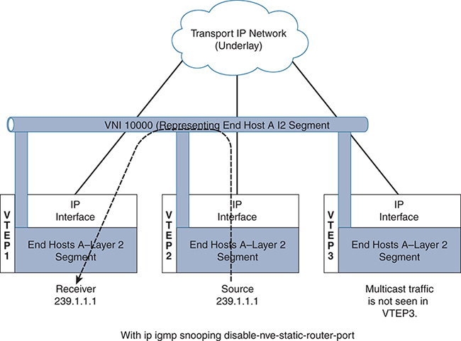
Figure 4-11 L2 Communication Within the Boundary of the VNI
Using this command, the VTEP interface to the multicast group is added to the Layer 2 outgoing interface, based on the availability of the receiver. In Figure 4-11 the multicast source is connected to VTEP2. The traffic does not get flooded to all the VTEPs where the VNI has an instance. Instead, communication is optimized between VTEP2 and VTEP1, and VTEP 3 does not get the traffic because no receiver is connected to VTEP3 for the multicast traffic 239.1.1.1.
Layer 3 Multicast Communication
The routed multicast capability over VXLAN fabric is achieved by extending the bridge domain over VXLAN to the edge router. A per-tenant pairing needs to be configured to establish a Protocol Independent Multicast (PIM) relationship within the L3 environments. Unfortunately, this per-tenant peering is not efficient.
Figure 4-12 shows a centralized model of a multicast control plane for a VXLAN fabric. The VXLAN fabric leverages an external router. This method is similar to using Layer 2 multicast in a given bridge domain sent to an external router. All bridge domain instances are present in the router. The default gateway for the VXLAN is still through the unicast distributed anycast gateways. The designated router for PIM is at the external router, outside the VXLAN fabric. Incoming packets will need to pass the Reverse Path Forwarding (RPF) checks on the external router. The external router knows all the sources or receivers in the fabric and is the conduit to exchange unicast RIB information with the L3 environment outside the fabric. However, with this approach, you need a dedicated external router infrastructure to support multicast. A future VXLAN solution with multicast may evolve with more distributed approaches for Layer 3 deployment.
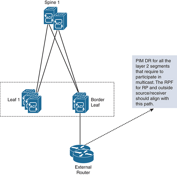
Figure 4-12 VXLAN Fabric
Multicast in ACI Data Center Networks
Application Centric Infrastructure (ACI) is a software-defined networking (SDN) solution developed by Cisco to run and control data center networks, with a special emphasis on multitenancy. ACI uses a spine/leaf topology, much like the VXLAN topology shown in the previous section. The major difference between a typical VXLAN fabric and ACI is that the underlying fabric is constructed and deployed by the central controller, the Application Policy Infrastructure Controller (APIC).
The switches in the fabric are the same Nexus 9300s, the fabric still uses IS-IS and VXLAN for provisioning, and each switch performs forwarding in the same independent manner. The APIC is merely a configuration and collection entity that uses specific constructs to create isolated networks that overlay on the VXLAN fabric, much as an architect designs. Segmentation is derived from common policy elements and is based on either application requirements (in which case it’s called application-centric), or network requirements (in which case it’s called network-centric). IP Multicast is then deployed within these overlay segments. Figure 4-13 depicts an ACI fabric topology with external L3 routing.
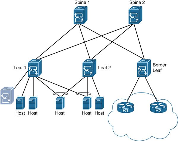
Figure 4-13 ACI Fabric with External L3 Routing
Each of the leaf and border leaf switches in the ACI topology is acting as a VTEP. Thus, many of the same rules for multicast routing over VXLAN apply. The major differences in an ACI deployment are related to the way the network handles network overlay elements. These elements include endpoint groups (EPGs), bridge domains (BDs), policies, and Virtual Route Forwarding (VRF) instances. These elements allow ACI to isolate tenants, networks, and applications within the underlying VXLAN fabric. All these elements are configured with the APIC, like the one shown in Figure 4-13.
Regardless of the virtual network topologies overlaid on the fabric, ACI uses a specific forwarding model for all multidestination traffic that is a little unique. All multidestination traffic in an ACI fabric is encapsulated in a IP Multicast packet. These packets then follow a forwarding tag (FTAG) tree, which is built between leafs and fabric spines so that traffic is load balanced over all available bandwidth. The idea is that if the leaf must send all traffic north, regardless of its east–west or north–south path, load splitting traffic between the spines improves the overall efficiency of the fabric. FTAGs are built into the MAC address of each packet that uses the tree. The spine switches manage the tree and then forward the packets to any VTEPs in the tree that need the packet. Each FTAG has one FTAG tree associated with it. Between any two switches, only one link forwards per FTAG. Because there are multiple FTAGs, parallel links are used, with each FTAG choosing a different link for forwarding. A larger number of FTAG trees in the fabric means better load balancing potential. The ACI fabric supports up to 12 FTAGs. Figure 4-14 depicts the FTAG tunneling matrix for a two-spine, three-leaf fabric.
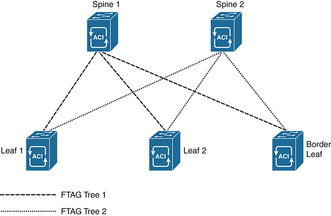
Figure 4-14 FTAG Tree Forwarding
ACI Fabrics and Overlay Elements
In order to understand the unique differences of a multicast implementation, it is helpful to quickly review the ACI fabric and how traffic is driven by policy across the network. This is not intended to be a thorough review of ACI technology but rather an introduction to the elements relevant to moving multicast across the ACI fabric. For information about the configuration of ACI, the APIC, and design elements, refer to the ACI configuration guides available at www.cisco.com.
ACI uses a database of elements to construct a network overlay configuration that resides on top of the VXLAN infrastructure. These elements do not necessarily correspond to traditional network design elements. For example, the APIC can be configured to use VPCs for physical packet transport across the fabric. In this case, a VPC is a fabric construct used to determine packet flow between leaf switches and connected hosts.
A VLAN is an example of a traditional network element that is used differently in ACI than in conventional networks. The APIC uses VLAN numbers to segment traffic inbound or outbound from the fabric, but VLAN tagging isn’t necessary to create segmentation within the fabric, nor are VLANs required for forwarding between segments.
Instead, ACI segregates traffic based on VRFs, EPGs, and bridge domains. An EPG is quite simply a defined collection of interfaces (physical access ports or virtual access ports, like those of a virtual server). Ports are gathered into EPGs so that policy is applied across all the ports in a similar manner. Using default configurations, IP hosts within an EPG are able to communicate with each other (which means there is an explicit default trust policy between hosts inside an EPG).
A bridge domain is a Layer 2 construct, similar in purpose to a VLAN, but it does not use a VLAN tag. The purpose of a bridge domain is to provide logical segmentation at Layer 2 within the EPG. An ACI VRF is essentially the same as any Layer 3 VRF and serves the same purpose as the bridge domain except at Layer 3. Thus, loopback addresses, IP routing, and L3 functions for a specific purpose are configured under a VRF.
An EPG can have multiple bridge domains and VRFs, but it is not a requirement as there is a default bridge domain and a default VRF for each EPG. There must be one of each to fully operate at each layer (Layers 2 and 3). Hosts connected to ports in different EPGs cannot, by default, communicate with each other. Instead, specific policies must be applied to allow inter-host communication between EPGs. Policies are unidirectional forwarding rules that allow specific traffic, like a firewall whitelist. This includes potential Layer 3 hosts, such as routers and firewalls, that are outside the ACI fabric. For this purpose, a specific type of policy, an L3 Out policy, is provided to route IP traffic beyond the fabric. Figure 4-15 shows a visualization of these elements overlaid on the fabric from Figure 4-13.
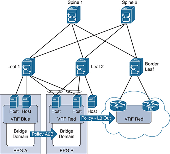
In this network design, two hosts are added to EPG A, and two hosts are added to EPG B. A fifth host is a bare metal server with no EPG assignment. Each EPG has one bridge domain and one VRF. In order for the hosts in EPG A to communicate with the hosts in EPG B, a specific policy—in this case Policy A2B—must explicitly allow it. Without a policy in the return direction, the hosts in EPG B cannot respond to EPG A. In addition, a host without an EPG is isolated from the other hosts in this diagram, including the routers (R1 and R2) that are connected to the border leaf switch. Finally, an L3 Out policy is applied to EPG B to allow IP traffic to move toward routers R1 and R2 and outside the fabric.
Note: The diagram depicts the policies in this way to make clear how ACI forwarding occurs. This is not a recommended ACI design. An in-depth discussion of ACI is beyond the scope of this text. For more information on ACI operations and configurations, please refer to ACI design guides available at www.cisco.com.
Layer 2 IGMP Snooping in ACI
ACI supports IGMP snooping by enabling an IGMP router function in software. The IGMP router function is enabled first within a bridge domain and is used to discover EPG ports that have attached hosts that are multicast clients. ACI uses the port information obtained through IGMP snooping to reduce bandwidth consumption in a multi-access bridge domain environment. If the leaf switch knows where the clients are located, there is no need to flood multicast flows across the entire bridge domain. Instead, only leaf ports with attached subscribers receive multicast flow packets for a given flow. IGMP snooping is enabled on each bridge domain by default.
When IGMP snooping is enabled, the leaf switch snoops the IGMP membership reports and leave messages as they enter the fabric from attached hosts. The leaf switch records the group subscriptions and then forwards them to the IGMP router function—only if L3 processing is required. Figure 4-16 shows the IGMP router function and IGMP snooping functions both enabled on an ACI leaf switch.

Figure 4-16 ACI IGMP Snooping
When VRFs are deployed in the overlay, IGMP snooping can also be configured on the VRF. If no VRF is configured, the default VRF (which is enabled with IGMP snooping) is used for all bridge domains. The VRF is the recommended location to control IGMP snooping when necessary. Do not disable snooping on the bridge domains so that multicast efficiency is still achieved for flows that are intra-bridge domain. This also prevents overflooding of multicast packets in those scenarios.
ACI supports IGMP snooping for all three versions of IGMP and the corresponding unique messages of each version. Additional IGMP snooping features available on within an ACI overlay include the following:
![]() Source filtering that allows forwarding of multicast packets based on destination and source IP addresses
Source filtering that allows forwarding of multicast packets based on destination and source IP addresses
![]() Multicast forwarding based on IP addresses rather than the MAC address
Multicast forwarding based on IP addresses rather than the MAC address
![]() Multicast forwarding based on the MAC address
Multicast forwarding based on the MAC address
For more information on these specific features, see the ACI Layer 2 IGMP snooping configuration guide at www.cisco.com.
The following section takes a closer look at how ACI handles multicast flows within a Layer 3 overlay network.
Layer 3 Multicast in ACI
ACI is an advanced data center networking platform that uses SDN. ACI, therefore, supports both Layer 2 and Layer 3 multicast configurations within the configurable virtual network overlays. PIM is supported in these constructs; however, it is important to understand the following:
![]() PIM-enabled interfaces: The border leaf switches run the full PIM protocol. This allows the ACI fabric to peer with other PIM neighbors outside the fabric.
PIM-enabled interfaces: The border leaf switches run the full PIM protocol. This allows the ACI fabric to peer with other PIM neighbors outside the fabric.
![]() Passive mode PIM-enabled interfaces: The PIM-enabled interfaces do not peer with any PIM router outside the fabric. This is configured on all non-border leaf interfaces.
Passive mode PIM-enabled interfaces: The PIM-enabled interfaces do not peer with any PIM router outside the fabric. This is configured on all non-border leaf interfaces.
![]() The fabric interface: This interface is used within the fabric for multicast routing. This interface is a software representation of a segment/node in ACI fabric for multicast routing. The interface is similar to a tunnel interface with the destination being GIPo (Group IP Outer Address). VRF GIPo is allocated implicitly based on the configuration of the APIC. There is one GIPo for the VRF and one GIPo for every bridge domain under that VRF. Each interface is tied to a separate multitenant domain (VRF) in the same node. Within the fabric, if the border leaf has an outgoing interface for multicast group 239.1.1.1, the fabric interface is tied to the VRFs. This is accomplished by using a unique loopback address on each border leaf on each VRF that enables multicast routing. Figure 4-17 gives a quick depiction of how the logical fabric interfaces are viewed by the leaf switches.
The fabric interface: This interface is used within the fabric for multicast routing. This interface is a software representation of a segment/node in ACI fabric for multicast routing. The interface is similar to a tunnel interface with the destination being GIPo (Group IP Outer Address). VRF GIPo is allocated implicitly based on the configuration of the APIC. There is one GIPo for the VRF and one GIPo for every bridge domain under that VRF. Each interface is tied to a separate multitenant domain (VRF) in the same node. Within the fabric, if the border leaf has an outgoing interface for multicast group 239.1.1.1, the fabric interface is tied to the VRFs. This is accomplished by using a unique loopback address on each border leaf on each VRF that enables multicast routing. Figure 4-17 gives a quick depiction of how the logical fabric interfaces are viewed by the leaf switches.
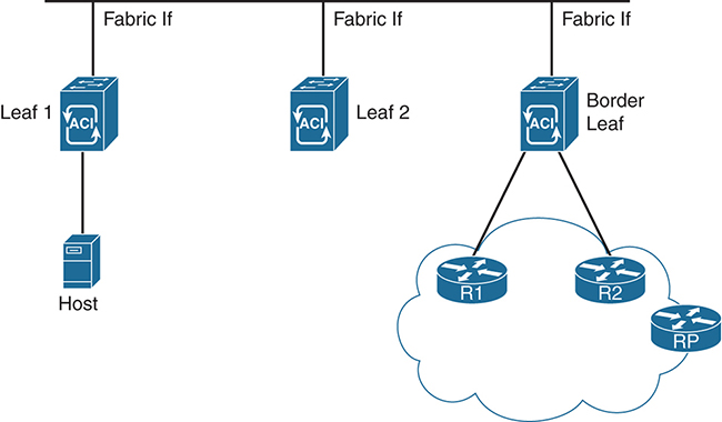
To enable multicast in a fabric, you need to configure a VRF, an L3 Out (for the respective VRF), and a bridge domain. The bridge domains must be enabled to participate in multicast; otherwise, even if the VRF is configured with multicast, the bridge domain is not seen. Multicast-enabled pervasive bridge domains are stubs for multicast routing. The Switched Virtual Interface (SVI) of the bridge domain is considered the DR of anything that is connected southbound.
Note: In data center networking, the traffic entering and exiting the data center is typically referred to as north–south traffic, while traffic that spans the data center is called east–west traffic. In the explanation above, southbound refers to traffic entering the data center and moving toward the hosts (that is, moving south).
It is very important to have all three logical constructs enabled for multicast traffic to flow. While configuring the L3 Out port, use individual ports or subinterfaces (the only interfaces that currently support multicast). Because SVIs are not supported by multicast PIM, these interfaces cannot be enabled in any L3 Out with VPC configuration.
The border leaf configuration for multicast is key because the outgoing interface list (OIF) from the fabric within a VRF points to the border leaf. The border leaf is also the designated forwarder for attracting the traffic from the external network. To avoid duplication of multicast traffic within the fabric, the border leafs elect the responsible border leaf for a multicast group to attract the traffic into the fabric on behalf of the receivers. This is tied to a VRF tenant election on the border leaf for the multicast group. The designated border leaf forwarder for group information is exchanged among all the border leafs.
Figure 4-18 shows a sample network design using these principles. In ACI, only the border leaf switches run a full PIM process. Leaf switches that are not borders run PIM in a type of passive mode, encompassing any multicast-enabled interfaces. These switches do not peer with any other PIM routers. Border leaf switches are configured to peer with the PIM routers, R1 and R2, connected to them over L3 Outs. If additional border switches are configured on this network, there is also a PIM relationship between them. RP functions in this network are located in the external L3 domain but could be moved closer to the ACI fabric.
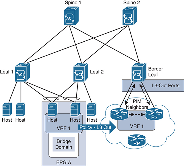
Figure 4-18 ACI Multicast with L3 Out Policy
What is passive mode PIM on the non-border-leaf switches? For ACI, Cisco has developed a new passive probe that only sends PIM hello packets but does not process received hellos. This passive mode runs on all non-border-leaf fabric interfaces and on any pervasive bridge domain SVIs. The switch does not expect to see PIM neighbors on these interfaces, and no relationship is required to add them to the PIM forwarding tree. Remember that it is assumed that all non-local PIM destinations for a flow must first flow through the spine switches. This simplifies the tree-building process and makes PIM more efficient on the leaf switches.
However, on fabric interfaces, PIM receives and processes the following PIM packets:
![]() PIM hellos: These are used to track the active border leaf list on the fabric interface and on the pervasive BD interfaces. This list is used to raise faults.
PIM hellos: These are used to track the active border leaf list on the fabric interface and on the pervasive BD interfaces. This list is used to raise faults.
![]() PIM BSR, Auto-RP advertisements: These are received on the fabric interface and are used to create any necessary group-range mappings because you still need an RP mapping for sparse-mode network overlays.
PIM BSR, Auto-RP advertisements: These are received on the fabric interface and are used to create any necessary group-range mappings because you still need an RP mapping for sparse-mode network overlays.
In case of an event, such as removal or addition of a border leaf, rehashing of a multicast group takes place. Based on the rehashing, a newly elected border leaf builds the PIM relationship outside the fabric for a specific multicast group and is the designated forwarder for that group within the fabric. This rehashing is optimized by using the fast convergence mode for multicast in ACI. This rehashing within the border leafs and programming of the new designated forwarder border leaf for the fabric with the right RPF interface is achieved by fast convergence mode in ACI. The only disadvantage in fast convergence mode—not only for the winner of the border leaf but also for the other (non-elected) border leafs—is that all the switches attract the traffic for the fabric on the external interface for a particular group. This increases multicast data plane utilization for the fabric external links because the multicast traffic is forwarded to all border leafs. The elected border leaf forwards the traffic for the group, whereas the non-elected border leafs drop the traffic. The convergence is fast; however, the multicast utilization within the fabric is still optimized, with a single elected border leaf acting as designated forwarder. In a normal scenario, without the fast convergence, the other border leaf not elected for the group does not participate in the L3 PIM message for the specific multicast group on the egress L3 links, thereby optimizing multicast traffic.
Note: This section is by no means a comprehensive explanation of all things ACI, or even of multicast in ACI. As of this writing, ACI is a fairly new technology that continues to evolve. The goal of this section is to review the most fundamental elements of a multicast-enabled ACI deployment. Check www.cisco.com for the latest configuration and deployment guides for ACI.
Summary
There are numerous network architecture solutions in the data center, and each of them includes a unique method to support multicast. A solution may be as simple as VPC, which uses a hashing method to determine the path that messages use to traverse the network. Another solution is VXLAN, which uses an underlay to encapsulate messages and propagate those messages across the fabric. Finally, ACI also takes advantage of VXLAN for extensibility but also adds functionality to specifically control traffic flow based on the application.
Applications within the data center (server to server) and those used to support the customers (client to server) may have unique multicast requirements. It is best practice to delve deeply into those multicast technologies and the applications that are most critical to the success of your organization.