
Chapter 7. Communications and Network Security
Terms you’ll need to understand:
![]() Address Resolution Protocol (ARP)
Address Resolution Protocol (ARP)
![]() Domain Name Service (DNS)
Domain Name Service (DNS)
![]() Firewall
Firewall
![]() Network Address Translation (NAT)
Network Address Translation (NAT)
![]() IP Security (IPSec)
IP Security (IPSec)
![]() The Open Systems Interconnect (OSI) model
The Open Systems Interconnect (OSI) model
![]() Transmission Control Protocol/Internet Protocol (TCP/IP)
Transmission Control Protocol/Internet Protocol (TCP/IP)
![]() Local area network (LAN)
Local area network (LAN)
![]() Cloud computing
Cloud computing
Topics you’ll need to master:
![]() Secure Network Design
Secure Network Design
![]() Understand the differences between LAN and WAN topologies
Understand the differences between LAN and WAN topologies
![]() Describe and define the OSI model and its layers
Describe and define the OSI model and its layers
![]() Describe the four layers of the TCP/IP stack
Describe the four layers of the TCP/IP stack
![]() Understand convergence protocols
Understand convergence protocols
Introduction
The communications and network security domain addresses communications and network security. This is one of the larger domains, and you can expect a sizable number of questions on this topic. After all, this area covers many of the core concepts a CISSP is required to know. Mastery of this domain requires you to fully understand networking, TCP/IP, LAN, WAN, telecommunications equipment, wireless networking, and related security controls. Being adept in network security requires that you understand the techniques used for preventing network-based attacks.
If you have spent some time working in the network security domain, you might need only a quick review of the material. If your work has led you to concentrate in other domains, you will want to spend adequate time here, reviewing the material to make sure you have the essential knowledge needed for the exam.
Secure Network Design
To be fully prepared for the exam, you need to understand the data communication process and how it relates to network security. Also, knowledge of remote access, use of firewalls, network equipment, and network protocols is required. Just as in other domains, this includes the concept of defense-in-depth—to build layer after layer of control. As an example, before ransomware can be executed by an end host, it must be passed by a firewall, screened by an email server, verified as non-malicious by anti-virus software, and scanned by an intrusion detection system (IDS). The idea is that the failure of any one device should not lead to compromise of the system, and that we have built in layers of defense to protect our assets.
Before we can begin to build these layers of defense, we need to start by understanding the basic building blocks of the network and discussing network models and standards like the Open Systems Interconnect (OSI) and TCP/IP network standards.
Network Models and Standards
Network models and standards play an important role in the telecommunications industry. These standards and protocols set up rules of operation. Protocols describe how requests, messages, and other signals are formatted and transmitted over the network. The network can only function as long as all computers are consistent in following the same set of rules for communication. Protocols like TCP/UDP and TCP/IP are two examples of network standards. These standards have helped build the Internet and the worldwide data networks we have today. The goal of any set of network standards is to provide the following:
![]() Interoperability
Interoperability
![]() Availability
Availability
![]() Flexibility
Flexibility
![]() Maintainability
Maintainability
Many groups have been working toward meeting this challenge, including the following organizations:
![]() International Organization for Standardization (ISO)
International Organization for Standardization (ISO)
![]() Institute of Electrical and Electronics Engineers (IEEE)
Institute of Electrical and Electronics Engineers (IEEE)
![]() Internet Engineering Task Force (IETF)
Internet Engineering Task Force (IETF)
![]() International Telecommunication Union—Telecommunications Standardization Sector (ITU-T)
International Telecommunication Union—Telecommunications Standardization Sector (ITU-T)
The next section discusses the ISO model in detail.
OSI Model
The International Standards Organization developed the Open Systems Interconnection model (OSI) model in 1984. The model is based on a specific hierarchy in which each layer encapsulates the output of each adjacent layer. It is described in ISO 7498. Today, it is widely used as a guide in describing the operation of a networking environment. What was considered the universal communications standard now serves as a teaching model for all other protocols.
The OSI model is designed so that network communication is passed down the stack, from layer to layer. Information to be transmitted is put into the application layer, and ends at the physical layer. Then, it is transmitted over the medium (wire, coaxial, optical, or wireless) toward the target device, where it travels back up the stack to the application. Starting at the bottom of the stack and working up the seven layers of the OSI model are the physical, data link, network, transport, session, presentation, and application. Most people remember this order by using one of the many acronyms that have been thought up over the years. My favorite one is “Please Do Not Throw Sausage Pizza Away”:
![]() Please (physical—Layer 1)
Please (physical—Layer 1)
![]() Do (data link—Layer 2)
Do (data link—Layer 2)
![]() Not (network—Layer 3)
Not (network—Layer 3)
![]() Throw (transport—Layer 4)
Throw (transport—Layer 4)
![]() Sausage (session—Layer 5)
Sausage (session—Layer 5)
![]() Pizza (presentation—Layer 6)
Pizza (presentation—Layer 6)
![]() Away (application—Layer 7)
Away (application—Layer 7)
For a better understanding of how the OSI model works, we’ll start at the bottom of the stack and work our way up. Figure 7.1 illustrates the OSI model.

ExamAlert
CISSP candidates need to know the seven layers of the OSI model. These include (from Layer 1 to Layer 7): physical, data link, network, transport, session, presentation, and application layer.
Physical Layer
Layer 1 is the physical layer. The physical layer accepts data that has been formatted as a frame from the data link layer and converts it to an electrical signal. Physical layer components include the following:
![]() Copper cabling
Copper cabling
![]() Fiber cabling
Fiber cabling
![]() Wireless system components
Wireless system components
![]() Wall jacks and connectors
Wall jacks and connectors
![]() Ethernet hubs and repeaters
Ethernet hubs and repeaters
At Layer 1, bit-level communication takes place. The bits have no defined meaning on the wire, but the physical layer defines how long each bit lasts and how it is transmitted and received. Standards and specifications found at the physical layer include
![]() High-Speed Serial Interface (HSSI)
High-Speed Serial Interface (HSSI)
![]() V.24 and V.35
V.24 and V.35
![]() EIA/TIA-232 and EIA/TIA-449 (where EIA/TIA stands for Electronic Industries Alliance/Telecommunications Industry Association)
EIA/TIA-232 and EIA/TIA-449 (where EIA/TIA stands for Electronic Industries Alliance/Telecommunications Industry Association)
![]() X.21
X.21
Data Link Layer
Layer 2 is the data link layer. It focuses on traffic within a single LAN. The data link layer is responsible for receiving data from the physical layer. The data link layer formats and organizes data. The data link layer components include the following:
![]() Bridges
Bridges
![]() Switches
Switches
![]() NICs (network interface cards)
NICs (network interface cards)
![]() MAC (Media Access Control) addresses
MAC (Media Access Control) addresses
The data link layer organizes the data into frames. A frame is a logical structure in which data can be placed. The data link layer is responsible for stripping off the header of the data frame, leaving a data packet, which passes up to the network layer. Some of the protocols found at the data link layer include the following:
![]() Layer 2 Forwarding (L2F)
Layer 2 Forwarding (L2F)
![]() Layer 2 Tunneling Protocol (L2TP)
Layer 2 Tunneling Protocol (L2TP)
![]() Fiber Distributed Data Interface (FDDI)
Fiber Distributed Data Interface (FDDI)
![]() Integrated Services Digital Network (ISDN)
Integrated Services Digital Network (ISDN)
![]() Serial Line Internet Protocol (SLIP)
Serial Line Internet Protocol (SLIP)
![]() Point-to-Point Protocol (PPP)
Point-to-Point Protocol (PPP)
Network Layer
Layer 3 is the network layer. Whereas the bottom two layers of the OSI model are associated with hardware, the network layer is tied to software. This layer is concerned with how data moves from network A to network B; ensuring that frames from the data link layer reach the correct network. The network layer is the home of the Internet Protocol, which acts as a postman in determining the best route from the source to the target network. Network layer protocols include the following:
![]() Internet Protocol (IP) (IPv4, IPv6, IPsec)
Internet Protocol (IP) (IPv4, IPv6, IPsec)
![]() Internetwork Packet Exchange (IPX)
Internetwork Packet Exchange (IPX)
![]() Internet Control Message Protocol (ICMP)
Internet Control Message Protocol (ICMP)
![]() Open Shortest Path First (OSPF)
Open Shortest Path First (OSPF)
![]() Border Gateway Protocol (BGP)
Border Gateway Protocol (BGP)
![]() Internet Group Management Protocol (IGMP)
Internet Group Management Protocol (IGMP)
Transport Layer
Layer 4 is the transport layer. Whereas the network layer routes information to its destination, the transport layer ensures completeness by handling end-to-end error recovery and flow control, and establishes a logical connection between two devices. Transport layer protocols include the following:
![]() Transmission Control Protocol (TCP), a connection-oriented protocol that provides reliable communication using handshaking, acknowledgments, error detection, and session teardown.
Transmission Control Protocol (TCP), a connection-oriented protocol that provides reliable communication using handshaking, acknowledgments, error detection, and session teardown.
![]() User Datagram Protocol (UDP), a connectionless protocol that offers speed and low overhead as its primary advantage. Applications that use UDP must provide their own forms of error recovery because the protocol does not have this feature built in.
User Datagram Protocol (UDP), a connectionless protocol that offers speed and low overhead as its primary advantage. Applications that use UDP must provide their own forms of error recovery because the protocol does not have this feature built in.
Session Layer
Layer 5 is the session layer. The purpose of the session layer is to allow two applications on different computers to establish and coordinate a session. A session is simply a name for a connection between two computers. When a data transfer is complete, the session layer is responsible for tearing down the session. Session layer protocols include the following:
![]() Remote Procedure Call (RPC)
Remote Procedure Call (RPC)
![]() Structured Query Language (SQL)
Structured Query Language (SQL)
![]() Secure Sockets Layer (SSL)
Secure Sockets Layer (SSL)
![]() Network File System (NFS)
Network File System (NFS)
Presentation Layer
Layer 6 is the presentation layer. The presentation layer performs a job similar to that of a waiter in a restaurant: Its main purpose is to deliver and present data to the application layer. In performing its job, the data must be formatted in a way that the application layer can understand and interpret the data. The presentation layer is skilled in translation because its duties include encrypting data, changing or converting the character set, and handling format conversion. Some standards and protocols found at the presentation layer include the following:
![]() American Standard Code for Information Interchange (ASCII)
American Standard Code for Information Interchange (ASCII)
![]() Extended Binary-Coded Decimal Interchange Code (EBCDIC)
Extended Binary-Coded Decimal Interchange Code (EBCDIC)
![]() Joint Photographic Experts Group (JPEG)
Joint Photographic Experts Group (JPEG)
![]() Musical Instrument Digital Interface (MIDI)
Musical Instrument Digital Interface (MIDI)
![]() Tagged Image File Format (TIFF)
Tagged Image File Format (TIFF)
ExamAlert
Where’s encryption? The presentation layer is the natural home of encryption in the OSI model encryption. Modern systems can implement encryption at other layers, such as data link, network, or even the application layer. An example of this is IPv6.
Encapsulation is the process of adding headers to user data as it is handed from each layer to the next lower layer.
Application Layer
Layer 7 is the application layer. Recognized as the top layer of the OSI model, this layer serves as the window for application services—it is the layer that applications talk to. You probably send email or surf the Web, and usually never think about all the underlying processes that make it possible. Layer 7 is not the application itself, but rather the channel through which applications communicate. Examples of protocols operating at the application layer include
![]() File Transfer Protocol (FTP)
File Transfer Protocol (FTP)
![]() Line Print Daemon (LPD)
Line Print Daemon (LPD)
![]() Telnet
Telnet
![]() Simple Mail Transfer Protocol (SMTP)
Simple Mail Transfer Protocol (SMTP)
![]() Trivial File Transfer Protocol (TFTP)
Trivial File Transfer Protocol (TFTP)
![]() Hypertext Transfer Protocol (HTTP)
Hypertext Transfer Protocol (HTTP)
![]() Post Office Protocol version 3 (POP3)
Post Office Protocol version 3 (POP3)
![]() Internet Message Access Protocol (IMAP)
Internet Message Access Protocol (IMAP)
![]() Simple Network Management Protocol (SNMP)
Simple Network Management Protocol (SNMP)
![]() Electronic Data Interchange (EDI)
Electronic Data Interchange (EDI)
OSI Summary
Table 7.1 summarizes each of the seven layers and the equipment and protocols that work at each layer as described throughout this chapter.

ExamAlert
CISSP candidates need to know where various protocols can be found in the OSI model. Make sure you can specify the placement of well-known protocols at each of the seven layers: physical, data link, network, transport, session, presentation, and application layer.
Note
In real life, not all protocols fit cleanly into the OSI layered model. Although SSL is typically shown at the transport layer, it actually provides functionality between Layer 4 (transport) and Layer 7 (application). SSL sits between these layers to provide security services to many modern Internet applications.
Encapsulation/De-encapsulation
Encapsulation is a key concept in networking. Encapsulation is the process of adding headers to the data as it is passed down the stack. Consider the following example:
1. A message is created at the application layer.
2. The message or protocol data unit (PDU) is passed to the presentation layer. Information and a checksum, known as a header, are added.
3. The information is passed down to the session layer and the process is repeated. This continues until the data reaches the data link layer.
4. At the data link layer, a header and trailer are added. Now the data is said to be a frame. When Ethernet is used for this process, the trailer is a cyclic redundancy check (CRC).
5. The frame is passed to the physical layer and converted to signals appropriate for the transmission medium.
The de-encapsulation process starts when the message reaches the recipient. The headers at each layer are stripped off as the data moves back up the stack. The only layer that physically communicates is the physical layer. Processes running at higher layers, say Layer 7, communicate logically as if they were directly connected at Layer 1, even though they are not. Figure 7.2 shows an example of this.

Note
PDU is just one of the terms used in networking. Don’t be surprised to also see such terms as frame, packet, and datagram.
TCP/IP
TCP/IP is the foundation of the Internet as we know it today. Its roots can be traced back to standards adopted by the U.S. government’s Department of Defense (DoD) in 1982. TCP/IP is similar to the OSI model, but it consists of only four layers: the network access layer, the Internet layer, the host-to-host (transport) layer, and the application layer.
It is of critical importance to remember that the TCP/IP model was originally developed as a flexible, fault-tolerant network. Security was not a driving concern. The network was designed to specifications that could withstand a nuclear strike destroying key routing nodes. The designers of this original network never envisioned the Internet we use today. Therefore, many of the original TCP/IP protocols seem dated and insecure now. Protocols like FTP, Telnet, and RIP (Routing Information Protocol) all suffer from security problems. As an example, Telnet’s security was designed to mask the screen display of passwords the user typed because the designers didn’t want shoulder surfers stealing passwords; however, the passwords themselves are then sent in clear text on the wire. Little concern was given to the fact that an untrusted party might have access to the wire and be able to sniff the clear text password. FTP is also a clear text protocol; it uses both ports TCP/20 and TCP/21 for data and control. Many of the security mechanisms used in IPv4, such as IPSec, are add-ons to the original protocol suite.
Network Access Layer
The network access layer loosely corresponds to Layers 1 and 2 of the OSI model. Some literature separates this single layer into two and refers to them as physical access and data link. Whether viewed as one layer or two, this portion of the TCP/IP network model is responsible for the physical delivery of IP packets via frames.
Ethernet is the most commonly used LAN frame type. Ethernet uses Carrier Sense Multiple Access Collision Detection (CSMA/CD). Ethernet frames are addressed with MAC addresses that identify the source and destination devices. MAC addresses are 6 bytes long and are intended to be unique to the NIC in which they are burned. The first three bytes, known as the organizational unique identifier (OUI) are unique to the manufacturer. As an example, Cisco owns OUI 00-00-0C. Any NIC with a MAC address that begins with 00:00:0C is a Cisco NIC. Cisco can then assign this portion of the address until all possible values have been exhausted, at which point a new OUI is needed. Occasionally, though, vendors repeat addresses as they cycle through series.
Sometimes vendors also provide features in the NIC driver to change the MAC address to a unique locally administered address. Third-party programs are available that allow attackers to spoof MAC addresses. Network layer security standards:
![]() 802.1AE (MACsec) defines a security standard designed to provide confidentiality, integrity, and data origin authentication. MACsec frame formats are similar to the Ethernet frame but include Security Tags, Message authentication codes (ICV), Secure Connectivity Associations, and default cipher suites (Galois/Counter Mode of Advanced Encryption Standard cipher with 128-bit key).
802.1AE (MACsec) defines a security standard designed to provide confidentiality, integrity, and data origin authentication. MACsec frame formats are similar to the Ethernet frame but include Security Tags, Message authentication codes (ICV), Secure Connectivity Associations, and default cipher suites (Galois/Counter Mode of Advanced Encryption Standard cipher with 128-bit key).
![]() 802.1AR ensures the identity of the trusted network components. This standard uses unique per-device identifiers (DevID) along with the cryptography to bind a specific device to a unique identifiers.
802.1AR ensures the identity of the trusted network components. This standard uses unique per-device identifiers (DevID) along with the cryptography to bind a specific device to a unique identifiers.
Note
Where’s Address Resolution Protocol (ARP)? ARP can be discussed at either the TCP/IP Network or Internet layer. The ARP table and NICs are at TCP/IP Layer 1, whereas logical addresses are at Layer 2. The ARP process takes a Layer 2 logical address and resolves it to an unknown Layer 1 physical address.
Internet Layer
The Internet layer maps to OSI Layer 3. Two primary protocol groups found at this layer include routable and routing protocols. IP is an example of a routable protocols. Protocols related to routing include OSPF and IGRP (Internet Gateway Routing Protocol). The Internet layer also contains ICMP, the interface to ARP, and the IGMP. ICMP is usually noted for its support of ping, but can also be used for services like IP support, error, and diagnostic protocols. ICMP can handle problems, such as delivering error messages. IGMP is used for multicast messages. ARP is used to resolve known IP addresses to unknown MAC addresses.
Internet Protocol
IP is a routable protocol whose job is to make the best effort at delivery. The IPv4 header is normally 20 bytes long, but can be as long as 60 bytes with options added. Currently, most organizations use IPv4. IPv6 is the planned replacement. It has better security and increases support for IP addresses from the current 32 bits to 128 bits. IPv4 uses a logical address scheme for IP addresses. Whereas MAC addresses are considered a physical address, an IP address is considered a logical address.
Although an in-depth knowledge of the header is not needed for the test, complete details can be found in Request for Comments (RFC) 791. Examination of the structure of IP packets might not be the most exciting part of security work, but a basic understanding is extremely helpful in recognizing the many attacks based on manipulation of these packets. For example, in a teardrop attack, the Total Length field and Fragmentation fields are modified so that fragments are incorrectly overlapped. Fragmentation and source routing are two potential security issues with IPv4.
If IP needs to transmit a datagram larger than the network access layer allows, the datagram must be divided into smaller packets. Not all network topologies are capable of handling the same datagram size; therefore, fragmentation is an important function of IP. And as IP packets pass through routers, the needs of the upcoming network access layer may change again. IP is responsible for reading the acceptable size for the network access layer. If the existing datagram is too large, IP performs fragmentation and divides the datagram into two or more packets. Each fragmented packet is labeled with the following bits:
![]() Length—The length specified is the total length of the fragment.
Length—The length specified is the total length of the fragment.
![]() Offset—Specifies the distance from the first byte of the original datagram.
Offset—Specifies the distance from the first byte of the original datagram.
![]() More—Indicates whether this fragment has more fragments following it or is the last in the series of fragments.
More—Indicates whether this fragment has more fragments following it or is the last in the series of fragments.
Loose source routing and strict source routing are other options that IP supports. These options allow a pseudo-routing path to be specified between the source and the target. Although potentially useful in certain situations, attackers can use this functionality to set up a man-in-the-middle attack.
Note
IP addresses are required because physical addressees are tied to the physical topology used. Some LANs use Ethernet but other LANs are connected to ATM (asynchronous transfer mode) or token ring networks. Because no common format or structure exists, the IP protocol is used to bind these dissimilar networks together.
The newest version of IP is IPv6. IPv6 got a big boost in April of 2011 because that is when APNIC officially ran out of IPv4 addresses. Although the depletion of IPv4 addresses has been a concern for many years, the fact that IPv4 address space has reached exhaustion means we have reached the tipping point of adoption of the IPv6 protocol.
The newest version of IP is IPv6. IPv6 has been supported by more and more operating systems since 2000. Although it might not be used in many places in the United States yet, it is used extensively in Europe and Asia. In addition to offering better security features, it also uses 128-bit addressing, which will allow for the growing need of IP addresses for many years.
Internet Protocol version 6 (IPv6) is the newest version of IP and is the designated replacement for IPv4, as shown in Figure 7.3. IPv6 brings many improvements to modern networks. One of these is that the address space moves from 32 bits to 128 bits. Also, IPv4 uses an option field. IPv6 does not support broadcast traffic; instead, IPv6 uses a link-local scope as an all-nodes multicast address. IPv6 can use multiple addresses, including a global and a local-link. A global (routable) address is used for communication beyond the local network. IPv6 relies on IPv6 routing advertisements to assign the global address. The link-local address is used for local network communication only. IPv6-enabled devices create a link-local address independently. There is no need for an IPv6 router advertisement for the creation of a local-link address.

IPv6 offers built-in support for IPsec so that greater protection exists for data during transmission, and it offers end-to-end data authentication and privacy. With the move to IPv6, Network addess transulation (NAT) will no longer be needed. However, with so many IPv4 networks in place, there is a need for transition mechanisms for migrating from IPv4 to IPv6. Two of these mechanisms are:
![]() 6to4—an Internet transition mechanism for migrating from IPv4 to IPv6 that allows IPv6 packets to be transmitted over an IPv4 network.
6to4—an Internet transition mechanism for migrating from IPv4 to IPv6 that allows IPv6 packets to be transmitted over an IPv4 network.
![]() Teredo—another transition technology that can be used for IPv6-capable hosts that are on the IPv4 Internet and that have no native connection to an IPv6 network.
Teredo—another transition technology that can be used for IPv6-capable hosts that are on the IPv4 Internet and that have no native connection to an IPv6 network.
When IPv6 is fully deployed, one protocol that will no longer be needed is ARP. IPv6 does not support ARP, and instead uses Network Discovery Protocol (NDP). DHCP is also not required with IPv6. It can be used but has been replaced with stateless autoconfiguration. Common routing protocols to be used with IPv6 include RIPng, OSPFv3, IS-ISv2, and EIGRPv6. To date, Asia has a higher adoption rate of IPv6 compared to the United States.
Internet Control Message Protocol
One of the protocols residing at the Internet layer is ICMP. Its purpose is to provide diagnostic feedback or to report logical errors. Because ICMP resides at the Internet layer, it is a separate protocol and is distinctly different from IP.
All ICMP messages follow the same basic format. The first byte of an ICMP header indicates the type of ICMP message. The following byte contains the code for each particular type of ICMP. Table 7.2 lists the eight most common ICMP types. A complete list of all ICMP parameters is at www.iana.org/assignments/icmp-parameters.

One of the most common ICMP types is a ping. Although ICMP can be very helpful, it is also valued by attackers because it can be manipulated and used for a variety of attacks including ping of death, Smurf, timestamp query, netmask query, and redirects.
Address Resolution Protocol
ARP’s purpose is to resolve addressing between the network access layer and Internet layer of the TCP/IP model. ARP is a two-step resolution process performed by first sending a broadcast message requesting a target’s physical address. If the device with the requested logical address hears the request, it issues a unicast ARP reply containing its MAC address to the original sender. The MAC address is then placed in the requester’s ARP cache and used to address subsequent frames. Reverse ARP (RARP) is used to resolve known physical addresses to unknown IP addresses.
Attackers can manipulate ARP because it is a trusting protocol. Two well-known attacks include ARP poisoning and ARP flooding. ARP poisoning is possible as a host will accept bogus ARP responses as valid because it cannot tell the difference between a bogus and valid reply. Such attacks can be used to intercept traffic bound for the gateway or can be used to facilitate an attack against a targeted host. ARP poisoning allows attackers to redirect traffic on a switched network. ARP attacks play a role in a variety of man-in-the middle attacks, spoofing, and session-hijacking attacks.
Caution
Remember that ARP is unauthenticated; therefore, an attacker can send unsolicited ARP replies, poison the ARP table, and spoof another host.
Internet Group Management Protocol
IGMP is a Layer 2 protocol that is responsible for managing IP multicast groups. IP multicasts can send messages or packets to a specified group of hosts or routers. This is different from a broadcast, which all users in a network receive. IGMP transmissions are sent to a group of systems.
Host-to-Host (Transport) Layer
The host-to-host layer is responsible for reliable and efficient communication between endpoints. The endpoints referred to are programs or services. This exchange can be peer-to-peer, such as an instant messaging application, or it might be a client/server interaction, such as a web browser sending a request to a web server. The host-to-host layer loosely corresponds to OSI Layer 4 but provides end-to-end delivery. The two primary protocols located at the host-to-host layer are the Transmission Control Protocol (TCP) and the User Datagram Protocol (UDP). Figure 7.4 illustrates the packet header for TCP and UDP.

Each of these protocols has its pros and cons, and developers select one or the other depending on what they are trying to accomplish via the network. Generally, trivial and ad-hoc exchanges across the network are done in a connectionless manner (UDP). More persistent network relationships are largely handled with connection-oriented solutions (TCP), especially when a substantial amount of data is being transferred.
At the host-to-host layer, you will find the capability for error checking and retransmission. This ensures that all connection-oriented messages sent will arrive intact at the receiving end. A checksum or similar mechanism is generally used to ensure message integrity. Retransmission strategies vary; for example, in the case of TCP, data not positively acknowledged by the recipient in a timely way is retransmitted.
TCP
TCP enables two hosts to establish a connection and exchange data reliably. TCP has a nominal 20-byte packet size that contains fields to support flow control, reliable communication, and to ensure that missing data is re-sent. At the heart of TCP is a 1-byte flag field. The most common flags are summarized in Table 7.3. These flags help control the TCP communication.
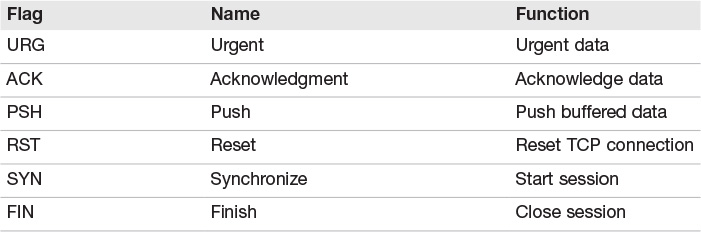
Although there are actually 8 fields (bits) in the 1 byte reserved for flags, the upper two were not defined until 2001 and are not widely used. These include the CWR (Congestion Window Reduced) and ECN (Explicit Congestion Notification Echo) flags.
TCP provides reliable communication by performing formal startup and shutdown handshakes. The TCP three-step handshake occurs before any data is sent. Figure 7.5 illustrates the three-step startup and four-step shutdown.

The flags used to manage three-step startup are SYN and ACK, whereas RST and FIN are used to tear down a connection. FIN is used during a normal four-step shutdown, whereas RST is used to signal the end of an abnormal session. Between the startup and shutdown, TCP guarantees delivery of data by using sequence and acknowledgment numbers. Vulnerabilities that exist at this layer include the TCP sequence number attack that results in session hijacking, and the port-based attack of SYN flooding.
UDP
UDP does not perform any handshaking processes. So although this makes it considerably less reliable than TCP, it does offer the benefit of speed. The UDP header is only 8 bytes in length. There are four 2-byte fields in the header. There are no variations on this. The length is fixed. Figure 7.6 illustrates the operation of UDP.

UDP can be used for services like IPTV (Internet Protocol Television), video multicast, and Voice over IP (VoIP). UDP in VoIP is primarily used for the voice connection portion of the call, and TCP is used for the setup and call control for the actual call. UDP is ideally suited for such applications that require fast delivery. UDP does not use sequence and acknowledgment numbers.
Comparing/Contrasting UDP and TCP
Table 7.4 illustrates the differences between UDP and TCP.

Application Layer
The application or process layer sits at the top of the protocol stack and maps loosely to OSI Layers 6 and 7. This layer is responsible for application support. Applications are typically mapped not by name, but by their corresponding port. Ports are placed into TCP and UDP packets so that the correct application can be passed to the required protocols. Although applications can be made to operate on nonstandard ports, the established port numbers serve as the de facto standard. There are 65,535 ports separated into three ranges, as shown in Table 7.5.

A complete list of ports is at www.iana.org/assignments/port-numbers. Some of the more common well-known applications and their associated ports are as follows:
![]() File Transfer Protocol—FTP is a TCP service and operates on ports 20 and 21. This application moves files from one computer to another. Port 20 is used for the data stream and transfers the data between the client and the server. Port 21 is the control stream and is used to pass commands between the client and the FTP server. Attacks on FTP commonly target clear-text passwords that can be sniffed. FTP is one of the most commonly targeted services.
File Transfer Protocol—FTP is a TCP service and operates on ports 20 and 21. This application moves files from one computer to another. Port 20 is used for the data stream and transfers the data between the client and the server. Port 21 is the control stream and is used to pass commands between the client and the FTP server. Attacks on FTP commonly target clear-text passwords that can be sniffed. FTP is one of the most commonly targeted services.
![]() Telnet—Telnet is a TCP service that operates on port 23. Telnet enables a client at one site to establish a remote session with a host at another site. The program passes the information typed at the client’s keyboard to the host computer system. Telnet can be configured to allow anonymous connections, but should be configured to require usernames and passwords. Unfortunately, even then, Telnet sends them in clear text. When a user is logged in, he or she can perform any task allowed by their user permissions. Applications like Secure Shell version 2 (SSHv2) should be considered as a replacement.
Telnet—Telnet is a TCP service that operates on port 23. Telnet enables a client at one site to establish a remote session with a host at another site. The program passes the information typed at the client’s keyboard to the host computer system. Telnet can be configured to allow anonymous connections, but should be configured to require usernames and passwords. Unfortunately, even then, Telnet sends them in clear text. When a user is logged in, he or she can perform any task allowed by their user permissions. Applications like Secure Shell version 2 (SSHv2) should be considered as a replacement.
![]() Simple Mail Transfer Protocol—This TCP service operates on port 25. It is designed for the exchange of electronic mail between networked systems. Messages sent through SMTP have two parts: an address header and the message text. All types of computers can exchange messages with SMTP. Spoofing, spamming, and open/misconfigured mail relays are several of the vulnerabilities associated with SMTP.
Simple Mail Transfer Protocol—This TCP service operates on port 25. It is designed for the exchange of electronic mail between networked systems. Messages sent through SMTP have two parts: an address header and the message text. All types of computers can exchange messages with SMTP. Spoofing, spamming, and open/misconfigured mail relays are several of the vulnerabilities associated with SMTP.
![]() Domain Name Service—This application operates on port 53 and performs address translation. DNS converts fully qualified domain names (FQDNs) into numeric IP addresses or IP addresses into FQDNs. This system works in a similar way to a phone directory that enables users to remember domain names (such as examcram2.com) instead of IP addresses (such as 114.112.18.23). On some small networks, Network Information Service (NIS) can be used in place of DNS to provide nameserver information and distribute system configuration information. DNS uses UDP for DNS queries and TCP for zone transfers. DNS is subject to poisoning and, if misconfigured, can be solicited to perform a full zone transfer. Security DNS (DNSSEC) is an alternative to DNS. With DNSSEC, the DNS server provides a signature and digitally signs every response. For DNSSEC to function properly, authentication keys have to be distributed before use. Otherwise, DNSSEC is of little use if the client has no means to validate the authentication. You can read more about DNSSEC at www.dnssec.net.
Domain Name Service—This application operates on port 53 and performs address translation. DNS converts fully qualified domain names (FQDNs) into numeric IP addresses or IP addresses into FQDNs. This system works in a similar way to a phone directory that enables users to remember domain names (such as examcram2.com) instead of IP addresses (such as 114.112.18.23). On some small networks, Network Information Service (NIS) can be used in place of DNS to provide nameserver information and distribute system configuration information. DNS uses UDP for DNS queries and TCP for zone transfers. DNS is subject to poisoning and, if misconfigured, can be solicited to perform a full zone transfer. Security DNS (DNSSEC) is an alternative to DNS. With DNSSEC, the DNS server provides a signature and digitally signs every response. For DNSSEC to function properly, authentication keys have to be distributed before use. Otherwise, DNSSEC is of little use if the client has no means to validate the authentication. You can read more about DNSSEC at www.dnssec.net.
Caution
You should be aware that DNSSEC does not provide confidentiality of data, and it does not protect against DDoS attacks.
![]() Bootstrap Protocol (BootP)—BootP is used to download operating parameters to thin clients and is the forerunner to the Dynamic Host Configuration Protocol (DHCP). Both protocols are found on UDP ports 67 and 68.
Bootstrap Protocol (BootP)—BootP is used to download operating parameters to thin clients and is the forerunner to the Dynamic Host Configuration Protocol (DHCP). Both protocols are found on UDP ports 67 and 68.
![]() Trivial File Transfer Protocol (TFTP)—TFTP operates on port 69. It is considered a down-and-dirty version of FTP because it uses UDP to cut down on overhead, and is intended for very small files. It not only copies files without the session management offered by TCP, but it also requires no authentication, which could pose a big security risk. It is typically used to transfer router configuration files and to configure cable modems for cable companies.
Trivial File Transfer Protocol (TFTP)—TFTP operates on port 69. It is considered a down-and-dirty version of FTP because it uses UDP to cut down on overhead, and is intended for very small files. It not only copies files without the session management offered by TCP, but it also requires no authentication, which could pose a big security risk. It is typically used to transfer router configuration files and to configure cable modems for cable companies.
![]() Hypertext Transfer Protocol—HTTP is a TCP service that operates on port 80, and is one of the most well-known protocols that reside at the application layer. HTTP has helped make the Web the popular protocol it is today. The HTTP connection model is known as a stateless connection. HTTP uses a request-response protocol in which a client sends a request and a server sends a response. Attacks that exploit HTTP can target a server, a browser, or scripts that run on the browser. Nimda is an example of code that targets a web server.
Hypertext Transfer Protocol—HTTP is a TCP service that operates on port 80, and is one of the most well-known protocols that reside at the application layer. HTTP has helped make the Web the popular protocol it is today. The HTTP connection model is known as a stateless connection. HTTP uses a request-response protocol in which a client sends a request and a server sends a response. Attacks that exploit HTTP can target a server, a browser, or scripts that run on the browser. Nimda is an example of code that targets a web server.
![]() Internet Message Authentication Protocol—IMAPv4 is an alternative to POP3 that operates on port 143. IMAPv4 offers advantages over POP3, such as enhanced functionality in manipulating a user’s inbox, the capability to better manage mail folders, and optimized online performance. With IMAPv4, email is stored on the mail server and can be accessed from any IMAPv4 email client on the network. With POP3 email is downloaded to the mail client where it is accessed.
Internet Message Authentication Protocol—IMAPv4 is an alternative to POP3 that operates on port 143. IMAPv4 offers advantages over POP3, such as enhanced functionality in manipulating a user’s inbox, the capability to better manage mail folders, and optimized online performance. With IMAPv4, email is stored on the mail server and can be accessed from any IMAPv4 email client on the network. With POP3 email is downloaded to the mail client where it is accessed.
![]() Simple Network Management Protocol—SNMP is a UDP service that operates on ports 161 and 162. It was envisioned to be an efficient and inexpensive way to monitor and remotely configure networks. The SNMP protocol allows agents to gather information, including network statistics, and report back to their management stations. Most large corporations have implemented some type of SNMP management. Some of the security problems that plague versions 1 and 2 of SNMP are caused by the fact that community access strings are passed as clear text and the default community strings (public/private) are well known. SNMP version 3 is the most current form and offers encryption for more robust security.
Simple Network Management Protocol—SNMP is a UDP service that operates on ports 161 and 162. It was envisioned to be an efficient and inexpensive way to monitor and remotely configure networks. The SNMP protocol allows agents to gather information, including network statistics, and report back to their management stations. Most large corporations have implemented some type of SNMP management. Some of the security problems that plague versions 1 and 2 of SNMP are caused by the fact that community access strings are passed as clear text and the default community strings (public/private) are well known. SNMP version 3 is the most current form and offers encryption for more robust security.
![]() Secure Sockets Layer—SSL operates on port 443 and is a secure protocol used to connect to an untrusted network. SSL uses a two-part process to establish communications, and is based on hybrid cryptography. It is the encryption used in HTTPS. Attacks against SSL can be launched if a targeted system supports weak ciphers. In such a situation, an attacker might be able to manipulate the system so that encrypted data is downgraded or even deciphered to achieve access to sensitive data.
Secure Sockets Layer—SSL operates on port 443 and is a secure protocol used to connect to an untrusted network. SSL uses a two-part process to establish communications, and is based on hybrid cryptography. It is the encryption used in HTTPS. Attacks against SSL can be launched if a targeted system supports weak ciphers. In such a situation, an attacker might be able to manipulate the system so that encrypted data is downgraded or even deciphered to achieve access to sensitive data.
![]() Line Printer Daemon—LPD operates on TCP port 515 and is a network protocol used to spool and deliver print jobs to printers.
Line Printer Daemon—LPD operates on TCP port 515 and is a network protocol used to spool and deliver print jobs to printers.
![]() Lightweight Directory Access Protocol—LDAP operates on TCP. LDAP was created as a means to access X.500 directory services. X.500 is a series of computer networking standards covering electronic directory services. LDAP had no data encryption method in versions 1 and 2, whereas version 3 has a much greater security model built in and is supported by TLS.
Lightweight Directory Access Protocol—LDAP operates on TCP. LDAP was created as a means to access X.500 directory services. X.500 is a series of computer networking standards covering electronic directory services. LDAP had no data encryption method in versions 1 and 2, whereas version 3 has a much greater security model built in and is supported by TLS.
![]() Routing Information Protocol—RIP operates on port 520 and allows routing information to be exchanged between routers on an IP network. Even though RIP is usually listed as part of Layer 3, as are the other routing protocols, it is an application. RIP uses UDP ports to send and receive routing information. The original version of RIP has no security and bogus RIP updates can be used to launch DoS attacks.
Routing Information Protocol—RIP operates on port 520 and allows routing information to be exchanged between routers on an IP network. Even though RIP is usually listed as part of Layer 3, as are the other routing protocols, it is an application. RIP uses UDP ports to send and receive routing information. The original version of RIP has no security and bogus RIP updates can be used to launch DoS attacks.
![]() Pretty Good Privacy (PGP)—PGP was developed in 1991 as a free email security application. PGP v5 uses port 11371. PGP was designed to offer military grade encryption, and works well at securing email. Unlike public key infrastructure (PKI), PGP works by using a web of trust. Users distribute and sign their own public keys. Unlike the PKI certificate authority, this web of trust requires users to determine how much they trust the party they are about to exchange keys with. PGP is a hybrid cryptosystem in that it uses both public and private encryption. Sample algorithms PGP can use include Triple DES and Twofish for symmetric encryption, and RSA for asymmetric encryption.
Pretty Good Privacy (PGP)—PGP was developed in 1991 as a free email security application. PGP v5 uses port 11371. PGP was designed to offer military grade encryption, and works well at securing email. Unlike public key infrastructure (PKI), PGP works by using a web of trust. Users distribute and sign their own public keys. Unlike the PKI certificate authority, this web of trust requires users to determine how much they trust the party they are about to exchange keys with. PGP is a hybrid cryptosystem in that it uses both public and private encryption. Sample algorithms PGP can use include Triple DES and Twofish for symmetric encryption, and RSA for asymmetric encryption.
Although there are hundreds of ports and corresponding applications, in practice only a few hundred are in common use. CISSP exam questions on ports will most likely be focused on common ports like these shown in Table 7.6.

LANs and Their Components
A local area network is a critical component of a modern data network. A LAN comprises two or more computers, a communication protocol, a network topology, and cabling or wireless connectivity. A LAN is best defined as computers or other devices that communicate over a small geographical area, such as the following:
![]() A section of a one-story building
A section of a one-story building
![]() The whole floor of a small building
The whole floor of a small building
![]() Several buildings on a small campus
Several buildings on a small campus
LAN Communication Protocols
More than 80% of all LANs use the Ethernet protocol as a means of communication. The Ethernet specification describes how data can be sent between computers in physical proximity. The Digital, Intel, and Xerox (DIX) group first released Ethernet in 1975. Since its introduction, the IEEE Standards Committee has introduced several variations of the Ethernet II protocol, including the following:
![]() IEEE 802.3
IEEE 802.3
![]() IEEE 802.3 with Logical Link Control (LLC)
IEEE 802.3 with Logical Link Control (LLC)
![]() IEEE 802.3 with Subnetwork Access Protocol (SNAP)
IEEE 802.3 with Subnetwork Access Protocol (SNAP)
Although the CISSP exam will not delve very far into the specifics of Ethernet, it is helpful to know the size and structure of these frames. Not including the preamble, an Ethernet frame ranges from 64 to 1,518 bytes. The Ethernet frame uses 18 bytes for control information; therefore, the data in an Ethernet frame can be between 46 and 1,500 bytes long. Figure 7.7 illustrates an 802.3 Ethernet frame.

An older LAN wired networking protocol is token ring, which functions by arranging all the systems in a circle. A special packet, known as a token, travels around the circle. If any device needs to send information, it must capture the token, attach a message to it, and then let it continue to travel around the network.
Network Topologies
The design layout of a network is its topology. Before a network can be installed, a topology must be chosen to match the network’s needs and intended use. Common topologies include bus, star, ring, mesh and fully connected. The sections that follow discuss these topologies in greater detail.
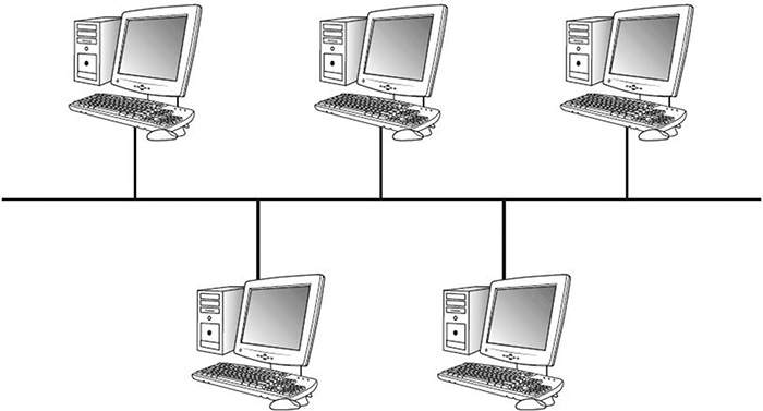
Bus Topology
A bus topology consists of a single cable with multiple computers or devices attached to it. The cable is terminated on each end. In large environments, this is impractical because the medium has physical limitations. Problems range from low speeds to complete network outages; one break can bring down the entire network (see Figure 7.8).
Star Topology
A star topology is the oldest of the three primary network topologies, and was originally used in telephone systems. The star design consists of multiple computers or devices attached to a central switch. Wires radiate outward from the hub in a star-like pattern. Although this scheme uses the most cable, a break will normally affect only one computer. This is the most widely used LAN topology (see Figure 7.9).

Ring Topology
The ring topology is characterized by the fact that there are no endpoints or terminators. It is laid out as a continuous loop of cable, in which all networked computers are attached. Token Ring Copper Distributed Data Interface (CDDI) and FDDI networks use a ring topology (see Figure 7.10). Some ring technologies use Carrier Sense Multiple Access with Collision Avoidance (CSMA/CA). CSMA/CA is a deterministic protocol, whereas CSMA/CD is contention based.

ExamAlert
CISSP test candidates should make sure to understand how CSMA/CD works because it is Ethernet’s media access method. Each device has equal priority when accessing and transmitting data on the wire. Ethernet devices must sense the wire before transmitting. If two devices attempt to transmit simultaneously, a collision occurs. When this happens, the devices retransmit their frames after waiting a random period and sensing the wire again.
Mesh Topology
A mesh network topology is one in which each node relays data for the network. Mesh networks can use either flooding or routing to relay communications.
Fully Connected Topology
A fully connected network connects to all nodes. Although such designs offer great redundancy, the number of connections grows quickly, which makes it impractical for large networks.
ExamAlert
Modern networks commonly implement combinations of network topologies.
LAN Cabling
Even with a defined topology, it is necessary to determine what type of cable will connect the various devices. Cables act as a medium to carry electrical signals between the networked devices. One of two transmission methods can be used:
![]() Baseband—Baseband transmissions use the entire medium to transport a single channel of communication. Ethernet is an example of this baseband transmission scheme.
Baseband—Baseband transmissions use the entire medium to transport a single channel of communication. Ethernet is an example of this baseband transmission scheme.
![]() Broadband—Broadband can support many channels and frequencies on its backbone. Two good examples of broadband are cable television and digital subscriber lines (DSL).
Broadband—Broadband can support many channels and frequencies on its backbone. Two good examples of broadband are cable television and digital subscriber lines (DSL).
Many types of cables can be used for network communications including the following:
![]() Coaxial cable—Coax cable consists of a single solid-copper wire core to carry data signals. This wire is insulated with a Teflon or plastic material, called a dielectric, which is covered with braided shielding used as the signal ground. The entire cable is then coated with plastic (see Figure 7.11). Common types include RG-6 and RG-59. Connectors are typically either BNC or F-connector. Although it was widely used in the early days of networking, its usage has waned.
Coaxial cable—Coax cable consists of a single solid-copper wire core to carry data signals. This wire is insulated with a Teflon or plastic material, called a dielectric, which is covered with braided shielding used as the signal ground. The entire cable is then coated with plastic (see Figure 7.11). Common types include RG-6 and RG-59. Connectors are typically either BNC or F-connector. Although it was widely used in the early days of networking, its usage has waned.

![]() Twisted pair—If you’re in an office, you will probably notice that twisted-pair wiring is being used to connect your computer to a wall jack located nearby. The most common connector terminating this wiring is the RJ-45. Twisted pair can be purchased in a many varieties, one of which is unshielded twisted pair (UTP). UTP is unshielded copper wires, twisted around each other, and insulated in plastic. Not only is it easy to work with, but it is also generally inexpensive. Shielded twisted pair (STP) cable comprises individually insulated twisted wire pairs, as with UTP, but has an additional shielding made of a metallic substance, such as foil. This additional shielding offers support against electromagnetic interference. The primary drawbacks to copper cabling are that it is vulnerable to being tapped and it emanates electrical energy that could possibly be intercepted. The most common types of cabling include: CAT3, CAT5, CAT5e, CAT6, CAT6a, and CAT7. Wiring standards include T568A and T568B. Table 7.7 specifies many table types, lengths, and topologies.
Twisted pair—If you’re in an office, you will probably notice that twisted-pair wiring is being used to connect your computer to a wall jack located nearby. The most common connector terminating this wiring is the RJ-45. Twisted pair can be purchased in a many varieties, one of which is unshielded twisted pair (UTP). UTP is unshielded copper wires, twisted around each other, and insulated in plastic. Not only is it easy to work with, but it is also generally inexpensive. Shielded twisted pair (STP) cable comprises individually insulated twisted wire pairs, as with UTP, but has an additional shielding made of a metallic substance, such as foil. This additional shielding offers support against electromagnetic interference. The primary drawbacks to copper cabling are that it is vulnerable to being tapped and it emanates electrical energy that could possibly be intercepted. The most common types of cabling include: CAT3, CAT5, CAT5e, CAT6, CAT6a, and CAT7. Wiring standards include T568A and T568B. Table 7.7 specifies many table types, lengths, and topologies.

ExamAlert
For the exam, you will want to know that plenum-grade cable is coated with a fire-retardant and is designed to be used in plenum spaces, such as crawlspaces, false ceilings, and below the raised floors in a building. This special coating is fluoropolymers instead of polyethylene vinyl chloride used in nonplenum cables. It is designed to not give off toxic gases or smoke as it burns to help ensure the safety of occupants in case of a fire.
![]() Fiber-optic cable—Whereas twisted pair cable and coax cable rely on copper wire for data transmissions, fiber uses glass. These strands of glass carry light waves encoded to signal the data being transmitted. Common connector types include SC, ST, and LC. Fiber has several advantages, including greater bandwidth, and is somewhat more secure from physical tapping. Basically, two types of fiber cables are in use. They are constructed differently to handle different types of light:
Fiber-optic cable—Whereas twisted pair cable and coax cable rely on copper wire for data transmissions, fiber uses glass. These strands of glass carry light waves encoded to signal the data being transmitted. Common connector types include SC, ST, and LC. Fiber has several advantages, including greater bandwidth, and is somewhat more secure from physical tapping. Basically, two types of fiber cables are in use. They are constructed differently to handle different types of light:
![]() Multimode fiber—Typically used in LANs and powered by light-emitting diodes (LEDs).
Multimode fiber—Typically used in LANs and powered by light-emitting diodes (LEDs).
![]() Single-mode fiber—Typically used in WANs and powered by laser light.
Single-mode fiber—Typically used in WANs and powered by laser light.
Caution
You will want to remember that fiber is more secure than copper cable because it does not radiate signals and requires specialized equipment to tap.
Network Types
Networks of computers can range from small to large. On a very small scale there are personal area networks (PAN). PANs allow a variety of personal and handheld electronic devices to communicate over a short range. The most common type is a wireless PAN (WPAN). Bluetooth is one technology used in support of WPANs.
Although it is nice to know two computers can communicate locally via a local area network (LAN), most need the capability to communicate over a larger geographical region. To communicate between neighboring buildings, a campus area network (CAN) can be used. For those that need to communicate on a citywide level, the metropolitan area network (MAN) was created. A MAN is a network that interconnects a region larger than that covered by a LAN. It can include a city, geographic region, or large area.
If you work for a company that owns several buildings located in different states or countries, that network is part of a wide area network. A WAN spans a geographic distance that is too large for LANs and MANs. WANs are connected by routers. When two LANs are connected together over a distance, they form a WAN.
You might think that just about covers the different network types, but there is one more worth mentioning. Global Area Networks (GANs) offer the interconnection of terminals that do not have a geographical limitation. A GAN can connect computers from various countries or localities from around the world.
Network Storage
Storage area networks (SANs) are networks of storage disks and devices. SANs connect multiple servers to a centralized pool of disk storage. SANs improve system administration by allowing centralized storage instead of having to manage hundreds of servers, each with their own disks. SANs are similar to Network Attached Storage (NAS). One of the big differences is that a NAS appears to the client as a file server or standalone system. A SAN appears to the client as a local disk or volume that is available to be formatted and used locally as needed. SANs are growing in use because of increased server virtualization. SANs can use various types of technologies for connectivity. Several are listed here:
![]() Internet Small Computer System Interface (iSCSI)—A SAN standard used for connecting data storage facilities and allowing remote SCSI devices to communicate. It does not require any special infrastructure and can run over existing IP LAN, MAN, or WAN networks.
Internet Small Computer System Interface (iSCSI)—A SAN standard used for connecting data storage facilities and allowing remote SCSI devices to communicate. It does not require any special infrastructure and can run over existing IP LAN, MAN, or WAN networks.
![]() Fiber Channel over Ethernet (FCoE)—Another transport protocol that is similar to iSCSI. FCoE can operate at speeds of 10 GB per second and rides on top of the Ethernet protocol. Although it is fast, it has a disadvantage in that it is non-routable.
Fiber Channel over Ethernet (FCoE)—Another transport protocol that is similar to iSCSI. FCoE can operate at speeds of 10 GB per second and rides on top of the Ethernet protocol. Although it is fast, it has a disadvantage in that it is non-routable.
![]() Host Bus Adapter (HBA) Allocation—Used to connect a host system to an enterprise storage device. HBAs can be allocated by either soft zoning or by persistent binding. Soft zoning is the most permissive, whereas persistent binding decreases address space and increases network complexity.
Host Bus Adapter (HBA) Allocation—Used to connect a host system to an enterprise storage device. HBAs can be allocated by either soft zoning or by persistent binding. Soft zoning is the most permissive, whereas persistent binding decreases address space and increases network complexity.
![]() LUN Masking—Implemented primarily at the HBA level. It is a number system that makes LUN numbers available to some but not to others. LUN masking implemented at this level is vulnerable to any attack that compromises the local adapter.
LUN Masking—Implemented primarily at the HBA level. It is a number system that makes LUN numbers available to some but not to others. LUN masking implemented at this level is vulnerable to any attack that compromises the local adapter.
Several issues related to SANs include redundancy, replication, snapshots, and duplication. Location redundancy is the concept that data should be accessible from more than one location as a backup. An extra measure of redundancy can be provided by means of a replication service so that data is available even if the main storage backup system fails. Another issue with SANs is the protection of the data. Secure storage management and replication systems are designed to allow a company to manage and handle all corporate data in a secure manner with a focus on the confidentiality, integrity, and availability of the information. The replication service allows for the data to be duplicated and secured so that confidentiality and fault tolerance are achieved. For better fault tolerance, multipath solutions can be used to reduce the risk of data loss or lack of availability by setting up multiple routes between a server and its drives. The multipathing software maintains a listing of all requests, passes them through the best possible path, and reroutes communication if one of the paths dies.
SAN snapshots provide the capability to temporarily stop writing to physical disk to make a point-in-time backup copy. Snapshot software is typically fast and makes a copy quickly, regardless of the drive size.
Finally, am I the only one that ends up with seven different versions of a file? This common problem can be addressed in SANs by means of data de-duplication. It’s simply the process of removing redundant data to improve enterprise storage utilization. Redundant data is not copied. It is replaced with a pointer to the one unique copy of the data. Only one instance of redundant data is retained on the enterprise storage media, such as disk or tape.
Communication Standards
The baseband and broadband communications discussed earlier need to be signaled across the cabling you chose. This signaling can take place in one of three methods:
![]() Simplex—Communication occurs in one direction.
Simplex—Communication occurs in one direction.
![]() Half duplex—Communication can occur in both directions, but only one system can send information at a time.
Half duplex—Communication can occur in both directions, but only one system can send information at a time.
![]() Full duplex—Communication occurs in both directions and both computers can send information at the same time.
Full duplex—Communication occurs in both directions and both computers can send information at the same time.
Something to consider when choosing cabling is how far you need to propagate the signal. Although each communication approach has specific advantages, they share some common disadvantages. These include attenuation and crosstalk. Attenuation is the reduction of signal. As the signal travels farther away from the transmitting device, the signal becomes weaker in intensity and strength. Therefore, all signals need periodic reamplification and regeneration. Figure 7.12 illustrates an example of attenuation.

Your basic choices for signaling are analog or digital transmissions. Both analog and digital signals vary a carrier wave in frequency and amplitude. Analog signals, however, are harder to clean of noise and to determine where the signal ends and where noise begins.
Network Equipment
Telecommunications equipment refers to all the hardware used to move data between networked devices. This includes equipment for LANs and WANs. This is important to know, not only from a networking standpoint, but also to better implement security solutions and pass the CISSP exam.
Repeaters
Repeaters, concentrators, and amplifiers are used to strengthen the communication signal and overcome the problems with attenuation. These devices all operate at OSI Layer 1.
Hubs
Hubs are one of the most basic multiport networking devices. A hub allows all the connected devices to communicate with one another. A hub is logically nothing more than a common wire to which all computers have shared access. Hubs operate at OSI Layer 1. Systems on a hub all share the same broadcast and collision domain.
Hubs have fallen out of favor because of their low maximum throughput. Whenever two or more systems attempt to send packets at the same time on the same hub, there is a collision. As utilization increases, the number of collisions skyrockets and the overall average throughput decreases.
ExamAlert
Don’t spend too much time worrying about repeaters and hubs; just know their basic purpose and that they’ve been replaced by Layer 2 switches.
Bridges
Another somewhat outdated piece of equipment is a wired bridge. Bridges are semi-intelligent pieces of equipment that have the capability to separate collision domains. Bridges examine frames and look up the corresponding MAC address. If the device tied to that MAC address is determined to be local, the bridge blocks the traffic. One big problem with bridges is that, by default, they pass broadcast traffic. Too much broadcast traffic can effectively flood the network and cause a broadcast storm. Almost the only bridges seen today are the wireless bridges used in 802.11x networks.
Old technology? Although items like bridges are rarely seen in the workplace today, exams are notorious for lagging behind the real world. It is also important to understand from a historical perspective how we got to where we are today and to understand corporate security documentation that describes pre-existing technologies.
Switches
A switch performs in much the same way as a hub; however, switches are considered intelligent devices. Switches segment traffic by observing the source and destination MAC address of each data frame. In the classical sense, switches are OSI Layer 2 devices. Modern switches can operate at higher layers. Switches that work at higher levels have the capability to work with different headers.
A sample technology that bridges Layer 2 and Layer 3 is known as Multiprotocol Label Switching (MPLS). MPLS is an OSI Layer 2 protocol. MPLS works with high-speed switches. Commercial switches also offer virtual LAN (VLAN) capabilities. Such switches can operate at OSI Layer 3. VLANs allow a group of devices on different physical LAN segments to communicate with each other as if they were all on the same logical LAN.
Note
The basic difference in Layer 2 switches and those that work at higher layers is the way they deal with addresses and tags.
Switches operate by storing the MAC addresses in a lookup table that is located in random access memory (RAM). This lookup table is also referred to as content addressable memory (CAM). This lookup table contains the information needed to match each MAC address to the corresponding port it is connected to. When the data frame enters the switch, it finds the target MAC address in the lookup table and matches it to the switch port the computer is attached to. The frame is forwarded to only that switch port; therefore, computers on all other ports never see the traffic. Some advantages of a switch are:
![]() Provides higher throughput than a hub
Provides higher throughput than a hub
![]() Provides VLAN capability
Provides VLAN capability
![]() Can be configured for full duplex
Can be configured for full duplex
![]() Can be configured to span a port to support IDS/IPS (intrusion detection system/intrusion prevention system), network feed, or for monitoring
Can be configured to span a port to support IDS/IPS (intrusion detection system/intrusion prevention system), network feed, or for monitoring
Not all switches are made the same. Switches can process an incoming frame in three ways:
![]() Store-and-forward—After the frame is completely input into the switch, the destination MAC is analyzed to block or forward the frame.
Store-and-forward—After the frame is completely input into the switch, the destination MAC is analyzed to block or forward the frame.
![]() Cut-through—This faster design is similar to the store-and-forward switch, but it examines only the first six bytes before forwarding the packet to its rightful owner.
Cut-through—This faster design is similar to the store-and-forward switch, but it examines only the first six bytes before forwarding the packet to its rightful owner.
![]() Fragment Free—This is a Cisco Systems design that has a lower error rate.
Fragment Free—This is a Cisco Systems design that has a lower error rate.
Note
Originally, switches were Layer 2 devices; today, switches can be found at OSI Layer 3 and can work up to OSI Layer 7. Higher-layer switches are known as content switches, content-services switches, or application switches.
Mirrored Ports and Network Taps
Monitoring devices have a harder time examining traffic on switched networks than non-switched networks. To overcome this problem, port mirroring is used. Different vendors use different names for this technology.
![]() Cisco Systems: Switched Port Analyzer (SPAN)
Cisco Systems: Switched Port Analyzer (SPAN)
![]() 3Com: Roving Analysis Port (RAP)
3Com: Roving Analysis Port (RAP)
Port mirroring is used to send a copy of network packets seen on one switch port to a network monitoring connection on another switch port. Therefore, if you are using a managed switch, you can configure port mirroring and easily capture and analyze traffic. Although this works well in corporate environments and in situations where you have control of the managed switch, what about situations where the switch is unmanaged or where someone does not have access to the switch? That is when network taps can be used.
A network tap provides another way to monitor the network and see all traffic, much like what you would see if you were using a hub. This functionality acts as a point to intercept traffic. One handy tool to meet this need is with a Throwing Star LAN Tap. This simple little device allows anyone to easily monitor Ethernet communications. You can find out more at greatscottgadgets.com/throwingstar/.
VLANs
Virtual LANs (VLANs) are used to segment network traffic and result in smaller broadcast domains. VLANs reduce network congestion and increase bandwidth, and do not need to be isolated to a single switch. VLANs can span many switches throughout an organization. Extending VLANs is done by means of a trunking protocol.
A trunking protocol propagates the definition of a VLAN to the entire local area network. Trunking protocols work by encapsulating the Ethernet frame. Two common trunking protocols include the 802.1Q standard and Cisco’s proprietary Inter-Switch Link (ISL) trunking protocol. The 802.1Q standard places information inside the Ethernet frame, whereas ISL wraps the Ethernet frame.
Note
Spanning Tree Protocol (STP) is another protocol that can be used within a VLAN. STP is used to prevent networking loops, build active paths, and provide for backup paths if an active path or link fails. The newest version is Rapid Spanning Tree Protocol (RSTP). It is backward-compatible with STP and provides significantly faster spanning tree convergence.
Trunking security is an important concern in regards to VLANs. A trunk is simply a link between two switches that carries more than one VLAN’s data. A CISSP should be aware that if an attacker can get access to the trunked connection, he can potentially jump from one VLAN to another. This is called VLAN hopping. Making sure that trunked connections are secure so that malicious activity cannot occur is very important.
ExamAlert
VLAN hopping is a hacking technique that enables attackers to send packets outside of their VLAN. These attacks are generally launched by tagging the traffic with a VLAN ID that is outside the attacker’s VLAN.
Routers
Routers reside at Layer 3 of the OSI model. Routers are usually associated with the IP protocol, which sends blocks of data that have been formatted into packets. IP is considered a “best effort” delivery protocol, and IP packets are examined and processed by routers. Routers can connect networks that have the same or different medium types. A router’s primary purpose is to forward IP packets toward their destination through a process known as routing. Whereas bridges and switches examine the physical frame, routers focus on the information found in the IP header. One important item in the IP header is the IP address. As mentioned, an IP address is a logical address; it is laid out in dotted-decimal notation format. The IPv4 address format is four decimal numbers separated by decimal points. Each of these decimal numbers is one byte in length, supporting values from 0 to 255. IPv4 addresses are separated into the following classes:
![]() Class A networks—Consist of up to 16,777,214 client devices. Their address range can extend from 1 to 126.
Class A networks—Consist of up to 16,777,214 client devices. Their address range can extend from 1 to 126.
![]() Class B networks—Host up to 65,534 client devices. Their address range can extend from 128 to 191.
Class B networks—Host up to 65,534 client devices. Their address range can extend from 128 to 191.
![]() Class C networks—Can have 245 devices. Their address range can extend from 192 to 223.
Class C networks—Can have 245 devices. Their address range can extend from 192 to 223.
![]() Class D networks—Reserved for multicasting. Their address range can extend from 224 to 239.
Class D networks—Reserved for multicasting. Their address range can extend from 224 to 239.
![]() Class E networks—Reserved for experimental purposes. Their addresses range from 240 to 254.
Class E networks—Reserved for experimental purposes. Their addresses range from 240 to 254.
ExamAlert
You may have noticed that the 127.0.0.0 address range is missing from the preceding text. Although officially part of the Class Address range, it is used for loopback. Such details may be asked about in the CISSP exam.
Not all the addresses shown can be used on the Internet. Some addresses have been reserved for private use and are considered nonroutable. These private addresses include the following:
![]() Class A—10.0.0.0
Class A—10.0.0.0
![]() Class B—172.16.0.0 to 172.31.0.0
Class B—172.16.0.0 to 172.31.0.0
![]() Class C—192.168.0.0 to 192.168.255.0
Class C—192.168.0.0 to 192.168.255.0
Routers can also be used to improve performance by limiting physical broadcast domains. They act as a limited type of firewall with access control lists (ACLs) filtering, and they ease network management by segmenting devices into smaller subnets instead of one large network. The security of a network’s router is paramount. A compromised router can have devastating consequences, especially if it is used as an endpoint for other services, such as IPSec, a VPN, or a firewall.
ExamAlert
Blocking unauthorized traffic via routers and firewalls is sometimes referred to as bogon filtering. Bogons are simply IP packets that are spoofed and appear to be from an area of the IP address space that is reserved, but not yet allocated or delegated by the Internet Assigned Numbers Authority (IANA) or a delegated Regional Internet Registry (RIR).
Gateways
A gateway connects networks that use dissimilar protocols by converting one software protocol into another. Gateways can be referred to as protocol translators. A gateway can be software-based or a standalone hardware device. Gateways function at OSI Layer 7.
Routing
Routing protocols are a key component of modern networks. Confusion often exists over the terms routed protocol and routing protocol. Both reside at Layer 3. Routed protocols can be forwarded from one router to another. A good example of a routed protocol is IP. A very basic definition of IP is that it acts as the postman of the Internet. Its job is to organize data into a packet, and then address the packet for delivery. IP must place target and source addresses on the packet. This is similar to addressing a package before delivering it to the post office. And please don’t forget the postage: In the world of IP, the postage is a TTL (Time-to-Live). The TTL keeps packets from traversing the network forever, and decrements every time a router is passed. If the recipient cannot be found before the TTL reaches one, the packet will be discarded.
A routing protocol also has a specific role. A routing protocol sends and receives routing information to and from other routers. A routing protocol’s job is that of the large mechanized mail sort machine. Whereas routed protocols, such as IP, build and address a packet, the routing protocol must decide how to best deliver the packet. In real life, there are many ways to get from point A to point B. Likewise, on the Internet, there are many paths to the target network.
Routing protocols can be placed into several basic categories:
![]() Static routing
Static routing
![]() Dynamic routing
Dynamic routing
![]() Default routes
Default routes
Static, or fixed, routing algorithms are not algorithms at all. They rely on a simple table developed by a network administrator mapping one network to another. Static routing works best when a network is small and the traffic is predicable. The big problem with static routing is that it cannot react to network changes. As networks grow, management of these tables can become difficult. Although this makes static routing unsuitable for use on the Internet or large networks, it can be used in special circumstances where normal routing protocols don’t function well.
Dynamic routing uses metrics to determine which path a router should use to send a packet toward its destination. Dynamic routing protocols include RIP, BGP, IGRP, and OSPF. Dynamic routing takes time as all routers must learn about all possible paths. Convergence is reached when all routers on a network agree on the state of routing.
Default routes are similar to static routes. When default routes are used, the designated route becomes the default path the router uses to transmit packets when the router knows no other route to use.
Each time a router receives packets, it must examine them and determine the proper interface to forward the packets to. Not all routing protocols that routers work with function in the same manner. Dynamic routing protocols can be divided into two broad categories:
![]() Algorithms based on distance-vector protocols
Algorithms based on distance-vector protocols
![]() Algorithms based on link-state protocols
Algorithms based on link-state protocols
Distance-vector protocols are based on Bellman-Ford algorithms, and try to find the best route by determining the shortest path. The shortest path is commonly calculated by hops. Distance-vector routing is also called routing by rumor.
RIP is probably the most common distance-vector protocol currently in use. It is a legacy UDP-based routing protocol that does not use authentication, and determines path by hop count. RIP has a 15-hop count maximum and uses broadcast routing updates to all devices. Later versions of RIP provide authentication in clear text. Although RIP works in small networks, it does not operate successfully in large network environments. RIP makes use of split horizon and poison reverse. Split horizon is a route advertisement that prevents routing loops in distance-vector routing protocols by prohibiting a router from advertising a route back onto the router interface from which it was discovered. Poison reverse is a way in which a gateway node tells its neighbor gateways that you can’t get there from here. It basically means that one of the gateways is no longer connected. Poison reverse sets the number of hops to the unconnected gateway to a number that indicates “infinite”: 16 hops.
One major shortcoming of distance-vector protocols is that the path with the lowest number of hops might not be the optimal route. The path with the lowest hop count could have considerably less bandwidth than a route with a higher hop count.
Caution
Distance-vector protocols like RIP can be spoofed and are subject to redirection. It is also easy for attackers to sniff RIP updates. RIP routers update each other by sending out complete routing tables every 30 seconds.
Link-state protocols are based on Dijkstra algorithms. Unlike distance-vector protocols, link-state protocols determine the best path with metrics like delay or bandwidth. When this path is determined, the router informs other routers of its findings. This is how reliable routing tables are developed and routing tables reach convergence. Link-state routing is considered more robust than distance-vector routing protocols. OSPF is probably the most common link-state routing protocol; it is often used as a replacement for RIP.
OSPF is an improved link-state routing protocol that offers authentication. It is an implementation of a link-state-based routing protocol developed in the mid-1980s to overcome the problems associated with RIP. OSPF has several built-in advantages over RIP that include the use of IP multicasts to send out router updates, no limitation on hop count (as with RIP), better support for load balancing, and fast convergence.
Routing protocols can be further divided and defined as interior or exterior routing protocols. RIP, OSPF, and IS-IS are three examples of interior routing protocols. Interior routing protocols are those used within an organization.
Exterior gateway protocols are used by routers connecting different autonomous systems (AS’s). An example of an exterior routing protocol is BGP. BGP is the core routing protocol used by the Internet. It is based on TCP and is used to connect autonomous systems.
Note
An early exterior routing protocol was Exterior Gateway Protocol (EGP). This term is sometimes used synonymously to describe all exterior routing protocols.
WANs and Their Components
WANs are considerably different from LANs. Organizations usually own their own LANs, but WAN services are typically leased; it’s not feasible to have your network guy run a cable from New York to Dallas. WANs are concerned with the long-haul transmission of data and connect remote devices. The Internet is a good example of a WAN. WAN data transmissions typically incur higher costs than LAN transmissions. WAN technologies can be divided into two broad categories: packet switching and circuit switching.
Packet Switching
Packet-switched networks share bandwidth with other devices. Packet-switched networks divide data into packets and frames. These packets are individually routed among various network nodes at the provider’s discretion. They are considered more resilient than circuit-switched networks and work well for on-demand connections with “bursty” traffic. Each packet takes the most expedient route, which means the packets might not arrive in order or at the same time. Packet switching is a form of connectionless networking. A large portion of long-haul data communication is done via fiber. Synchronous optical networking (SONET) is one of the leading technologies that makes this possible. SONET uses light to send multiple digital data streams over the same fiber optical cable.
X.25
X.25 is one of the original packet-switching technologies. Although it is not fast, with speeds up to 56 Kbps, it is reliable and works over analog phone lines.
Frame Relay
Frame Relay is a virtual circuit-switched network. It is a kind of streamlined version of X.25. Frame Relay controls bandwidth use with a committed information rate (CIR). The CIR specifies the maximum guaranteed bandwidth that the customer is promised. The customer can send more data than specified in the CIR if additional bandwidth is available. If there is additional bandwidth, the data will pass; otherwise, the data is marked discard eligible (DE) and is discarded. Frame Relay can use permanent virtual circuits (PVCs) or switched virtual circuit (SVCs). A PVC is used to provide a dedicated connection between two locations. An SVC works much like a phone call in that the connection is set up on a per-call basis, and is disconnected when the call is complete. Switched virtual circuits are good when data transmission is sporadic, and for teleconferencing and phone calls.
Asynchronous Transfer Mode
ATM is a cell-switching-based physical layer protocol. It supports high-bandwidth data needs and works well for time-sensitive applications. Because the switching process occurs in hardware, delays are minimized. ATM uses a fixed cell size of 53 bytes. ATM can be implemented on LANs or WANs.
ATM is being surpassed by newer technologies, such as MPLS, which was mentioned earlier. MPLS designers recognized that data didn’t need to be converted into 53-byte cells. MPLS packets can be much larger than ATM cells. MPLS can provide traffic engineering, and enables the creation of VPNs without end-user applications. MPLS can carry many types of traffic, handles addresses via labels, and does not encapsulate header data.
Note
For the exam, keep in mind that MPLS uses labels to simplify WAN routing and can carry voice and data.
Circuit Switching
Circuit switching comes in either analog or digital configurations. At the heart of circuit level switching is multiplexing. Multiplexing is a technique used to combine multiple channels of data over a single set of wires or transmission path. Today the most common form of circuit switching is the Plain Old Telephone Service (POTS), but ISDN, T-carriers, and digital subscriber line (DSL) are also options. The sections that follow describe these circuit switching options in more detail.
Plain Old Telephone Service
POTS is a voice-grade analog telephone service used for voice calls and for connecting to the Internet and other locations via modem. Modem speeds can vary from 9600 bps to 56 Kbps. Although the POTS service is relatively inexpensive and widely available, it offers only low data speeds.
Integrated Services Digital Network
ISDN is a communication protocol that operates similarly to POTS, except that all-digital signaling is used. Although originally planned as a replacement for POTS, ISDN was not hugely successful. ISDN uses separate frequencies called channels on a special digital connection. It consists of B channels used for voice, data, video, and fax services, and a D channel used for signaling by the service provider and user equipment. Keeping the D signaling data separate makes it harder for attackers to manipulate the service. The D channel operates at a low 16 Kbps; the B channels operate at speeds up to 64 Kbps. By binding the B channels together, ISDN can achieve higher speeds. ISDN is available in two levels: Basic Rate Interface (BRI) at up to 128 Kbps and Primary Rate Interface (PRI) at up to 1.544 Mbps. Basic Rate Interface comprises 2B channels and 1 D channel, and Primary Rate Interface comprises of 23 B channels and 1 D channel.
T-Carriers
T-carrier service is used for leased lines. A leased line is locked between two locations. It is very secure, and users pay a fixed monthly fee for this service, regardless of use. The most common T-carrier is a T1. A T1 uses time-division multiplexing and consists of 24 digital signal 0 (DS0) channels. Each DS0 channel is capable of transmitting 64 Kbps of data; therefore, a T1 can provide a composite rate of 1.544 Mbps. T3s are the next available choice. A T3 is made up of 672 DS0s and has a composite data rate of 45 Mbps. For those who don’t need a full T1 or a full T3, fractional service is available. A fractional T-line is just a portion of the entire carrier. Table 7.8 details common T-carrier specifications and contrasts them with POTS, ISDN, and DSL.

Note
Although T1s are the standard in the United States, Europe uses an E Carrier system. An E1 carries 30 channels; an E3 is 16 E1s. E1s are dedicated 2.048-megabit circuits, and E3 are dedicated 34.368-megabit circuits.
Digital Subscriber Line
DSL is another circuit-switching connectivity option. Most DSLs are asymmetric, which means that the download speed is much faster than the upload speed. The theory is that you usually download more than you upload.
DSL modems are always connected to the Internet; therefore, you do not have to dial in to make a connection. As long as your computer is powered on, it is connected to the Internet and is ready to transmit and receive data. This is the primary security concern of DSL. Unlike the usual lengthy connection time used for dialup service, no waiting time is involved. An advantage of DSL is that it maintains a more fixed speed than cable modems typically do. Table 7.9 details the different DSL types.

Cable Modems
Cable Internet access refers to the delivery of Internet access over the cable television infrastructure. The Internet connection is made through the same coaxial cable that delivers the television signal to your home. The coaxial cable connects to a special cable modem that demultiplexes the TCP/IP traffic. This always-on Internet connection is a big security issue if no firewall is used. One of the weaknesses of cable Internet access is that there is a shared amount of bandwidth among many users. Cable companies control the maximum data rate of each subscriber by capping the maximum data rate. Some unscrupulous individuals attempt to uncap their line to obtain higher speeds. Uncappers can be caught and prosecuted because cable Internet providers routinely check for this illegal action.
Note
Although uncapping a cable connection might lead only to a disconnection of your service, service providers might push for criminal charges. That’s what happened to Brandon Wirtz and other Buckeye Cable customers when their homes were searched by the FBI and they were charged with fifth-degree felonies.
Problems with cable modems continue to be discovered. Some cable modems can be hijacked by nothing more than visiting a vulnerable website, as seen here: www.gnucitizen.org/blog/bt-home-flub-pwnin-the-bt-home-hub/. Another lingering concern is that of the loss of confidentiality. Individuals have worried about the possibility of sniffing attacks. Most cable companies have addressed this issue by implementing the Data Over Cable Service Interface Specification (DOCSIS) standard. The DOCSIS standard specifies encryption and other security mechanisms that prevent sniffing and protect privacy. DOCSIS is currently at version 3.1.
Other WAN Technologies
When systems communicate with each other remotely, a variety of protocols and standards are needed. Some of these include
![]() Switched Multimegabit Data Service (SMDS)—A high-speed, packet-switched service used for MANs and WANs.
Switched Multimegabit Data Service (SMDS)—A high-speed, packet-switched service used for MANs and WANs.
![]() Synchronous Data Link Control (SDLC)—Developed by IBM in the 1970s and used to develop HDLC. SDLC is a Layer 2 communication protocol designed for use with mainframes.
Synchronous Data Link Control (SDLC)—Developed by IBM in the 1970s and used to develop HDLC. SDLC is a Layer 2 communication protocol designed for use with mainframes.
![]() High-Level Data Link Control (HDLC)—Uses a frame format to transmit data between network nodes. It supports full duplex communication and is used in SNA (Systems Network Architecture) network architecture.
High-Level Data Link Control (HDLC)—Uses a frame format to transmit data between network nodes. It supports full duplex communication and is used in SNA (Systems Network Architecture) network architecture.
![]() High-Speed Serial Interface—A connection standard used to connect routers and switches to high-speed networks.
High-Speed Serial Interface—A connection standard used to connect routers and switches to high-speed networks.
Cloud Computing
Cloud computing is an Internet-based approach that provides computing and storage capacity as a service, as illustrated in Figure 7.13. Cloud computing can be broken down into several basic models, including the following:

![]() Infrastructure-as-a-Service (IaaS)—IaaS describes a cloud solution where you are buying infrastructure. You purchase virtual power to execute your software as needed. This is much like running a virtual server on your own equipment, except you are now running a virtual server on a virtual disk. This model is similar to a utility company model because you pay for what you use.
Infrastructure-as-a-Service (IaaS)—IaaS describes a cloud solution where you are buying infrastructure. You purchase virtual power to execute your software as needed. This is much like running a virtual server on your own equipment, except you are now running a virtual server on a virtual disk. This model is similar to a utility company model because you pay for what you use.
![]() Software-as-a-Service (SaaS)—SaaS is designed to provide a complete packaged solution. The software is rented out to the user. The service is usually provided through some type of front-end or web portal. Although the end user is free to use the service from anywhere, the company pays a per-use fee.
Software-as-a-Service (SaaS)—SaaS is designed to provide a complete packaged solution. The software is rented out to the user. The service is usually provided through some type of front-end or web portal. Although the end user is free to use the service from anywhere, the company pays a per-use fee.
![]() Platform-as-a-Service (PaaS)—PaaS provides a platform for your use. Services provided by this model include all phases of the system development life cycle (SDLC) and can use application program interfaces (APIs), website portals, or gateway software. These solutions tend to be proprietary, which can cause problems if the customer moves away from the provider’s platform.
Platform-as-a-Service (PaaS)—PaaS provides a platform for your use. Services provided by this model include all phases of the system development life cycle (SDLC) and can use application program interfaces (APIs), website portals, or gateway software. These solutions tend to be proprietary, which can cause problems if the customer moves away from the provider’s platform.
Voice Communications and Wireless Communications
Technologies like VoIP and wireless capture more attention and use each year. Some studies report that there are more cell phones in China than there are people in the United States. The following sections will look at these technologies.
Voice over IP
In the old days of networking, before the year 2000, multimedia services, such as voice and video, were deployed on stable circuit-switched networks. This guaranteed the bandwidth and the allowed latency could be controlled. Today, many networks use packet-switching technologies. VoIP is the process of using a data network to transmit voice communication. Voice over IP is not a traditional packet-switching protocol, but VoIP is carried on packet-switched networks in IP packets. Networks configured to carry VoIP treat voice communications as just another form of data. This is one of the big changes in networking that has occurred over the last few years. Network convergence refers to the provision of telephone (VoIP), streaming video, and network data communication services, all within a single network. Basically, one pipe is used to transport all forms of communication services. This makes quality of service (QoS) a real concern when discussing VoIP traffic. QoS is used to avoid interruption of phone calls. After all, who wants only a portion of a phone call? QoS can be defined as the capability of the network to provide the following:
![]() Dedicated bandwidth
Dedicated bandwidth
![]() Control of jitter and latency
Control of jitter and latency
These are important goals so that real-time traffic like voice and video can coexist with bursty traffic like HTTP. VoIP has replaced most of the circuit-switched POTS phone service that was common years ago. There is a good chance that if you still have a home phone that it’s actually a VoIP connection. Here are some basic characteristics of VoIP:
![]() SIP-based signaling
SIP-based signaling
![]() User-agent client
User-agent client
![]() User-agent server
User-agent server
![]() Three-way handshake
Three-way handshake
![]() Voice stream carried by RTP
Voice stream carried by RTP
Voice over IP Vulnerabilities
Companies are moving to VoIP because of major cost savings. However, using VoIP is not without risks. As a network service, it is vulnerable in some of the same ways as other data traffic. Attackers can intercept the traffic, hack the VoIP server, or launch a DoS attack against the VoIP server and cause network outages. Attacks against IP phones are also a problem, as are LAN hopping and TFTP alteration for phone firmware image loading. Another consideration is that the vulnerabilities of the operating system the VoIP application is running on are inherited.
One key concern of VoIP is sniffing because protocols like SIP provide little security by default. Without the proper security controls, sniffing a VoIP call can be as easy as using a tool like Wireshark, a common network sniffer. Security issues related to VoIP include the loss of the data network, which can disable VoIP. Other VoIP vulnerabilities include:
![]() Open network—After the VoIP packets leave the organization’s network, the network is not in charge of where they are routed or who might have access to them.
Open network—After the VoIP packets leave the organization’s network, the network is not in charge of where they are routed or who might have access to them.
![]() DoS attacks—Because VoIP uses UDP for portions of the communication process, it is extremely susceptible to disruption or denial of service. VoIP uses an isochronous process in which data must be delivered within strict timelines.
DoS attacks—Because VoIP uses UDP for portions of the communication process, it is extremely susceptible to disruption or denial of service. VoIP uses an isochronous process in which data must be delivered within strict timelines.
![]() Eavesdropping—Because VoIP relies on UDP and Session Initiation Protocol (SIP), it is an open service and communications can potentially be sniffed and replayed. Other protocols used by various vendors of VoIP products include IAX, IAX2, SCCP, and UNISTIM.
Eavesdropping—Because VoIP relies on UDP and Session Initiation Protocol (SIP), it is an open service and communications can potentially be sniffed and replayed. Other protocols used by various vendors of VoIP products include IAX, IAX2, SCCP, and UNISTIM.
![]() Unauthorized phone use—Services like Skype, GoogleTalk, and so on open the corporate network to exposure to attack and can be a potential policy violation. Such tools can even result in a violation of regulation depending on the industry or how they are used.
Unauthorized phone use—Services like Skype, GoogleTalk, and so on open the corporate network to exposure to attack and can be a potential policy violation. Such tools can even result in a violation of regulation depending on the industry or how they are used.
![]() Spam over Internet Telephony (SPIT)—SPIT is bulk unsolicited SPAM delivered using the Voice over Internet Protocol.
Spam over Internet Telephony (SPIT)—SPIT is bulk unsolicited SPAM delivered using the Voice over Internet Protocol.
Note
You can use secure real-time transport protocol (SRTP) to secure VoIP. SRTP uses AES for confidentiality and SHA-1 for integrity.
Cell Phones
Cell phones are another technology that has matured over the years. Cell phone technology can be broadly categorized into the following groups:
![]() 1G—This generation of phones enabled users to place analog calls on their cell phones and continue their conversations as they moved seamlessly from cell to cell around an area or region.
1G—This generation of phones enabled users to place analog calls on their cell phones and continue their conversations as they moved seamlessly from cell to cell around an area or region.
![]() 2G—The second generation changed analog mechanisms to digital cell phones. Deployed in the 1990s, these phones were based on technologies like GSM (Global System for Mobile Communications) and CDMA (Code Division Multiple Access).
2G—The second generation changed analog mechanisms to digital cell phones. Deployed in the 1990s, these phones were based on technologies like GSM (Global System for Mobile Communications) and CDMA (Code Division Multiple Access).
![]() 3G—The third generation changed the phone into a mobile computer, with fast access to the Internet and additional services. Downstream speeds range from 400 Kbps to several megabits per second.
3G—The third generation changed the phone into a mobile computer, with fast access to the Internet and additional services. Downstream speeds range from 400 Kbps to several megabits per second.
![]() 4G—The fourth generation of cell phones were designed to support TV in real time as well as video downloads at much higher speeds. 4G test systems that have been rolled out in South Korea have been demonstrated to support speeds up to a gigabyte of data per second. However, depending on the environment, some indoor or fringe environments can be as low as 100 Mbps. Two of the most widely deployed standards include Mobile WiMAX and Long Term Evolution (LTE).
4G—The fourth generation of cell phones were designed to support TV in real time as well as video downloads at much higher speeds. 4G test systems that have been rolled out in South Korea have been demonstrated to support speeds up to a gigabyte of data per second. However, depending on the environment, some indoor or fringe environments can be as low as 100 Mbps. Two of the most widely deployed standards include Mobile WiMAX and Long Term Evolution (LTE).
Today, most cell phones are 4G. The mobile communication scenario throughout the world is growing at an incredible rate and after the Internet, some might argue that mobile phones are the second most important invention in globalizing the world. Table 7.10 shows common cell phone technologies and their generational level.

One can easily believe the statistic that Americans now spend more time talking on their cell phones than they do on landlines. Mobile phones have revolutionized connectivity; however, they also have given rise to security concerns for organizations because more companies must consider what controls to place on these devices. With so many cell phones in use, there are numerous ways in which attackers can try to exploit their vulnerabilities. One is through the practice of cloning. Cell phones have an electronic serial number (ESN) and an International Mobile Station Equipment Identity (IMEI). Attackers can use specialized equipment to capture and decode these numbers from your phone and install them in another. The attacker then can sell or use this cloned phone. Tumbling is another technique used to attack cell phones. Specially modified phones tumble and shift to a different pair of ESN/IMEI numbers after each call. This technique makes the attacker’s phone appear to be a legitimate roaming cell phone. First-generation cell phones were vulnerable to this attack. GSM phones also make use of an International Mobile Subscriber Identity (IMSI) to identify the user of a cellular network, and is a unique identification associated with all cellular networks. As an example, a IMSI starting with 310 identifies a user in the United States whereas a IMSI starting with 460 identifies the user is from China. People that attack phone systems are called phreakers.
Note
Phone systems can also be the target of Caller ID spoofing and SMShing. Getting a call or text from 867-5309 doesn’t mean that Jenny is waiting to talk to you. You can find a good example of this at www.cbsnews.com/news/cell-phones-easy-id-theft-targets/.
It’s not just cell phones that the security professional has to worry about: Cordless phones also have security issues. Even though cordless phones have moved into the gigahertz range and now use dozens of channels, they are still vulnerable to eavesdropping if someone has the right equipment.
802.11 Wireless Networks and Standards
The 802.11 family of protocols, or 802.11x as it is sometimes called, covers a broad group of wireless standards governed by IEEE. Most of these wireless devices broadcast by using spread-spectrum technology. This method of transmission transmits data over a wide range of radio frequencies. Spread-spectrum technologies include frequency-hopping spread spectrum, an older technology, and sequence spread spectrum. Spread spectrum technology lessens noise interference and allows data rates to speed up or slow down, depending on the quality of the signal. Obstructions like walls, doors, and other solid objects tend to block or reduce signal strength.
Three common methods include the following:
![]() Orthogonal frequency division multiplexing (OFDM)—Splits the signal into smaller subsignals that use a frequency division multiplexing technique to send different pieces of the data to the receiver on different frequencies simultaneously.
Orthogonal frequency division multiplexing (OFDM)—Splits the signal into smaller subsignals that use a frequency division multiplexing technique to send different pieces of the data to the receiver on different frequencies simultaneously.
![]() Direct-sequence spread spectrum (DSSS)—A spread-spectrum technology that uses a spreading code to simultaneously transmit the signal on a small (22 MHz-wide) range of radio frequencies. The wider the spreading code, the more resistant the signal is to interference, but with the cost of a smaller data rate.
Direct-sequence spread spectrum (DSSS)—A spread-spectrum technology that uses a spreading code to simultaneously transmit the signal on a small (22 MHz-wide) range of radio frequencies. The wider the spreading code, the more resistant the signal is to interference, but with the cost of a smaller data rate.
![]() Frequency-hopping spread spectrum (FHSS)—FHSS works somewhat differently from OFDM and DSSS in that it works by taking a broad slice of the bandwidth spectrum, which is divided into smaller subchannels of about 1 MHz. The transmitter then hops between subchannels. Each subchannel is used to send out short bursts of data for a short period. This period is the dwell time. For devices to communicate, each must know the proper dwell time and be synchronized to the proper hopping pattern.
Frequency-hopping spread spectrum (FHSS)—FHSS works somewhat differently from OFDM and DSSS in that it works by taking a broad slice of the bandwidth spectrum, which is divided into smaller subchannels of about 1 MHz. The transmitter then hops between subchannels. Each subchannel is used to send out short bursts of data for a short period. This period is the dwell time. For devices to communicate, each must know the proper dwell time and be synchronized to the proper hopping pattern.
Table 7.11 summarizes the primary standards for wireless LANs (WLANs).

ExamAlert
CISSP exam candidates will be expected to know WLAN standards, speeds, and transmission schemes.
It’s not just wireless access points and equipment that could be a threat to the organization. All wireless devices should have enforced security and strong policies dictating their use. Camera phones allow users to take photos in otherwise secure areas. Smartphones, tablets, and BlackBerrys can be easily lost or stolen. Many forensic tools are available to extract data from these types of wireless devices. Portable wireless devices can also support onboard removable storage that can be lost or removed. It’s unfortunate, but these devices usually lack the level of security of wired devices. Corporate security officers must understand that the default wiping options for many modern devices do not remove all stored data.
Camera phones, tablets, and BlackBerrys have more value than just the cost of the device. These small wireless devices can hold tons of data. The McCain campaign found this out the hard way when, after the 2008 presidential campaign, the campaign started selling off computers, laptops, and BlackBerrys. The problem was that much of this equipment had not been wiped. One such BlackBerry was reported by the buyer to contain many phone numbers of people connected to the campaign, memos, messages, and hundreds of emails that spanned from September 2006 until a few days following the November 4, 2008 election (www.theregister.co.uk/2008/12/12/mccain_blackberry/).
Wireless Topologies
Wireless networks can operate in either ad-hoc mode or infrastructure mode. Adhoc mode, or peer-to-peer, doesn’t need any equipment except wireless network adaptors. Ad-hoc mode allows a point-to-point type of communication that works well for the temporary exchange of information. Infrastructure mode centers around a wireless access point (AP). A wireless AP is a centralized wireless device that controls the traffic in the wireless medium. Wireless devices use CSMA/CA so that they can communicate efficiently. 802.11 wireless NICs can operate in four modes: managed, master, ad-hoc, and monitor mode.
![]() Managed mode is the most generic wireless option. Clients communicate only with the access point and do not directly communicate with other clients.
Managed mode is the most generic wireless option. Clients communicate only with the access point and do not directly communicate with other clients.
![]() Master mode is used by wireless access points to communicate with connected clients in managed mode.
Master mode is used by wireless access points to communicate with connected clients in managed mode.
![]() Ad-hoc mode is a peer-to-peer mode with no central access point.
Ad-hoc mode is a peer-to-peer mode with no central access point.
![]() Monitor mode is a read-only mode used for sniffing WLANs. Wireless sniffing tools like Kismet use monitor mode to sniff 802.11 wireless frames.
Monitor mode is a read-only mode used for sniffing WLANs. Wireless sniffing tools like Kismet use monitor mode to sniff 802.11 wireless frames.
Wireless Standards
The standard for WLANs is IEEE 802.11, commonly called Wi-Fi. Some of the important amendments to this standard include the following:
![]() 802.11a—This amendment defined physical access that could operate in the 5 GHz frequency range and support speeds up to 54 Mbps at a range of 60 feet.
802.11a—This amendment defined physical access that could operate in the 5 GHz frequency range and support speeds up to 54 Mbps at a range of 60 feet.
![]() 802.11b—Operates in the 2.4 GHz frequency range and can reach speeds of up to 11 Mbps and ranges of 300 feet.
802.11b—Operates in the 2.4 GHz frequency range and can reach speeds of up to 11 Mbps and ranges of 300 feet.
![]() 802.11g—This popular amendment operates in the 2.4 GHz frequency range and can support speeds up to 54 Mbps.
802.11g—This popular amendment operates in the 2.4 GHz frequency range and can support speeds up to 54 Mbps.
![]() 802.11i—This amendment provided for secure authentication and encryption that would be a permanent replacement for the deficient Wired Equivalent Privacy (WEP) mechanism. 802.11i also makes use of Robust Security Network (RSN). RSN uses pluggable authentication modules. This allows for changes to cryptographic ciphers as new vulnerabilities are discovered.
802.11i—This amendment provided for secure authentication and encryption that would be a permanent replacement for the deficient Wired Equivalent Privacy (WEP) mechanism. 802.11i also makes use of Robust Security Network (RSN). RSN uses pluggable authentication modules. This allows for changes to cryptographic ciphers as new vulnerabilities are discovered.
![]() 802.11ac—IEEE 802.11ac is a wireless networking standard in the 802.11 family that includes multi-station WLAN throughput of at least 1 gigabit per second and a single link throughput of at least 500 Mbps per second.
802.11ac—IEEE 802.11ac is a wireless networking standard in the 802.11 family that includes multi-station WLAN throughput of at least 1 gigabit per second and a single link throughput of at least 500 Mbps per second.
![]() 802.11n—This version operates in the 2.4 GHz frequency. To enjoy benefits offered by the vendors, purchasers need to stay with one vendor. Resulting data rates can exceed 200 Mbps.
802.11n—This version operates in the 2.4 GHz frequency. To enjoy benefits offered by the vendors, purchasers need to stay with one vendor. Resulting data rates can exceed 200 Mbps.
![]() 802.16—This broadband wireless access standard is also known as WiMAX and was designed to deliver last mile connectivity to broadband users at speeds of up to 75 Mbs. WiMAX is designed to provide wireless broadband access to Internet users in much the same way that cell phones revolutionized wired phone communication.
802.16—This broadband wireless access standard is also known as WiMAX and was designed to deliver last mile connectivity to broadband users at speeds of up to 75 Mbs. WiMAX is designed to provide wireless broadband access to Internet users in much the same way that cell phones revolutionized wired phone communication.
Table 7.12 summarizes the primary standards for wireless LANs (WLANs).

IEEE has written standards in support of our other wireless technologies as well. Bluetooth and RFID (radio frequency identification) are defined by 802.15, written for wireless PANs (WPANs).
Bluetooth
Bluetooth technology is designed for short-range wireless communication between mobile and handheld devices. Bluetooth started to grow in popularity in the mid-to-late 1990s. Versions include, 1.2, 2, 3, and 4. Bluetooth technology has facilitated the growth of a variety of personal and handheld electronic devices. For example, in a WPAN, a smart phone could communicate with a tablet and a laptop. Bluetooth allows these devices to communicate as they come in range of each other or are activated. The classifications of Bluetooth are as follows:
![]() Class 1—This classification has the longest range (up to 100 m) and has 100 mW of power.
Class 1—This classification has the longest range (up to 100 m) and has 100 mW of power.
![]() Class 2—Although this classification is not the most popular, it allows transmission of up to 20 m and has 2.5 mW of power.
Class 2—Although this classification is not the most popular, it allows transmission of up to 20 m and has 2.5 mW of power.
![]() Class 3—This is the most widely implemented classification. It supports a transmission distance of 10 m and has 1 mW of power.
Class 3—This is the most widely implemented classification. It supports a transmission distance of 10 m and has 1 mW of power.
![]() Class 4—This classification supports a transmission distance of .5 m and has .5 mW of power.
Class 4—This classification supports a transmission distance of .5 m and has .5 mW of power.
Note
Although you have most likely heard of Bluetooth, you might not have heard of ZigBee. It’s another wireless standard that is designed for low data rates, can operate for many years, and is well-suited for applications like controlling a light, transferring data from an electrical power meter, or sending temperature data to a thermostat.
Although Bluetooth does have some built-in security features, it has been shown to be vulnerable to attack. At a recent DEF CON security conference, security professionals demonstrated ways to sniff Bluetooth transmissions from up to a kilometer away.
Bluetooth is part of the IEEE 802.15 family of protocols designed for WPANs. Although Bluetooth is extremely popular, competing 802.15 technologies, such as wireless USB and infrared, diversify the market.
Note
Bluejacking involves the unsolicited delivery of data to a Bluetooth user. Bluesnarfing is the actual theft of data or information from a user.
![]() Service Set ID (SSID)—For a computer to communicate or use the WLAN, it must be configured to use the WLAN’s SSID. The SSID distinguishes one wireless network from another.
Service Set ID (SSID)—For a computer to communicate or use the WLAN, it must be configured to use the WLAN’s SSID. The SSID distinguishes one wireless network from another.
![]() Wireless access point—A wireless access point is a centralized wireless device that controls the traffic in the wireless medium and can be used to connect wireless devices to a wired network.
Wireless access point—A wireless access point is a centralized wireless device that controls the traffic in the wireless medium and can be used to connect wireless devices to a wired network.
![]() Wireless networking cards—Used to connect devices to the wireless network.
Wireless networking cards—Used to connect devices to the wireless network.
![]() Encryption—802.11 encryption was originally provided by the aging WEP protocol, which was intended to provide the same level of privacy as a user might have on a wired network. WEP used RC4 symmetric encryption, but it was a flawed implementation. The amendment offering a secure replacement for WEP is 802.11i, which has become popularized by the Wi-Fi Alliance as Wi-Fi Protected Access (WPA, still using RC4) and WPA2 (uses Advanced Encryption Standard (AES)). These encryption mechanisms are discussed in detail in the next section.
Encryption—802.11 encryption was originally provided by the aging WEP protocol, which was intended to provide the same level of privacy as a user might have on a wired network. WEP used RC4 symmetric encryption, but it was a flawed implementation. The amendment offering a secure replacement for WEP is 802.11i, which has become popularized by the Wi-Fi Alliance as Wi-Fi Protected Access (WPA, still using RC4) and WPA2 (uses Advanced Encryption Standard (AES)). These encryption mechanisms are discussed in detail in the next section.
In North America, 802.11 supports bandwidth at 2.4 GHz for 11 channels, three of which (1, 6, and 11) can be used simultaneously as non-overlapping. The channel designates the frequency on which the network will operate. European units support 13 channels (up to 4 non-overlapping) and Japanese units support 14 channels. There are 24 non-overlapping channels at 5 GHz. Worldwide, frequency availability changes according to the pertinent licensing authority. Equipment adjusts to these demands by asking what country the installation is occurring in, and either adjusting the frequencies to the local authority, or terminating transmissions (according to the licenses that the vendor is granted). The 802.11d amendment enables client equipment to ask what country it finds itself in and dynamically adjust its frequencies.
Note
Two very basic wireless security precautions include MAC address filtering and Service Set Identifier (SSID) filtering. Both provide only limited security as MAC address are transmitted in the clear, and thus can be easily sniffed. Setting SSIDs to non-broadcast is also a poor security strategy because wireless sniffers, such as Kismet, can detect the non-broadcast SSID used by clients to bypass this weak control.
Wireless Protection Mechanisms
The original technology used to protect wireless was WEP. WEP is implemented at the data link layer and encrypts data with the RC4 encryption algorithm. The key was limited to 40 bits because of export rules that existed during the late 1990s when the 802.11 protocol was developed. Forty bits is considered a very weak key today.
WEP is based on the RC4 algorithm that used either a 64-bit (IEEE standard) or a 128-bit (commercial enhancement) key. However, the keys can’t use that many bits because a 24-bit initialization vector (IV) was used to provide randomness. The “real key” is actually 40 or 104 bits long. Many people are reluctant to learn about such an old and broken technology as WEP; however, it is important to appreciate that WEP is still with us. Credit card information has been stolen from vendors because of the use of WEP. The PCI Security Standards Council has revised its rules on credit card transactions to prohibit the use of WEP, and this equipment was phased out in 2010.
WEP is known as static WEP because everyone has the same key. Two of the first weaknesses realized about WEP are that this static encryption key was the same key being used for the shared key authentication (SKA), and that the authentication used a challenge-handshake mechanism that was dictionary-crackable. The immediate solution was to throw away SKA, and use only open system authentication (OSA) and the WEP encryption key. Everyone could connect, but no one could communicate without the encryption key.
One way the industry responded to these potential issues was by incorporating 802.1X (port-based access) into many wireless devices. When used in conjunction with extensible authentication protocol (EAP), it can be used to authenticate devices that attempt to connect to a specific LAN port. Although this was an improvement over WEP, 802.1x has been shown to be vulnerable.
To better understand the WEP process, you need to understand how the exclusive-or (XOR) function works in Boolean logic. Specifically, XORing means exclusively or, never both. XORing is just a simple binary comparison between two bits that produces another bit as the result. When the two bits are compared, XORing looks to see whether they are different. If the answer is yes, the resulting output is a 1. If the two bits are the same, the result is a 0. Let’s look at the seven steps of encrypting a message:
1. The transmitting and receiving stations are initialized with the secret key. This secret key must be distributed using an out-of-band mechanism like email, posting it on a website, or giving it to you on a piece of paper the way many hotels do.
2. The transmitting station produces a seed, which is obtained by appending the 40-bit secret key to the 24-bit IV, for input into a Pseudo-Random Number Generator (PRNG).
3. The transmitting station uses the secret key and a 24-bit IV as input into the WEP PRNG to generate a key stream of random bits.
4. The key stream is XORed with plain text to obtain the cipher text.
5. The transmitting station appends the cipher text to a copy of the IV for the receiver to use, and sets a bit in the header to indicate that the packet is WEP-encrypted, and the WEP frame is transmitted. Because WEP encrypts at OSI Layer 2, the Layer 2 header and trailer are sent in clear text.
6. The receiving station checks to see whether the encrypted bit of the frame it received is set. If so, the receiving station extracts the IV from the frame and inputs it and the secret key into its WEP PRNG.
7. The receiver generates the same key stream used by the transmitting station, and XORs it with the cipher text to obtain the sent plain text.
WEP’s immediate successor was a stop-gap measure that was popularized as Wi-Fi Protected Access (WPA). This name was born out of hardware certification testing by the Wi-Fi Alliance. WPA certification meant that a piece of hardware was compliant with a snapshot of the 802.11i amendment; the amendment itself was still under design. One of the jobs of the 802.11i task group was to reverse-engineer WEP, and develop a software-only upgrade for wireless users that would deploy Temporal Key Integrity Protocol (TKIP) for encryption. TKIP scrambles the user key with network state information using a mixing algorithm, and adds an integrity-checking feature that was much stronger than WEP had to verify the frames haven’t been tampered with. WPA certification tested equipment for the implementation of TKIP.
In 2004, IEEE completed the 802.11i amendment, and released Counter Mode with Cipher Block Chaining Message Authentication Code Protocol (CCMP), an AES solution, as a complete replacement for the outdated RC4 mechanism used in WEP and TKIP. CCMP is also tested for and certified by the Wi-Fi Alliance, and is recognized as WPA2. Don’t be surprised to see key sizes of up to 256 bits, which is a vast improvement over the original 40-bit encryption WEP used. Just keep in mind that in the IT security field, nothing remains static. Additional tools and techniques continue to be developed to attack newer security mechanisms like WPA. coWPAtty is one such tool.
War driving is the practice of driving around, finding, mapping, and possibly connecting to open wireless networks. Tools like NetStumbler, Kismet, and AirSnort are typical tools that might be used to aid the war driver.
War chalking is the practice of marking the location and status of wireless networks. The practice can be traced to symbols used by hobos during the depression to mark the location of food and work.
Other Wireless Technologies
As technology continues to change, other standards are emerging. One example is i-Mode. i-Mode is the packet-based service for mobile phones used in Japan. Another is Digital Enhanced Cordless Communication (DECT). This technology is widely used for cordless phone technology outside the U.S. DECT is the standard for cordless phones and allows different handsets and base units to work together from different manufacturers.
Still another standard you should know is Wireless Application Protocol (WAP). WAP is an open standard to help cell phone users get the same types of content available to desktop and laptop users. A WAP-enabled device customizes the content of a website to work with the small screen size of a mobile phone. A key component of this technology is wireless markup language (WML). Security issues in WAPv1 have been fixed by WAPv2. Anyone considering the use of WAP for sensitive information exchange should understand these issues. WAP was created by the WAP Forum, and was an attempt to rewrite the upper layers of the OSI to minimize the overhead of a mini-browser inside the cell phone. The Forum created its own encryption protocol called WTLS, which was a rewrite of transport layer security (TLS). When a client’s signal reached the ISP’s gateway, the WTLS packet had to be decrypted from WTLS to re-encapsulate it as a TLS signal and then to send it onto the Internet. This was a vulnerable moment, where data was fully decrypted, and it became known as the GAP in WAP (see Figure 7.14). WAP2 has been rewritten as an abbreviated form of TLS instead of WTLS, and the packet no longer needs to be decrypted.

Network Access Control Devices
Security should be implemented in layers to erect several barriers against attackers. One good example of a network access control is a firewall. The firewall can act as a choke point to control traffic as it ingresses and egresses the network. Another network access control is the DMZ (demilitarized zone), which establishes a safe zone for internal and external users to work. The sections that follow describe these network security devices and techniques in more detail.
Firewalls
The term firewall has been used since the 1990s and describes a device that guards the entrance to a private network. Firewalls were developed to keep unauthorized traffic out. Firewalls have undergone generations of improvements so that today several different types of firewalls exist. These include the packet filter, application proxy, circuit proxy, and stateful inspection. It’s a sad fact that we need firewalls. Just as in the real world, some individuals enjoy destroying other people’s property. A firewall is a computer, router, or software component implemented to control access to a protected network. It enables organizations to protect their network and control traffic. Remember that models addressed here, such as stateful inspection and proxies, are theoretical, so most vendor products will not match one design perfectly.
Packet Filters
Packet filters are devices that filter traffic based on IP addresses. Savvy hackers use spoofing tools and other programs that are easily available on the Internet to bypass packet filters. The first firewalls ever implemented were packet filters. These devices inspect the TCP/IP headers and make a decision based on a set of predefined rules. Packet filters simply drop packets that do not conform to the predefined rule set. These devices are considered stateless. Packet filters are configured by compiling an access control list. ACLs can deny or permit packet transmission based on IP addresses, protocol types, TCP ports, and UDP ports.
Stateful Firewalls
Stateful firewalls keep track of every communication channel by means of a state table. Because of this, they are considered intelligent firewalls. They’re part of the third generation of firewall design. Packet filters do not have this capability.
Proxy Servers
By definition, the word proxy means “to stand in place of.” Therefore, an Internet proxy is a hardware or software device that can perform address translation and that communicates with the Internet on behalf of the network. The real IP address of the user remains hidden behind the proxy server. The proxy server can also be configured to filter higher-layer traffic to determine whether the traffic is allowed to pass. Proxy servers offer increased security because they don’t allow untrusted systems to have a direct connection to internal computers. Proxy servers function as follows:
1. Accept packets from the external network.
2. Copy the packets.
3. Inspect them for irregularities.
4. Change the addresses to the correct internal device.
5. Put them back on the wire to the destination device.
Other types of proxies include the following:
![]() Application-level proxy—Not all proxies are made the same. Application-level proxies inspect the entire packet and then make a decision based on what was discovered while inspecting the contents. This method is very thorough and slow. For an application-level proxy to work correctly, it must understand the protocols and applications it is working with.
Application-level proxy—Not all proxies are made the same. Application-level proxies inspect the entire packet and then make a decision based on what was discovered while inspecting the contents. This method is very thorough and slow. For an application-level proxy to work correctly, it must understand the protocols and applications it is working with.
![]() Circuit-level proxy—A circuit-level proxy closely resembles a packet-filtering device in that it makes decisions based on addresses, ports, and protocols. It does not care about higher-layer applications, so it works for a wider range of protocols but doesn’t provide the depth of security that an application-level proxy does. SQUID is an example of an open-source proxy. Table 7.13 summarizes the primary differences between application- and circuit-level proxies.
Circuit-level proxy—A circuit-level proxy closely resembles a packet-filtering device in that it makes decisions based on addresses, ports, and protocols. It does not care about higher-layer applications, so it works for a wider range of protocols but doesn’t provide the depth of security that an application-level proxy does. SQUID is an example of an open-source proxy. Table 7.13 summarizes the primary differences between application- and circuit-level proxies.

Caution
An application-level proxy provides a high level of security and offers a very granular level of control. Its disadvantages include the possibility that it could break some applications and that it can be a performance bottleneck.
![]() SOCKS—SOCKS takes the proxy servers concept to the next level. SOCKS must be deployed as a client and server solution. It provides a secure channel between the two devices. It examines individual applications to determine whether they are allowed access. Common SOCKS applications include:
SOCKS—SOCKS takes the proxy servers concept to the next level. SOCKS must be deployed as a client and server solution. It provides a secure channel between the two devices. It examines individual applications to determine whether they are allowed access. Common SOCKS applications include:
![]() FTP—Blocks or allows files to be transferred into or out of the network
FTP—Blocks or allows files to be transferred into or out of the network
![]() HTTP—Blocks or allows Internet access
HTTP—Blocks or allows Internet access
![]() SMTP—Blocks or allows email
SMTP—Blocks or allows email
Demilitarized Zone
In the computer world, the DMZ prevents outsiders from getting direct access to internal services. DMZs are typically set up to allow external users access to services within the DMZ. Basically, shared services like Internet, email, and DNS might be placed within a DMZ. The DMZ provides no other access to services located within the internal network. If an attacker is able to penetrate and hack computers within the DMZ, no internal computers should be accessible (as long as no internal machines trust these DMZ computers). Usually the computers placed in the DMZ are bastion hosts. A bastion host is a computer that has had all unnecessary services and applications removed; it has been hardened against attack. To add security to the devices in the DMZ, a screened host is sometimes used. A screened host is a firewall partially shielded by a router acting as a packet filter. This furthers exemplifies the concept of defense in depth.
NAT
Network Address Translation (NAT) was originally developed because of the explosive growth of the Internet and the increase in home and business networks; the number of available public IP addresses is insufficient to support everyone. NAT allows a single device, such as a router, to act as an agent between the Internet and the local network. This device or router provides a pool of addresses for use by your local network. Only a single, unique IP address is required to represent this entire group of computers. The outside world is unaware of this division and thinks that only one computer is connected. NAT can provide a limited amount of security because it can hide internal addresses from external systems. When private addressing is used, NAT is a requirement because packets with private IP addresses cannot be routed to external IP addresses, and external traffic cannot be routed into the NATed network. RFC 1918 defines the three ranges of private addresses on the 10.0.0.0-10.255.255.255, 172.16.0.0-172-31.255.255, and 192.168.0.0-192.168.255.255 network ranges. Common types of NAT include the following:
![]() Static NAT—Uses a one-to-one mapping between public and private IP addresses.
Static NAT—Uses a one-to-one mapping between public and private IP addresses.
![]() Dynamic NAT—Uses a pool of public addresses. When internal devices need Internet connectivity, they are mapped to the next available public address. When the communication session is complete, the public address is returned to the pool.
Dynamic NAT—Uses a pool of public addresses. When internal devices need Internet connectivity, they are mapped to the next available public address. When the communication session is complete, the public address is returned to the pool.
![]() Port Address Translation (PAT)—Most home networks using DSL or cable modems use this type of NAT. It is designed to provide many internal users Internet access through one external address.
Port Address Translation (PAT)—Most home networks using DSL or cable modems use this type of NAT. It is designed to provide many internal users Internet access through one external address.
Firewall Design
Firewall designs include packet filtering, dual-homed gateway, screened host, and screened subnet. A single tier packet-filter design has one packet-filtering router installed between the trusted and untrusted network, usually the Internet and the corporation’s network. A dual-homed gateway is an improvement over the basic packet-filtering router because it comprises a bastion host that has two network interfaces. One important item is that IP forwarding is disabled on the host. Additional protection can be provided by adding a packet-filtering router in front of the dual-homed host. The screened host firewall adds a router and screened host (see Figure 7.15).

The router is typically configured to see only one host computer on the intranet network. Users on the intranet have to connect to the Internet through this host computer, and external users cannot directly access other computers on the intranet. In this configuration, only one network interface card is needed for the application gateway or the screening host. The screened subnet sets up a DMZ.
Remote Access
Well-designed networks will always require authentication and access control. You might be internal to the organization, or in a hotel on the road. Being outside the organization raises other concerns besides proper authentication, such as confidentiality and privacy. This section discusses an array of topics, including the Password Authentication Protocol (PAP), the Challenge Handshake Authentication Protocol (CHAP), VPNs, and IPSec.
Point-to-Point Protocol
Point-to-Point Protocol (PPP) is the most commonly used protocols for dialup connections. It can run on a line of any speed, from POTS to T1. Developed in 1994 by the IETF, PPP is a replacement to Serial Line IP (SLIP). SLIP is capable of carrying only IP and had no error detection, whereas PPP supports many types of authentication, including PAP, CHAP, and EAP.
Password Authentication Protocol
PAP uses a two-way handshake to authenticate a client to a server when a link is initially established. PAP is vulnerable because it sends the password in clear text, which makes it highly vulnerable to sniffing attacks.
Challenge Handshake Authentication Protocol
CHAP is an improved version of the PAP protocol. It uses a four-way handshake to authenticate the client. CHAPv2 provides for mutual authentication. When a client requests authentication, the server sends the client a challenge. The client hashes the challenge with its password and returns it to the server. This hashed value is compared on the server with a hash that the server created. Although no plain text ever crosses the network, anyone knowledgeable of the hashing functions and who captures the exchange can use a dictionary attack in an attempt to defeat the mechanism. CHAP was specifically created to defeat replay attacks because the challenge would vary with each client request, and reauthentications could be periodically demanded by the server.
Extensible Authentication Protocol
EAP makes PPP more robust by adding the capability to implement a variety of authentication mechanisms, including digital certificates, token cards, and MD5-Challenge. EAP is used with 802.1X, and implemented in amendments, such as those of 802.11i, WPA-enterprise, and WPA2-enterprise. When used by wireless devices to authenticate end users or devices, the client (supplicant) initiates the EAP request to the wireless access point (authenticator) that is responsible for keeping the network port closed until the authentication process completes successfully. The authenticator becomes a proxy, forwarding requests and replies between the supplicant in the authenticating server (RADIUS [Remote Authentication Dial-in User Service], TACACS+, and so on). During this protected series of frames, usually inside an encrypted tunnel, a pair-wise master key (PMK) is developed between the supplicant and the authenticating server. If the authentication exchange is successful, the authenticating server delivers this PMK to the access point. The PMK is used to develop transient AES or TKIP encryption keys for the duration of the client’s session. Table 7.14 summarizes some of the different types of EAP.

ExamAlert
Although EAP-TLS is one of the most secure and most costly, EAP can be implemented in many different ways. Some methods including EAP-MD5, EAP-TLS, EAP-SIM, LEAP, and EAP-TTLS. Although EAP-MD5 is not appropriate for use by itself (a simple hash), and LEAP is dictionary-crackable; the other EAP types are robust. The goal is not for you to memorize each one these in detail, but to understand that as a CISSP, you must be able to select the appropriate protocol, depending on the policy established for authentication strength.
Remote Authentication Dial-in User Service
RADIUS was designed to support dialup users and originally used a modem pool to connect to the organization’s network. Because of the features RADIUS offers, it is now used for more than just dialup users. Enterasys uses it for secure network products, and 802.1X/EAP also uses it widely. A RADIUS server contains usernames, passwords, and other information to validate the user (supplicant). Supplicant refers to the client machine that wants to gain access to the network. RADIUS is a well-known UDP-based authentication and accountability protocol. Information is passed to the NAS, which is the RADIUS client. The RADIUS client then forwards the information to the RADIUS server to be authenticated. Traffic from the RADIUS client to RADIUS server typically protects the password by means of a shared secret. RADIUS has improved with the IETF’s approval of Diameter, and continues to be the most widely deployed AAA (Authentication, Authorization, and Accounting) server.
Terminal Access Controller Access Control System
TACACS is an access-control protocol used to authenticate a user logging onto a network. TACACS is a UDP-based protocol that provides authentication, authorization, and accountability. It was originally used in Cisco devices. TACACS is very similar to RADIUS. When TACACS receives an authentication request, it forwards the received username and password to a central database. This database verifies the information received and returns it to TACACS to allow or deny access based on the results. The fundamental reason TACACS did not become popular is because TACACS is a proprietary solution from Cisco, and its use would require the payment of royalties. TACACS+ is a completely new rewrite of the protocol and separates authentication and authorization. TACACS+ is not compatible with TACACS. TACACS+ is TCP-based and offers extended two-factor authentication. When most people today say “TACACS,” they mean TACACS+.
IPsec
IPSec was developed to provide security for IP packets. Without IPSec, someone could capture, read, or change the contents of data packets and then send them back to the unsuspecting target. The current version of IP, IPv4, supports IPSec as an add-on; IPv6 has IPSec built in. IPSec offers its users several levels of cryptographic security:
![]() Authentication header (AH)—Protects data against modification; does not provide privacy.
Authentication header (AH)—Protects data against modification; does not provide privacy.
![]() Encapsulating security payload (ESP)—Provides privacy and protects against malicious modification.
Encapsulating security payload (ESP)—Provides privacy and protects against malicious modification.
![]() Internet key exchange (IKE)—Allows secret keys to be exchanged securely before communications begin.
Internet key exchange (IKE)—Allows secret keys to be exchanged securely before communications begin.
Key exchange is something that must be handled securely. IPSec uses Internet Security Association and Key Management Protocol (ISAKMP). It is defined by RFC 2408 and is used for establishing Security Associations (SA) and cryptographic keys in an Internet environment. Basically, it defines procedures and formats to establish, negotiate, modify, and delete SAs, and defines payloads for exchanging key generation and authentication data. Each has an IP protocol number; ESP is protocol 50, and AH is protocol 51. Because IPSec is applied at OSI Layer 3, any layer above Layer 3 can use it transparently. Other Internet security systems in widespread use, such as Transport Layer Security (TLS) and Secure Shell (SSH), operate in the upper layers at the OSI model. IPSec has two modes of operation:
![]() Transport mode—Protects just the payload.
Transport mode—Protects just the payload.
![]() Tunnel mode—Protects the payload and the header. In this configuration, IPSec acts as a gateway; traffic for any number of client computers can be carried. IPSec in tunnel mode provides link encryption and is compatible with IPv6. It can be used to encrypt any traffic supported by IP.
Tunnel mode—Protects the payload and the header. In this configuration, IPSec acts as a gateway; traffic for any number of client computers can be carried. IPSec in tunnel mode provides link encryption and is compatible with IPv6. It can be used to encrypt any traffic supported by IP.
See Figure 7.16 to better understand the differences between the two modes.

Three different implementation architectures are defined for IPsec in RFC 2401. These include host to gateway, gateway-to-gateway, and host-to-host.
![]() Host to gateway—Used to connect one system that runs IPsec client software to an IPsec gateway.
Host to gateway—Used to connect one system that runs IPsec client software to an IPsec gateway.
![]() Gateway-to-gateway—Connects two IPsec gateways to form an IPsec connection that acts as a shared routable network connection.
Gateway-to-gateway—Connects two IPsec gateways to form an IPsec connection that acts as a shared routable network connection.
![]() Host-to-host—Connects two systems to each other via IPsec.
Host-to-host—Connects two systems to each other via IPsec.
Message Privacy and Multimedia Collaboration
New technologies make it possible to monitor all types of information that one individual might send to another. Bullrun is one example of such a program. This controversial program was developed by the National Security Agency (NSA) to give the U.S. government the means to defeat the encryption used in specific network communication technologies. Its full capability is unknown.
Some Internet applications have little or no built-in security. Instant messaging (IM) is a good example. Many corporations allow or use IM, but it was built for chatting, not security. Most IM applications lack encryption capabilities, have insecure password management, and have features that actively work to bypass firewalls. IM can be vulnerable to sniffing attacks, can be used to spread viruses and worms, and can be targeted for buffer overflow attacks. If these programs are going to be used, security controls like the Pidgin encryption plug-ins and SSL-based chat should be considered. Although IM is not as popular as it once was, IM products are all highly vulnerable to malware, such as worm viruses, backdoor Trojan horses, hijacking, impersonation, and denial of service. IM can also be used to exfiltrate sensitive information.
Web conferencing is a low-cost method that allows people in different locations to communicate over the Internet. Though useful, web conferencing can potentially be sniffed and intercepted by an attacker. Common solutions include Adobe Connect, GoToMeeting, and Microsoft Office Live Meeting. These technologies usually include displaying PowerPoint slides, sharing audio or video, or even sharing documents. Some solutions allow users to remotely control another connected PC.
Remote meeting and web conferencing software is typically designed tunnel outbound SSL or TLS traffic. These technologies often pass outside the corporate network and as such should be understood, controlled, and made compliant with all applicable policy as they offer attackers and others the ability to exfiltrate data.
Finally, there is email. It’s another common network application and in its native state can be very insecure. Sending an email message is much like your parents sending a postcard about their vacation to you through the U.S. mail. Anyone who happens to see the card during transit can read the message they sent you from their trip to Kathmandu. If you need a little privacy, you must use encryption. Using encryption is the equivalent of sending a coded letter in a sealed envelope: Even if someone opens the sealed envelope, the coded letter will prevent anyone from learning about your parents’ trip to Kathmandu to see Mount Everest. Email protection mechanisms include PGP, Secure Multipurpose Internet Mail Extensions (S/MIME), and Privacy Enhanced Mail (PEM).
Exam Prep Questions
1. You are a security consultant for a new company that is going to sell products online. Customers will be expected to pay for their products on the company website. It is necessary to establish a secure connection between two TCP-based machines to ensure web communications for financial transactions. You have been asked to suggest some type of extensible authentication protocol to help secure this traffic. Which version would you consider the most secure but also the most costly?
![]() A. EAP-LEAP
A. EAP-LEAP
![]() B. EAP-MD5
B. EAP-MD5
![]() C. EAP-TLS
C. EAP-TLS
![]() D. EAP-SIM
D. EAP-SIM
2. You just overheard two people discussing ways to steal electronic serial numbers (ESNs). What type of attack are they discussing?
![]() A. Bank card hacking
A. Bank card hacking
![]() B. Modem hacking
B. Modem hacking
![]() C. PBX hacking
C. PBX hacking
![]() D. Cell phone hacking
D. Cell phone hacking
3. You are a security consultant for a company that has a location in Houston, Texas, New York City, and Dallas, Texas. Your client requires link-to-link communications from the LAN to the WAN for data/traffic encryption supported by IP that includes encryption and authentication. They will be using L2TP at L3 of the OSI model. The CIO for the company plans to migrate to IPv6 over the next year so he needs something that will be compatible with IPv6. What is the BEST protocol to use for your client?
![]() A. IPSec Transport mode
A. IPSec Transport mode
![]() B. IPSec Tunnel model
B. IPSec Tunnel model
![]() C. PPTP
C. PPTP
![]() D. L2F
D. L2F
4. Which of the following is a mechanism for converting internal IP addresses found in IP headers into public addresses for transmission over the Internet?
![]() A. ARP
A. ARP
![]() B. DNS
B. DNS
![]() C. DHCP
C. DHCP
![]() D. NAT
D. NAT
5. Samuel has been asked to start the implementation of IPv6 on an existing IPv4 network. The current system has no native connection to an IPv6 network. It has about 130 hosts. The internal routing protocol is OSPF. Which technology would you recommend that Samuel use?
![]() A. VRRP
A. VRRP
![]() B. Teredo
B. Teredo
![]() C. 802.1AE
C. 802.1AE
![]() D. 6to4
D. 6to4
6. You have been brought on as a consultant to a small non-profit where they are using a routing protocol that is based on Bellman-Ford algorithms. Although the network has reached convergence, one path is no longer available and shows an infinite hop count. What is the proper term to describe this situation?
![]() A. Loopback
A. Loopback
![]() B. Split horizon
B. Split horizon
![]() C. Classless Inter-Domain Routing
C. Classless Inter-Domain Routing
![]() D. Poison reverse
D. Poison reverse
7. Which of the following is considered a current updated standard to the WEP protocol?
![]() A. WPA2
A. WPA2
![]() B. SMLI
B. SMLI
![]() C. PGP
C. PGP
![]() D. POP
D. POP
8. Which of the following closely resembles a packet-filtering device because it makes decisions on addresses, ports, and protocols?
![]() A. Stateless firewall
A. Stateless firewall
![]() B. Circuit-level proxy
B. Circuit-level proxy
![]() C. Application proxy
C. Application proxy
![]() D. Stateful firewall
D. Stateful firewall
9. This protocol is considered a forerunner to Frame Relay and works over POTS lines.
![]() A. SMDS
A. SMDS
![]() B. ATM
B. ATM
![]() C. X.25
C. X.25
![]() D. T-carriers
D. T-carriers
10. RADIUS provides which of the following?
![]() A. Authentication and accountability
A. Authentication and accountability
![]() B. Authorization and accountability
B. Authorization and accountability
![]() C. Authentication and authorization
C. Authentication and authorization
![]() D. Authentication, authorization, and accountability
D. Authentication, authorization, and accountability
11. You have been asked to implement a WAN technology for your client. The client is based in a rural area in the southern US. The client does not want to use a circuit-switched technology. Based on this information, which of the following is a cell-switched technology which you could use?
![]() A. DSL
A. DSL
![]() B. T1
B. T1
![]() C. ISDN
C. ISDN
![]() D. ATM
D. ATM
12. Which of the following is considered a third-generation firewall?
![]() A. Packet filter
A. Packet filter
![]() B. Circuit proxy
B. Circuit proxy
![]() C. Application proxy
C. Application proxy
![]() D. Stateful firewall
D. Stateful firewall
13. Identify protocols that work at OSI Layers 2, 6, 3, 4, and 7.
![]() A. ARP, SQL, ICMP, SMB, and SNMP
A. ARP, SQL, ICMP, SMB, and SNMP
![]() B. L2TP, SMB, IP, SQL, and HTTP
B. L2TP, SMB, IP, SQL, and HTTP
![]() C. WEP, ASCII, IPX, TCP, and BootP
C. WEP, ASCII, IPX, TCP, and BootP
![]() D. PPP, ZIP, SPX, UDP, and TFTP
D. PPP, ZIP, SPX, UDP, and TFTP
14. Which of the following wireless standards has a range of 5.15–5.35 GHz to 5.725–5.825 GHz and a range of approximately 60 feet?
![]() A. 802.11a
A. 802.11a
![]() B. 802.11b
B. 802.11b
![]() C. 802.11g
C. 802.11g
![]() D. 802.11n
D. 802.11n
15. Which of the following is the BEST description of ISAKMP?
![]() A. Defines procedures and packet formats to establish, negotiate, modify, and delete Security Associations and defines payloads for exchanging key generation and authentication data. Typically utilizes IKE for key exchange, although other methods can be implemented
A. Defines procedures and packet formats to establish, negotiate, modify, and delete Security Associations and defines payloads for exchanging key generation and authentication data. Typically utilizes IKE for key exchange, although other methods can be implemented
![]() B. Enables the authentication of the parties involved in a secure transition and contains the certificate issuer’s name, valid from-date and valid to-date, the owner of the certificate (the subject), the subject’s public key, the time stamp, and the certificate issuer’s digital signature.
B. Enables the authentication of the parties involved in a secure transition and contains the certificate issuer’s name, valid from-date and valid to-date, the owner of the certificate (the subject), the subject’s public key, the time stamp, and the certificate issuer’s digital signature.
![]() C. A framework for managing private keys and certificates that provides a standard for key generation, authentication, distribution, and storage, establishes who is responsible for authenticating the identity of the owners of the digital certificates, and follows the X.509 standard.
C. A framework for managing private keys and certificates that provides a standard for key generation, authentication, distribution, and storage, establishes who is responsible for authenticating the identity of the owners of the digital certificates, and follows the X.509 standard.
![]() D. ISAKMP is the standard that defines how to protect keys and establish policies for setting key lifetimes, and sets out essential elements of business continuity and disaster recovery planning.
D. ISAKMP is the standard that defines how to protect keys and establish policies for setting key lifetimes, and sets out essential elements of business continuity and disaster recovery planning.
Answers to Exam Prep Questions
1. C. EAP-TLS is one of the most secure but also the most costly as it requires certificates for both the server and the client. Answer A and B is incorrect because both EAP-LEAP and EAP-MD5 are known to be insecure. Answer D is incorrect because EAP-SIM is used for smart phones and mobile devices.
2. D. Cell phone hackers scan for electronic serial numbers and mobile identification numbers. These are used to clone phones. Answer A is incorrect because bank card hacking would most likely target a database. Answer B is incorrect because the individuals that target modems are known as war dialers. Answer C is incorrect because PBX hacking is performed by phreakers.
3. B. IPsec in tunnel mode provides link encryption, is compatible with IP v6 and can be used to encrypt any traffic supported by IP. It also can be used with L2TP or alone and operates at layer 3 of the OSI model. A is not correct because transport mode encrypts only the IP payload. C is not correct because PPTP does not offer encryption. Answer D is wrong because it works at layer 2 of the OSI model and does not provide data encryption.
4. D. NAT allows a single device, such as a router, to act as an agent between the Internet and the internal network. ARP is used for physical address resolution, so answer A is incorrect. DNS is used for IP address resolution, so answer B is incorrect. DHCP is used to assign dynamic addresses, so answer C is incorrect.
5. B. Teredo is the correct answer as it an a transition technology that can be used for IPv6-capable hosts that are on the IPv4 Internet that have no native connection to an IPv6 network. Answer A is incorrect as Virtual Router Redundancy Protocol (VRRP) is used for router redundancy. Answer C is incorrect because 802.1AE is a layer 1 OSI technology known as MACSEC. Answer D is incorrect because although 6to4 is an Internet transition mechanism for migrating from IPv4 to IPv6 it is typically used where there is connectivity to an IPv6 network.
6. D. Poison reverse sets the number of hops to the unconnected gateway to a number that indicates infinite. All other answers are incorrect. Answer A describes the loop back address which has no relevance to the question. Answer B is incorrect because split horizon is a route advertisement that prevents routing loops in distance-vector routing protocols by prohibiting a router from advertising a route back onto the router interface from which it was discovered. Answer C is incorrect because Classless Inter-Domain Routing was designed to slow the growth of routing tables on routers across the Internet, and to help slow the rapid exhaustion of IPv4 addresses.
7. A. WPA2 is the current standard for wireless security. SMLI, answer B, is incorrect because it is a firewall technology. Answer C is incorrect because PGP is an email-protection mechanism, and POP, answer D, is associated with email, so neither of these is correct.
8. B. Circuit-level proxies closely resemble packet-filtering devices because they examine addresses, ports, and protocols. Stateless firewalls are packet-filtering devices and application proxies and stateful firewalls examine higher-level content, so answers A, C, and D are incorrect.
9. C. X.25 predates Frame Relay. Although it is not fast, it is reliable and works over analog phone lines. SMDS is a high-speed MAN/WAN packet-switched protocol, so answer A is incorrect. ATM is a modern protocol that offers high speed and various classes of service, so answer B is incorrect. T-carriers are circuit-switched technology, so answer D is incorrect.
10. C. RADIUS is a client/server protocol used to authenticate dial-in users and authorize access. The other answers are incorrect because they do not meet the specification of RADIUS.
11. D. ATM is a cell-switched technology. DSL, T1, and ISDN are not based on cell-switching technology, and therefore are incorrect.
12. D. Stateful firewalls are considered intelligent firewalls and are third-generation devices. Circuit and application proxies are second-generation devices and packet filters are first-generation devices, so answers A, B, and C are incorrect.
13. C. WEP is found at Layer 2. ASCII is found at Layer 6, IPX is found at Layer 3, TCP is found at Layer 4, and BootP is found at Layer 7.
14. A. 802.11a has a range of 5.15–5.35 GHz to 5.725–5.825 GHz and a range of approximately 60 feet.
15. A. ISAKMP is Internet Security Association and Key Management Protocol. It defines procedures and packet formats to establish, negotiate, modify, and delete Security Associations, and defines payloads for exchanging key generation and authentication data. It typically utilizes IKE for key exchange, although other methods can be implemented. Answer B and C are both incorrect because they deal specifically with certificate management. Answer D is not correct because it deals with key management.
Need to Know More?
Introduction to TCP/IP: pclt.cis.yale.edu/pclt/COMM/TCPIP.HTM
An introduction to the OSI Model: www.rfdesign.info/doc-desc/15/Introduction-to-OSI-model-and-Networking-Components.html
Encapsulation: www.tcpipguide.com/free/t_IPDatagramEncapsulation.htm
Bluetooth keyboard sniffing: www.gossamer-threads.com/lists/fulldisc/full-disclosure/64769?page=last
Securing OSI: www.infosecwriters.com/text_resources/pdf/KRodriguez_OSI_Model.pdf
Electronic serial numbers: en.wikipedia.org/wiki/Electronic_Serial_Number
Phone phreaking: www.telephonetribute.com/phonephreaking.html
Phone phreaking history: en.wikipedia.org/wiki/John_Draper
The RADIUS authentication protocol: en.wikipedia.org/wiki/RADIUS
Wireless standards: www.wi-fi.org/