Chapter 2. Using Troubleshooting Methodology
Troubleshooting, as a process, can be taught. Through repetition and knowledge of the environment, the process becomes instinctive. Cisco Collaboration Systems tend to have a large number of moving parts, so they gain a reputation for being exceedingly complex. This stigma comes with any highly versatile, extremely customizable ecosystem. Cisco Unified Communications Manager (CUCM) is merely the foundational component of the Cisco Collaboration System. If that foundation is weak, the whole solution may seem overly complex due to the degree of effort and number of resources needed to maintain it.
Troubleshooting begins with design. A well-designed solution can provide its own answers in many cases. In those systems, the path to resolution is short because the system is well thought out and simple to navigate. Often, issues can be identified and resolved before they become trouble tickets.
Whether your particular system or setup is simple and well organized or in a constant state of disarray, you will need a systematic troubleshooting methodology. This system requires knowledge and identification of key components, tools, and procedures. This chapter focuses on the methodology associated with troubleshooting.
Chapter Objectives
Upon completing this chapter, you will be able to
• Explain how to simplify the troubleshooting process by making preparations
• Describe the general problem-solving model that you should follow to help resolve issues systematically
• Explain how to create a clear problem statement to start the troubleshooting process in Cisco Collaboration Systems solutions
• Explain what to do if the troubleshooting task fails
• Explain why and how to keep a record of troubleshooting activities
Analyze the Troubleshooting Process
The ease or complexity of functioning well in a given environment depends on just how hospitable or hostile the environment is toward its inhabitants. In a harsh or hostile environment, thriving is difficult, at best. This is also true in the collaboration world. Troubleshooting begins with the design of the environment. Complexity is a constructed aspect, not so much an inherent aspect of Cisco Collaboration Systems. A simple, well-constructed design will save immense amounts of time and potential consternation.
“Simplicity is the end of art, and the beginning of nature.” —Bruce Lee
While this book does not focus on design aspects of collaboration systems, it is important to note that a well-designed system provides a better, more stable platform for communications. Troubleshooting in a well-organized environment is infinitely easier than in an exceedingly complex environment. Good design also leads to a faster resolution of issues.
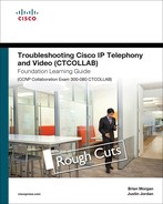
Network architecture, design, and troubleshooting have evolved at an incredible pace over the past couple of decades due to technological advances, new tools, and associated innovations. The single most important contributor is the Open Systems Interconnection (OSI) model. The OSI model was built with modularity in mind. Each layer is dedicated to a particular function. Figure 2-1 shows the OSI model.
The simple model in Figure 2-1 consists of seven layers, including the following:
1. Physical: Deals with physical specifications for conveyance of information across physical media via electrical, optical, or radio transmission (bits).
2. Data Link: Deals with framing and reliable transmission between two directly connected stations. This layer is divided into Media Access Control (MAC) and Logical Link Control (LLC) sublayers (frames).
3. Network: Deals with routing operations within a network or between networks. This includes both routing and routed protocols (packets).
4. Transport: Deals with error correction and flow control to ensure complete data transfer. Transport can be connection-oriented (segments) or connectionless (datagrams).
5. Session: Manages and terminates connections between applications.
6. Presentation: Provides data formatting for applications so that each can understand the information received.
7. Application: Supports end-user processes, services, features, and applications.
This book does not go into an in-depth discussion of the OSI model. We mention it here as a means of dividing and conquering troubleshooting practice. The modularity and interdependence of the layers within the model provide an excellent how-to manual for the troubleshooting process. Start with Layer 1 and work your way up.
Regardless of the troubleshooting activity, the same essential methodologies are needed and documented; they include
• Topology: Up-to-date physical and logical topological maps of the underlying internetwork architecture including Layer 1, Layer 2, and Layer 3 connectivity information.
• Protocols: Detailed information regarding bridged protocols, routed protocols, and routing protocols in use on the internetwork and how those traffic types are prioritized across it (QoS).
• Ingress/Egress: Where does the network touch external networks, and what is the nature of the connection(s)?
• Baseline: Documented expectations/observations of normal network behavior, server memory/CPU/disk utilization, LAN/WAN bandwidth utilization, and so on.
The more information available regarding these topics in electronic, written, or other form, the more quickly issues can be narrowed down and remedied. In the end, there is nothing like knowing your particular deployment in depth. Any discussion of troubleshooting simply must mention two things: documentation and the OSI model. As previously mentioned, collaboration systems are generally seen as being highly complex. The introduction of components from numerous vendors expands the complexity by orders of magnitude. In some so-called collaboration systems, nearly every component is manufactured by a different vendor. In the late 1990s, the big buzzword in causing excessive IT spend was desktop diversity. This was a jab at the whole idea of what was then known as a PC clone. IBM tried to maintain control of the architecture of its personal computer (PC) but failed to do so. As a result, huge numbers of vendors were creating components faster and cheaper than IBM. The endless number of components that could be combined to create a PC was mind-boggling to support from an IT staff perspective. This same concept resonates today in terms of the network and the collaboration system. At the risk of this advice seeming like a marketing plug, using a single vendor for both the network and collaboration system is a definite plus in terms of reducing complexity.
With the convergence of voice, video, and data onto a single, common infrastructure—better known as the converged network—comes a learning curve. Those supporting traditional private branch exchange (PBX) systems are now faced with the need to learn network technologies. Those with server backgrounds also find themselves in the same predicament because OS vendors don’t generally delve deeply into the network or voice realms. In a like manner, those who have been long-time route/switch engineers are faced with learning voice technologies and how they apply to the network in terms of traffic priority. All of these individuals find themselves suddenly dependent on each other for multiple facets of their job responsibilities.
There are a few elements of the collaboration system on which to focus for troubleshooting; they include
• Call Processors: Cisco Unified Communications Manager (CUCM), Cisco Unified Communications Manager Express (CUCME or CME), Cisco Video Communications Server (VCS)
• Applications: CUCM IM&P, Cisco Unity Connection (voice messaging), Cisco Unity Express (CUE), Cisco Unified Contact Center Express (UCCX), Cisco Unified Contact Center Enterprise (UCCE), Cisco Finesse (agent desktop), Cisco MediaSense (call recording)
• Endpoints: IP phones, desktop experience endpoints, Cisco Jabber, immersive TelePresence endpoints, third-party SIP endpoints, and analog endpoints
• Network Infrastructure: LAN/WAN and wireless infrastructure
The effort necessary to troubleshoot any given issue comes with the complexity inherent within the organization (interdepartmental/international politics, and so on), as well as the size and design of the overall infrastructure. Other variables include the number of protocols (both routed and routing) deployed, number of applications involved, manner in which the traffic is prioritized, and number of countries that are encompassed by the system as a whole (dial plan complexity).
Systematic Troubleshooting
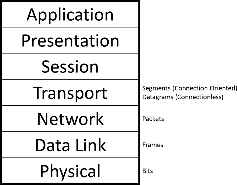
By definition, systematic troubleshooting is a methodology that follows a prescribed model. By following a process, you gain insight and information that will lead more readily to the cause and the resolution of the issue at hand. A troubleshooting model aids in the reduction of a large pool of possibilities down to an immensely narrowed scope or single cause. After a problem is resolved and its root cause identified, thorough documentation of the cause, symptoms, impact, and resolution will aid in training personnel, reducing time to repair should the issue recur, and increase the expertise of the organization at large. Cisco has created a problem-solving model for just this purpose. This model is shown in Figure 2-2.
Figure 2-2. Cisco Problem-Solving Model
The model includes a number of logical steps of the investigation:
Step 1. Define the problem and hypothesize about potential causes based on symptoms observed/reported.
Step 2. Gather facts and information regarding the issue to aid in isolating it. This includes user-reported input, first-hand observation, network tool output, and more. Excluding as many possibilities as possible is a key aspect in narrowing down the actual cause.
Step 3. Based on information gleaned from all sources, consider possible causes.
Step 4. Create a plan of attack aimed at verifying and remedying the most likely causes. The plan should address only one variable or change at a time.
Step 5. Implement the action plan. Again, you should address only one variable or change at a time.
Step 6. Analyze the results to ascertain whether or not the problem has been resolved.
Step 7. If it has not been resolved, return to step 4 and begin the process for the next most likely cause. If your list of possible causes has been exhausted with no resolution, return to step 2 and continue information gathering.
Step 8. If the problem is resolved, document the root cause, symptoms experienced, user impact, and steps that resolved the problem.
Define the Problem
Defining the problem isn’t always easy. The “problem” comes by any number of means—an alert from a management system, a flashing red indicator on a monitoring display, a call from a user. Regardless, it will require varying degrees of definition and/or refinement. There will likely be varying degrees of available information within those reporting methods. For example, an executive may call and simply say, “My computer isn’t working. Fix it!” and hang up the phone, leaving you to figure out exactly which of the myriad definitions for “My computer isn’t working” might be. Whereas another user may call with the same demand but be willing to answer a few clarifying questions, such as “Can you be more specific in what is not working?” or “Is a particular application not working?”
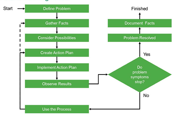
Keep in mind, too, that “not working” may be by design. If the user responds, “I can’t get to Facebook,” the reason may simply be that corporate policy has been implemented to block Facebook from certain VLANs. So, don’t be surprised if defining the problem actually ends up being no problem due to intentional blocking to maintain productivity and limit traffic. Figure 2-3 shows a legitimate situation.
Figure 2-3. Sample Network Problem
Figure 2-3 shows two sites connected via an IP WAN with subscriber nodes on both sides of the WAN. The phone at directory number (DN) 2002 is attempting to call the phone at DN 3002. The call progresses, and 3002 rings. However, when the 3002 phone is answered, the call fails and results in a fast busy signal.
Consider the manner by which the issue was reported. A user may send an instant message (IM) asking if the phones are down or if the network is having problems. Only through a significant amount of research do you arrive at the actual description of the true problem. You have to work your way from “the phone doesn’t work” to “the call fails” on to “I get a busy signal.” At this point, you must ascertain whether it was a busy signal or a fast busy signal. That particular aspect will have a huge impact on the direction of your efforts.
The process of defining the problem can present the following questions:
• What is this person talking about? Need more information. Busy or fast busy? Fast busy.
• What exactly was dialed? 3002.
• Did the call fail while the numbers were being dialed (that is, before the last digit was pressed) or after the numbers were all dialed? After.
• Is this a network problem? Check network monitoring tools. No alerts.
• Were any changes made? Yes. When? Last night. What changed? Region configurations were updated to conserve WAN bandwidth.
This is an exceedingly common issue. It is likely to have happened within a few seconds. These are the kinds of questions and informational pointers that enable you to proceed in the right direction. Continue gathering facts.
Gather the Facts
Fact gathering happens largely in conjunction with defining the problem. You need to know what is happening, how it’s happening, and when it’s happening. When you gain some experience, the entire issue will jump out at you after a couple of questions. Some questions are timeless and relevant to every issue, regardless of how the reports come in. Others are specific to a given situation.
Question to User: When did this first occur?
Answer: I noticed it this morning when I tried to call San Jose.
Question to User: Is it intermittent or recurring? If it’s intermittent, is there a particular pattern to the number dialed, time of day, or other corroborating characteristic?
Answer: Recurring. I can’t dial that number at all.
Question to User: Are there any messages or tones that play? Or does it simply remain silent or disconnect altogether?
Answer: It rings and then goes to a busy signal.
Question to User: Is it a regular busy signal or a faster one?
Answer: Faster.
Question to User: Can you call other numbers, such as the person next to you or your cell phone number?
Answer: Yes. No issues calling anywhere else that I know of.
Question to User: Is anyone else around having the same issue dialing the same number(s)?
Answer: Yes. Everyone I’ve asked in the department seems to have the same issue.
Question to User: Exactly what digits are being dialed? When does the call fail (during or after dialing)?
Answer: 3002. It fails after I dial the whole number.
Question: Does the call work in the opposite direction? Can they call you?
Answer: I’m not sure.
The end users may or may not have answers to these questions. When you have the basics and have an idea of what happened, trace the call flow. If you cannot duplicate the issue from your phone, it may be worthwhile going to the users’ desks and seeing the issue firsthand. In many environments, this is not possible. In that case, having test phones of the model(s) in use by the user community is a great alternative. Clone that user’s phone to a phone in your test bank. Then dial the number exactly as the user is dialing it. Your phone should have the same issue dialing if the problem is related to dial plan or configuration rather than network issues.
When you have a very clear picture, use the dialed number analyzer and other tools to trace the call flow. Make a note of any trunks being traversed, gateways utilized, and site-specific information. If no clear issue comes to mind, enable CUCM debugs/traces and review the output to determine the cause of the call failure. Chapter 3, “Using Troubleshooting and Monitoring Tools,” goes into detail regarding the tools at your disposal. Consider what issues may be in play.
Consider the Possibilities
Through the investigative process to this point, considerable information has been gathered. So, some things can be ruled out. Here is a summary of what we have learned:
1. The call is placed and rings on the far end. When the call is answered, the call drops and a fast busy signal results. This signal rules out a call-routing (calling search space, route pattern lookup, translation patterns, and so on) issue. The dialed number analyzer would also return a valid call route path.
2. A change to the CUCM configuration was made last night in which the regions were reconfigured to better conserve WAN bandwidth between the sites by using a less-bandwidth-intensive codec (G.729a instead of G.711).
3. Everyone in the Dallas office, or at least the same department, is having the same issue but can dial other numbers, both internal and PSTN.
4. The number is not being misdialed. Only 3002 is being dialed.
5. In mapping the call flow, no PSTN gateways or trunks are being traversed. So, the issue is likely internal.
6. You do not have enough information to rule out the network as the cause. But there are no alerts on the network management system and no other reports of latency, lack of reachability, or other diminished capabilities.
7. CUCM debugs and traces indicate errors pointing to a lack of a transcoding resource.
Transcoding is a process that converts media flows between two codec types. In this case, a change was made that was meant to utilize G.711 calls within the same site while using G.729a for site-to-site calls traversing the WAN. The situation is consistent with a codec mismatch. Signaling is not impacted; the call only fails when the media path tries to set up. Now that you’ve found the most likely cause, it’s time to create an action plan.
Create an Action Plan
In creating the plan, it is advisable to break the problem into small steps. Because you have identified the most likely cause, start with the source device. Check its configuration, document it, and then move on to the next element in the call flow. As part of the overall plan, be sure to include checking the network configuration for access lists or other network-related issues that might be blocking media traffic. This task might be that you delegate to a colleague if you lack the time or expertise to check the hop-by-hop network path between the phones in question.
Create a plan to analyze and change only one potential cause at a time. Of course, begin with the most likely one. In this case, the focus is pointing firmly to the region configuration changes made last night. Begin by documenting the region configuration of the phones at the Dallas site followed by the San Jose phones. With the plan in place, set it into motion.
Implement the Action Plan
In building and implementing the action plan, you should keep a common theme in mind: “First, do no harm.” Make sure your plan and action items do not make the issue worse. Additionally, limit the potential impact of the change with regard to other users. Any change to a device pool, for example, may reset all of the phones within it. Finally, minimize the extent or duration of any security lapse. If the issue was caused by an access list, determine what the applied access list was actually supposed to do. Simply removing the access list from the interface or from the configuration is not necessarily a good long-term solution. There may be legitimate traffic-blocking/shaping reasons regarding why that access list was initially put in place.
The region configuration is determined by the device pool. Analyzing the source phone’s configuration shows that it is in the device pool created for Dallas-based devices: dp-dallas-phones. Digging into the device pool shows that it is in the Dallas phone region: reg-dallas-phones. Figure 2-4 shows the region configuration for the Dallas phones.
Figure 2-4. Dallas Phones Region Details

In Figure 2-4, the region configuration for reg-dallas-phones inter-region codec for reg-sanjose-phones is set to Maximum Audio Bit Rate 256 Kbps (L16, AAC-LD). The Maximum Audio Bit Rate should have been set to 8 Kbps (G.729) during the maintenance window. As you see in Figure 2-4, that was not done. This is the source of the issue with the call failures between the sites as the reg-sanjose-phones inter-region codec for reg-dallas-phones is set to 8 Kbps (G.729). Change the Maximum Audio Bit Rate for the inter-region codec to reg-sanjose-phones to the correct setting as shown in Figure 2-5.
Figure 2-5. Dallas Phones Region Corrected Details
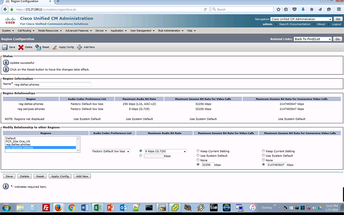
With that change made, it’s time to test the results.
Observe the Results
If you cloned a phone to use in testing, place a call to 3002 to see how it works. If you didn’t clone a phone, get in touch with the user who reported the issue and have that person attempt the call again. If the call sets up properly and there is two-way audio, your change is successful. The results are as expected and the problem is resolved. Document the symptoms, the issue, the changes made, the process by which those changes were decided upon, and how well the solution worked out.
If the issue still persists, it’s time to go back to the drawing board to figure out what is causing the issue now that the most likely culprit has been ruled out.
Restart the Process
If, after you observe the results, the issue still occurs, there is a larger underlying issue to be explored. Obviously, the region configuration was incorrect and may have contributed to the overall issue. But if it’s still not working properly, there are additional aspects to explore, such as access lists (if not already covered), RTP Header Compression settings bidirectionally, WAN considerations (provider limits on per-call bandwidth), and so on. Return to the Create Action Plan step and go back through the process until the issue is resolved.
Document the Facts
Documentation has long been the most reviled word within the IT realm. The reason is not so much that it is difficult to create. It tends to be difficult to maintain because someone has either procrastinated, forgotten, or ignored making updates.
The details of the issue, symptoms observed, steps taken, and ultimate result of the steps should be well documented. The details regarding the things that didn’t work may be just as valuable. A well-documented solution should include what did and did not work for a given issue.
Some people say that the only thing more rare than updated documentation is someone actually going back to read it. Regardless, it is good to keep problem/symptom/solution documents for future technicians.
Chapter Summary
The more information available, the faster a resolution can be implemented. Problems will land in your help desk queue from a number of potential directions. Remember to remain calm and ask the right questions for a given situation. From a user standpoint, something is simply not working. Users do not have to understand how to solve the issues. Your job is to figure out how to make it work, keep it working, and fix it when it’s not working
Use the tools available to you. Chapter 3, “Using Troubleshooting and Monitoring Tools,” introduces and explains how to use those tools. Gather as many facts as possible to indicate a root cause and rule out other potential ones. Isolate the issue and build a plan on how to remedy it. Then implement that plan and test it. If it works, great! If it doesn’t, go back into fact-gathering or action-planning mode. Keep working through the process until the issue is resolved. After it is fixed, document it. Include what worked as well as what didn’t work. The more information you can gather on individual issues, the more you learn and the faster future iterations of that issue (and ones like it) can be remedied.
References
For additional information, refer to the following:
Troubleshooting Methodology on CCO:
http://www.cisco.com/en/US/docs/internetworking/troubleshooting/guide/tr1901.html
Review Questions
Use these questions to review what you’ve learned in this chapter. The answers appear in Appendix A, “Answers to Chapter Review Questions.”
1. Which layer of the OSI model deals with framing?
a. Physical
b. Data Link
c. Network
d. Transport
2. Which layer of the OSI model deals with both connection-oriented and connectionless traffic?
a. Physical
b. Data Link
c. Network
d. Transport
3. Which is an example of an application in a collaboration system?
a. Conference Bridge
b. Transport Layer
c. MediaSense
d. TelePresence
4. What is the first step in the Cisco problem-solving model?
a. Define the Problem
b. Gather Facts
c. Document Facts
d. Observe Results
5. What is the final step in the Cisco problem-solving model?
a. Define the Problem
b. Gather Facts
c. Document Facts
d. Observe Results
6. Which is part of the Create Action Plan step in the Cisco problem-solving model?
a. Don’t make it worse.
b. Break the problem into small steps.
c. Gather information.
d. Define the problem.