Chapter 5
Firepower System Virtual on VMware
In the previous chapters, you have learned how to install the Firepower System software on Cisco hardware. If you choose not to purchase any additional hardware, you can still deploy the Firepower System in your existing virtual infrastructure. You can choose to virtualize both or one of the Firepower appliances—either the Firepower Management Center (FMC) or Firepower Threat Defense (FTD). This chapter discusses the implementation of FMC Virtual and FTD Virtual in VMware—one of the most popular virtual environments.
FMC and FTD Virtual Essentials
An FMC virtual appliance can manage any FTD physical appliance. Similarly, an FTD virtual appliance is fully interoperable with an FMC virtual appliance as well as FMC physical hardware. Before deploying a Firepower virtual appliance, let’s take a moment to look at the key deployment options.
Supported Virtual Environments
Beginning with Version 6.1, the Firepower software supports a wide variety of virtual environments, such as VMware, Kernel-based Virtual Machine (KVM), and Amazon Web Services (AWS). This chapter uses VMware to demonstrate the deployment of a Firepower virtual appliance.
Table 5-1 provides a list of virtual environments that are compatible with Firepower Version 6.1.
Table 5-1 Virtual Environments for Firepower Version 6.1
Virtual Environment |
Supported Platform |
VMware |
ESXi 5.5, 6.0 |
Amazon Web Services (AWS) |
Virtual Private Cloud (VPC), Elastic Compute Cloud (EC2) |
KVM |
Tested on Ubuntu 14.04 LTS |
Note
The Firepower software Version 6.1 does not support Microsoft virtualization platforms. The support of Azure begins from the Firepower software Version 6.2 or greater.
To manage a virtual appliance on a VMware ESXi server, you can use vCloud Director, vCenter, or vSphere Client. vSphere Client has two different variations—web and desktop—both of which are supported by the Firepower virtual appliances.
To host a Firepower virtual appliance, you can use VMware ESXi 5.5 and 6.0, but the following solutions are unsupported:
![]() VMware Workstation
VMware Workstation
![]() VMware Server
VMware Server
![]() VMware Player
VMware Player
![]() VMware Fusion
VMware Fusion
ESXi Versus VI
The tarball (.tar.gz file) of a Firepower virtual appliance includes templates for ESXi or the virtual infrastructure (VI). The key difference between them is the initial setup process, which includes configuring the network, setting up a password for the admin account, and so on.
In a VI template deployment, you configure the initial system settings by using a deployment wizard, before a Firepower virtual software is deployed. In an ESXi template, however, you configure the initial settings from the VMware console after an appliance is deployed.
The examples in this chapter use the ESXi OVF template to deploy a Firepower virtual appliance on VMware.
VMware Installation Package in a Tarball
The VMware installation package for Firepower virtual appliance comes in a .tar.gz file format, which includes three different types of files:
![]() Open Virtual Format (.ovf) file: An XML file that stores references to many elements of a Firepower System installation package
Open Virtual Format (.ovf) file: An XML file that stores references to many elements of a Firepower System installation package
![]() Virtual Machine Disk (.vmdk) file: A compressed virtual disk that stores the Firepower System software
Virtual Machine Disk (.vmdk) file: A compressed virtual disk that stores the Firepower System software
![]() Manifest (.mf) file: A clear-text file that stores the SHA1 digests of any OVF and VMDK files in a package
Manifest (.mf) file: A clear-text file that stores the SHA1 digests of any OVF and VMDK files in a package
Figure 5-1 shows the files that are packaged in a tarball for a Firepower virtual appliance Version 6.1.

Disk Provisioning Options
During the deployment of a Firepower virtual appliance, you can choose one of the following options for provisioning your virtual disk:
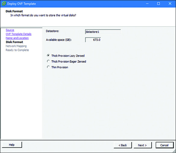
![]() Thick Provision Lazy Zeroed: Space for a virtual disk is allocated during its creation but zeroed out later.
Thick Provision Lazy Zeroed: Space for a virtual disk is allocated during its creation but zeroed out later.
![]() Thick Provision Eager Zeroed: The space allocation and zeroing out of the data are performed at the time of virtual disk creation. Therefore, this method might take more time.
Thick Provision Eager Zeroed: The space allocation and zeroing out of the data are performed at the time of virtual disk creation. Therefore, this method might take more time.
![]() Thin Provision: Disk space is allocated on an on-demand basis. The size of a virtual disk grows whenever there is a need, up to the maximum allocated limit.
Thin Provision: Disk space is allocated on an on-demand basis. The size of a virtual disk grows whenever there is a need, up to the maximum allocated limit.
Figure 5-2 shows these three options for provisioning a virtual disk on an ESXi host using the vSphere Client software. The examples in this book use the Thick Provision Lazy Zeroed option.

Best Practices for Firepower Virtual Appliance Deployment
If you plan to deploy FMC Virtual and FTD Virtual Version 6.1, the FMC must be running Version 6.1 or greater. This chapter describes the process of reimaging the FMC to Version 6.1.
Pre-deployment Best Practices
Consider the following best practices before you deploy a Firepower virtual appliance:
![]() Depending on the hardware resources of a server, the process of deploying a new Firepower virtual appliance may take about an hour. You should plan for additional time to fulfill any prerequisites and post-deployment setup.
Depending on the hardware resources of a server, the process of deploying a new Firepower virtual appliance may take about an hour. You should plan for additional time to fulfill any prerequisites and post-deployment setup.
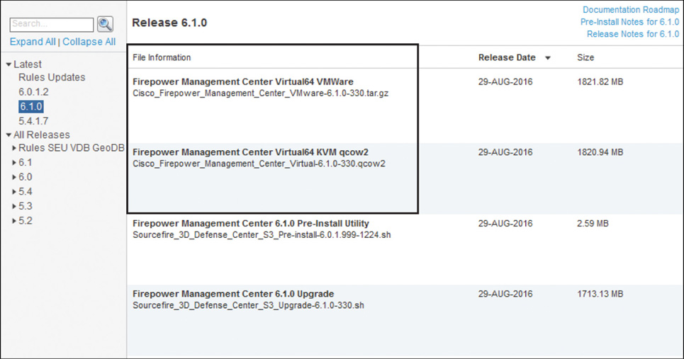
![]() Using an ISO file to build a Firepower appliance in a virtual environment is not supported. If your virtual network is based on VMware, use the Open Virtualization Format (OVF) file, which is compressed into a .tar.gz file. If your infrastructure is KVM-based, use the QEMU Copy On Write (.qcow2) file. Figure 5-3 shows a.tar.gz file and a .qcow2 file that are packaged for VMware and KVM, respectively. You can download them from the Cisco Software Download page.
Using an ISO file to build a Firepower appliance in a virtual environment is not supported. If your virtual network is based on VMware, use the Open Virtualization Format (OVF) file, which is compressed into a .tar.gz file. If your infrastructure is KVM-based, use the QEMU Copy On Write (.qcow2) file. Figure 5-3 shows a.tar.gz file and a .qcow2 file that are packaged for VMware and KVM, respectively. You can download them from the Cisco Software Download page.
![]() After you download an appropriate file for a Firepower virtual appliance from cisco.com, always verify the MD5 or SHA512 checksum of the files you have downloaded to confirm that the file is not corrupt and has not been modified during download. Figure 5-4 shows how the MD5 and SHA512 checksum values for the FTD Virtual installation package are displayed at cisco.com when you hover your mouse over a filename.
After you download an appropriate file for a Firepower virtual appliance from cisco.com, always verify the MD5 or SHA512 checksum of the files you have downloaded to confirm that the file is not corrupt and has not been modified during download. Figure 5-4 shows how the MD5 and SHA512 checksum values for the FTD Virtual installation package are displayed at cisco.com when you hover your mouse over a filename.

Inside a tarball, you will find a manifest file (*.mf) that stores the individual SHA1 checksum values of the *.vmdk and *.ovf files in a tarball.
![]() Read the release notes to determine any known issues, any special requirements, and any instructions before you begin reimaging or performing a system restoration.
Read the release notes to determine any known issues, any special requirements, and any instructions before you begin reimaging or performing a system restoration.
![]() Never power off a virtual appliance when the deployment or initialization is in progress. Upon a successful initialization, you will find a Firepower login prompt at the VMware console.
Never power off a virtual appliance when the deployment or initialization is in progress. Upon a successful initialization, you will find a Firepower login prompt at the VMware console.
Post-deployment Best Practices
Consider the following best practices after you deploy a Firepower virtual appliance:
![]() If your ESXi server has unused resources, you can allocate them to your Firepower virtual appliance. Allocating additional resources can enhance system performance. However, reducing any resources from the minimum requirement is unsupported. You can find the minimum requirements in the “Fulfilling Prerequisites” section, later in this chapter.
If your ESXi server has unused resources, you can allocate them to your Firepower virtual appliance. Allocating additional resources can enhance system performance. However, reducing any resources from the minimum requirement is unsupported. You can find the minimum requirements in the “Fulfilling Prerequisites” section, later in this chapter.
![]() You can replace the E1000 network adapters with the VMXNET3 adapters for higher throughput.
You can replace the E1000 network adapters with the VMXNET3 adapters for higher throughput.
Tip
The steps to upgrade a default E1000 adapter with a VMXNET3 adapter are described in the “Verification and Troubleshooting Tools” section, later in this chapter.
![]() As a part of the disaster recovery plan, you should periodically make a backup of the existing events and configurations. Do not use any VMware-provided built-in features to make a backup of a Firepower virtual appliance. Instead, use the FMC’s Backup/Restore tool. Figure 5-5 shows the FMC Backup Management page. It is located at System > Tools > Backup/Restore.
As a part of the disaster recovery plan, you should periodically make a backup of the existing events and configurations. Do not use any VMware-provided built-in features to make a backup of a Firepower virtual appliance. Instead, use the FMC’s Backup/Restore tool. Figure 5-5 shows the FMC Backup Management page. It is located at System > Tools > Backup/Restore.
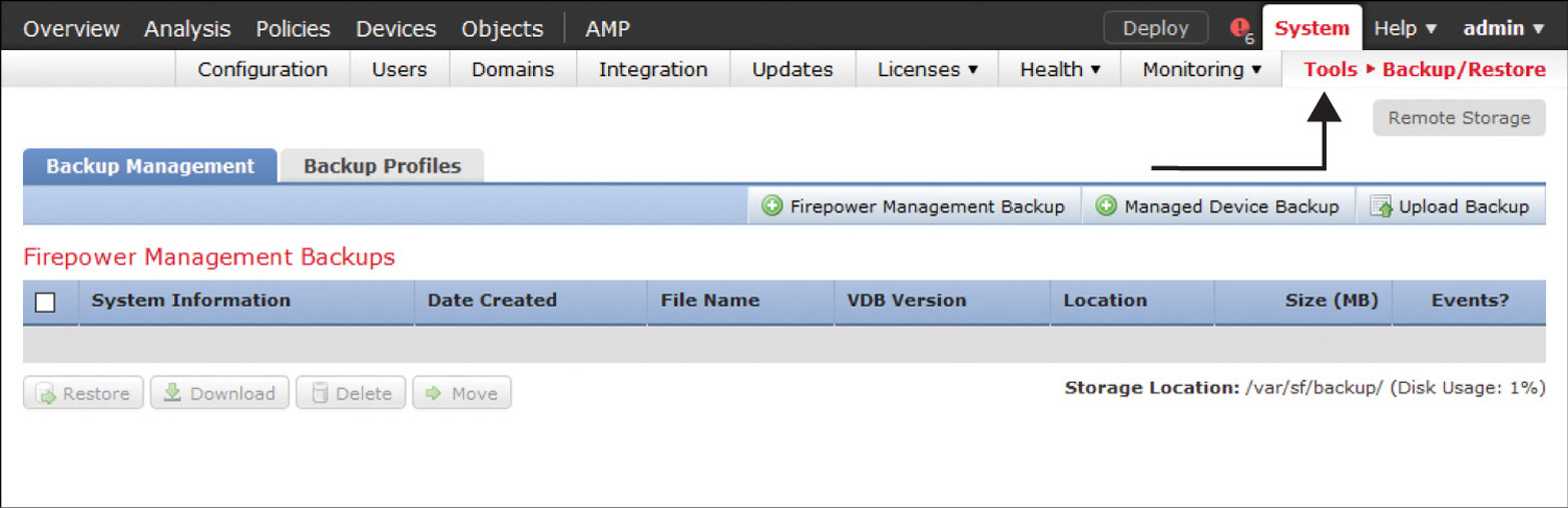
Table 5-2 shows some of the backup tools provided by VMware. The Firepower virtual appliances do not support these tools.
Table 5-2 VMware Backup and Migration Tools (Not Supported by Firepower)
Feature |
VMware Purpose |
vMotion |
Migration of a running virtual machine from one physical server to another, without any downtime |
Cloning |
Duplication of a virtual machine with the same configurations and applications |
Snapshot |
Saving of any particular state of a virtual machine |
![]() You can also use the Import/Export tool in the FMC to copy a policy. During an import, the versions of a restored system must match with the FMC from which any policies were originally exported. Therefore, when you export, you must remember the software and Rule Update version information of the original FMC. Figure 5-6 shows the Import/Export page, which is located at System > Tools > Import/Export.
You can also use the Import/Export tool in the FMC to copy a policy. During an import, the versions of a restored system must match with the FMC from which any policies were originally exported. Therefore, when you export, you must remember the software and Rule Update version information of the original FMC. Figure 5-6 shows the Import/Export page, which is located at System > Tools > Import/Export.

Installing and Configuring a Firepower Virtual Appliance
Deployment of a Firepower virtual appliance in VMware is not a one-click process. After you download a tarball for Firepower software from cisco.com and extract it onto your desktop, you need to complete the following steps:
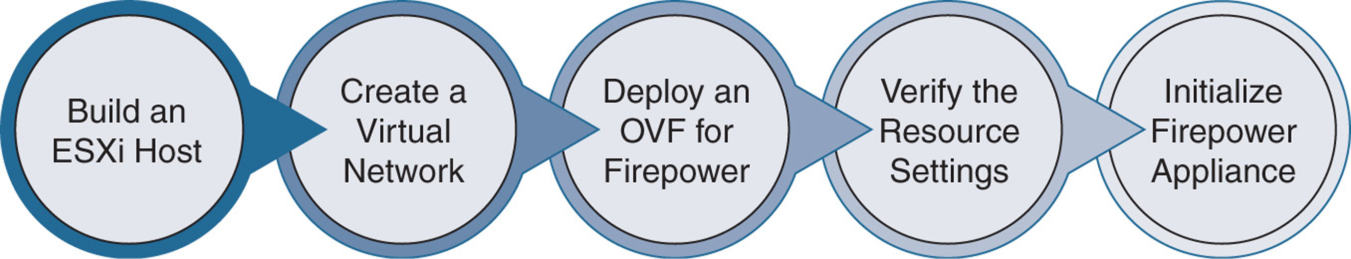
Step 1. Build an ESXi host that is compatible with Firepower.
Step 2. Build a virtual Layer 2 network on the ESXi host.
Step 3. Deploy the OVF file for the desired Firepower appliance.
Step 4. Verify the resource allocation and network mapping.
Step 5. Power on the Firepower appliance and initialize it.
Figure 5-7 shows the key steps in deploying a Firepower virtual appliance on a VMware ESXi host.
Fulfilling Prerequisites
You must fulfill the following requirements before you install a Firepower virtual appliance:
![]() To deploy any Firepower software, your server must have a 64-bit CPU that supports the virtualization technology.
To deploy any Firepower software, your server must have a 64-bit CPU that supports the virtualization technology.
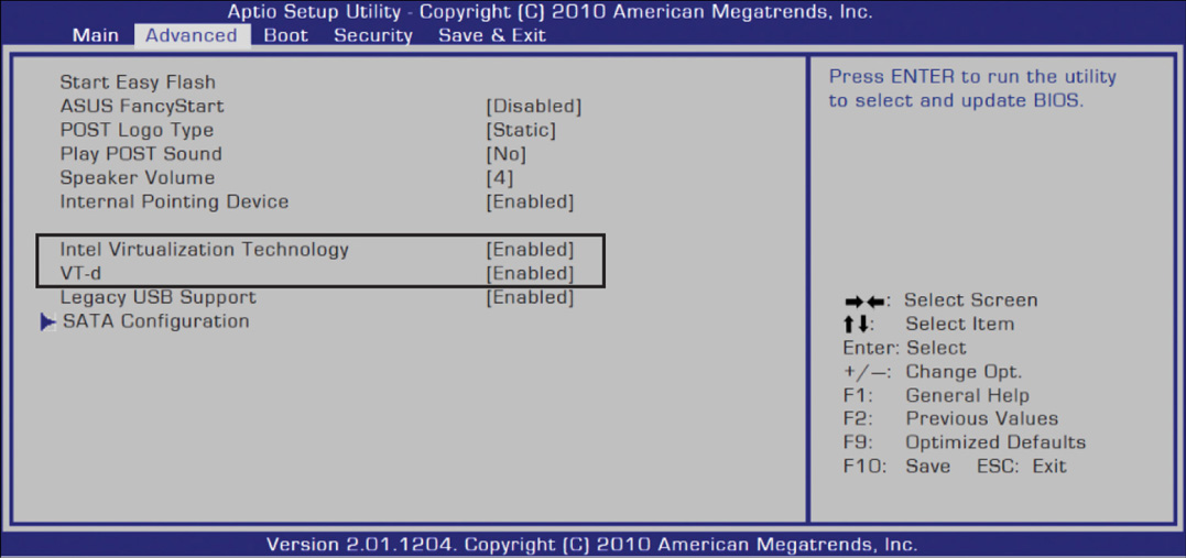
![]() You must enable the virtualization functionality from the BIOS setup utility.
You must enable the virtualization functionality from the BIOS setup utility.
Figure 5-8 shows Intel Virtualization Technology enabled in the BIOS setup utility. Depending on the hardware vendor of an ESXi server, a setup utility may look different from this.
![]() After you build an ESXi host, connect to the host by using vSphere Client. You can use either a web client or a desktop client.
After you build an ESXi host, connect to the host by using vSphere Client. You can use either a web client or a desktop client.
Figure 5-9 shows the default home page of an ESXi host. To view this page, enter the IP address of your ESXi server into a browser. This page provides you with a link to download the vSphere Client software.

![]() Whether your ESXi host runs Version 5.5 or Version 6.0, ensure that your Firepower virtual appliance is allocated the minimum amount of resources. Do not reduce the settings from the minimum requirements. Table 5-3 shows the minimum requirements for a Firepower virtual appliance.
Whether your ESXi host runs Version 5.5 or Version 6.0, ensure that your Firepower virtual appliance is allocated the minimum amount of resources. Do not reduce the settings from the minimum requirements. Table 5-3 shows the minimum requirements for a Firepower virtual appliance.
Table 5-3 Minimum Resource Allocation for a Firepower Virtual Appliance
Resource Type |
FMC |
FTD |
CPU |
Four |
Four |
Memory |
8 GB |
8 GB |
Disk space |
250 GB |
48.25 GB |
Network interface |
One |
Four |
Read the “Verification and Troubleshooting Tools” section, later in this chapter, to learn how to add an additional resource.
Creating a Virtual Network
Let’s say that you have just built an ESXi host. Now you want to deploy both of the Firepower virtual appliances—an FMC virtual appliance and an FTD virtual appliance. You need to create a Layer 2 virtual topology using vSwitch and VMware network adapter.
Figure 5-10 shows a topology created inside a virtual network. An ESXi host, FMC, and FTD are connected to a management network, and data from inside the network can traverse to the Internet. All the servers are placed in a DMZ network.

The number of steps to create a virtual topology could be different, depending on the number of required interfaces on a particular appliance you want to deploy. For example, by default, FMC Virtual requires only one interface for management communication, whereas FTD Virtual requires four interfaces—one interface for management communication and three interfaces for traffic inspection.
In the next few pages, you will learn how to create the virtual network shown in Figure 5-10 on a VMware ESXi host, using vSphere Client software.
Creating a Network for FMC Virtual
By default, a virtual switch is created on a new ESXi installation. To view a virtual switch, go to Configuration > Networking in vSphere Client.
Figure 5-11 shows a default virtual switch vSwitch0 that is created by the ESXi host. A physical adapter vmnic0 is connected with two default virtual ports: Management Network and VM Network.

The Management Network port is automatically mapped with the management interface of the ESXi host. The VM Network port is available for use. You can use it as the management interface for your FMC virtual appliance. To make it clear and meaningful, you could optionally rename the default labels by following these steps:
Step 1. Click the Properties option next to Standard Switch: vSwitch0. The vSwitch0 Properties window appears. Figure 5-12 shows two virtual ports created by the ESXi host during installation.

Step 2. Select the VM Network port and click the Edit button. The VM Network Properties windows appears, as shown in Figure 5-13. This is where you can edit the default port VM Network.

Step 3. Change Network Label from VM Network to FMC Management and click OK.
Step 4. Optionally, select the Management Network port, click the Edit button, and then change Network Label from Management Network to VMware Management and click OK.
Figure 5-14 shows the vSwitch0 Properties window with both of the ports renamed. From the new labels, it is now easy to see the purpose of each port.
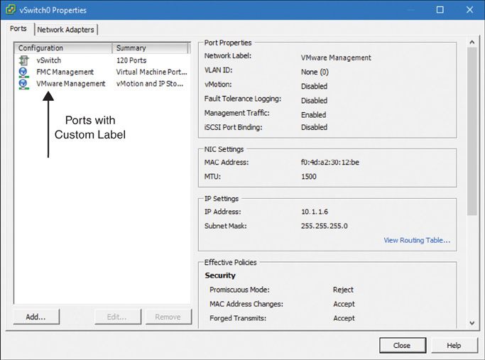
Step 5. Click Close to return to the Networking view, where you can find the newly labeled virtual ports connected to the same physical adapter.
If you plan to deploy FTD Virtual, read the next section. Otherwise, proceed to the section “Deploying an OVF Template.”
Creating a Network for FTD Virtual
Earlier in this chapter, in the section “Fulfilling Prerequisites,” you learned that an FTD virtual appliance requires at least four interfaces—one interface for management traffic and three interfaces for data traffic. Now you can follow these steps to add a network adapter for a virtual appliance:
Note
FTD Virtual can support up to 10 interfaces in total.
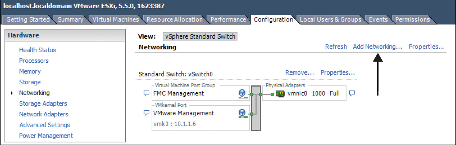
Step 1. Go to the Configuration > Networking page in vSphere Client.
Step 2. Select the Add Networking option, as shown in Figure 5-15. (In this window, you can also see the new labels of the default virtual ports that you renamed in the previous section. Both of them are connected to the vmnic0 physical adapter.) The Add Network Wizard window appears.
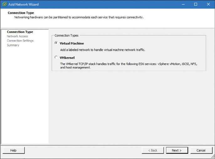
Step 3. Select Virtual Machine as the connection type, as shown in Figure 5-16.
Step 4. Select an existing virtual switch (vSwitch) or create a new one that can map a physical adapter with a virtual port. You can configure each vSwitch to represent a segregated virtual network. Figure 5-17 shows that vmnic0 is mapped with vSwitch0, which connects the FTD Virtual management port.
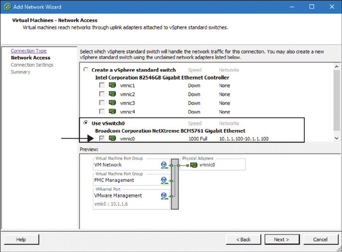
Step 5. Replace the default Network Label setting with a meaningful name (see Figure 5-18). Note that this window allows you to preview the mapping of a virtual port with a physical adapter.

Step 6. Click Next to view a summary. Click Finish to complete the configuration of the vSwitch port group for the FTD Management network.
Step 7. Repeat Steps 1–6 at least three more times to create the remaining three vSwitches that are mandatory on an FTD virtual appliance.
Table 5-4 shows the mapping between the virtual ports and physical adapters that is used in the configuration example of this chapter.
Table 5-4 Mapping Between the Virtual Ports and Physical Adapters
Virtual Port |
Physical Adapter |
Purpose |
FTD Management |
vmnic0 |
For management traffic |
Inside Network |
vmnic1 |
For internal network |
Outside Network |
vmnic2 |
Toward the outside world |
DMZ Network |
vmnic3 |
Network for the server farm |
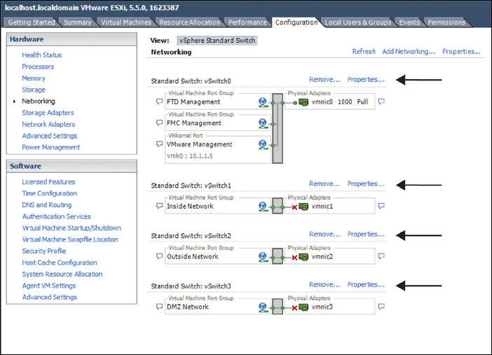
Figure 5-19 shows the final view of the networking configuration page after you create four virtual ports and map them with four individual physical adapters. Each vSwitch can be configured separately by using the Properties option.
Using Promiscuous Mode
Promiscuous mode allows a vSwitch to see any frames that traverse it. It allows an interface to see any packet in a network segment—even the packets that are not aimed for that interface. By default, this mode is disabled on a vSwitch. You must enable this mode on all the virtual ports of an FTD virtual appliance.
The following steps describe how to enable promiscuous mode on the management interface of an FTD virtual appliance. You can also use these steps to enable promiscuous mode on any data interfaces:
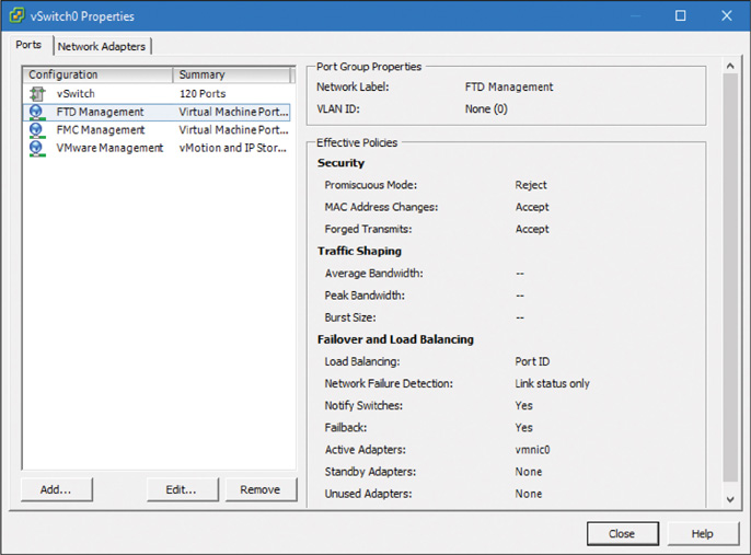
Step 1. Select the Properties option next to vSwitch0. The vSwitch0 Properties window appears, as shown in Figure 5-20. (In this window, you can select any virtual port to find the Promiscuous Mode status, which is Reject, by default.)
Step 2. Select the port on which you want to enable promiscuous mode and click Edit. The Properties window appears.
Step 3. Select the Security tab. All the options, including the Promiscuous Mode option, are unchecked by default.
Step 4. Check all the boxes and select Accept from each dropdown, as shown in Figure 5-21.

Step 5. When you are done, click OK to return to the vSwitch Properties window. Click the Close button to complete the configuration.
Step 6. Repeat Steps 1–5 for all the interfaces on an FTD virtual appliance.
Caution
Enabling all the above options on all the FTD interfaces is a requirement. Failure to enable any single option on a single FTD interface can lead to an unexpected technical issue.
Deploying an OVF Template
After building a Layer 2 topology in VMware, the next step is to deploy an OVF template file in an ESXi host. Use the following steps to deploy an OVF file:
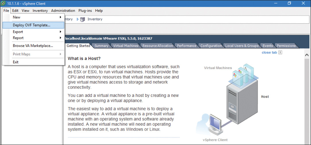
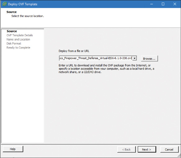
Step 1. In vSphere Client, from the File menu, select the Deploy OVF Template option (see Figure 5-22). The Deploy OVF Template window appears.
Step 2. Click Browse and choose an appropriate OVF file for your virtual appliance. (Figure 5-23 shows the Cisco_Firepower_Threat_Defense_Virtual-ESXi-6.1.0-330.ovf file selected for deployment.) Click Next to continue.
Note
If you want to deploy FMC Version 6.1 on an ESXi host, select the Cisco_Firepower_Management_Center_Virtual_VMware-ESXi-6.1.0-330.ovf file. Similarly, to deploy FTD Version 6.1, select the Cisco_Firepower_Threat_Defense_Virtual-ESXi-6.1.0-330.ovf file.
Step 3. Verify that all the information in the OVF Template Details window is correct (see Figure 5-24). If everything looks good, click Next to continue.

Step 4. Specify a unique name for your virtual appliance. Figure 5-25 shows the custom name FTD for the virtual appliance. Keep in mind that this name must be unique within the inventory. Click Next.

Step 5. Select a disk format type for the virtual disk, such as the Thick Provisioned Lazy Zeroed (as shown in Figure 5-26), and click Next.
Tip
Refer to the section “Disk Provisioning Options,” earlier in this chapter, to learn about different types of disk formats.
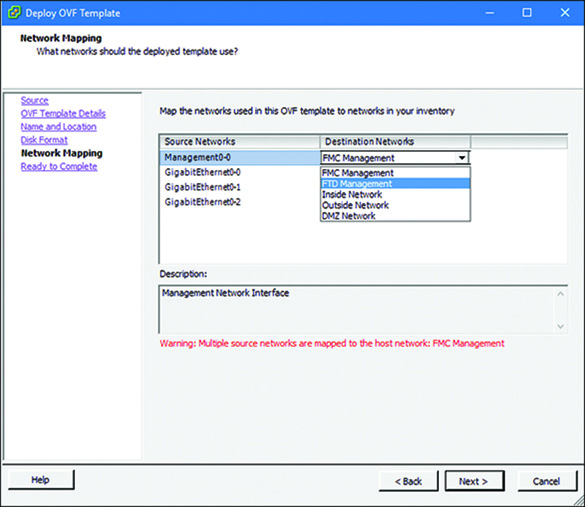
Step 6. In the Network Mapping window, shown in Figure 5-27, map the destination networks (virtual ports) with the source networks (interfaces on a virtual appliance). Use the dropdown to find an appropriate interface. Figure 5-27 shows the selection of the FTD Management virtual port for the management interface of an FTD virtual appliance.
Note
The number of networks you need to map depends on the type of virtual appliance. Remember that an FMC virtual appliance must have at least one interface, and an FTD virtual appliance must have at least four interfaces.
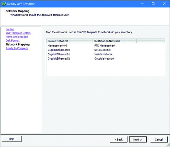
Figure 5-28 shows all the interfaces on an FTD virtual appliance after they are mapped with separate virtual ports.
Step 7. When you finish mapping the network, click Next. A summary of all the settings is displayed, as shown in Figure 5-29. If everything looks good, click Finish to complete the configuration.
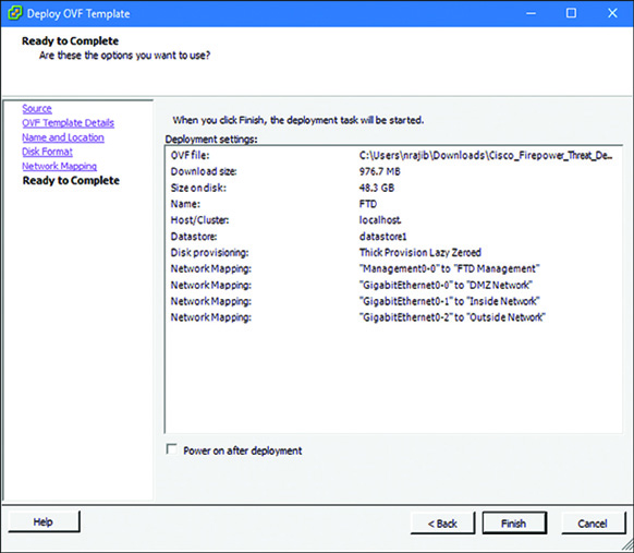
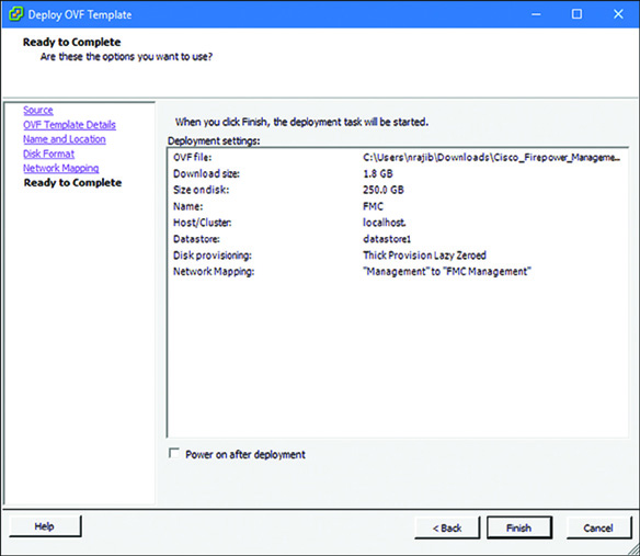
Figure 5-30 shows an example of the pre-deployment settings of an FMC virtual appliance. A screenshot of the Ready to Complete window is provided here, so that you can compare Figure 5-30 (FMC Virtual deployment) with Figure 5-29 (FTD Virtual deployment). You can confirm that FMC allocates more spaces on disk and requires only one interface for management connection.
The deployment begins. The time it takes to complete a deployment depends on various factors, such as the type of Firepower virtual appliance you are deploying, the amount of resources available in the ESXi host, and the connection speed between the ESXi server and the endpoint where the OVF file is stored. Once complete, a confirmation message appears in a Deployment Completed Successfully window, as shown in Figure 5-31.
Initializing an Appliance
Use the following process to begin the initialization of any Firepower virtual appliances (either FMC or FTD):
Step 1. Select the desired virtual appliance from the inventory, as shown in Figure 5-32.
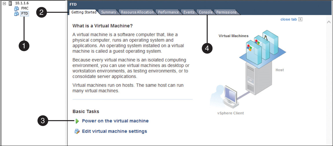
Step 2. Go to the Getting Started tab.
Step 3. Click the Power On the Virtual Machine option.
Step 4. When the initialization begins, view the status in the Console tab.
Initializing an FMC Virtual Appliance
On an FMC virtual appliance, the initialization process ends automatically after 40 to 50 minutes. You can view the status on the Console tab. At the end of the process, a login prompt appears.
Example 5-1 shows the completion of the Firepower software initialization on VMware. As you can see, you can enter the CLI by using the default credentials—username admin and password Admin123.
Example 5-1 Login Prompt for an FMC Virtual Appliance After Initialization Completion
Cisco Firepower Management Center for VMWare v6.1.0 (build 330)
Oct 18 13:20:23 firepower SF-IMS[616]: [616] init script:system [INFO] pmmon
Starting the Process Manager...
Oct 18 13:20:23 firepower SF-IMS[617]: [617] pm:pm [INFO] Using model number
66ESad7: WRITE SAME failed. Manually zeroing.
Cisco Firepower Management Center for VMWare v6.1.0 (build 330)
Firepower login:admin
Password:Admin123
Copyright 2004-2016, Cisco and/or its affiliates. All rights reserved.
Cisco is a registered trademark of Cisco Systems, Inc.
All other trademarks are property of their respective owners.
Cisco Fire Linux OS v6.1.0 (build 37)
Cisco Firepower Management Center for VMWare v6.1.0 (build 330)
admin@firepower:~$
Initializing an FTD Virtual Appliance
On an FTD virtual appliance, the initialization process ends in approximately 20 minutes. At the end of the process, a login prompt appears. You can enter the CLI by using the default credentials—username admin and password Admin123.
Example 5-2 shows the initialization process for an FTD virtual appliance on VMware. The process prompts you to accept the end user license agreement (EULA) and configure the network before a login prompt appears.
Example 5-2 Accepting the EULA and Configuring the Network to Get to the CLI Prompt of an FTD Virtual
Cisco Firepower Threat Defense for VMWare v6.1.0 (build 330)
Firepower login:admin
Password:Admin123
You must accept the EULA to continue.
Press <ENTER> to display the EULA:
.
.
Output Omitted
.
.
Please enter 'YES' or press <ENTER> to AGREE to the EULA:
System initialization in progress. Please stand by.
You must change the password for 'admin' to continue.
Enter new password:
Confirm new password:
You must configure the network to continue.
You must configure at least one of IPv4 or IPv6.
Do you want to configure IPv4? (y/n) [y]:
Do you want to configure IPv6? (y/n) [n]:
Configure IPv4 via DHCP or manually? (dhcp/manual) [manual]:
Enter an IPv4 address for the management interface [192.168.45.45]: 10.1.1.21
Enter an IPv4 netmask for the management interface [255.255.255.0]:
Enter the IPv4 default gateway for the management interface [192.168.45.1]: 10.1.1.1
Enter a fully qualified hostname for this system [firepower]:
Enter a comma-separated list of DNS servers or 'none' []: none
Enter a comma-separated list of search domains or 'none' []: none
If your networking information has changed, you will need to reconnect.
For HTTP Proxy configuration, run 'configure network http-proxy'
Configure firewall mode? (routed/transparent) [routed]:
Configuring firewall mode ...
Update policy deployment information
- add device configuration
- add network discovery
- add system policy
You can register the sensor to a Firepower Management Center and use the
Firepower Management Center to manage it. Note that registering the sensor
to a Firepower Management Center disables on-sensor Firepower Services
management capabilities.
When registering the sensor to a Firepower Management Center, a unique
alphanumeric registration key is always required. In most cases, to register
a sensor to a Firepower Management Center, you must provide the hostname or
the IP address along with the registration key.
'
configure manager add [hostname | ip address ] [registration key ]'
However, if the sensor and the Firepower Management Center are separated by a
NAT device, you must enter a unique NAT ID, along with the unique registration
key.
'
configure manager add DONTRESOLVE [registration key ] [ NAT ID ]'
Later, using the web interface on the Firepower Management Center, you must
use the same registration key and, if necessary, the same NAT ID when you add
this sensor to the Firepower Management Center.
>
The > prompt at the end of Example 5-2 confirms that the installation is totally complete.
The next step is to verify the network connectivity on the management interface and then begin the registration process. (Chapter 6, “The Firepower Management Network,” explains the management connection, and Chapter 7, “Firepower Licensing and Registration,” describes the registration process.)
Verification and Troubleshooting Tools
In this section, you will learn how to investigate some common issues with Firepower virtual appliances. If you experience any issues with the ESXi host operating system, you should find a troubleshooting guide at the VMware website and read it.
Determining the Status of Allocated Resources
The amount of resources allocated to a Firepower virtual appliance is very critical for its system performance. You can verify resource allocation in two different places in vSphere Center:
![]() Summary page: The Summary page of a virtual appliance provides an overview of the deployed OVF template and its allocated resources. Figure 5-33 shows the allocated CPU, memory, storage, and so on for an FMC virtual appliance.
Summary page: The Summary page of a virtual appliance provides an overview of the deployed OVF template and its allocated resources. Figure 5-33 shows the allocated CPU, memory, storage, and so on for an FMC virtual appliance.

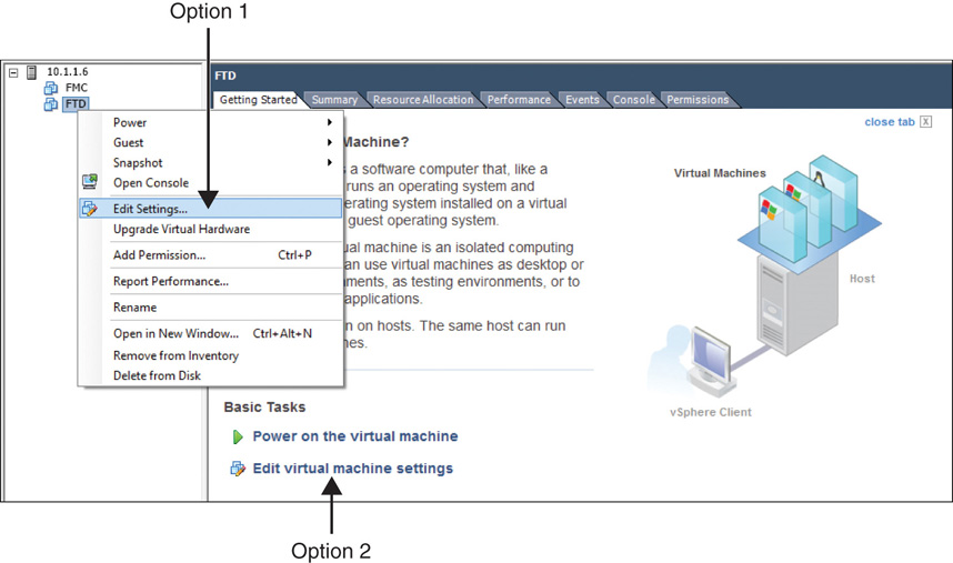
![]() Virtual machine settings editor: This editor allows you to view, add, or remove resources allocated to a virtual machine. There are two ways to navigate to the virtual machine settings editor (see Figure 5-34):
Virtual machine settings editor: This editor allows you to view, add, or remove resources allocated to a virtual machine. There are two ways to navigate to the virtual machine settings editor (see Figure 5-34):
![]() Option 1: Right-click the name of a virtual appliance from the inventory list and select the Edit Settings option. The Virtual Machine Properties window appears.
Option 1: Right-click the name of a virtual appliance from the inventory list and select the Edit Settings option. The Virtual Machine Properties window appears.
![]() Option 2: Go to the Getting Started page and click on the Edit Virtual Machine Settings option under Basic Tasks. The Virtual Machine Properties window appears.
Option 2: Go to the Getting Started page and click on the Edit Virtual Machine Settings option under Basic Tasks. The Virtual Machine Properties window appears.
Determining the Status of a Network Adapter
If the management interface or data interface on a Firepower virtual appliance does not show up or stays always down, you need to verify the network adapter configuration of that virtual appliance. To verify an adapter using vSphere Client, follow these steps:
Step 1. From the inventory list, select the virtual appliance that does not display an interface properly.
Step 2. Open the Virtual Machine Properties window for a virtual machine, using one of the two options described in the previous section.
Step 3. From the Hardware list, select the network adapter that is not functioning properly, as shown in Figure 5-35.
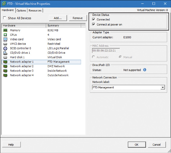
Step 4. Under Device Status on the right side of the window, make sure both options—Connected and Connect at Power On—are checked. Figure 5-35 shows the status of the FTD management interface. It is currently connected, and it is configured to be connected when the FTD virtual appliance is powered on.
If you are still experiencing an issue with a network adapter, did you complete all the steps when you enabled promiscuous mode? Go back to the windows shown in Figure 5-20 and Figure 5-21 and verify whether your vSwitch properties match the settings shown in those images.
Upgrading a Network Adapter
When you deploy a virtual appliance, VMware uses the E1000 network adapter by default. You can also choose a VMXNET3 adapter for your Firepower virtual appliance. The difference between an E1000 adapter and a VMXNET3 adapter is in throughput. The throughput of a VMXNET3 adapter is 10 Gbps, whereas an E1000 adapter supports up to 1 Gbps.
On any given virtual appliance, all the adapters have to be the same type. In other words, if you want to upgrade the type of an adapter, you must upgrade it for all the interfaces on any single virtual interface. It is, however, not a requirement to have the same type of network adapters on all the virtual appliances in any network. For example, if the management interface of an FMC virtual appliance is an E1000 adapter, it should be able to communicate with an FTD virtual appliance that has VMXNET3 type network adapters.
To upgrade a network adapter from the default type E1000 to VMXNET3, follow these steps:
Step 1. Gracefully shut down the virtual appliance on which the new adapter will be added by running the shutdown command on the VMware console:
admin@FMCv:~$ sudo shutdown -h now
Caution
Do not power off a virtual appliance manually. Doing so could corrupt the Firepower System database. Instead, issue the shutdown command from the VMware console.
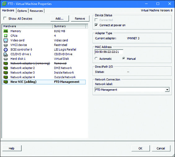
Step 2. Edit the virtual machine settings and open the Virtual Machine Properties window. Figure 5-36 shows all the hardware resources that are allocated to an FTD virtual appliance in the FTD – Virtual Machine Properties window.

Step 3. Click the Remove button and delete the network adapter that you want to upgrade from E1000 to VMXNET3.
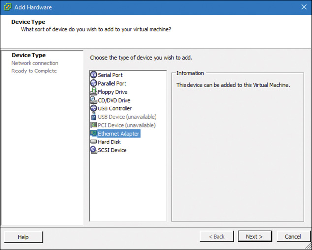
Step 4. Add a new VMXNET3 interface by clicking the Add button in the Virtual Machine Properties window. Then, in the Add Hardware window that appears (see Figure 5-37), select Ethernet Adapter from the device list.
Step 5. Select VMXNET3 from the Adapter Type drop-down. Figure 5-38 shows three types of network adapters: E1000, VMXNET2 (Enhanced), and VMXNET3. As of this writing, Firepower software does not support the VMXNET2 (Enhanced) adapter.

Step 6. Make sure the Network Label setting (that is, the association of a network with an adapter) is accurate and ensure that Connect at Power On is checked. Click Next when you are done.
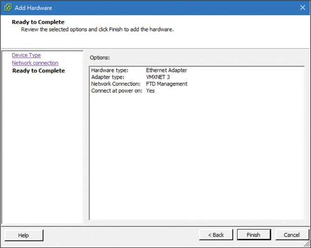
Step 7. In the Ready to Complete window, shown in Figure 5-39, check all the adapter settings and click Finish if everything looks good.
Step 8. If your virtual appliance has more than one network adapter (for example, an FTD virtual appliance must have at least four interfaces), repeat Steps 1–7 as many times as needed to upgrade all the other adapters to the same type.
Figure 5-40 shows the Virtual Machine Properties window after the management interface is replaced with a VMXNET3 adapter.
Step 9. Click OK in the Virtual Machine Properties window to save the changes and power on the virtual appliance.
Summary
This chapter describes various aspects of Firepower virtual appliances. You have learned how to deploy a virtual appliance, how to tune the resources for optimal performance, and how to investigate issues with a new deployment.
Quiz
1. Which file can be deployed directly into an ESXi host?
a. tar.gz
b. VMDK
c. OVF
d. MF
2. Which of the following network adapters provides the maximum throughput?
a. E1000
b. VMXNET2 (Enhanced)
c. VMXNET3
d. VMXNET-X
3. Which of the following options should not contribute to any connectivity issues between two Firepower virtual appliances?
a. The network adapter is configured as connected.
b. The Connected at Power On option is checked.
c. Promiscuous mode is enabled.
d. The network adapter types of two appliances are different.
4. Which of the following resources should not be adjusted on the FMC?
a. Network adapter
b. Storage
c. Memory
d. CPU
5. Which of the following statements is false?
a. An OVF file for VI completes the initial setup before deployment.
b. You cannot adjust the resource allocations on an FTD virtual appliance to improve its performance.
c. An FTD virtual appliance needs at least four interfaces.
d. A large deployment can be scaled by cloning an FTD virtual appliance by using VMware.