Chapter 6
EtherChannel
Objectives
Upon completion of this chapter, you will be able to answer the following questions:
What is EtherChannel technology?
How do you configure EtherChannel?
How do you troubleshoot EtherChannel?
Key Terms
This chapter uses the following key terms. You can find the definitions in the Glossary.
source MAC and destination MAC load balancing Page 177
source IP and destination IP load balancing Page 177
Port Aggregation Protocol (PAgP) Page 179
Introduction (6.0)
Your network design includes redundant switches and links. You have some version of STP configured to prevent Layer 2 loops. But now, like most network administrators, you realize that you could use more bandwidth and redundancy in your network. Not to worry, EtherChannel is here to help! EtherChannel aggregates links between devices into bundles. These bundles include redundant links. STP may block one of those links, but it will not block all of them. With EtherChannel your network can have redundancy, loop prevention, and increased bandwidth!
There are two protocols, PAgP and LACP. This module explains them both and shows you how to configure, verify, and troubleshoot them! A Syntax Checker and two Packet Tracer activities help you to better understand these protocols. What are you waiting for?
EtherChannel Operation (6.1)
Link aggregation is commonly implemented between access layer and distribution layer switches to increase the uplink bandwidth. In this section you will learn about the link aggregation operation in a switched LAN environment.
This topic describes link aggregation.
Link Aggregation (6.1.1)
There are scenarios in which more bandwidth or redundancy between devices is needed than what can be provided by a single link. Multiple links could be connected between devices to increase bandwidth. However, Spanning Tree Protocol (STP), which is enabled on Layer 2 devices like Cisco switches by default, will block redundant links to prevent switching loops, as shown in Figure 6-1.
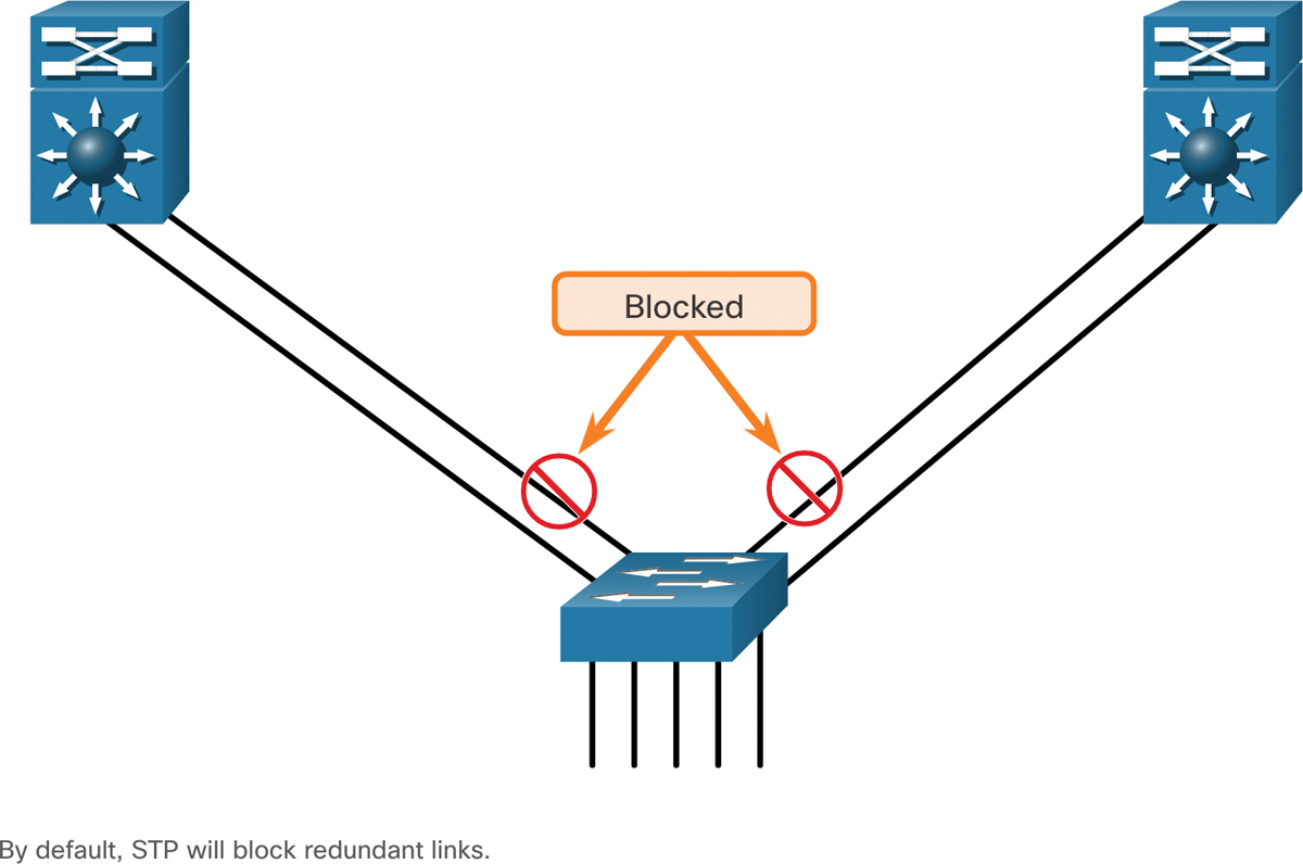
Figure 6-1 Blocked Ports in STP
A link aggregation technology is needed that allows redundant links between devices that will not be blocked by STP. That technology is known as EtherChannel.
EtherChannel is a link aggregation technology that groups multiple physical Ethernet links together into one single logical link. It is used to provide fault tolerance, load sharing, increased bandwidth, and redundancy between switches, routers, and servers.
EtherChannel technology makes it possible to combine the number of physical links between the switches to increase the overall speed of switch-to-switch communication.
EtherChannel (6.1.2)
EtherChannel technology was originally developed by Cisco as a LAN switch-to-switch technique of grouping several Fast Ethernet or Gigabit Ethernet ports into one logical channel. When an EtherChannel is configured, the resulting virtual interface is called a port channel. The physical interfaces are bundled together into a port channel interface, as shown in Figure 6-2.
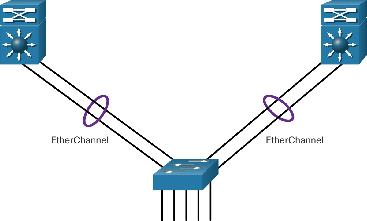
Figure 6-2 Bundling Links into an EtherChannel
Advantages of EtherChannel (6.1.3)
EtherChannel technology has many advantages, including the following:
Most configuration tasks can be done on the EtherChannel interface instead of on each individual port, ensuring configuration consistency throughout the links.
EtherChannel relies on existing switch ports. There is no need to upgrade the link to a faster and more expensive connection to have more bandwidth.
Load balancing takes place between links that are part of the same EtherChannel. Depending on the hardware platform, one or more load-balancing methods can be implemented. These methods include source MAC and destination MAC load balancing, or source IP and destination IP load balancing, across the physical links.
EtherChannel creates an aggregation that is seen as one logical link. When several EtherChannel bundles exist between two switches, STP may block one of the bundles to prevent switching loops. When STP blocks one of the redundant links, it blocks the entire EtherChannel. This blocks all the ports belonging to that EtherChannel link. Where there is only one EtherChannel link, all physical links in the EtherChannel are active because STP sees only one (logical) link.
EtherChannel provides redundancy because the overall link is seen as one logical connection. Additionally, the loss of one physical link within the channel does not create a change in the topology. Therefore, a spanning tree recalculation is not required. Assuming at least one physical link is present, the EtherChannel remains functional, even if its overall throughput decreases because of a lost link within the EtherChannel.
Implementation Restrictions (6.1.4)
EtherChannel has certain implementation restrictions, including the following:
Interface types cannot be mixed. For example, Fast Ethernet and Gigabit Ethernet cannot be mixed within a single EtherChannel.
Currently each EtherChannel can consist of up to eight compatibly-configured Ethernet ports. EtherChannel provides full-duplex bandwidth up to 800 Mbps (Fast EtherChannel) or 8 Gbps (Gigabit EtherChannel) between one switch and another switch or host.
The Cisco Catalyst 2960 Layer 2 switch currently supports up to six EtherChannels. However, as new IOSs are developed and platforms change, some cards and platforms may support increased numbers of ports within an EtherChannel link, as well as support an increased number of Gigabit EtherChannels.
The individual EtherChannel group member port configuration must be consistent on both devices. If the physical ports of one side are configured as trunks, the physical ports of the other side must also be configured as trunks within the same native VLAN. Additionally, all ports in each EtherChannel link must be configured as Layer 2 ports.
Each EtherChannel has a logical port channel interface, as shown in Figure 6-3. A configuration applied to the port channel interface affects all physical interfaces that are assigned to that interface.
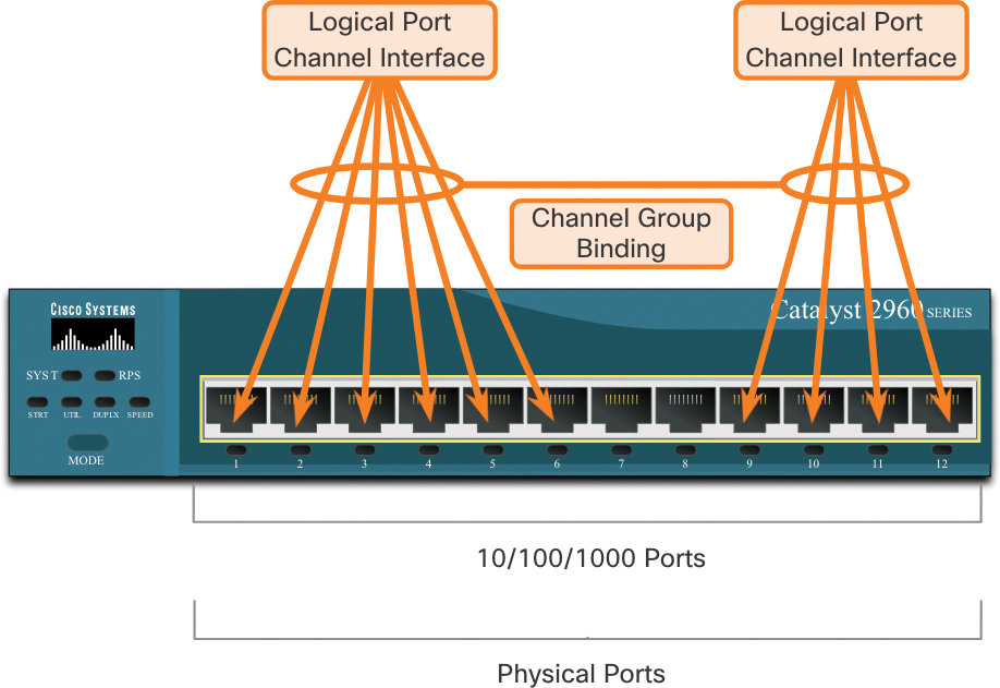
Figure 6-3 Physical and Logical Ports
AutoNegotiation Protocols (6.1.5)
EtherChannels can be formed through negotiation using one of two protocols, Port Aggregation Protocol (PAgP) or Link Aggregation Control Protocol (LACP). These protocols allow ports with similar characteristics to form a channel through dynamic negotiation with adjoining switches.
Note
It is also possible to configure a static or unconditional EtherChannel without PAgP or LACP.
PAgP Operation (6.1.6)
PAgP (pronounced “Pag - P”) is a Cisco-proprietary protocol that aids in the automatic creation of EtherChannel links. When an EtherChannel link is configured using PAgP, PAgP packets are sent between EtherChannel-capable ports to negotiate the forming of a channel. When PAgP identifies matched Ethernet links, it groups the links into an EtherChannel. The EtherChannel is then added to the spanning tree as a single port.
When enabled, PAgP also manages the EtherChannel. PAgP packets are sent every 30 seconds. PAgP checks for configuration consistency and manages link additions and failures between two switches. It ensures that when an EtherChannel is created, all ports have the same type of configuration.
Note
In EtherChannel, it is mandatory that all ports have the same speed, duplex setting, and VLAN information. Any port modification after the creation of the channel also changes all other channel ports.
PAgP helps create the EtherChannel link by detecting the configuration of each side and ensuring that links are compatible so that the EtherChannel link can be enabled when needed. The modes for PAgP are as follows:
On: This mode forces the interface to channel without PAgP. Interfaces configured in the on mode do not exchange PAgP packets.
PAgP desirable: This PAgP mode places an interface in an active negotiating state in which the interface initiates negotiations with other interfaces by sending PAgP packets.
PAgP auto: This PAgP mode places an interface in a passive negotiating state in which the interface responds to the PAgP packets that it receives but does not initiate PAgP negotiation.
The modes must be compatible on each side. If one side is configured to be in auto mode, it is placed in a passive state, waiting for the other side to initiate the EtherChannel negotiation. If the other side is also set to auto, the negotiation never starts, and the EtherChannel does not form. If all modes are disabled by using the no command, or if no mode is configured, the EtherChannel is disabled.
The on mode manually places the interface in an EtherChannel, without any negotiation. It works only if the other side is also set to on. If the other side is set to negotiate parameters through PAgP, no EtherChannel forms, because the side that is set to on mode does not negotiate.
No negotiation between the two switches means there is no checking to make sure that all the links in the EtherChannel are terminating on the other side, or that there is PAgP compatibility on the other switch.
PAgP Mode Settings Example (6.1.7)
Consider the two switches in Figure 6-4. Whether S1 and S2 establish an EtherChannel using PAgP depends on the mode settings on each side of the channel.
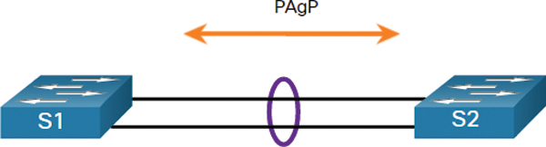
Figure 6-4 PAgP Topology
Table 6-1 shows the various combination of PAgP modes on S1 and S2 and the resulting channel establishment outcome.
Table 6-1 PAgP Modes
S1 |
S2 |
Channel Establishment |
On |
On |
Yes |
On |
Desirable/Auto |
No |
Desirable |
Desirable |
Yes |
Desirable |
Auto |
Yes |
Auto |
Desirable |
Yes |
Auto |
Auto |
No |
LACP Operation (6.1.8)
LACP is specified in IEEE 802.3ad and allows several physical ports to be bundled to form a single logical channel. LACP allows a switch to negotiate an automatic bundle by sending LACP packets to the other switch. It performs a function similar to PAgP with Cisco EtherChannel. Because LACP is an IEEE standard, it can be used to facilitate EtherChannels in multivendor environments. On Cisco devices, both protocols are supported.
Note
LACP was originally defined as IEEE 802.3ad. However, LACP is now defined in the newer IEEE 802.1AX standard for local and metropolitan area networks.
LACP provides the same negotiation benefits as PAgP. LACP helps create the EtherChannel link by detecting the configuration of each side and making sure that they are compatible so that the EtherChannel link can be enabled when needed. The modes for LACP are as follows:
On: This mode forces the interface to channel without LACP. Interfaces configured in the on mode do not exchange LACP packets.
LACP active: This LACP mode places a port in an active negotiating state. In this state, the port initiates negotiations with other ports by sending LACP packets.
LACP passive: This LACP mode places a port in a passive negotiating state. In this state, the port responds to the LACP packets that it receives but does not initiate LACP packet negotiation.
Just as with PAgP, modes must be compatible on both sides for the EtherChannel link to form. The on mode is repeated because it creates the EtherChannel configuration unconditionally, without PAgP or LACP dynamic negotiation.
LACP allows for eight active links, and also eight standby links. A standby link will become active should one of the current active links fail.
LACP Mode Settings Example (6.1.9)
Consider the two switches in Figure 6-5. Whether S1 and S2 establish an EtherChannel using LACP depends on the mode settings on each side of the channel.

Figure 6-5 LACP Topology
Table 6-2 shows the various combination of LACP modes on S1 and S2 and the resulting channel establishment outcome.
Table 6-2 LACP Modes
S1 |
S2 |
Channel Establishment |
On |
On |
Yes |
On |
Active/Passive |
No |
Active |
Active |
Yes |
Active |
Passive |
Yes |
Passive |
Active |
Yes |
Passive |
Passive |
No |
Check Your Understanding—EtherChannel Operation (6.1.10)
![]()
Refer to the online course to complete this activity.
Configure EtherChannel (6.2)
In this topic you learn how to configure link aggregation.
Configuration Guidelines (6.2.1)
Now that you know what EtherChannel is, this topic explains how to configure it. The following guidelines and restrictions are useful for configuring EtherChannel:
EtherChannel support: All Ethernet interfaces must support EtherChannel with no requirement that interfaces be physically contiguous.
Speed and duplex: Configure all interfaces in an EtherChannel to operate at the same speed and in the same duplex mode.
VLAN match: All interfaces in the EtherChannel bundle must be assigned to the same VLAN or be configured as a trunk (shown in the figure).
Range of VLANs: An EtherChannel supports the same allowed range of VLANs on all the interfaces in a trunking EtherChannel. If the allowed range of VLANs is not the same, the interfaces do not form an EtherChannel, even when they are set to auto or desirable mode.
Figure 6-6 shows a configuration that would allow an EtherChannel to form between S1 and S2.
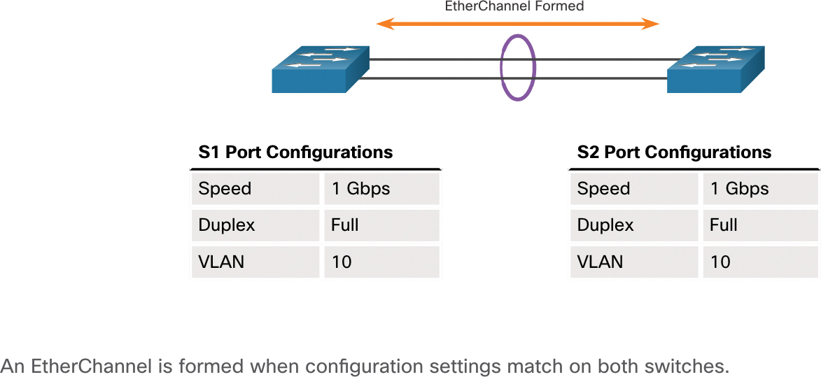
Figure 6-6 EtherChannel Forms When Configuration Matches
In Figure 6-7, S1 ports are configured as half-duplex. Therefore, an EtherChannel will not form between S1 and S2.
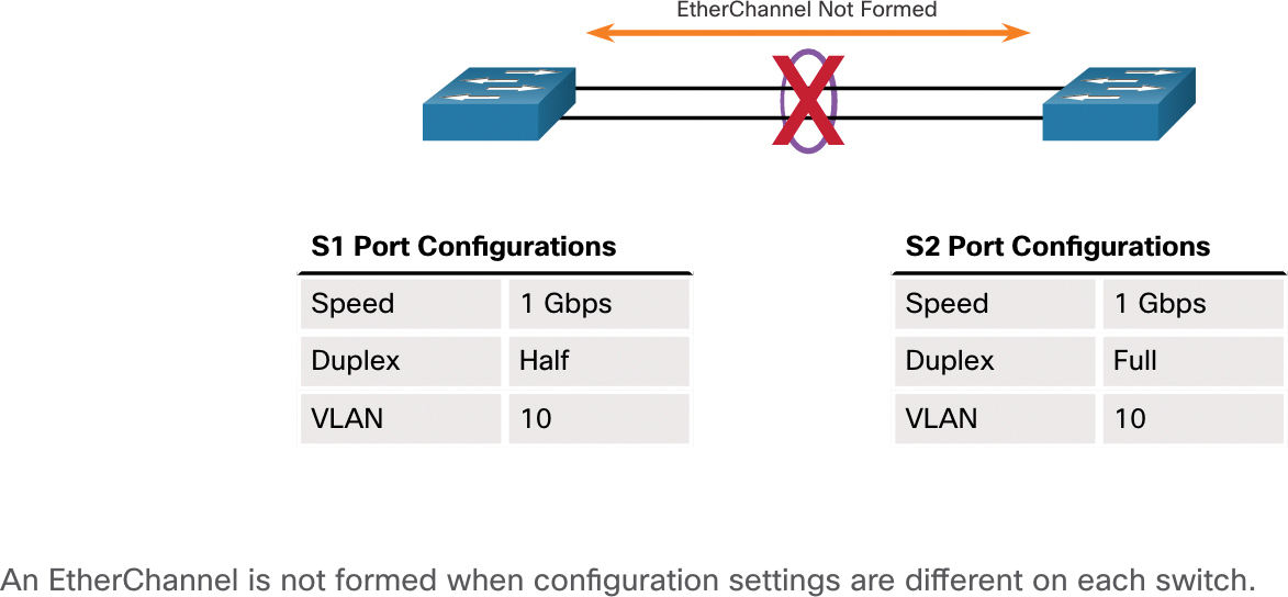
Figure 6-7 Example of EtherChannel Not Forming Because of a Configuration Mismatch
If these settings must be changed, configure them in port channel interface configuration mode. Any configuration that is applied to the port channel interface also affects individual interfaces. However, configurations that are applied to the individual interfaces do not affect the port channel interface. Therefore, making configuration changes to an interface that is part of an EtherChannel link may cause interface compatibility issues.
The port channel can be configured in access mode, trunk mode (most common), or on a routed port.
LACP Configuration Example (6.2.2)
EtherChannel is disabled by default and must be configured. The topology in Figure 6-8 will be used to demonstrate an EtherChannel configuration example using LACP.
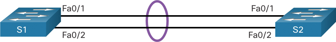
Figure 6-8 LACP Configuration Topology
Configuring EtherChannel with LACP requires the following three steps, as shown in Example 6-1:
![]()
Step 1. Specify the interfaces that compose the EtherChannel group using the interface range interface global configuration mode command. The range keyword allows you to select several interfaces and configure them all together.
Step 2. Create the port channel interface with the channel-group identifier mode active command in interface range configuration mode. The identifier specifies a channel group number. The mode active keywords identify this as an LACP EtherChannel configuration.
Step 3. To change Layer 2 settings on the port channel interface, enter port channel interface configuration mode using the interface port-channel command, followed by the interface identifier. In the example, S1 is configured with an LACP EtherChannel. The port channel 1 is configured as a trunk interface with the allowed VLANs specified.
Example 6-1 LACP Configuration Example
S1(config)# interface range FastEthernet 0/1 - 2
S1(config-if-range)# channel-group 1 mode active
Creating a port-channel interface Port-channel 1
S1(config-if-range)# exit
S1(config)#
S1(config-if)# interface port-channel 1
S1(config-if)# switchport mode trunk
S1(config-if)# switchport trunk allowed vlan 1,2,20
S1(config-if)#
Syntax Checker—Configure EtherChannel (6.2.3)
![]()
Configure the EtherChannel for S2 based on the specified requirements.
Packet Tracer—Configure EtherChannel (6.2.4)
![]()
Three switches have just been installed. There are redundant uplinks between the switches. As configured, only one of these links can be used; otherwise, a bridging loop might occur. However, using only one link utilizes only half of the available bandwidth. EtherChannel allows up to eight redundant links to be bundled together into one logical link. In this lab, you will configure Port Aggregation Protocol (PAgP), a Cisco EtherChannel protocol, and Link Aggregation Control Protocol (LACP), an IEEE 802.3ad open standard version of EtherChannel.
Verify and Troubleshoot EtherChannel (6.3)
In this topic you will learn how to troubleshoot a link aggregation implementation.
Verify EtherChannel (6.3.1)
As always, when you configure devices in your network, you must verify your configuration. If there are problems, you will also need to be able to troubleshoot and fix them. This topic gives you the commands to verify, as well as some common EtherChannel network problems and their solutions.
The verification command examples use the topology shown in Figure 6-9.

Figure 6-9 EtherChannel Topology
There are a number of commands to verify an EtherChannel configuration.
The show interfaces port-channel command displays the general status of the port channel interface. In Example 6-2, the Port Channel 1 interface is up.
Example 6-2 The show interfaces port-channel Command
S1# show interfaces port-channel 1
Port-channel1 is up, line protocol is up (connected)
  Hardware is EtherChannel, address is c07b.bcc4.a981 (bia c07b.bcc4.a981)
  MTU 1500 bytes, BW 200000 Kbit/sec, DLY 100 usec,
     reliability 255/255, txload 1/255, rxload 1/255
(output omitted)
When several port channel interfaces are configured on the same device, use the show etherchannel summary command to display one line of information per port channel. In Example 6-3, the switch has one EtherChannel configured; group 1 uses LACP.
The interface bundle consists of the FastEthernet0/1 and FastEthernet0/2 interfaces. The group is a Layer 2 EtherChannel, and it is in use, as indicated by the letters SU next to the port channel number.
Example 6-3 The show etherchannel summary Command
S1# show etherchannel summary
Flags:   D - down        P - bundled in port-channel
         I - stand-alone s - suspended
         H - Hot-standby (LACP only)
         R - Layer3      S - Layer2
         U - in use      N - not in use, no aggregation
         f - failed to allocate aggregator
         M - not in use, minimum links not met
         m - not in use, port not aggregated due to minimum links not met
         u - unsuitable for bundling
         w - waiting to be aggregated
         d - default port
         A - formed by Auto LAG
Number of channel-groups in use: 1
Number of aggregators:           1
Group  Port-channel  Protocol    Ports
------+-------------+-----------+-----------------------------------------------
1      Po1(SU)         LACP      Fa0/1(P)    Fa0/2(P)
Use the show etherchannel port-channel command to display information about a specific port channel interface. As shown in Example 6-4, the Port Channel 1 interface consists of two physical interfaces, FastEthernet0/1 and FastEthernet0/2. It uses LACP in active mode. It is properly connected to another switch with a compatible configuration, which is why the port channel is said to be in use.
Example 6-4 The show etherchannel port-channel Command
S1# show etherchannel port-channel
                 Channel-group listing:
                 ----------------------
Group: 1
----------
                 Port-channels in the group:
                 ---------------------------
Port-channel: Po1    (Primary Aggregator)
------------
Age of the Port-channel   = 0d:01h:02m:10s
Logical slot/port   = 2/1           Number of ports = 2
HotStandBy port = null
Port state          = Port-channel Ag-Inuse
Protocol            =   LACP
Port security       = Disabled
Load share deferral = Disabled
Ports in the Port-channel:
Index   Load   Port     EC state          No of bits
------+------+------+------------------+-----------
  0     00     Fa0/1    Active              0
  0     00     Fa0/2    Active              0
Time since last port bundled:   0d:00h:09m:30s    Fa0/2
On any physical interface member of an EtherChannel bundle, the show interfaces interface etherchannel command can provide information about the role of the interface in the EtherChannel, as shown in Example 6-5. The interface FastEthernet0/1 is part of the EtherChannel bundle 1. The protocol for this EtherChannel is LACP.
Example 6-5 The show interfaces etherchannel Command
S1# show interfaces f0/1 etherchannel
Port state     = Up Mstr Assoc In-Bndl
Channel group  = 1            Mode = Active          Gcchange = -
Port-channel   = Po1          GC   =   -             Pseudo port-channel = Po1
Port index     = 0            Load = 0x00            Protocol =   LACP
Flags:  S - Device is sending Slow LACPDUs   F - Device is sending fast LACPDUs.
        A - Device is in active mode.        P - Device is in passive mode.
Local information:
                              LACP port      Admin     Oper    Port
Port      Flags    State      Priority       Key       Number  State
Fa0/1     SA       bndl       32768          0x1       0x1     0x102       0x3D
Partner's information:
                   LACP port                         Admin  Oper  Port    Port
Port      Flags    Priority   Dev ID         Age     key    Key   Number  State
Fa0/1     SA       32768      c025.5cd7.ef00 12s     0x0    0x1   0x102   0x3Dof
  the port in the current state: 0d:00h:11m:51sllowed vlan 1,2,20
Common Issues with EtherChannel Configurations (6.3.2)
All interfaces within an EtherChannel must have the same configuration of speed and duplex mode, native and allowed VLANs on trunks, and access VLAN on access ports. Ensuring these configurations will significantly reduce network problems related to EtherChannel. Common EtherChannel issues include the following:
Assigned ports in the EtherChannel are not part of the same VLAN, or not configured as trunks. Ports with different native VLANs cannot form an EtherChannel.
Trunking was configured on some of the ports that make up the EtherChannel, but not all of them. It is not recommended that you configure trunking mode on individual ports that make up the EtherChannel. When configuring a trunk on an EtherChannel, verify the trunking mode on the EtherChannel.
If the allowed range of VLANs is not the same, the ports do not form an EtherChannel even when PAgP is set to the auto or desirable mode.
The dynamic negotiation options for PAgP and LACP are not compatibly configured on both ends of the EtherChannel.
Note
It is easy to confuse PAgP or LACP with DTP, because they are all protocols used to automate behavior on trunk links. PAgP and LACP are used for link aggregation (EtherChannel). DTP is used for automating the creation of trunk links. When an EtherChannel trunk is configured, typically EtherChannel (PAgP or LACP) is configured first and then DTP.
Troubleshoot EtherChannel Example (6.3.3)
In Figure 6-10, interfaces F0/1 and F0/2 on switches S1 and S2 are connected with an EtherChannel. However, the EtherChannel is not operational.
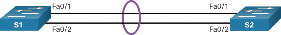
Figure 6-10 EtherChannel Topology
Use the following steps to troubleshoot the EtherChannel.
![]()
Step 1. View the EtherChannel Summary Information
The output of the show etherchannel summary command in Example 6-6 indicates that the EtherChannel is down.
Example 6-6 Checking the EtherChannel Status
S1# show etherchannel summary
Flags:   D - down         P - bundled in port-channel
         I - stand-alone  s - suspended
         H - Hot-standby (LACP only)
         R - Layer3       S - Layer2
         U - in use       N - not in use, no aggregation
         f - failed to allocate aggregator
         M - not in use, minimum links not met
         m - not in use, port not aggregated due to minimum links not met
         u - unsuitable for bundling
         w - waiting to be aggregated
         d - default port
         A - formed by Auto LAG
Number of channel-groups in use: 1
Number of aggregators:           1
Group  Port-channel  Protocol    Ports
------+-------------+-----------+-----------------------------------------------
1      Po1(SD)         -        Fa0/1(D)    Fa0/2(D)
Step 2. View Port Channel Configuration
In the show run | begin interface port-channel output in Example 6-7, more detailed output indicates that there are incompatible PAgP modes configured on S1 and S2.
Example 6-7 Piping show run to Check the EtherChannel Configuration
S1# show run | begin interface port-channel
interface Port-channel1
 switchport trunk allowed vlan 1,2,20
 switchport mode trunk
!
interface FastEthernet0/1
 switchport trunk allowed vlan 1,2,20
 switchport mode trunk
 channel-group 1 mode on
!
interface FastEthernet0/2
 switchport trunk allowed vlan 1,2,20
 switchport mode trunk
 channel-group 1 mode on
!======================================
S2# show run | begin interface port-channel
interface Port-channel1
 switchport trunk allowed vlan 1,2,20
 switchport mode trunk
!
interface FastEthernet0/1
 switchport trunk allowed vlan 1,2,20
 switchport mode trunk
 channel-group 1 mode desirable
!
interface FastEthernet0/2
 switchport trunk allowed vlan 1,2,20
 switchport mode trunk
 channel-group 1 mode desirable
Step 3. Correct the Misconfiguration
To correct the issue, the PAgP mode on the EtherChannel is changed to desirable, as shown in Example 6-8.
Example 6-8 Correcting the PAgP Mode
S1(config)# no interface port-channel 1
S1(config)# interface range fa0/1 - 2
S1(config-if-range)# channel-group 1 mode desirable
Creating a port-channel interface Port-channel 1
S1(config-if-range)# no shutdown
S1(config-if-range)# exit
S1(config)# interface range fa0/1 - 2
S1(config-if-range)# channel-group 1 mode desirable
S1(config-if-range)# no shutdown
S1(config-if-range)# interface port-channel 1
S1(config-if)# switchport mode trunk
S1(config-if)# end
S1#
Note
EtherChannel and STP must interoperate. For this reason, the order in which EtherChannel-related commands are entered is important, which is why you see interface Port-Channel 1 removed and then re-added with the channel-group command, in contrast to directly changed. If one tries to change the configuration directly, STP errors cause the associated ports to go into blocking or errdisabled state.
Step 4. Verify EtherChannel Is Operational
The EtherChannel is now active, as verified by the output of the show etherchannel summary command in Example 6-9.
Example 6-9 Verifying the EtherChannel Is Now Operational
S1# show etherchannel summary
Flags:   D - down        P - bundled in port-channel
         I - stand-alone s - suspended
         H - Hot-standby (LACP only)
         R - Layer3      S - Layer2
         U - in use      N - not in use, no aggregation
         f - failed to allocate aggregator
         M - not in use, minimum links not met
         m - not in use, port not aggregated due to minimum links not met
         u - unsuitable for bundling
         w - waiting to be aggregated
         d - default port
         A - formed by Auto LAG
Number of channel-groups in use: 1
Number of aggregators:            1
Group  Port-channel  Protocol    Ports
------+-------------+-----------+-----------------------------------------------
1      Po1(SU)         PAgP      Fa0/1(P)    Fa0/2(P)
Packet Tracer—Troubleshoot EtherChannel (6.3.4)
![]()
Four switches were recently configured by a junior technician. Users are complaining that the network is running slowly and would like you to investigate.
Summary (6.4)
The following is a summary of each topic in the module:
EtherChannel Operation
To increase bandwidth or redundancy, multiple links could be connected between devices. However, STP will block redundant links to prevent switching loops. EtherChannel is a link aggregation technology that allows redundant links between devices that will not be blocked by STP. EtherChannel groups multiple physical Ethernet links together into one single logical link. It provides fault tolerance, load sharing, increased bandwidth, and redundancy between switches, routers, and servers. When an EtherChannel is configured, the resulting virtual interface is called a port channel. EtherChannel has several advantages, as well as some restrictions to implementation. EtherChannels can be formed through negotiation using one of two protocols, PAgP or LACP. These protocols allow ports with similar characteristics to form a channel through dynamic negotiation with adjoining switches. When an EtherChannel link is configured using Cisco-proprietary PAgP, PAgP packets are sent between EtherChannel-capable ports to negotiate the forming of a channel. Modes for PAgP are On, PAgP desirable, and PAgP auto. LACP performs a function similar to PAgP with Cisco EtherChannel. Because LACP is an IEEE standard, it can be used to facilitate EtherChannels in multivendor environments. Modes for LACP are On, LACP active, and LACP passive.
Configure EtherChannel
The following guidelines and restrictions are useful for configuring EtherChannel:
EtherChannel support: All Ethernet interfaces on all modules must support EtherChannel with no requirement that interfaces be physically contiguous, or on the same module.
Speed and duplex: Configure all interfaces in an EtherChannel to operate at the same speed and in the same duplex mode.
VLAN match: All interfaces in the EtherChannel bundle must be assigned to the same VLAN or be configured as a trunk.
Range of VLANs: An EtherChannel supports the same allowed range of VLANs on all the interfaces in a trunking EtherChannel.
Configuring EtherChannel with LACP requires three steps:
Step 1. Specify the interfaces that compose the EtherChannel group using the interface range interface global configuration mode command.
Step 2. Create the port channel interface with the channel-group identifier mode active command in interface range configuration mode.
Step 3. To change Layer 2 settings on the port channel interface, enter port channel interface configuration mode using the interface port-channel command, followed by the interface identifier.
Verify and Troubleshoot EtherChannel
There are a number of commands to verify an EtherChannel configuration, including show interfaces port-channel, show etherchannel summary, show etherchannel port-channel, and show interfaces etherchannel. Common EtherChannel issues include the following:
Assigned ports in the EtherChannel are not part of the same VLAN, or not configured as trunks. Ports with different native VLANs cannot form an EtherChannel.
Trunking was configured on some of the ports that make up the EtherChannel, but not all of them.
If the allowed range of VLANs is not the same, the ports do not form an EtherChannel even when PAgP is set to the auto or desirable mode.
The dynamic negotiation options for PAgP and LACP are not compatibly configured on both ends of the EtherChannel.
Packet Tracer—Implement EtherChannel (6.4.1)
![]()
You have been tasked with designing an EtherChannel implementation for a company that wants to improve the performance of the switch trunk links. You will try several ways of implementing the EtherChannel links to evaluate which is the best for the company. You will build the topology, configure trunk ports, and implement LACP and PAgP EtherChannels.
Lab—Implement EtherChannel (6.4.2)
![]()
In this lab, you complete the following objectives:
Part 1: Build the Network and Configure Basic Device Settings
Part 2: Create VLANs and Assign Switch Ports
Part 3: Configure 802.1Q Trunks Between the Switches
Part 4: Implement and Verify an EtherChannel Between the Switches
Practice
The following activities provide practice with the topics introduced in this chapter. The Labs are available in the companion Switching, Routing, and Wireless Essentials Labs and Study Guide (CCNAv7) (ISBN 9780136634386). The Packet Tracer Activity instructions are also in the Labs & Study Guide. The PKA files are found in the online course.
Lab
![]()
Lab 6.4.2: Implement EtherChannel
Packet Tracer Activities
![]()
Packet Tracer 6.2.4: Configure EtherChannel
Packet Tracer 6.3.4: Troubleshoot EtherChannel
Packet Tracer 6.4.1: Implement EtherChannel
Check Your Understanding Questions
Complete all the review questions listed here to test your understanding of the topics and concepts in this chapter. The appendix “Answers to the ‘Check Your Understanding’ Questions” lists the answers.
1. There has been an increase in network traffic between two Catalyst 2960 switches, and their FastEthernet trunk link has reached its capacity. How can traffic flow be improved?
Add routers between the switches to create additional broadcast domains.
Bundle physical ports using EtherChannel.
Configure smaller VLANs to decrease the size of the collision domain.
Increase the speed of the ports using the bandwidth command.
2. Which two load-balancing methods can be implemented with EtherChannel technology? (Choose two.)
Destination IP to destination MAC
Destination IP to source IP
Destination MAC to destination IP
Destination MAC to source MAC
Source IP and destination IP
Source MAC and destination MAC
3. Which statement is true regarding the use of PAgP to create EtherChannels?
It increases the number of ports that are participating in spanning tree.
It is Cisco proprietary.
It mandates that an even number of ports (2, 4, 6, etc.) be used for aggregation.
It requires full duplex.
It requires more physical links than LACP does.
4. Which two protocols are link aggregation protocols? (Choose two.)
802.3ad
EtherChannel
PAgP
RSTP
STP
5. Which combination of channel-group modes will establish an EtherChannel?
Switch 1 set to auto; switch 2 set to auto.
Switch 1 set to auto; switch 2 set to on.
Switch 1 set to desirable; switch 2 set to desirable.
Switch 1 set to on; switch 2 set to desirable.
6. Which interface configuration command will enable the port to initiate an LACP EtherChannel?
channel-group mode active
channel-group mode auto
channel-group mode desirable
channel-group mode on
channel-group mode passive
7. Which interface configuration command will enable the port to establish an EtherChannel only if it receives PAgP packets from the other switch?
channel-group mode active
channel-group mode auto
channel-group mode desirable
channel-group mode on
channel-group mode passive
8. Which statement describes a characteristic of EtherChannel?
It can combine up to a maximum of 4 physical links.
It can bundle mixed types of 100 Mbps and 1 Gbps Ethernet links.
It consists of multiple parallel links between a switch and a router.
It is made by combining multiple physical links that are seen as one link between two switches.
9. What are two advantages of using LACP? (Choose two.)
LACP allows automatic formation of EtherChannel links.
LACP allows use of multivendor devices.
LACP decreases the amount of configuration that is needed on a switch for EtherChannel.
LACP eliminates the need for the Spanning Tree Protocol.
LACP increases redundancy to Layer 3 devices.
LACP provides a simulated environment for testing link aggregation.
10. Which three settings must match in order for switch ports to form an EtherChannel? (Choose three.)
Non-trunk ports must belong to the same VLAN.
Port security violation settings on interconnecting ports must match.
The duplex settings on interconnecting ports must match.
The port channel group number on interconnecting switches must match.
The SNMP community strings must match.
The speed settings on interconnecting ports must match.