Chapter 4
Pattern Language Introduction
In Part 1, we learned that remote APIs have become an important feature of modern distributed software systems. APIs provide integration interfaces exposing remote system functionality to end-user applications such as mobile clients, Web applications, and third-party systems. Not only end-user applications consume and rely on APIs—distributed backend systems and microservices within those systems require APIs to be able to work with each other as well.
Lakeside Mutual, a fictitious insurance company, and its microservices-based applications provided us with an example case. We saw that API design and evolution involve many recurring design issues to resolve conflicting requirements and find appropriate trade-offs. Decision models for groups of related issues presented options and criteria to guide us through the required design work. Patterns appeared as alternative options in these decisions.
This chapter takes the next step. It starts with a pattern language overview and then proposes navigation paths through the language. It also introduces a first set of basic scoping and structuring patterns. Having read this chapter, you will be able to explain the scope of our pattern language (in terms of topics covered and architectural concerns) and find patterns you are interested in (for instance, by project phase). You will also be able to characterize the API under construction by its visibility and integration type by way of foundation patterns and know about the basic structure patterns that constitute the syntactic building blocks of request and response messages (and many of the other patterns in our language).
Positioning and Scope
According to our domain model, established in Chapter 1, “Application Programming Interface (API) Fundamentals,” API clients and providers exchange request and response messages to call operations in API endpoints. Many of our patterns focus on the payload content of such messages that contain one or more representation elements, possibly nested. Enterprise Integration Patterns [Hohpe 2003] offers three alternative patterns about this message content: “Document Message,” “Command Message,” and “Event Message.” In messaging systems, such messages travel from the sending endpoint to the receiving endpoint over communication “Channels.” These Channels may be offered by queue-based messaging systems but also come as HTTP connections or other use integration technologies, such as GraphQL and gRPC. Protocol capabilities and configuration, as well as message size and content structure, influence the quality properties of an API and its implementation. In this messaging context, APIs can be seen as “Service Activators” [Hohpe 2003]—viewed from the communication channels, they serve as “Adapters” [Gamma 1995] for the application services available in the API implementation.
In our pattern language, we look into the command, document, and event messages in terms of their inner structures. We also investigate the roles played by representation elements, operations, and API endpoints—irrespective of the communication protocols used. We discuss how to group messages into endpoints to achieve suitable API granularity and coupling, how to document APIs, and how to manage the evolution of API endpoints and their parts.
We are particularly interested in message payloads that are exchanged as JSON objects—for instance, via HTTP GET, POST, and PUT—and in message queues offered by cloud providers or messaging systems (such as ActiveMQ or RabbitMQ). JSON is a popular message exchange format in Web APIs; our patterns work equally well when XML documents or other text structures are exchanged. They can even be applied to define the content of messages with binary encodings.
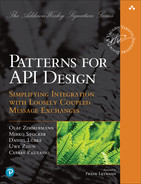
Figure 4.1 visualizes the scope of our patterns in a Web API example. An HTTP GET, shown as a curl command, asks for information about a single customer, rgpp0wkpec, of Lakeside Mutual (the case introduced in Chapter 2, “Lakeside Mutual Case Study”).
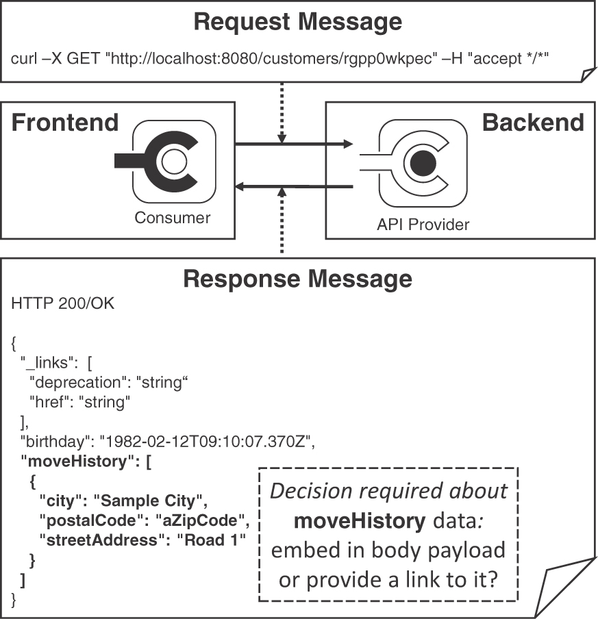
Figure 4.1 Exemplary API call: Exchanged messages and their structure
The exemplary response message is nested: the customer information contains not only the birthday but also a log of address changes in the form of a moveHistory. Indicated by the JSON array notation [...], a collection of relocation moves could be returned (in the example, the array contains only one move destination). Each move destination is characterized by three strings, "city", "postal-Code", "street-Address", wrapped in the JSON object notation {...} in the figure. This two-level structure raises an important, recurring API design issue:
Should complex data whose parts have containment or other domain-level relations be embedded in message representations, or should links be provided to look up this data with separate calls to other operations in the same (or other) API endpoints?
Two of our patterns offer alternative answers to this question: EMBEDDED ENTITY (shown in Figure 4.1) and LINKED INFORMATION HOLDER. EMBEDDED ENTITY injects nested data representations into the payload, whereas a LINKED INFORMATION HOLDER places hyperlinks in the payload. In the latter case, the client has to follow these hyperlinks to obtain the referenced data in subsequent requests to the endpoint location found in the links. The chosen combination of these two patterns has a strong impact on the API quality. For instance, message size and number of interactions influence both performance and changeability. Both patterns are valid choices, depending on network and endpoint capabilities, information needs and data access profiles of clients, backend location of the source data, and so on. These criteria, therefore, are pattern selection and adoption forces. We will come back to these patterns and their forces in Chapter 7, “Refine Message Design for Quality.”
Patterns: Why and How?
Patterns can help resolve API design issues, presenting proven solutions to problems recurring in a particular context (here, API design and evolution). Patterns are platform-independent by definition, thus avoiding concept, technology, and vendor lock-in. They form a common language for a domain. Adequate pattern usage can make the designs that adopt them easier to understand, port, and evolve.
Each pattern text can be seen as a small, specialized, standalone article. These texts are structured according to a common template:
When and Why to Apply establishes the context and preconditions for pattern eligibility, followed by a problem statement that specifies a design issue to be resolved. Different forces on the design explain why the problem is hard to solve. Architectural decision drivers and conflicting quality attributes are often referenced here; a nonsolution may also be pointed out.
The How It Works section presents a conceptual, generalized solution to the design question from the problem statement that describes how the solution works and which variants (if any) we observed in practice.
The Example section shows how the solution can be implemented in a concrete application context, for instance, when working with a particular technology set such as HTTP and JSON.
The Discussion section explains to what extent the solution resolves the pattern forces; it may also include additional pros and cons and identify alternative solutions.
The Related Patterns section points to the next patterns that become eligible and interesting once a particular one has been applied.
Finally, additional pointers and references are given under More Information.
Coming back to our two exemplary patterns, LINKED INFORMATION HOLDER and EMBEDDED ENTITY are documented in this format in Chapter 7.
Note that using a pattern does not dictate a particular implementation but leaves a lot of flexibility for its project-context-specific adoption. In fact, patterns should never be followed blindly but should be seen as a tool or guide. A product- or project-specific design can satisfy its concrete, actual requirements only if it knows them (which is hard for a generalized artifact such as a pattern).
Navigating through the Patterns
When we decided how to organize our patterns, we looked at two other books for inspiration: Enterprise Integration Patterns [Hohpe 2003] is organized by the life cycle of messages traveling through a distributed system, from creation and sending to routing, transforming, and receiving. Patterns of Enterprise Application Architecture [Fowler 2002] uses logical layers as a chapter and topic breakdown, progressing from domain layer to persistence layer and presentation layer.
Regrettably, neither layers nor life cycles alone seemed to work well for the API domain. Hence, we could not decide on one best way to organize but offer multiple ones to guide you through the patterns: architectural scope (as defined by the API domain model from Chapter 1), topic categories, and refinement phases.1
1. This “ask for one, get three” tactic is an exception to our general rule, “if in doubt, leave it out” [Zimmermann 2021b], fortunately only on the meta-level. Hopefully, standards committees and API designers stick to this rule better than we do ;-).
Structural Organization: Find Patterns by Scope
Most of our patterns focus on API building blocks at different levels of abstraction and detail; some concern the API as a whole and its documentation, both technical and commercial. The resulting architectural scopes are API as a whole, endpoint, operation, and message. We introduced these basic concepts in the API domain model in Chapter 1. Figure 4.2 calls out patterns for these five scopes.
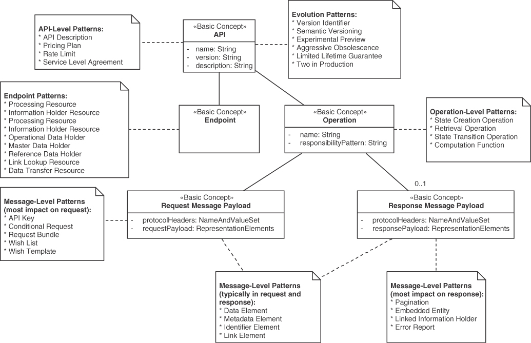
Figure 4.2 Patterns by domain model element and architectural scope
Patterns such as API DESCRIPTION and SERVICE LEVEL AGREEMENT concern the API as a whole. Others, such as PROCESSING RESOURCE and DATA TRANSFER RESOURCE, operate on single endpoints. Many patterns deal with operation or message design; some of these primarily target request messages (API KEY, WISH LIST), and others are more focused on response messages (PAGINATION, ERROR REPORT). Element stereotypes may appear both in requests and responses (IDENTIFIER ELEMENT, METADATA ELEMENT).
Call to action: When being confronted with an API design task, ask yourself which of these scopes you are about to deal with and refer to Figure 4.2 to find patterns of interest for this task.
Theme Categorization: Search for Topics
We grouped the patterns into five categories. Each category answers several related topical questions:
Foundation patterns: Which types of systems and components are integrated? From where should an API be accessible? How should it be documented?
Responsibility patterns: What is the architectural role played by each API end-point? What are the operation responsibilities? How do these roles and responsibilities impact service decomposition and API granularity?
Structure patterns: What is an adequate number of representation elements for request and response messages? How should these elements be structured? How can they be grouped and annotated?
Quality patterns: How can an API provider achieve a certain level of design time and runtime qualities while using its resources in a cost-effective way? How can the API quality trade-offs be communicated and accounted for?
Evolution patterns: How can life-cycle management concerns such as support periods and versioning be dealt with? How can backward compatibility be promoted and unavoidable breaking changes be communicated?
These theme categories organize the decision models in Chapter 3, “API Decision Narratives,” and the Web site supporting this book.2 Figure 4.3 groups the patterns by book chapter. The theme categories and Chapters 4 to 8 correspond with each other but for only two exceptions: API DESCRIPTION from the foundation category and three patterns related to quality management (RATE LIMIT, PRICING PLAN, SERVICE LEVEL AGREEMENT) are factored out into a separate Chapter 9, “Document and Communicate API Contracts.” The patterns API KEY, ERROR REPORT, and CONTEXT REPRESENTATION are related to quality but appear in Chapter 6, “Design Request and Response Message Representations,” due to their role of special-purpose representations. The cheat sheet in Appendix A follows the same structure.
Figure 4.3 Patterns by chapter
Call to action: Think about an API design issue you were confronted with recently. Does it fit in any of the preceding categories? Do any of the questions and pattern names suggest that the pattern might be able to resolve the issue? If so, you may want to go to the respective chapter and pattern right now (and return here later). If you need more information, you can consult the cheat sheet in Appendix A.
Time Dimension: Follow Design Refinement Phases
Roughly following the “Unified Process” [Kruchten 2000], an API design evolves from project/product inception to design elaboration, implementation construction iterations, and project/product transition. Table 4.1 categorizes patterns by process phases; note that some patterns can be applied in multiple phases.
Table 4.1 Patterns by Phase
Phase | Category | Patterns |
|---|---|---|
Inception | Foundation | PUBLIC API, COMMUNITY API, SOLUTION-INTERNAL API |
BACKEND INTEGRATION, FRONTEND INTEGRATION | ||
API DESCRIPTION | ||
Elaboration | Responsibility | INFORMATION HOLDER RESOURCE, PROCESSING RESOURCE |
MASTER DATA HOLDER, OPERATIONAL DATA HOLDER, REFERENCE DATA HOLDER | ||
DATA TRANSFER RESOURCE, LINK LOOKUP RESOURCE | ||
Quality | API KEY, CONTEXT REPRESENTATION, ERROR REPORT | |
Construction | Structure | ATOMIC PARAMETER, ATOMIC PARAMETER LIST, PARAMETER TREE, PARAMETER FOREST |
DATA ELEMENT, ID ELEMENT, LINK ELEMENT, METADATA ELEMENT | ||
Responsibility | STATE CREATION OPERATION, STATE TRANSITION OPERATION | |
RETRIEVAL OPERATION, COMPUTATION FUNCTION | ||
Quality | PAGINATION | |
WISH LIST, WISH TEMPLATE | ||
EMBEDDED ENTITY, LINKED INFORMATION HOLDER | ||
CONDITIONAL REQUEST, REQUEST BUNDLE | ||
Transition | Foundation | API DESCRIPTION |
Quality | SERVICE LEVEL AGREEMENT, PRICING PLAN, RATE LIMIT | |
Evolution | SEMANTIC VERSIONING, VERSION IDENTIFIER | |
AGGRESSIVE OBSOLESCENCE, EXPERIMENTAL PREVIEW | ||
LIMITED LIFETIME GUARANTEE, TWO IN PRODUCTION |
APIs endpoints are identified and characterized by their roles in the overall system/architecture at the early stages (inception). Next, operations are drafted with their request and response message structure conceptualized and designed initially (elaboration). Quality improvements follow (construction). An approach to versioning and a support/lifetime strategy is specified for APIs when they go live (transition); updates are possible later on.
While Table 4.1 has an order from top to bottom (as all tables do), it can be walked through multiple times, even within a single two-week sprint. We do not propose a waterfall model here; it is perfectly fine to go back and forth, for instance when applying agile project organization practices. In other words, each sprint may contain inception, elaboration, construction, and transition tasks (and apply related patterns).
You might be wondering how the Align-Define-Design-Refine (ADDR) phases (see introduction to Part 2) relate to the phases in the Unified Process and Table 4.1. Our take is: Align corresponds to inception, the Define activities happen during elaboration. Design work stretches from elaboration to construction iterations; construction and transition (and later evolution and maintenance phases) provide opportunities to Refine the design continuously.
Call to action: Which phase is your current API design effort in? Do the listed patterns suggest being eligible for consideration in your design? You may want to revisit Table 4.1 each time your design reaches a certain milestone or each time you pick an API-related story from the product backlog at the start of a sprint.
How to Navigate: The Map to MAP
You can use the three navigation aids structure from this section—structure/scope, theme category/chapter, and time/phase—to explore the language for your immediate needs if you are not yet ready to read Part 2 page by page. Having picked one or more entry points, you can then follow the “Related Patterns” pointers provided in each pattern to move on; you can also return to one of the three organizers (scope, topic, phase). Having studied a few patterns, you may want to check out the Lakeside Mutual case study or the real-world pattern stories in Chapter 10, “Real-World Pattern Stories,” to return to the big picture and learn how individual patterns can be combined.
The following section introduces basic API foundation and message structure patterns eligible during the Align phase of ADDR, with Chapters 5 to 9 covering the remaining phases Define, Design, and Refine as well as additional topics.
Foundations: API Visibility and Integration Types
The patterns presented in this section are rather simplistic terms of design forces and their resolution, but they serve as building blocks for the subsequent, more advanced patterns. Therefore, we present them here in a simplified form: Context and Problem, Solution, and Details. Feel free to proceed to Chapter 5, “Define Endpoint Types and Operations,” and return here as needed.
The foundation patterns deal with the two strategic decisions:
Which types of systems, subsystems, and components are integrated?
From where should an API be accessible?
Answering these two questions helps to scope and characterize an API and its purpose: FRONTEND INTEGRATION and BACKEND INTEGRATION are two types of directions (or purpose and architectural position) of APIs. PUBLIC API, COMMUNITY API, and SOLUTION-INTERNAL API define API visibility. Figure 4.4 provides a pattern map for these five patterns.
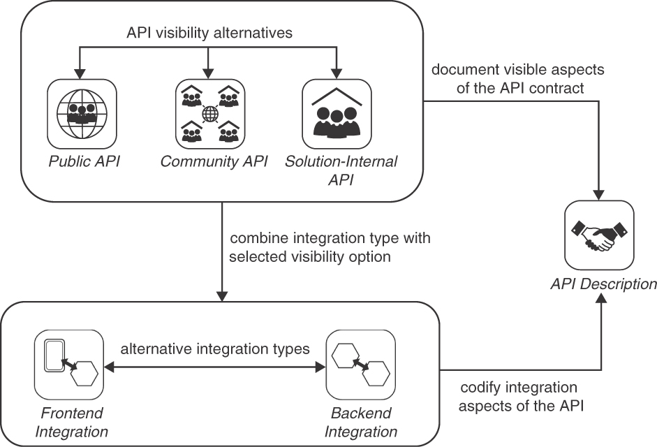
Figure 4.4 Pattern map for foundation patterns
Note that the API DESCRIPTION pattern is covered in Chapter 9.
 Pattern: FRONTEND INTEGRATION
In Chapter 1, we motivated the emergence of mobile apps and cloud-native applications as one reason why APIs matter so much. They provide mobile apps and Web clients of cloud applications with data and access to provider-side processing capabilities.
How can client-side end-user interfaces that are physically separated from server-side business logic and data storage be populated and updated with computing results, result sets from searches in data sources, and detailed information about data entities? How can application frontends invoke activities in a backend or upload data to it?
Let the backend of a distributed application expose its services to one or more application frontends via a message-based remote FRONTEND INTEGRATION API.
The application frontends serving end users may be internal ones or be part of external systems. FRONTEND INTEGRATION APIs are consumed by API clients in these types of application frontends. Figure 4.5 positions the FRONTEND INTEGRATION pattern in its context.
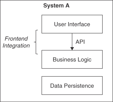
Figure 4.5 FRONTEND INTEGRATION: An API connects a remote user interface with backend logic and data
The Business Logic Layer [Fowler 2002] in the backend is a natural entry point. Sometimes the user interface is also split up between client and server. In such cases, the API might reside on the user interface level as well.
Details
Decide whether the API is a PUBLIC API, a COMMUNITY API, or a SOLUTION-INTERNAL API. Compose the request and, optionally, response messages of the API operations from one or more ATOMIC PARAMETERS and PARAMETER TREES (see later sections for explanations of these patterns).
Realize the selected API endpoint candidates with the help of the role and responsibility patterns (Chapter 5), the message structure patterns (Chapter 6), and the quality patterns (Chapters 6 and 7). Consciously decide if and how to version the integration API; consider one or more of our evolution patterns (Chapter 8, “Evolve APIs”) when doing so. Document the API contract and the terms and conditions of its use in an API DESCRIPTION and supplemental artifacts (Chapter 9).
A message-based remote FRONTEND INTEGRATION API is often realized as an HTTP resource API.3 Other remoting technologies, such as gRPC [gRPC], transferred over HTTP/2 [Belshe 2015], or Web Sockets [Melnikov 2011], can also be used. GraphQL has become popular recently, promising to avoid under- and overfetching.4
3. HTTP resource APIs use the uniform interface of the REST style and invoke HTTP methods such as POST, GET, PUT, PATCH, and DELETE on URIs. If they adhere to additional constraints of REST, such as using hyperlinks to transfer state, they may also be called RESTful HTTP APIs.
4. GraphQL can be seen as a large-scale framework realization of our WISH TEMPLATE pattern from Chapter 7.
FRONTEND INTEGRATION APIs either have a general purpose that fits all clients or specialize in providing different “Backends For Frontends” [Newman 2015] per type of client or user interface technology.
 Pattern: BACKEND INTEGRATION
In Chapter 1, we discussed that cloud-native applications and microservices-based systems require APIs to both connect and separate their parts. APIs also play a key role in software ecosystems. More generally speaking, any backend system may benefit from and rely on remote APIs when requiring information from or desiring activity in other systems.
How can distributed applications and their parts, which have been built independently and are deployed separately, exchange data and trigger mutual activity while preserving system-internal conceptual integrity without introducing undesired coupling?
Integrate the backend of a distributed application with one or more other backends (of the same or other distributed applications) by exposing its services via a message-based remote BACKEND INTEGRATION API.
Such BACKEND INTEGRATION APIs are never directly used by frontend clients of the distributed application but are consumed by other backends exclusively.
Figure 4.6 positions the pattern in the first of its two application contexts, business-to-business (or system-to-system) integration.
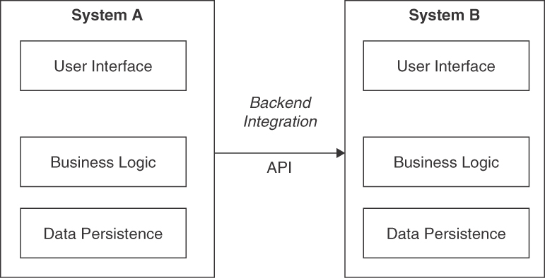
Figure 4.6 BACKEND INTEGRATION sketch 1: System-to-system message exchange
Figure 4.7 illustrates the second usage context of the pattern, application-internal decomposition of business logic into service components exposing a SOLUTION-INTERNAL API.
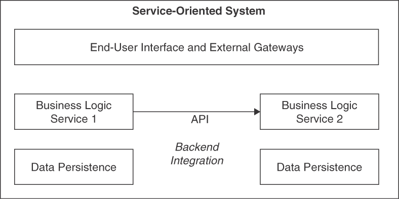
Figure 4.7 BACKEND INTEGRATION sketch 2: Microservices communicating via SOLUTION-INTERNAL API
The entry to the business logic layer is a suitable location for a BACKEND INTEGRATION API. Access control, authorization enforcement, system transaction management, and business rule evaluation typically are already located here. In some data-centric scenarios not requiring much logic, it may make sense to integrate on the data persistence layer instead (this is not shown in Figure 4.7).
Details
Decide on the visibility of the integration API: the options are PUBLIC API, COMMUNITY API, and SOLUTION-INTERNAL API. Compose the request and, optionally, response messages of the API operations from one or more ATOMIC PARAMETERS, possibly nested in PARAMETER TREES (discussed further under “Basic Structure Patterns”). Define the roles of the API endpoints in the BACKEND INTEGRATION and the responsibilities of their operation (Chapter 5). Design the messages in detail with element stereotypes and quality improvement patterns (Chapters 6 and 7). Consciously decide if and how to version the integration API over its lifetime (Chapter 8) when doing so. Create an API DESCRIPTION and supplemental information (Chapter 9).
Apply a systematic approach to application landscape planning (systems of systems design). Consider strategic domain-driven design (DDD) [Vernon 2013] as a light approach to enterprise architecture management (“software city planning”). To decompose a single system into services, apply cutting criteria derived from functional requirements and domain model [Kapferer 2021, Gysel 2016] and operational requirements such as scaling needs and developmental concerns such as independent changeability [Zimmermann 2017]. Also, consider cloud cost and workload patterns [Fehling 2014].
To promote interoperability, choose a mature remoting technology that supports standard messaging protocols and established message exchange formats. In addition to those listed as options to realize FRONTEND INTEGRATION, asynchronous, queue-based messaging is often used in BACKEND INTEGRATIONS (especially those integrating separate systems); see discussion in Chapter 1 for rationale and examples.
 Pattern: PUBLIC API
APIs exposed to the World Wide Web do not aim to limit their target audience and accessibility but often control access to them with API KEYS.
How can an API be made available to an unlimited and/or unknown number of API clients outside the organization that are globally, nationally, and/or regionally distributed?
Expose the API on the public Internet along with a detailed API DESCRIPTION that describes both functional and nonfunctional properties of the API.
Figure 4.8 sketches the PUBLIC API pattern in an exemplary scenario.
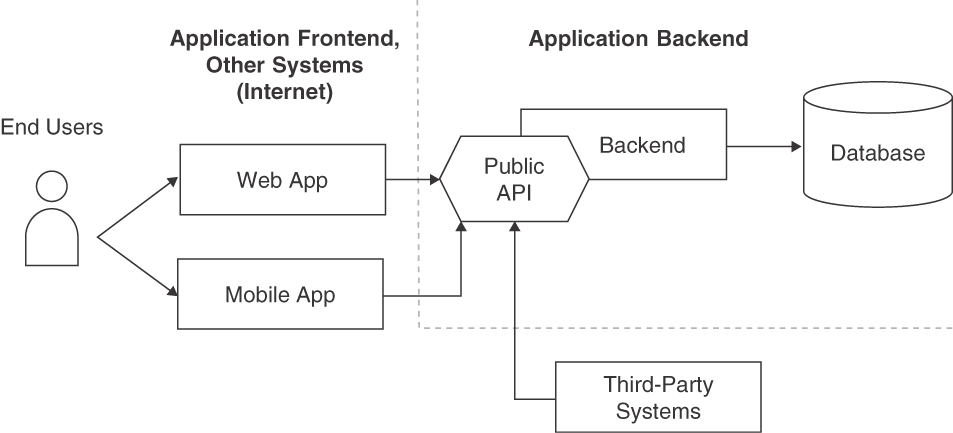
Figure 4.8 API visibilities: PUBLIC API in context
Details
Specify the API endpoints, operations, message representations, quality-of-service guarantees, and life-cycle support model. Continue this integration design by choosing responsibility patterns and choosing one or more evolution patterns (from Chapters 5 and 8). For instance, mark the API as a PROCESSING RESOURCE, introduce VERSION IDENTIFIERS, and apply SEMANTIC VERSIONING.
Use API KEYS (Chapter 7) or other security means to control access to the API. Harden the API from a security and reliability perspective, and also invest in the quality of API DESCRIPTION and support procedures (Chapter 9). From an API economy point of view, define a PRICING PLAN and implement billing/subscription management. Consider introducing RATE LIMITS for free plans. Document API usage terms and conditions, for instance, in a SERVICE LEVEL AGREEMENT, and let API consumers agree to them as a prerequisite to using the API. Cover fair use and indemnification in these terms and conditions.5 These patterns are covered in Chapter 9.
5. Being legally binding artifacts, terms and conditions documents and SERVICE LEVEL AGREEMENTS of PUBLIC APIS should be written or at least reviewed and approved by professionals specializing in legal matters.
 Pattern: COMMUNITY API
Some APIs are shared by clients in different organizations and might be deployed in and accessible via networks available only to community members.
How can the visibility of and the access to an API be restricted to a closed user group that does not work for a single organizational unit but for multiple legal entities (such as companies, nonprofit/nongovernment organizations, and governments)?
Deploy the API and its implementation resources securely in an access-restricted location so that only the desired user group has access to it—for instance, in an extranet. Share the API DESCRIPTION only with the restricted target audience.
Figure 4.9 sketches the COMMUNITY API pattern in its architectural context.
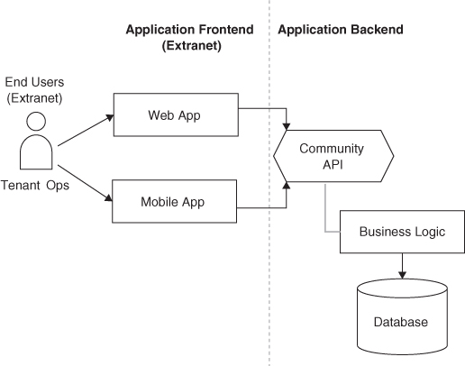
Figure 4.9 API visibilities: COMMUNITY API in context
Details
Specify the API in terms of its endpoints, operations, message representations, quality of service guarantees, and life-cycle model. Refer to the solution details of PUBLIC API for more comprehensive (equally valid) hints and related patterns.
Harden the API from a security and reliability perspective, and invest in the quality of API DESCRIPTION and support procedures (including community-managed member support). Appoint a communitywide API owner and seek shared funding.
This pattern combines elements from its sibling visibility patterns PUBLIC API and SOLUTION-INTERNAL API (and can be seen as a hybrid of these two patterns). For instance, it may define a community-specific pricing model (in an approach similar to that for a PUBLIC API), but also may consider colocation of API endpoints and their implementations (as many SOLUTION-INTERNAL APIS do).
 Pattern: SOLUTION-INTERNAL API
Some APIs structure applications into components, for instance, services/microservices or program-internal modules. In such cases, API clients and their providers often run in the same data center or even on the same physical or virtual compute node.
How can access to and usage of an API be limited to an application, for instance, components in the same or another logical layer and/or physical tier?
Decompose the application logically into components. Let these components expose local or remote APIs. Offer these APIs only to system-internal communication partners such as other services in the application backend.
Figure 4.10 sketches two instances of the SOLUTION-INTERNAL API pattern, supporting an application frontend and another backend component, with sample API clients and backend implementation.
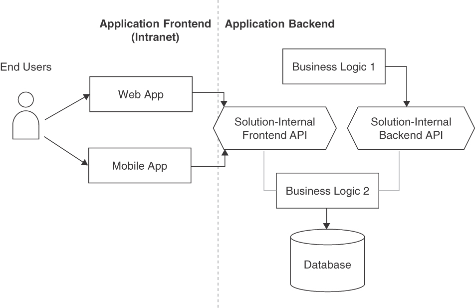
Figure 4.10 API visibilities: SOLUTION-INTERNAL API
Details
A collection of related SOLUTION-INTERNAL APIS sometimes is referred to as Platform API. For instance, all Web APIs exposed in a single cloud provider offering (or collections of such offerings) qualify as platform APIs; examples include APIs in Amazon Web Services storage offerings and in Cloud Foundry. The same holds for all SOLUTION-INTERNAL APIS within a software product such as a message-oriented middleware; the endpoint and management APIs in ActiveMQ and RabbitMQ may serve as examples of such platform APIs.
Note that independent deployability does not have to imply independent deployment. A modular monolith [Mendonça 2021], for instance, uses plain messages exchanging data transfer objects via local APIs; such a modular monolith can be turned into a microservices-based system more easily than an object-oriented “instance jungle” with tight couplings between the objects at runtime caused by call-by-reference between remote methods and distributed garbage collection.
Designing and deploying SOLUTION-INTERNAL APIS for BACKEND INTEGRATION to improve the coupling characteristics of applications and their parts is a complex undertaking; both the first wave of service-oriented architectures in the 2000s and the microservices trend that gained momentum since 2014 target this part of the design space. Many books and articles exist, including some in this series [Vernon 2021]. We come back to the topic in Chapter 5.
Foundation Patterns Summary
This concludes our coverage of five foundation patterns in this chapter. Chapter 3 features these patterns as decisions required and problem-solution pairs.
Note that FRONTEND INTEGRATION is sometimes called vertical integration, while BACKEND INTEGRATION is called horizontal integration. The notion originates from a rather common visualization of distributed systems (and their layers and tiers) that places frontends at the top of figures/model diagrams and backends at the bottom; if several systems are displayed, this is done along the x-axis of the figure. Note that a left-to-right organization of such figures also is seen frequently.
You might be wondering why we call out the integration type and API visibility in pattern form; aren’t all these APIs just APIs with endpoints, operations, and messages? They are. However, practical experience suggests that the business contexts and requirements for the two integration types are different; therefore, APIs serving frontend and backend fulfill other purposes and are designed differently. For instance, the protocol choice might differ in the two cases: HTTP often is a natural (or the only) choice in FRONTEND INTEGRATION, while message queuing is attractive in BACKEND INTEGRATION. The request and response message structures may vary too in terms of their breadth and depth. An API that does both either makes design compromises or has to offer optional features, which tends to complicate its usage. Similar concerns apply to API visibility; for instance, a PUBLIC API often has more advanced security requirements and stability needs than an internal one; the error reporting has to consider that API clients and providers might not even know each other (which is less likely for SOLUTION-INTERNAL APIS).
Next, we look at the building blocks of request and response messages, abstracting from the data definition concepts in exchange formats such as JSON.
Basic Structure Patterns
API contracts describe the unique address of one or more API endpoints (such as an HTTP resource URI), their operations (such as supported HTTP verbs or the name of a SOAP Web service operation), plus the structures of the request and response messages of each operation. The data structures defining these messages are an essential part of the API contract; the domain model in Chapter 1 features them as representation elements. Figure 4.1 presented exemplary request and response messages at the start of this chapter.
Design questions about these data structures (representation elements) arise:
What is an adequate number of representation elements for request and response messages?
How should these elements be structured and grouped?
For instance, these design issues affect the resource URI (including path parameters), query, cookie, header parameters, and message content (also called message body) when HTTP is the message exchange protocol. GET and DELETE requests usually do not contain bodies, but responses to such requests do. HTTP POSTs, PUTs, and PATCHes often contain both request and response bodies but may also define one or more path, query, header, and cookie parameters. In a WSDL/SOAP context, we can interpret this design issue as how the SOAP message parts should be organized and which data types should be used to define the corresponding XML schema elements. gRPC Protocol Buffers and GraphQL provide similar concepts to specify messages, with similar granularity decisions required.
The four patterns in this section answer the two questions differently. An ATOMIC PARAMETER describes plain data such as texts and numbers, and an ATOMIC PARAMETER LIST groups several such elementary parameters. PARAMETER TREES provide nesting (of atoms and other trees), and a PARAMETER FOREST groups multiple such tree parameters at the top level of a message. The pattern map in Figure 4.11 shows these four patterns with their relations to each other.
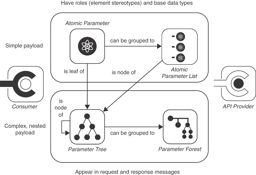
Figure 4.11 Patterns to structure messages and their representation elements
 Pattern: ATOMIC PARAMETER
Known from programming languages, basic types are the simplest unit of transmission in message exchanges between API clients and API providers (of all visibilities and integration types introduced earlier in this section).
How can simple, unstructured data (such as a number, a string, a Boolean value, or a block of binary data) be exchanged between API client and API provider?
Define a single parameter or body element. Pick a basic type from the type system of the chosen message exchange format for it. If justified by receiver-side usage, identify this ATOMIC PARAMETER with a name. Document name (if present), type, cardinality, and optionality in the API DESCRIPTION.
Decide whether the atom is single- or set-valued. Describe the meaning of the transported values, at least informally, including, for instance, a unit of measure. Consider specifying a value range to constrain the type of the ATOMIC PARAMETER. Make this value-range information explicit—statically in the schema definition language for the chosen message exchange format (for example, JSON Schema, Protocol Buffers, GraphQL Schema Language, or XML Schema) and/or dynamically in runtime metadata.
Figure 4.12 visualizes a single-valued string parameter as a single instance of the pattern appearing in a request message.
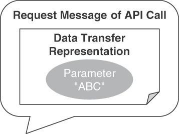
Figure 4.12 ATOMIC PARAMETER pattern: Single scalar (of basic type)
In the Lakeside Mutual sample case, ATOMIC PARAMETERS can be found in all API operations, for instance, those dealing with services concerning customer information. The first example is single-valued:
"city":Data<string>The notation of this example is Microservice Domain-Specific Language (MDSL; see Appendix C for an introduction). In the API of the Customer Core application at Lakeside Mutual, such parameters can be used to retrieve the city of a customer:
curl -X GET --header 'Authorization: Bearer b318ad736c6c844b'http://localhost:8110/customers/gktlipwhjr?fields=city{"customers": [{"city": "St. Gallen","_links": {"self": {"href": "/customers/gktlipwhjr?fields=city"},"address.change": {"href": "/customers/gktlipwhjr/address"}}}],...}
Note that city is not the only ATOMIC PARAMETER in the example. The customer identifier gktlipwhjr in the path of the URI also qualifies as such.
Atomic parameters may come as collections of basic types, which is expressed by making the atom set-valued *, as shown in the following MDSL example:
"streetAddress":D<string>*A JSON instance of the preceding definition is
{ "streetAddress": [ "sampleStreetName1", "sampleStreetName2"]}ATOMIC PARAMETERS appear in all operation definitions and in their schema components. Appendix B presents an OpenAPI specification from the Lakeside Mutual case.
Details
Expressive names from the domain that the API belongs to make the API under-standable for client developers and nontechnical stakeholders. Each atom might have an exactly-one cardinality but also be optional (zero-or-one cardinality), set-valued (at-least-one), or both (zero-or-more). Binary data might have to be encoded, for instance, in Base64 [Josefsson 2006].
Note that the texts and numbers that travel in ATOMIC PARAMETERS may actually be structured internally, for instance, if a string has to match a certain regular expression or is a collection of identically structured entries (such as the lines in the CSV format). However, this structure is not something the API provider and the API client deal with during serialization and deserialization. Preparing and processing valid data remains a responsibility of the application containing the API client and the API implementation on the provider side. The API DESCRIPTION may define certain value range and validation rules, but typically, the enforcement of these rules is not part of the interoperability contract but is an implementation-level task (as explained earlier). Note that this “tunneling” approach is sometimes perceived as an antipattern because it bypasses serialization/deserialization tools and middleware; this approach might appear to be convenient, but it introduces technical risk and, possibly, security threats.
ATOMIC PARAMETERS often play certain roles within a request or response message. Chapter 6 highlights four such roles in the section on “Element Stereotypes”: domain DATA ELEMENT, METADATA ELEMENT, ID ELEMENT, and LINK ELEMENT.
 Pattern: ATOMIC PARAMETER LIST
Sometimes, a single ATOMIC PARAMETER is not expressive enough. Two or more such ATOMIC PARAMETERS might have strong semantic ties, or the content of a request or response message might need several parts that are worth distinguishing from an API client, API provider, or intermediary point of view.
How can multiple related ATOMIC PARAMETERS be combined in a representation element so that each of them stays simple, but their relatedness becomes explicit in the API DESCRIPTION and the runtime message exchanges?
Group two or more simple, unstructured data elements in a single cohesive representation element to define an ATOMIC PARAMETER LIST that contains multiple ATOMIC PARAMETERS. Identify its items by position (index) or by a string-valued key. Identify the ATOMIC PARAMETER LIST as a whole with its own name as well if that is needed to process it in the receiver. Specify how many elements are required and permitted to appear.
The ATOMIC PARAMETER LIST as a whole, but also its elements, can be optional or set-valued. These properties should be expressed as cardinalities in the API DESCRIPTION.
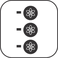
Figure 4.13 sketches an application of the pattern in a request message. The data transfer representation in the figure has three ATOMIC PARAMETER entries.
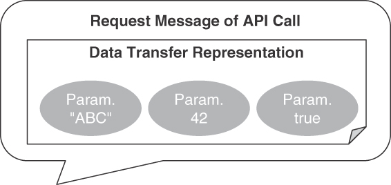
Figure 4.13 ATOMIC PARAMETER LIST pattern: Grouped atoms
In the Lakeside Mutual case, an ATOMIC PARAMETER LIST may represent customer addresses (MDSL notation):
data type AddressRecord ("streetAddress":D<string>*,"postalCode":D<int>?,"city":D<string>)
The streetAddress is set-valued, indicated by the asterisk *. The postalCode is marked as optional in this example, indicated by the question mark ?.
A JSON representation of sample data adhering to this definition is
{"street": ["sampleStreetName"],"postalCode": "42","city": "sampleCityName"}
Revisiting the Customer Core example from the ATOMIC PARAMETER, it might be required to specify multiple fields in the request. In that case, a single fields=city,postalCode parameter, which is an ATOMIC PARAMETER LIST, allows the API client to indicate that it wants the provider to include certain (but not all) fields in the response:
curl -X GET --header 'Authorization: Bearer b318ad736c6c844b'http://localhost:8110/customers/gktlipwhjr?fields=city,postalCode
The client does not identify the individual fields by a key but by position in the GET request. The provider iterates through the list to decide whether or not to include a field in the response. This, in fact, is the essence of an API quality pattern called WISH LIST (presented in Chapter 7).
Details
Design advice for single ATOMIC PARAMETERS is applicable here too; for instance, the parameters should be named in a meaningful and consistent way; the chosen names should be part of the domain vocabulary. The order of the atoms in the list should be logical and express the proximity of the elements to improve human readability. The API DESCRIPTION should provide representative examples for the permitted combinations (instances of valid lists, that is).
Some platforms do not allow the communication participants to send multiple scalars in a particular message type. For instance, many programming languages allow only one return value or object in a response message; the default mappings from these languages to JSON and XML schema follow this convention (for example, JAX-RS and JAX-WS in Java). The pattern cannot be used in that case; a PARAMETER TREE has the required expressivity.
 Pattern: PARAMETER TREE
Listing basic representation elements in a flat ATOMIC PARAMETER LIST that by definition contains only plain ATOMIC PARAMETERS often is not sufficient, for instance, when publishing rich domain data such as an order that contains order items or products that are sold to many customers (that in turn buy many products).
How can containment relationships be expressed when defining complex representation elements and exchanging such related elements at runtime?
Define a PARAMETER TREE as a hierarchical structure with a dedicated root node that has one or more child nodes. Each child node may be a single ATOMIC PARAMETER, an ATOMIC PARAMETER LIST, or another PARAMETER TREE, identified locally by a name and/or by position. Each node might have an exactly-one cardinality but also a zero-or-one cardinality, an at-least-one cardinality, or a zero-or-more cardinality.
Note that the pattern is defined recursively to yield the desired nested structures. In HTTP APIs, nested JSON objects provide the tree structure expressed by this pattern; set-valued tree nodes can be represented with JSON arrays containing JSON objects corresponding to the nodes.
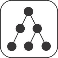
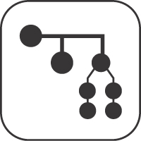
Figure 4.14 illustrates the pattern conceptually.
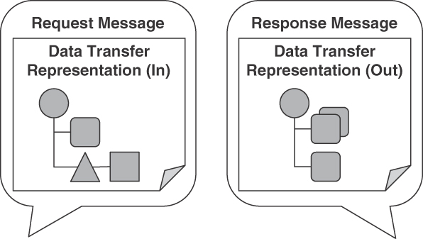
Figure 4.14 PARAMETER TREE pattern: Two versus one nesting level
In the Lakeside Mutual case, PARAMETER TREES can be found in several API operations that deal with customer and contract data. Picking up the example in Figure 4.1 at the beginning of this chapter, an example of a two-level nesting is as follows (note that the AddressRecord in the example has already been defined as an ATOMIC PARAMETER LIST above):
data type MoveHistory {"from":AddressRecord, "to":AddressRecord, "when":D<string>}data type CustomerWithAddressAndMoveHistory {"customerId":ID<int>,"addressRecords":AddressRecord+, // one or more"moveHistory":MoveHistory* // type reference, collection}
This MDSL data definition CustomerWithAddressAndMoveHistory might produce the following JSON object-array structure at runtime:
{"customerId": "111","addressRecords": [{"street": "somewhere1","postalCode": "42","city": "somewhere2"}],"moveHistory": [{"from": {"street": "somewhere3","postalCode": "44","city": "somewhere4"},"to": {"street": "somewhere1","postalCode": "42","city": "somewhere2"},"when": "2022/01/01"}]}
The MDSL Web site6 provides more examples.
6. https://microservice-api-patterns.github.io/MDSL-Specification/datacontract
Details
If the structure of the domain model element(s) represented as parameters is hierarchical or associative (with 1:1 relations such as customer overview and details or n:m relations such as customers buying products), then using PARAMETER TREE is a natural choice that is beneficial for understandability compared to other options, such as representing the complex structure in a flattened list. If additional data (such as security information) has to be transmitted with the message, the hierarchical nature of a PARAMETER TREE can set the additional data structurally apart from the domain parameters and is thus well suited for this use case (CONTEXT REPRESENTATION, Chapter 6).
PARAMETER TREES are more complex to process than atoms, and bandwidth may be wasted during message transfer if they contain unnecessary elements or an excessive number of nesting levels. But if the structure that needs to be transferred is a deep hierarchy, they typically are more efficient both in processing and bandwidth use than sending multiple messages with simpler structures. PARAMETER TREES introduce the risk that sometimes unnecessary information and/or more structure(s) information is shared between API client and provider, for instance, when the optionality of information is not defined explicitly. This might not be optimal with regard to format autonomy as a facet of loose coupling.
Note the recursive definition of the pattern. When applying the pattern, for instance, when defining a JSON schema for the body of an HTTP POST request, making use of such recursive definitions might be elegant (and sometimes cannot be avoided); choices and optionality of nodes give tree construction processors a chance to terminate. However, even when doing so, such recursive definitions might also lead to large message payloads that stress tools and runtime serializers such as Jackson (or even crash them).
 Pattern: PARAMETER FOREST
Just as ATOMIC PARAMETERS may form ATOMIC PARAMETER LISTS, PARAMETER TREES can also be assembled into groups. This is useful only at the top level of a request or response message header or payload.
How can multiple PARAMETER TREES be exposed as a request or response pay-load of an API operation?
Define a PARAMETER FOREST comprising two or more PARAMETER TREES. Locate the forest members by position or name.
Figure 4.15 illustrates the pattern.

Figure 4.15 PARAMETER FOREST pattern
The PARAMETER TREES in the forest are accessed by position or name; in contrast to trees that may contain other trees, PARAMETER FORESTS may not contain other forests.
data type CustomerProductForest ["customers": { "customer":CustomerWithAddressAndMoveHistory }*,"products": { "product":ID<string> }]
The JSON rendering of this specification looks very similar to that of a tree of the same structure:
{"customers": [{"customer": {"customerId": "42","addressRecords": [{"street": "someText","zipCode": "42","city": "someText"}],"moveHistory": []}}],"products": [{ "product": "someText" }]}
However, a Java interface of the service unveils the slight difference in the operation signature:
public interface CustomerInformationHolder {boolean uploadSingleParameter(CustomerProductForest newData);boolean uploadMultipleParameters(List<Customer> newCustomer, List<String> newProducts);}
The uploadSingleParameter method uses a single class CustomerProduct-Forest as its input (containing customer and product trees), while uploadMul-tipleParameters works with two parameters, of type List<Customer> and List<String>. Note that the latter can easily be refactored into the former.
Details
This pattern represents the special case of two or more nested top-level parameters (or message body elements). In most technology mappings of the pattern, it is semantically equivalent to a PARAMETER TREE with the forest members as the first nesting level (see the JSON example presented earlier).
In HTTP resource APIs, the collection of query, path, cookie parameters, and body jointly can be seen as such a forest (and is one of the reasons we have this pattern).
A PARAMETER FOREST can be turned into a PARAMETER TREE by introducing an “artificial” root node; similarly, ATOMIC PARAMETER LISTS and flat PARAMETER TREES are equivalent. Therefore, recursive PARAMETER TREES and ATOMIC PARAMETER as leaf nodes would suffice to represent arbitrarily complex data structures. One might wonder about the merit of having four distinct patterns rather than two. We decided to present four design options as patterns to be able to model the intricacies of various technologies such as HTTP, WSDL/SOAP, gRPC, and so on—without hiding their conceptual differences and without losing generality.
Basic Structure Patterns Summary
The data part of the API contract, established by the structures of request and response message payload, directly contributes to (or harms) the developer experience. Qualities such as interoperability and maintainability are at stake. Chapter 1 provides a deeper discussion of these and many more desired qualities (and related design challenges).
The use of the patterns results in platform-independent schema definitions that correspond to JSON schema (as used in OpenAPI), Protocol Buffer specifications, or GraphQL Schema Language (see Table 4.2).
Table 4.2 Basic Structure Patterns and Their Known Uses
Theme | Pattern | JSON | XML, XML Schema | Protocol Buffers | GraphQL |
|---|---|---|---|---|---|
Plain data | ATOMIC PARAMETER (single-valued) | Basic/primitive types | Simple types | Scalar value types | Scalar types |
Map/record | ATOMIC PARAMETER LIST | Object | Sequence of size 1, referencing built-in or custom types | Nested types |
|
Nesting | PARAMETER TREE | Object including other objects | Complex types | Message referencing other messages |
|
Group of nested elements | PARAMETER FOREST | Top-level array of objects | Can be modeled in WSDL (but not used in practice) | n/a | n/a |
Collection | Variant of other patterns (atoms, trees) | Array |
|
| Array |
Flat PARAMETER TREES and ATOMIC PARAMETER LISTS can be mapped to path parameters or the query string of a URI, for instance, via “deepObject” serialization [OpenAPI 2022]. This gets more difficult or might even be impossible for deeply nested trees; according to the OpenAPI Specification, the “behavior for nested objects and arrays is undefined.”
All four types of basic structure elements can be used and combined to create METADATA ELEMENTS, ID ELEMENTS, and LINK ELEMENTS as variations of general-purpose DATA ELEMENTS (patterns from Chapter 6). EMBEDDED ENTITIES often come as PARAMETER TREES, and LINKED INFORMATION HOLDERS use ATOMIC PARAMETER LISTS to define the link target (Chapter 7). A VERSION IDENTIFIER often is an ATOMIC PARAMETER (Chapter 8).
Optionally, data provenance information can be provided in the API DESCRIPTION. Such information might include the entities, people, and processes involved in producing the representation elements; the data origins; and where the data moves over time. Note that such information may increase coupling because the message receiver might start interpreting and depending on it, making the API harder to change. The element stereotypes in Chapter 6 describe how to add this and other semantic information to the representation elements: METADATA ELEMENT, ID ELEMENT, and LINK ELEMENT.
Chapter 3 covers the four basic structure patterns presented in this section with their problem-solution pairs.
Summary
In this chapter, we established the scope of our pattern language, introduced its organization, and discussed possible navigation paths. We also introduced five foundation and four basic structure patterns not covered in depth later in the book.
The patterns capture proven solutions to design problems commonly encountered when specifying, implementing, and maintaining message-based APIs. To ease navigation, the patterns are grouped by life-cycle phase, scope, and category of design concern. Each pattern in the following chapters is described following a common template, progressing from context and problem to solution and example to discussion and related patterns.
The basic building blocks of our pattern language were introduced in this chapter, starting from PUBLIC API for FRONTEND INTEGRATION to COMMUNITY API and SOLUTION-INTERNAL API for FRONTEND INTEGRATION and BACKEND INTEGRATION to flat and nested message structures including ATOMIC PARAMETERS and PARAMETER TREES.
Once it has been decided which type of API to build and where to expose it, end-points and their operations can be identified. Assigning endpoint roles and operation responsibilities helps with that, which is the topic of Chapter 5. The message and data contract design continues in Chapter 6. LINKED INFORMATION HOLDER and EMBEDDED ENTITY are two more of the 44 patterns in this book. They served as examples at the start of this chapter, and we return to them in Chapter 7.