
4The Geometry of Image Formation
Interaction of Light with Matter
Imaging generally records the interaction of light or radiation with the subject, except for self-luminous or emissive subjects and uses lenses or optical systems to form an image at the photoplane of a camera. There are four principal effects of the interaction of light with an object, namely absorption, reflection, transmission, and chemical change. The first two of these always occur to some extent: transmission occurs in the case of translucent or transparent matter; and chemical change occurs under appropriate circumstances. The absorbed light energy is not destroyed, but converted to another such as heat, or sometimes electrical or chemical energy. This chapter details the behaviour of reflected or transmitted light, and the formation of an optical image.
Transmission
Some transparent and translucent materials allow light to pass completely through them apart from absorption losses. Such light is said to be transmitted and the transmittance (T) of the material is the ratio of emergent luminous flux to incident luminous flux. Direct transmission (sometimes miscalled ‘specular transmission’) refers to light transmitted without scatter, as for example by clear optical glass. If selective absorption takes place for particular wavelengths of incident white light, then the material is seen as coloured by transmitted light, as in the case of a camera filter. If scattering occurs, as in a translucent medium, the light undergoes diffuse transmission, which may be uniform or directional or preferential. The transmittance of such a medium may be defined as in either a general or in a specific direction.
Reflection
Depending on the nature of the surface, particularly its smoothness, the reflection of light may be direct or diffuse. Direct or specular reflection is the type of reflection given by a highly polished surface such as a mirror, and is subject to the laws of reflection (Figure 4.1). Light incident on the surface is reflected at an angle equal to the angle of incidence. (The angles of incidence and reflection are both measured from the normal, i.e. the line perpendicular to the surface at the point of incidence.) The surface brightness of a directly reflecting surface is highly dependent on viewpoint. A perfectly diffuse or Lambertian surface, on the other hand, reflects the incident light equally in all directions; thus its brightness or luminance is seen as constant irrespective of viewpoint. Few surfaces have such extreme properties; shiny surfaces usually produce some scattered light, and matt surfaces (Figure 4.2) may show a ‘sheen’. Reflection from most surfaces combines both direct and diffuse reflection and is known as mixed reflection. Depending on the properties of the incident light, the nature of the material and angle of incidence, the reflected light may also be partially or completely polarized. Objects are seen mainly by diffusely reflected light which permits the perception of detail and texture, qualities not found in specular surfaces such as mirrors.
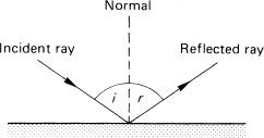
Figure 4.1Specular reflection of an incident light ray by a plane mirror; i = r
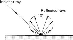
Figure 4.2The diffuse reflection of an incident light ray by a matt surface
Reflectance (R) is defined as the ratio of the reflected luminous flux to the incident luminous flux, and (as with transmittance) this may be defined as either general or in a specific direction. Surfaces commonly encountered have reflectances in the range 0.02 (2 per cent) (matt black paint) to 0.9 (90 per cent).
Refraction
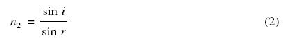
When a ray of light being transmitted in one medium passes into another of different optical properties its direction is changed at the interface except in the case when it enters normally, i.e. perpendicular to the interface. This deviation, or refraction of the ray results from a change in the velocity of light in passing from one medium to the next (Figure 4.3). Lenses utilize the refraction of glass to form images. Light travels more slowly in a denser medium, and a decrease (increase) in velocity causes the ray to be bent towards (away from) the normal. The ratio of the velocity in empty space to that within the medium is known as the refractive index (n) of the medium. For two media of refractive indices n1 and n2 where the angles of incidence and refraction are respectively i and r, then the amount of refraction is given by Snell’s Law:
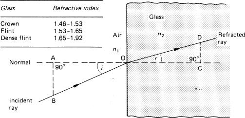
Figure 4.3An obliquely incident light ray undergoing refraction when passing from air to glass
![]()
Taking n1 as being air of refractive index approximately equal to 1, then the refractive index of the medium n2 is given by
The velocity of light in an optical medium depends on its wavelength, and refractive index varies in a non-linear manner with wavelength, being greater for blue light than for red light. A quoted value for refractive index (nλ) applies only to one particular wavelength. The one usually quoted (nd) refers to the refractive index at the wavelength of the d line in the helium spectrum (587 nm).
When light is transmitted by clear optical glass solids or prisms, refraction causes effects such as deviation, dispersion and total internal reflection (Figure 4.4). Deviation is the change of direction of the emergent ray with respect to the direction of the incident ray. In the case of a parallel-sided glass block, the emergent ray is not deviated with respect to the original incident ray; but it is displaced, the amount depending on the angle of incidence and the thickness of the block and its refractive index. A non-parallel-sided prism deviates the ray by two refractions, the deviation D depending on the refracting angle A of the prism, and on its refractive index. But when white light is deviated by a prism it is also dispersed to form a spectrum. The dispersive power of a prism is not directly related to its refractive index and it is possible to almost neutralize dispersion by using two different types of glass together, whilst retaining some deviation. In achromatic lenses this allows rays of different wavelengths to be brought to a common focus (see Chapter 6).
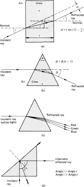
Figure 4.4Various consequences of refraction of light by glass prisms. (a) A monochromatic light ray passing obliquely through a parallel-sided glass block, and resultant displacement d. (b) Refraction of monochromatic light caused by its passage through a prism, and resultant deviation D. (c) Dispersion of white light by a prism. (d) Total internal reflection in a right-angled prism, critical angle C
For a ray of light emerging from a dense medium of refractive index n2 into a less dense medium of refractive index n1, the angle of refraction is greater than the angle of incidence, and increases as the angle of incidence increases until a critical value (ic) is reached. At this angle of incidence the ray will not emerge at all, it will undergo total internal reflection (TIR).
At this critical angle of incidence, ic = sin–1 (n1/n2). For air (n1 = 1), also for glass with n2 = 1.66, ic is 37 degrees. TIR is used in reflector prisms to give almost 100 per cent reflection as compared with 95 per cent at best for uncoated front-surface mirrors. A 45 degree prism will deviate a collimated (i.e. parallel) beam through 90 degrees by TIR; but for a widely diverging beam the angle of incidence may not exceed the critical angle for the whole beam, and it may be necessary to metallize the reflecting surface.
Image Formation
When light from a subject passes through an optical system, the subject may appear to the viewer as being in a different place (and probably of a different size). This is due to the formation of an optical image. An optical system may be as simple as a plane mirror or as complex as a highly corrected camera lens. A simple method of image formation is via a pinhole in an opaque material (Figure 4.5). Two properties of this image are that it is real, i.e. it can be formed on a screen as rays from the object pass through the pinhole, and that, as light travels in straight lines, the image is inverted, and laterally reversed left to right as viewed from behind a scattering (focusing) screen. The ground-glass focusing screen of a technical camera when used with a pinhole shows such an image.
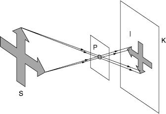
Figure 4.5Formation of an image by a pinhole. The bundles of rays from points on the subject S pass through pinhole P and diverge to form an image I on photoplane surface K. The image is inverted, reversed, smaller and lacks sharpness
A pinhole is limited in the formation of real images, as the sharpness depends on the size of the pinhole. The optimum diameter (K) for a pinhole is given by the approximate formula:
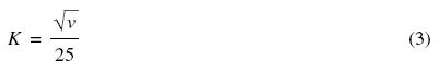
where v is the distance from pinhole to screen. A larger hole gives a brighter but less sharp image. A smaller hole gives a less bright image, but this is also less sharp owing to diffraction (see Chapter 6). Although a pinhole image does not suffer from curvilinear distortion, as images produced by lenses may do, its poor transmission of light and low resolution both limit its use to a few specialized applications.
widely diverging beam the angle of incidence may not exceed the critical angle for the whole beam, and it may be necessary to metallize the reflecting surface.
A lens is a system of one or more pieces of glass or elements with (usually) spherical surfaces, all of whose centres are on a common axis, the optical (or principal) axis. A simple or thin lens is a single piece of glass or element whose axial thickness is small compared with its diameter, whereas a compound or thick lens consists of several air spaced components, some of which may comprise several elements cemented together, to correct for aberrations. A simple lens may be regarded as a number of prisms, as shown in Figure 4.6. Light diverging from a point source P1 and incident on the front surface of the positive lens is redirected by refraction to form a real image at point P2. These rays are said to come to a focus. Alternatively, by using a negative lens, the incident rays may be further diverged by the refraction of the lens, and so appear to have originated from a virtual focus at point P3.
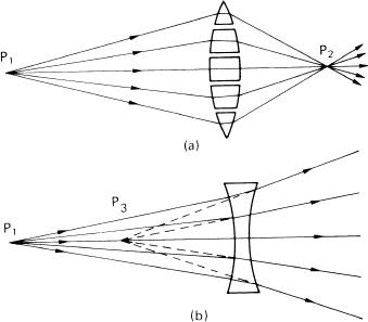
Figure 4.6Negative and positive lenses. (a) A simple positive lens considered as a series of prisms. (b) Formation of a virtual image of a point object by a negative lens
The front and rear surfaces of the lens may be convex, concave or plane; the six usual configurations of simple spherical lenses are shown in cross-section in Figure 4.7. A meniscus lens is one in which the centres of curvature of the surfaces are both on the same side of the lens. Simple positive meniscus lenses are used as close-up lenses for cameras. While the same refracting power in dioptres is possible with various pairs of curvatures, the shape of a close-up lens is important in determining its effect on the quality of the image given by the lens on the camera.
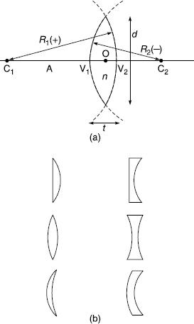
Figure 4.7Simple lens. (a) Lens parameters; A, optical axis; C1, C2, centres of curvature with radii R1 and R2; V1 and V2, vertices of spherical surfaces; O, optical centre; n, refractive index; t, axial thickness; D, diameter. (b) Shape configurations: plano-convex, plano-concave, equi-biconvex, equi-biconcave, positive meniscus, negative meniscus
The relationships between the various parameters of a single-element lens of refractive index nd, axial thickness q and radii of curvature of the surfaces R1 and R2 required to give a focal length f or (refractive) power K are given by the general ‘lensmakers’ formula’:
For f measured in millimetres, power K = 1000/f in dioptres. For a thin lens, equation (4) simplifies to
Image Formation by a Simple Positive Lens
Irrespective of their configuration of elements, camera lenses are similar to simple lenses in their image-forming properties. In particular, a camera lens always forms a real image if the object is at a distance of more than one focal length. The formation of the image of a point source has been discussed, now let us consider the formation of the image of an extended object.
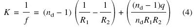
If the object is near the lens, the position and size of the optical image can be determined from the refraction of light diverging to the lens from two points at opposite ends of the object. Figure 4.8 shows this for a simple lens. The image is inverted, laterally reversed, minified, behind the lens and real.
Figure 4.8Image formation by a positive lens. (a) For a distant subject: F is the rear principal focal plane; (b) for a near subject: focusing extension E = (v – f); I is an inverted real image
To a first approximation, a distant object can be considered as being located at infinity. The rays that reach the lens from any point on the object are effectively parallel. As before the image is formed close to the lens, inverted, laterally reversed and real. The image plane in which this image is formed is termed the principal focal plane (F). For a flat distant object and an ‘ideal’ lens, every image point lies in this plane. The point of intersection of the focal plane and the optical axis is termed the rear principal focus (or simply the focus) of the lens, and the distance from this point to the lens is termed the focal length (f) of the lens. Only for an object at infinity does the image distance or conjugate (v) from the lens correspond to the focal length. As the object approaches the lens (i.e. object distance u decreases), the value of v increases (for a positive lens). If the lens is turned round, a second focal point is obtained; the focal length remains the same. The focal lengths of thick lenses are measured from different points in the lens configuration (see below). Finally, the distance of the focus from the rear surface of a lens is known as the back focus or back focal distance. This is of importance in camera design so that optical devices such as reflex mirrors or beam-splitting prisms can be located between lens and photoplane.
Image Formation by a Compound Lens
A lens is considered as ‘thin’ if its axial thickness is small compared to its diameter and to the object and image distances and its focal length, so that measurements can be made from the plane passing through its centre without significant error (Figure 4.9a). With a compound lens of axial thickness that is a significant fraction of its focal length, these measurements plainly cannot be made simply from the front or back surface of the lens or some point in between. However, it was proved by Gauss that a thick or compound lens could be treated as an equivalent thin one, and thin-lens formulae used to compute image properties, provided that the object and image conjugate distances were measured from two theoretical planes fixed with reference to the lens. This is referred to as Gaussian optics, and holds for paraxial conditions, i.e. for rays whose angle of incidence to the optical axis is less than some 10 degrees.
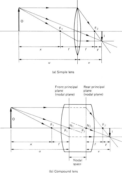
Figure 4.9Image formation by simple and compound lenses. (a) For a simple lens, distances are measured from the optical centre of the lens; distance y is the focusing extension. (b) For a compound lens, distances are measured from the principal or nodal planes (the principal planes coincide with the nodal planes when the lens is wholly in air)
Gaussian optics uses six defined cardinal or Gauss points for any single lens or system of lenses. These are two principal focal points, two principal points and two nodal points. The corresponding planes through these points orthogonal to the optical axis are called the focal planes, principal planes and nodal planes respectively (Figure 4.9b). The focal length of a lens is then defined as the distance from a given principal point to the corresponding principal focal point. So a lens has two focal lengths, an object focal length and an image focal length; these are, however, usually equal (see below).
The definitions and properties of the cardinal points are as follows:
- Object principal focal point (F1): The point whose image is on the axis at infinity in the image space.
- Image principal focal point (F2): The point occupied by the image of an object on the axis at infinity in the object space.
- Object principal point (P1): The point that is a distance from the object principal focal point equal to the object focal length F1. All object distances are measured from this point.
- Image principal point (P2): The point at a distance from the image principal focal point equal to the image focal length F2. All image distances are measured from this point. The principal planes through these points are important, as the thick lens system can be treated as if the refraction of the light rays by the lens takes place at these planes only. An important additional property is that they are planes of unit magnification for conjugate rays.
- Object nodal point (N1) and
- Image nodal point (N2) These are a pair of planes such that rays entering the lens in the direction of the object nodal point leave the lens travelling parallel to their original direction as if they came from the image nodal point. Any such ray is displaced but not deviated. If a lens is rotated a few degrees about its rear nodal point the image of a distant object will remain stationary. This property is used to locate the nodal points, and is the optical principle underlying one form of panoramic camera.
If the lens lies wholly in air, the object and image focal length of the numerous elements in the configuration (known as the effective or equivalent focal length) are equal, and the positions of the principal and nodal points coincide. This considerably simplifies imaging calculations. The value of Gaussian optics is that if the positions of the object and cardinal points are known, the image position and magnification can be calculated with no other knowledge of the optical system. Positions of the cardinal points and planes can be used for graphical construction of image properties such as location and magnification.
Usually the nodal points lie within the lens, but in some types, either or both of the nodal points may be outside the lens, either in front of it or behind it. In a few cases the nodal points may actually be ‘crossed’. The distance between the nodal points is called the nodal space or hiatus; in the case of crossed nodal points this value is taken as negative.
Graphical Construction of Images
The refraction by a lens can be determined if the paths of some of the image-forming rays are traced by simple graphical means. For a positive lens four rules are used, based on the definitions of lens properties.
- A ray passing through the centre of a thin lens is undeviated.
- A ray entering a lens parallel to the optical axis, after refraction, passes through the focal point of the lens on the opposite side.
- A ray passing through the focal point of a lens, after refraction, emerges from the lens parallel to the optical axis.
- A meridional ray (one in a plane containing the optical axis), entering the front nodal plane at a height X above the axis, emerges from the rear nodal plane at the same height X above the axis on the same side and undeviated (see Figure 4.9b).
These rules (except the last) are illustrated in Figure 4.10, together with their modification to deal with image formation by negative lenses and concave and convex spherical mirrors. Image formation is shown for a range of types of lenses and mirrors. Note that in practice other surface shapes are used such as ellipsoidal and paraboloidal as well as aspheric, principally in the optics of illumination systems for projection and enlarging. Increasingly, aspheric surfaces are used in camera lenses to reduce the number of spherical surfaces otherwise required for adequate aberration correction.
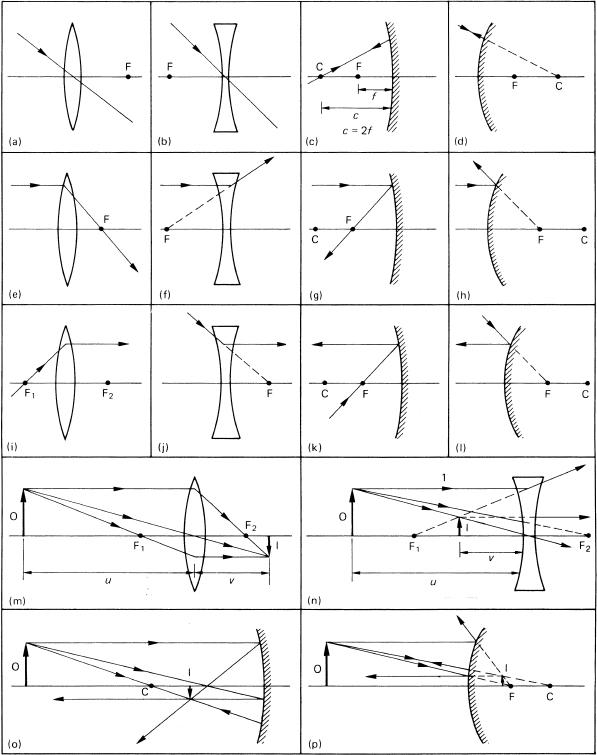
Figure 4.10The graphical construction of images formed by simple lenses and spherical mirrors. (a) A ray passing through the centre of a positive (i.e. convex) lens is undeviated. (b) A ray passing through the centre of a negative (i.e. concave) lens is undeviated. (c) A ray passing through the centre of curvature of a concave mirror is directed back upon itself. (d) A ray directed towards the centre of curvature of a convex mirror is directed back upon itself. (e) A ray travelling parallel to the optical axis of a positive lens, after refraction passes through the far focal point of the lens. (f) A ray travelling parallel to the optical axis of a negative lens, after refraction appears as if it had originated at the near focal point of the lens. (g) A ray travelling parallel to the optical axis of a concave mirror, after reflection passes through the focus of the mirror. (h) A ray travelling parallel to the optical axis of a convex mirror, after reflection appears as if it had originated from the focus of the mirror. (i) A ray passing through the near focal point of a positive lens, after refraction emerges from the lens parallel to the optical axis. (j) A ray travelling towards the far focal point of a negative lens, after refraction emerges from the lens parallel to the optical axis. (k) A ray passing through the focus of a concave mirror, after reflection travels parallel to the optical axis. (l) A ray directed towards the focus of a convex mirror, after reflection travels parallel to the optical axis. (m) An example of image construction for a positive lens using the three rules illustrated above. (n) An example of image construction for a negative lens. (o) An example of image construction for a concave mirror. (p) An example of image construction for a convex mirror
The Lens Conjugate Equation
A relationship can be derived between the conjugate distances and the focal length of a lens. With reference to Figure 4.11, a positive lens of focal length f with an object distance u forms an image at distance v.
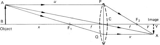
Figure 4.11Derivation of the lens equation
From similar triangles ABC and XYC,
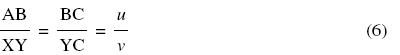
From the figure,
![]()
Also from similar triangles ABF and QCF
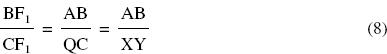
By substituting equations (6) and (7) in (8) we obtain

Rearranging and dividing by uf we obtain the lens conjugate equation
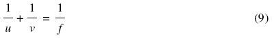
This equation may be applied to thick lenses if u and v are measured from the appropriate cardinal points.
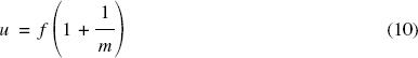
The equation is not very suitable for practical photographic use as it does not make use of object size AB or image size XY, one or both of which are usually known. Defining magnification (m) or ratio of reproduction or image scale as XY/AB = v/u, and substituting into the lens equation and solving for u and v we obtain
and
![]()
Because of the conjugate relationship between u and v as given by the lens equation above, these distances are often called the object conjugate distance and image conjugate distance respectively. These terms are usually abbreviated to ‘conjugates’.
A summary of useful lens formulae is given in Figure 4.12, including formulae for calculating the combined focal length of two thin lenses in contact or separated by a small distance. A suitable sign convention must be used. For most elementary photographic purposes the ‘real is positive’ convention is usually adopted. By this convention, all distances to real objects and real images are considered to be positive. All distances to virtual images are considered as negative. The magnification of a virtual image is also negative. An alternative Cartesian convention takes the lens or refracting surface at the origin so distances measured to the right are positive, and distances to the left are negative.
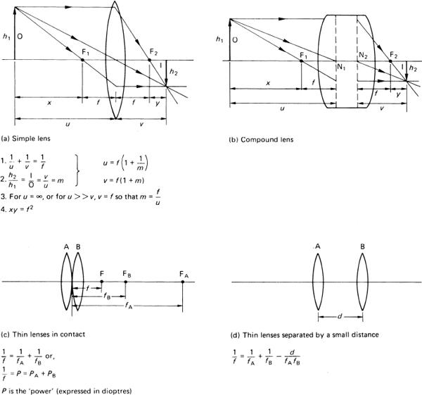
Figure 4.12Some useful lens formulae for lens calculations
It is useful to note that when the object conjugate u is very large, as for a distant subject, the corresponding value of the image conjugate v may be taken as f, the focal length. Consequently, the magnification is given by m = f/u. Thus, image magnification or scale depends directly on the focal length of the camera lens for a subject at a fixed distance. From a fixed viewpoint, to maintain a constant image size as subject distance varies a lens with variable focal length is required, i.e. a zoom lens (see Chapter 7).
Field Angle of View
The focal length of a lens also determines the angle of the field of view (FOV) relative to a given film or sensor format. The FOV is defined as the angle subtended at the (distortion-free) lens by the diagonal (K) of the format when the lens is focused on infinity (Figure 4.13).
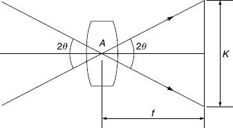
Figure 4.13Field (angle) of view (FOV) of a lens related to format dimension
Given that the FOV angle A is twice the semi-angle of view θ, then:
The field of view for a particular combination of focal length and film format may be obtained from Table 4.1. To use this table, the diagonal of the negative should be divided by the focal length of the lens; the FOV can then be read off against the quotient obtained.
Table 4.1 Table for deriving field of view of an orthoscopic lens
Diagonal/focal length (K/f) |
Field of view* (2θ) degrees |
0.35 |
20 |
0.44 |
25 |
0.54 |
30 |
0.63 |
35 |
0.73 |
40 |
0.83 |
45 |
0.93 |
50 |
1.04 |
55 |
1.15 |
60 |
1.27 |
65 |
1.40 |
70 |
1.53 |
75 |
1.68 |
80 |
1.83 |
85 |
2.00 |
90 |
2.38 |
100 |
2.86 |
110 |
3.46 |
120 |
*These values are for a lens which produces geometrically correct perspective.
As the lens to subject distance decreases, the lens to film distance increases, and the FOV decreases from its infinity-focus value. At unit magnification the FOV has approximately half its value at infinity focus.
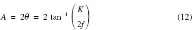
Photographic lenses can be classified according by FOV for the particular film format for which they are designed. There are sound reasons for taking as ‘standard’ a lens that has a field of view approximately equal to the diagonal of the film format. For most formats this angle will be around 52 degrees. Wide-angle lenses can have FOVs up to 120 degrees or more, and long focus lenses down to 1 degree or less. Table 4.2 gives a classification of lenses for various formats based on FOV.
Table 4.2 Lens type related to focal length and format coverage
EWA extreme wide-angle; WA wide-angle; SWA semi wide-angle; S standard; MLF medium long-focus; LF long-focus; VLF very long-focus; ELF extreme long-focus.
Occasionally confusion may arise as to the value of the FOV of a lens as quoted, because a convention exists in many textbooks on optics to quote the semi-angle θ, in which cases value given must be doubled for photographic purposes. It should also be noted that the FOV for the sides of a rectangular film format is always less than the value quoted for the diagonal. The horizontal FOV is perhaps the most useful value to quote.
The term ‘field of view’ becomes ambiguous when describing lenses that produce distortion, such as fish-eye and anamorphic objectives. In such cases it may be preferable to describe the angle subtended by the diagonal of the format at the lens as the ‘angle of the field’ and the corresponding angle in the object space as the ‘angle of view’.
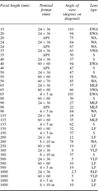
Every lens projects a fuzzy edged disc of light as the base of a right circular cone whose apex is at the centre of the exit pupil of the lens. The illumination of this disc falls off towards the edges, at first gradually and then very rapidly. The limit to this circle of illumination is due to natural vignetting as distinct from any concomitant mechanical vignetting. Also, owing to the presence of residual lens aberrations, the definition of the image within this disc deteriorates from the centre of the field outwards, at first gradually and them more rapidly. By defining an acceptable standard of image quality, it is possible to locate a boundary defining a circle of good or acceptable definition within this circle of illumination. The sensor format should be located within this region (Figure 4.14).
Figure 4.14The covering power of a lens and image format
The extent of the circle of acceptable definition also determines the practical performance of the lens as regards the covering power relative to a given format. The covering power is usually expressed as an angle of view which may be the same as or greater than that given by the format in use. A greater FOV than set by the format is called extra covering power and is essential for a lens fitted to a technical camera or a perspective-control (PC) or ‘shift’ lens when lens displacement movements are to be used. The extra covering power permits displacement of the format within the large circle of good definition until vignetting occurs, indicated by a marked decrease in luminance at the periphery of the format.
Covering power is increased by closing down the iris diaphragm of a camera lens, because mechanical vignetting is reduced, and off-axis lens aberrations are decreased by this action. The covering power of lenses for technical cameras is quoted for use at f/22 and with the lens focused on infinity. Covering power increases as the lens is focused closer; for close-up work a lens intended for a smaller format may cover a larger format, with the advantage of a shorter bellows extension for a given magnification.
Geometric Distortion
A wide-angle lens, i.e. a lens whose FOV exceeds some 75 degrees, is invaluable in many situations, such as under cramped conditions, and where use of the ‘steep’ perspective associated with the use of such lenses at close viewpoints is required. The large angle of view combined with a flat film plane (rather thanthe saucer-shaped surface that would intuitively be thought preferable), makes shape distortion of three-dimensional objects near the edge of the field of view very noticeable. The geometry of image formation by a lens over a large field is shown in Figure 4.15, producing geometrical distortion which must not be confused with the curvilinear distortion caused by lens aberrations. Flat objects are of course not distorted in this way so a wide-angle lens can be used for the copying of flat originals. As an example of the distortion occurring with a subject such as a sphere of diameter 2r, the image is an ellipse of minor diameter 2r and major diameter W, where W = 2r secθ, given unit magnification and that r is small relative to the object distance. The term secθ is the elongation factor of the image.
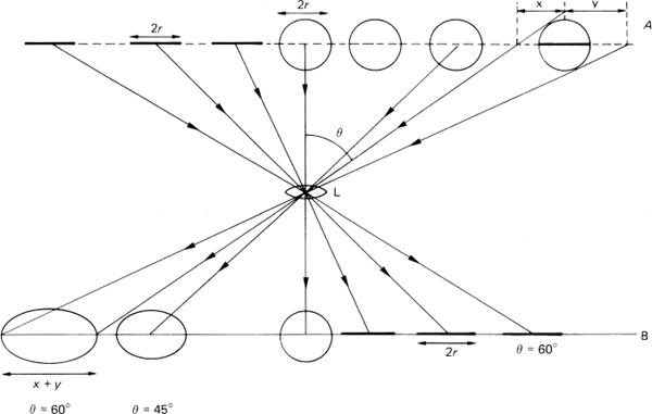
Figure 4.15Geometric distortion by a lens. An array of spheres of radius r and lines of length 2r in the subject plane A are imaged by lens L in image plane B at unit magnification. The lines retain their length independent of field angle θ but the spheres are progressively distorted into ellipses with increase in θ
Depth of Field
Image Sharpness
Any subject can be considered as made up of a large number of points. An ideal lens would image each of these as a point image (strictly, an Airy diffraction pattern) by refracting and converging the cone of light from the subject point to a focus. The purpose of focusing the camera is to adjust the image conjugate to satisfy the lens equation. The image plane is strictly correct for all object points in a conjugate plane, provided all points of the object do lie in a plane. Unfortunately, objects in practice do not usually lie in a plane, and so the image also does not lie in a single plane. Consider just two of the planes through the object (Figure 4.16). For an axial point in both planes, each point can be focused in turn but both cannot be rendered sharp simultaneously. When the image of one is in focus the other is represented by an image patch, called more formally a blur circle. These discs or circles of confusion are cross-sections of the cone of light coming to a focus behind or in front of the surface of the film.
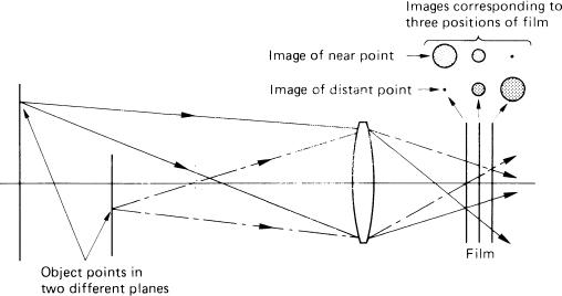
Figure 4.16Object points at different distances and their images at different photoplanes
This purely geometrical approach suggests that when photographing an object with depth, only one plane can be in sharp focus and all other planes are out of focus. Yet in practice pictures of objects are obtained with considerable depth that appear sharp all over. The reason is that the eye is satisfied with something less than pin-point sharpness. In the absence of other image-degrading factors such as lens aberrations or camera shake, a subjective measure of image quality is its perceived sharpness, which may be defined as the adequate provision of resolved detail in the image. Inspection of a photograph containing subject matter covering a considerable depth shows that the sharpness of the image does vary with depth. Detail both in front of and behind the point of optimum focus may, however, be rendered adequately sharp, giving a zone of acceptably sharp focus; this zone is termed the depth of field. (The term applies only to the object space and should not be confused with the related depth of focus, which applies to the conjugate region through the focal plane in the image space.) Depth of field is of great importance in most types of photography, the manipulation of its positioning and extent being an important creative control. Knowledge of the means of extending, restricting or simply achieving depth of field is a vital skill in practical photography.
Manipulation of a camera and lens will demonstrate the control of depth of field possible by a choice of the focal length and aperture of the lens together with the focused subject distance (Figure 4.17) for a chosen circle of confusion. The various movements of a technical camera can also be used, and described in Chapter 10.
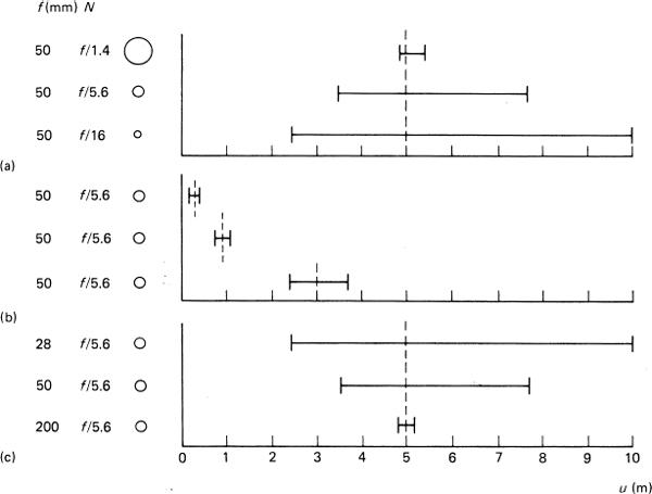
Figure 4.17Depth of field. Three variables in general influence depth of field T at a constant value for the circle of confusion. (a) Lens aperture N, varying from f/1.4 to f/16 with a 50 mm lens focused at 5 m. (b) Focused distance u, varying from 0.5 to 3 m with a 50 mm lens at f/5.6 (c) Focal length f varying from 28 to 200 mm at f/5.6 focused on 5 m
Depth of field can be quantified and calculated in terms of four variables, but first it is necessary to define ‘an acceptable standard of sharpness’ for a photographic record such as a print viewed in the hand. The depth of field boundaries are not as a rule sharply defined; usually there is a blending of acceptably sharp into less sharp detail. Much depends on the viewing conditions and also on aperture shape to some extent.
Visual Acuity
Perception of detail, judgement of its sharpness, and depth of field in a photograph depend largely upon viewing distance and visual acuity, though other factors such as image contrast and ambient illumination are also significant. Normal vision requires muscular action to alter the refractive state of the eye in order to focus. This internal focusing is called accommodation, and physiological limitations set a comfortable near distance of distinct vision (Dv) of some 250 mm. The resolving power of the eye, or visual acuity, is the ability to discriminate fine details of objects in the visual field of view, and it decreases radially. It may be specified as the width of an object at a specific distance or as the angle subtended by this object or even as the width of its retinal image that is just resolved by the eye. For example, in ideal conditions a high-contrast line of width 0.075 mm can be perceived at Dv subtending an angle of approximately 1 minute of arc, and representing an image on the retina of the eye of some 5 micrometres in width. The performance is limited by the structure of the retina, which consists of light receptors of finite size. The limiting performance is seldom achieved, and a lower value of 0.1 mm line width at Dv is commonly adopted. Converted into resolving power, an acuity of 0.1 mm corresponds to a spatial cycle of 0.2 mm, being the width of the line plus an adjacent identical space such as is used on a bar-type resolution test target, giving a value of 5 cycles per mm for the average eye. The accuracy of focusing aids such as split-image rangefinders depends upon visual acuity in aligning two parts of a subject detail with a horizontal separation or ‘split’.
Circle of Confusion
For a photograph viewed at Dv, any subject detail resolved and recorded optically that is smaller than 0.2 mm in general dimensions may not be perceptible to the unaided eye. Thus any detail finer than this size is not required. This leads to a practical definition of resolution. A limit is set to the diameter of an image blur circle that is not distinguishable from a true point (by the unaided eye), and this is called the (minimum permissible) circle of confusion (C). This is arrived at by empirical means. A photograph is viewed in a cone of vision where acceptable visual acuity is given over a FOV of some 50 to 60 degrees. The comfortable viewing area has a diameter of some 290 mm at Dv. The acceptable circle of confusion is derived from what is accepted as satisfactory definition within this area.
The obsolete ‘whole-plate’ size of 6.5 × 8.5 inches (165 × 216 mm, with a diagonal of some 270 mm), fitted neatly into the cone of vision at a distance of about 10 inches, and indeed for early photography was the usual size for contact prints for hand viewing. The standard lens for this format had a focal length of 10 inches (250 mm), and a contact print viewed at Dv gave correct perspective. A value of approximately 0.2 mm could be used for C to determine the required lens performance and depth of field.
Smaller formats, especially 24 × 36 mm, require enlargement to give a print for viewing at Dv with correct perspective (Figure 4.18). According to the ‘rules’ of perspective, a satisfactory visual rendering is given of an image corresponding spatially to the original scene when viewed at a distance equal to the focal length of the taking lens. Strictly a 24 × 36 mm image taken with a 50 mm lens should be viewed as a contact print at 50 mm, which is less than Dv. In practice an enlargement is viewed at 250 mm, but correct perspective is retained providing the proportional increase in viewing distance corresponds numerically to the degree of enlargement or print magnification M.
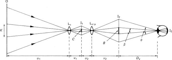
Figure 4.18Geometry of the blur circle. Subject plane O with detail K is imaged by camera lens LC at I1, then re-imaged by enlarger or projector lens Le/p at I2 and finally imaged on the retina at I3. The circle of confusion C is seen as blur circle B in the cone of vision angle θ. Visual acuity is 1/β. Relationships are: m = v1/u1, M = v2/u2, K = C/m, B = CM, β = B/Dv
Obviously the value of C in the camera image must be related to subsequent enlargement and correspondingly reduced as enlargement increases. A linear enlargement of ×8 from a 24 × 36 mm negative is common practice: it gives a resultant print of 192 × 288 mm, suited to 8 × 10 inch (203 × 254 mm) print material, a size readily viewable within the cone of vision. This implies a minimum resolving power of 40 cycles/mm or lp mm–1 for the camera lens, the product of ×8 enlargement and visual performance of 5 lp mm–1. The latter value also relates usefully to the resolving power of photographic printing paper which is approximately 6 lp mm–1.
To summarize, the permissible diameter of the circle of confusion must be reduced if subsequent enlargement is to take place. In practice values of C from 0.025 to 0.033 mm are used for the 24 × 36 mm format to allow ×8 enlargement. Values of 0.06 mm and 0.1 mm are used for medium and large formats respectively.
It is worth noting that in the early days of small-format photography a criterion of 1/1000 of the focal length of the lens was used for C, giving 0.05 mm for the 50 mm lens, which was for a long time the standard lens used for the 24 × 36 mm format, and correspondingly different values for different focal lengths. This criterion was in use for many years and is still quoted by some sources. It gives values for depth of field which imply different degrees of enlargement for different focal lengths. Some confusion has arisen on depth of field matters, especially in the provision of tables and scales, as well as comparisons between equivalent lenses from different sources. The idea of C=f/1000 is now deprecated, and instead the value of C is taken as constant for a given format, for the whole range of lenses.
Depth of Field Equations
Derivations
Useful equations for the calculation of depth of field (and depth of focus) are derived from the geometry of image formation, as shown in Figure 4.19. A lens of focal length f is focused on subject plane O, distant L from the front principal plane P1, with conjugate image plane I distant L′ from P2. Image magnification is m. The entrance and exit pupils EN and EX have diameters D and d respectively. Plane O is also distant u from EN. There are two other planes, 1 and 2, at distances R and S from EN, rays from which to EN intersect plane O in small circles of diameter K to be imaged in plane I as circles of confusion, diameter C, where C = mK.
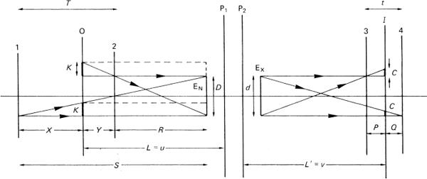
Figure 4.19Geometry of image formation for depth of field
In the object space, from similar triangles,
![]()
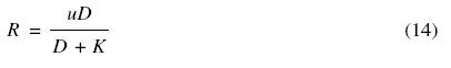
Now m = L′ /L = v/u, and the effective aperture N′ = v/D, so that D = um/N′. Taking D = uL′/N′ L and also K = CL/L′, then, substituting for D and K in equations (13) and (14),
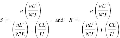
So that
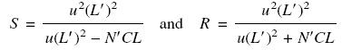
Considering the general photographic case, for distant subjects where m is less than unity, the object plane is near infinity, so we may put L′ approximately equal to f. Likewise, N′, the effective aperture, may be replaced by N, the relative aperture. For simple and symmetrical lenses, the pupils are located in the principal planes, so we may take L = u. Hence
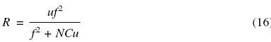
The values of S and R define the far and near limits respectively of the depth of field, when the lens is focused on distance u. The values may be tabulated in various ways, displayed in graphical form or provided as depth of field scales on the focusing mounts of lenses (Figure 4.20).
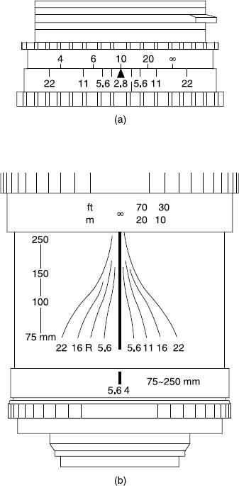
Figure 4.20Visual indication of depth of field. (a) Depth of field indicator scale. (b) Converging scales on a 75–250 mm f/4 zoom lens, including an infrared focus correction mark R
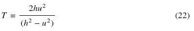
If depth of field (T) is defined as T = S − R then
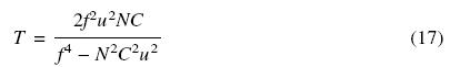
For practical purposes the N2C2u2 term in the denominator may be disregarded, so to a first approximation
This equation finds many useful applications.
Depth of field is directly proportional to the diameter of the circle of confusion, the f-number and the square of the focused distance, and inverselyproportional to the square of the focal length of the lens. Subject distance and focal length have the greatest influence; doubling the value of u increases T fourfold, while doubling focal length reduces T (at a fixed distance) by a factor of four.
It is of interest to note that equation (16) shows that a short-focus lens yields more depth of field than one of longer focus, provided that both are used to give the same magnification of a particular subject, in which case the two values of u differ. For example, using C = 0.025 mm, a lens of focal length 100 mm focused at 5 m and with an aperture of f/4 gives a magnification of 0.0204 and depth of field 501 mm. If a lens of focal length 25 mm is used, with u reduced to 1.25 m to give the same magnification, the depth of field at f/4 is now 521 mm, a little greater. However, subjective effects regarding the changed viewpoint for the subject and different performances from the two lenses can give a further subjective impression of a greater depth of field, as there is no fixed boundary that separates ‘sharp’ from ‘unsharp’.
When the subject is closer, say 2 m for the 100 mm lens and a corresponding 0.5 m for the 25 mm lens, the depth of field at f/4 is 80 mm for both lenses, so that, in theory, there should be no difference.
The differences in practice are due to the approximations and assumptions made in deriving the formulae. Use of the simplified equation (17) gives identical results in both examples. In the alternative case of a fixed viewpoint and constant u, with the value of f altered by use of zoom lens (or interchangeable lens) followed by different degrees of enlargement to give the same final print magnification, then when viewed at Dv the depth of field will be seen to remain essentially constant when the actual diameter of the aperture of the lens remains unaltered. Thus combinations of 100 mm at f/11, 50 mm at f/5.6 and 25 mm at f/2.8, all have the same depth of field for a fixed viewpoint.
Note that the use of the criterion of C = f/1000 gives different values for both lenses in the example above and would indicate that depth of field is greater for the longer focal length in such circumstances, which is incorrect.
Departures from Theory
The theory developed above assumes a truly circular circle of confusion; but this is not always so and marked departures from circular are found in anamorphic lenses, lenses with uncorrected aberrations and catadioptric (mirror) lenses. The ‘circle of confusion’ for the last of these is an annulus (caused by the central opaque disc inside the lens), and its effect can clearly be seen in out-of-focus detail. In the special case of a soft-focus lens, where under corrected spherical aberration is used to give the desired soft effect with a core of sharpness, the diameter of the blur circle cannot be defined and calculations are meaningless. The so-called deep-field lens is often incorrectly taken to mean a lens possessing enhanced depth of field, but the effect is due to anti-reflection coatings which provide increased light transmittance, so that a reduced aperture may be used for a given exposure level compared with a lens of lower transmittance. It is the smaller aperture that gives the increased depth of field, not any special correction of aberrations. In practice, for an ordinary aberration-limited lens, progressive stopping down brings the depth of field closer to predicted values until diffraction effects occur.
Hyperfocal Distance
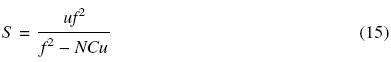
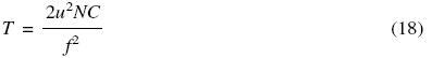
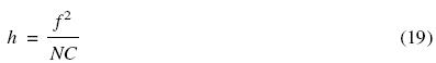
Maximum depth of field in any situation is obtained by use of the hyperfocal distance. The value of S, the far limit of T, is given by equation (15). The hyperfocal distance (h) is defined as the value of a particular focus setting u of the lens, which makes S equal to infinity. The necessary condition is f 2 = NCu; then, as u = h,
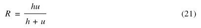
The concept of h allows simplification of equations (15) and (16) to
![]()
And likewise
From equation (21), if u equals h, then R is h/2; when u is infinity, then R equals h. So if the lens is focused at a distance u so that u equals h, then the near limit of the depth of field is h/2. This gives the maximum depth of field, from infinity to h/2, for a given aperture N.
Cameras with fixed-focus lenses have the focus set on the hyperfocal distance (for the maximum aperture if this is variable) so as to give maximum depth of field.
Close-Up Depth of Field
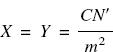
Close-up photography is defined as photography where the distance from the subject to the lens is such that magnification m is in the range 0.1 to 1.0. Referring again to Figure 4.19, the close-up depth of field T may be taken as the sum of distances X and Y, the respective distances of planes 1 and 2 from the plane of focus O, where
![]()

As these planes are close to the entrance pupil, the value of K is much smaller than D and so can be neglected in the denominators, giving
![]()
Now u/D can be replaced by N′ /m, and also C = mK, therefore
The effective aperture N′ may be replaced by N(1 + m), where N is the marked f-number. As T = X + Y, we have
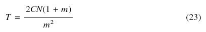
Equation (23) does not involve focal length directly, so for a given magnification a long focal length is preferable to a short focal length, as it gives a longer working distance and better perspective by virtue of its more distant viewpoint, without any change in depth of field for a given f-number. Unlike general photography, the final magnification Z in the print of the subject is usually stated. So for a print enlargement of M, Z = mM.
Depth of Focus
The term depth of focus applies only to the image space (Figure 4.21) and is the tolerance in the position of the film plane I, which depends on the acceptable diameter C of the circle of confusion (Figure 4.19). Alternatively, it may be regarded as the distance between the conjugate planes 3 and 4 either side of image plane I, corresponding to planes 1 and 2 respectively, which define depth of field. Planes 3 and 4 are distant P and Q respectively from plane I, and the cones of light from the exit pupil EX of diameter d coming to focus on planes 3 and 4 form blur circles of diameter C on plane I, which is distant v from P2, the rear principal plane. From similar triangles,
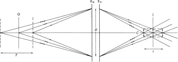
Figure 4.21Conjugate relationship between depth of field T and depth of focus t, where T = mt

But C is small compared with d and may be removed from the denominators, so
Remembering N = v/d and also N′= N(1 + m), the depth of focus (t) is the sum of P and Q, so
![]()
For general photography where m is small, equations (24) and (25) reduce to
![]()
For a large-aperture lens the depth of focus is small and the film gate or photoplane must be accurately perpendicular to the optical axis. The necessary tolerances can be relaxed for large formats where C is greater and small apertures are used; but even so, a 75 mm f/4.5 wide-angle lens used on a 4 × 5 inch format has only 0.9 mm depth of focus at full aperture (assuming C is 0.1 mm), so the position of the film surface in a dark-slide or roll film back must correspond very accurately to the plane of the focusing screen.
When a lens is focused close up, so that m has a significant value, the depth of focus is increased. The use of small apertures also increases depth of focus.
Perspective
Viewpoint
The term ‘perspective’ literally means ‘to look through’, and an accurate record of the spatial relationships of objects in a scene can be obtained by placing a glass plate, ‘the picture plane’, in the observer’s FOV, and tracing the necessary outlines on it. The reduced-size facsimile records the intersection of the projection of each subject point, converging to the centre of perspective or viewpoint (Figure 4.22), then diverging to the image plane.
Figure 4.22Elements of central perspective. In the diagram S represents the subject, I the optical image, O the centre of perspective, P the principal point, OP the principal distance, J the perspective of the subjected or picture plane, V1 and V2 the vanishing points, H the horizon line
The viewpoint is the centre of the pupil of the eye of the observer. Conventionally the picture plane is vertical, so that vertical lines in the subject remain vertical and parallel. Horizontal lines in planes parallel to the picture plane also remain horizontal and parallel, but in inclined subject planes they will converge to one or more vanishing points, positioned on the horizon line of the facsimile where the visual axis intersects it at the principal point. The orthogonal distance between the picture plane and viewpoint is the principal distance of the perspective record.
By the geometry of the situation, alteration of the principal distance alters only the size of the picture and not the perspective of the spatial relationships. However, alteration of the viewpoint in terms of distance from the subject will alter the convergence and hence alter perspective.
The perspective of the scene is correctly reconstructed only by viewing from the principal distance, which is then termed the viewing distance (D).
Camera Viewpoint
A camera records a three-dimensional scene as a two-dimensional planar image in the photoplane and in the print. By placing the camera lens at the visual viewpoint, familiar photographic parameters replace the terminology of perspective as defined above.
The convergent rays form a central perspective by passing through the lens, and continue diverging beyond the viewpoint to an image plane conjugate to the subject plane. The principal distance is now the image conjugate v, commonly taken as the focal length f for distant scenes. The facsimile or photographic record is now inverted and laterally reversed but can be contact printed and ‘flopped’ to position in the picture plane for viewing at correct distance D = v.
Various points need clarification. By altering the lens to one of longer focal length, v is increased and the image enlarged; but it retains identical perspective. So a charge of focal length for a given viewpoint does not alter perspective but only image size. By altering viewpoint by changing the object conjugate u, the perspective does change, the more obviously since a lens of large FOV may be used to include the same area of the subject from a closer viewpoint (Figure 4.23). Such ‘steep’ perspective can be used to dramatic effect. Figure 4.24 illustrates the alteration of perspective given by a change of viewpoint with a building chosen as the subject to show also two possible pictorial ‘treatments’ of the subject. A distant central viewpoint with a medium long focus lens gives an accurate view of the front elevation. A closer off-centre viewpoint with a wide- angle lens plus some rising front movement changes the shape to retain verticals, while giving more depth to the subject.
Figure 4.23Perspective in an image related to camera viewpoint and focal length. (a) Subject appearance due to reducing the viewpoint distance and increasing the field of view of the lens. (b) From a fixed viewpoint, an increase in principal distance or focal length leaves the perspective unchanged but size altered
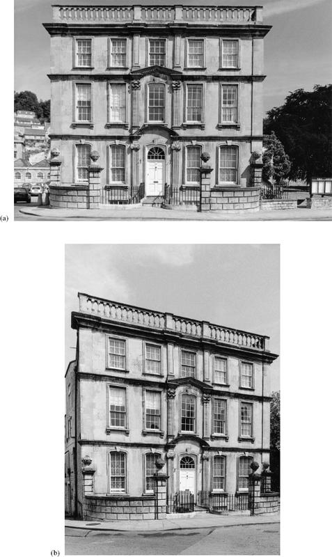
Figure 4.24Perspective and viewpoint. (a) Distant central viewpoint. (b) Closer oblique viewpoint
Perspective Distortion
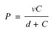
The centre of perspective or viewpoint of a camera lens is the centre of the entrance pupil for object space. The centre of the exit pupil is the centre of projection for image space. The correct viewing distance is then given by
![]()
This theoretical value of D cannot usually be used, especially if it is less than Dv. Small images need to be enlarged by magnification M for comfortable viewing and the viewing distance is then given by
![]()
For distant scenes, v is replaced by f as usual.
The correct-viewing-distance criterion is seldom observed for photographic images, prints being viewed at a convenient distance, irrespective of the values of f and M used (usually these are not known to the observer). Incorrect viewing gives rise to perspective distortions. In pictorial terms, a near viewpoint gives a ‘steep perspective’ with large changes of scale in a subject, while a distant viewpoint gives a ‘flattened perspective’ with only small changes of scale even in a subject of considerable depth. The perspective of a print viewed from too great a distance tends to appear steep, while that of a print viewed from too short a distance tends to appear flat. This is the reverse of the perspective effects achieved on taking the picture.
Bibliography
Blaker, A. (1985) Applied Depth of Field. Focal Press, Stoneham, MA.
Freeman, M. (1990) Optics, 10th edn. Butterworths, London.
Hecht, E. (1998) Optics, 3rd edn. Addison-Wesley, Reading, MA.
Jenkins, F. and White, H. (1981) Fundamentals of Optics, 4th edn. McGraw-Hill, London.
Kingslake, R. (1992) Optics in Photography. SPIE, Bellingham, WA.
Ray, S. (1984) Applied Photographic Optics, 2nd edn. Focal Press, Oxford.