
Photographs are taken by the agency of light travelling from the subject to the photoplane in the camera. This light usually originates at a source outside the picture area and is reflected by the subject. Light comes from both natural and artificial sources. Natural sources include the sun, clear sky and clouds. Artificial sources are classified by the method used to produce the light (see Table 3.1).
Table 3.1 Methods of producing light
Method |
Source of light |
Examples |
Burning |
Flame from flammable materials |
Candles, oil lamps, matches, magnesium ribbon, flash powder and flash-bulbs |
Heating |
Carbon or tungsten filament |
Incandescent electric lamps, e.g. domestic lamps, studio lamps, tungsten-halogen lamps |
Electric spark or arc |
Crater or flame of arc |
Carbon arcs, spark gaps |
Electrical discharge |
Gas or metallic vapour |
Electronic flash, fluorescent lighting, metal halide lamps |
Luminescence |
Phosphors |
Sodium and mercury vapour lamps |
Characteristics of Light Sources
Light sources differ in many ways, and the selection of suitable sources for photographic purposes is based on the order of importance of a number of significant characteristics. A summary of properties of photographic sources is given in Table 3.2. The more important characteristics are discussed in detail below.
Table 3.2 The properties of some light sources used in photography

*Correlated value
+Typical value
Spectral Quality
The radiation from most sources is a mixture of light of various wavelengths. The hue of the light from a source, or its spectral quality, may vary depending on the distribution of energy at each wavelength in its spectrum. Most of the sources used for photography emit what is usually termed white light. This is a vague term, describing light that is not visibly deficient in any particular band of wavelengths, but not implying any very definite colour quality. Most white-light sources vary considerably among themselves and from daylight. Because of the perceptual phenomenon of colour constancy these differences matter little in everyday life, but they can be very important in photography, especially when using colour materials or where there is ‘mixed’ lighting. It is essential that light quality is described in precise terms. Light is a specific region of the electromagnetic spectrum and is a form of radiant energy. Colour quality may be defined in terms of the spectral power distribution (SPD) throughout the spectrum. There are several ways this can be expressed, with varying degrees of precision. Each method has its own advantages, but not all methods are applicable to every light source.
Spectral Power Distribution Curve
Using a spectroradiometer, the spectral power distribution of light energy can be measured and displayed as the SPD curve. Curves of this type are shown in Figure 3.1 for the sun and in Figure 3.2 for some other sources. Such data show clearly small differences between various forms of light. For example, the light sources in Figure 3.1 seen separately would, owing to colour constancy effects, probably be described as white, yet the curves are different. Light from a clear blue sky has a high blue content, while light from a tungsten lamp has a high red content. Although not obvious to the eye such differences can be clearly shown by colour reversal film. Colour film has to be balanced for a particular form of lighting.

Figure 3.1Spectral power distribution curves of sunlight, light from a blue sky and light from a tungsten lamp

Figure 3.2Spectral power distribution curves typical of some of the artificial light sources used in photography
Analysis of SPD curves show that there are three main types of spectrum emitted by light sources. The sources in Figure 3.1 have continuous spectra, with energy present at all wavelengths in the region measured. Many sources, including all incandescent-filament lamps, have this type of spectrum. Other sources have the energy confined to a few narrow spectral regions. At these wavelengths the energy is high, but elsewhere it is almost nil. This is called a discontinuous or line spectrum, and is emitted typically by low-pressure discharge lamps such as sodium- and mercury-vapour lamps.
A third type of spectrum has broad bands of energy with a continuous background spectrum or continuum of varying magnitude, and is given by discharge sources by increasing the internal pressure of the discharge tube, e.g. a high-pressure mercury-vapour lamp. Alternatively, the inside of the discharge tube may be coated with ‘phosphors’ that fluoresce, i.e. emit light at longer wavelengths than the spectral lines which stimulate them. Another method is to include gases in the tubes such as xenon or argon, and metal halide vapour.
Colour Temperature
For photographic purposes a preferred method of quantifying the light quality of an incandescent source is by means of its colour temperature. This is defined in terms of what is called a Planckian radiator, a full radiator or simply a black body. This is a source emitting radiation whose SPD depends only on its temperature and not on the material or nature of the source.
The colour temperature of a light source is the temperature of a full radiator that would emit radiation of substantially the same spectral distribution in the visible region as the radiation from the light source. Colour temperatures are measured on the thermodynamic or Kelvin scale, which has a unit of temperature interval identical to that of the Celsius scale, but with its zero at –273.15 °C.
The idea of colour temperature can be appreciated by considering the progressive change in colour of the light emitted by a piece of metal as its temperature is raised, going from dull black through red and orange to white heat. The quality of the light emitted depends on the temperature of the metal. Luminous sources of low colour temperature have an SPD relatively rich in red radiation. With progression up the colour scale the emission of energy is more balanced and the light becomes ‘whiter’. At high values the SPD is rich in blue radiation. It is unfortunate that reddish light has been traditionally known as ‘warm’ and bluish light as ‘cold’, as the actual temperatures associated with these colours are the other way round.
The idea of colour temperature is strictly applicable only to sources that are full radiators, but in practice it is extended to those that have an SPD approximating to that of a full radiator or quasi-Planckian source, such as a tungsten-filament lamp. The term is, however, often applied incorrectly to fluorescent lamps, whose spectra and photographic effects can be very different from those of full radiators. The preferred term describing such sources is correlated colour temperature, which indicates a visual similarity to a value on the colour temperature scale (but with an unpredictable photographic effect, particularly with colour reversal film).
The approximate colour temperatures of light sources used in photography are given in Table 3.3.
Table 3.3 Colour temperatures of some common light sources
Light source |
Approximate colour temperature |
Mired value |
Standard candle |
1930 K |
518 |
Dawn sunlight |
2000 K |
500 |
Vacuum tungsten lamp |
2400 K |
417 |
Acetylene lamp (used in early sensitometric work) |
2415 K |
414 |
Gas-filled tungsten lamp (general service) |
2760–2960K |
362–338 |
Warm-white fluorescent lamp |
3000 K |
333 |
Photographic lamp |
3200 K |
312 |
Photoflood lamp |
3400 K |
294 |
Clear flashbulb |
3800 K |
263 |
Daylight fluorescent lamp |
4500 K |
222 |
Mean noon sunlight |
5400 K |
185 |
Photographic daylight |
5500 K |
182 |
Blue flashbulb |
6000 K |
167 |
Electronic flashtube |
6000 K |
167 |
Average daylight (sunlight and skylight combined) |
6500 K |
154 |
Colour-matching fluorescent lamp |
6500 K |
154 |
Blue sky |
12 000–18000K |
83–56 |
In black-and-white photography, the colour quality of light is of limited practical importance. In colour photography, however, it is vitally important, because colour materials and focal plane arrays (FPA) are balanced to give correct rendering with an illuminant of a particular colour temperature. Consequently, the measurement and control of colour temperature must be considered for such work, or the response of the sensor adjusted, usually termed ‘white balance’.
Colour Rendering
With fluorescent lamps, which vary greatly in spectral energy distribution, covering a wide range of correlated colour temperatures, the results given by two lamps of nominally the same properties may be quite different if used for visual colour matching or for colour photography. Various objective methods have been devised to give a numerical value to the colour rendering given by such sources as compared with a corresponding full radiator, or with visual perception. A colour rendering index (CRI) or value is defined based on the measurement of luminance in some six or eight spectral bands and compared with the total luminance, coupled with weighting factors, a value of 100 indicating ideal performance. Typical values vary from 50 for a ‘warm-white’ type to greater than 90 for a ‘colour-matching’ version.
Percentage Content of Primary Hues
For many photographic purposes, the visible spectrum can be considered as consisting of three main bands: blue, green and red. The quality of light from a source with a continuous spectrum can be approximately expressed in terms of the percentages in which light of these three hues is present. The method is imprecise; but it is the basis of some colour temperature meters, where the ratios of blue-green and red-green content are compared. (The same principles are used to specify the colour rendering given by a lens, as absorption of light at the blue end of the spectrum is common in optical glass.)
Measurement and Control of Colour Temperature
In colour photography, the colour temperature (CT) of the light emitted by all the separate sources illuminating a subject must agree in balance with that for which the process is being used. The tolerance permissible depends on the process and to some extent on the subject. A departure of 100 K from the specified value by all the sources (which may arise from a 10 per cent variation in supply voltage) is probably the maximum tolerable for colour reversal material balanced for a colour temperature of around 3200 K. Colour negative material (depending on how it is CT balanced) may allow a greater departure than this, because a certain amount of colour correction is possible at the printing stage.
A particular problem is that of mixed lighting, where part of the subject may be unavoidably illuminated by a light source of markedly different colour quality from the others. A localized colour cast may then appear in the photograph. Another example is the use of tungsten lamps fitted with blue filters to match daylight for fill-in purposes, where some mismatch can occur. Note that both blue flashbulbs and electronic flash may be used successfully as fill-in sources when daylight is the main illuminant. A visual comparison of the colour quality of two light sources is possible by viewing the independently illuminated halves of a folded sheet of white paper with its apex pointing towards the observer. Any visually observable difference in colour would be recorded in a photograph, so must be corrected (see later).
Instrumental methods such as colour temperature meters are more convenient. Most incorporate filtered photocells which sample specific regions of the spectrum, such as red, green and blue. A direct readout of colour temperature is given, usually together with recommendations as to the type of light-balancing or colour-correction filters needed for a particular type of film.
A matrix array of several hundred CCD photocells filtered to blue, green and red light, together with scene classification data can also be used in-camera to measure the colour temperature of a scene.
The CT balance of colour films to illuminants is specified by their manufacturers. The colour temperature of a lamp may be affected by the reflector and optics used; it also changes with variations in the power supply and with the age of the lamp. To obtain light of the correct quality, various precautions are necessary. The lamps must be operated at the specified voltage, and any reflectors, diffusers and lenses must be as near to neutral in colour as possible. Voltage control can be by a constant-voltage transformer. The life of filament lamps can be extended by switching on at reduced voltage and arranging the subject lighting, then using the correct full voltage only for the actual exposure. Variable resistances or solid-state dimmer devices can be used with individual lamps for trim control. To raise or lower the colour temperature by small amounts, light-balancing filters may be used over the lamps. Pale blue filters raise the colour temperature while pale yellow or amber ones lower it.
As conventional tungsten-filament lamps age, the inner side of the envelope darkens from a deposit of tungsten evaporated from the filament. Both light output and colour temperature decrease as a result. Bulb replacement is the only remedy; in general, all bulbs of a particular set should be replaced at the same time. Tungsten–halogen lamps maintain a more constant output throughout an extended life, as compared with ordinary filament lamps.
To compensate for the wide variations encountered in daylight conditions for colour photography, camera filtration may be necessary by means of light-balancing filters of known mired shift value as defined below. To use colour film in lighting conditions for which it is not balanced, colour conversion (CC) filters with large mired shift values are available (see Chapter 11).
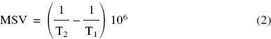
A useful method of specifying the colour balance of an incandescent source is by the mired scale, an acronym derived from micro reciprocal degree. The relationship between mired value (MV) and colour temperature (T) in kelvins is:
![]()
Figure 3.3 can be used for conversion from one scale to the other. Note that as colour temperature increases the mired value decreases and vice versa.

Figure 3.3Comparison of equivalent values on the mired and kelvin scales
The main advantage of the mired scale, apart from the smaller numbers involved, is that equal variations correspond to approximately equal visual variations in colour. Consequently, a light-balancing filter can be given a mired shift value (MSV) which indicates the change in colour quality given, regardless of the source being used. Yellowish or amber filters, for raising the mired value of the light, i.e. lowering its colour temperature in kelvins, are given positive mired shift values; bluish filters, for lowering the mired value, i.e. raising the colour temperature in kelvins, are given negative values. Thus a bluish light-balancing filter with a mired shift value of –18 is suitable for converting tungsten light at 3000 K (333 mireds) to approximately 3200 K (312 mireds). It is also suitable for converting daylight at 5000 K (200 mireds) to 5500 K (182 mireds). Most filters of this type are given values in decamireds, i.e. mired shift value divided by 10. Thus a blue daylight-to-tungsten filter of value –120 mireds is designated B12. A suitable equation for calculating the necessary MSV to convert a CT of T1 to one of T2 is
Light Output
Units
The output power of a source is an important characteristic. A source can emit energy in a wide spectral band from the ultraviolet to the infrared regions; indeed, most of the output of incandescent sources is in the infrared. For most photography only the visible region is of importance. Three related photometric units are used to define light output: luminous intensity, luminance and luminous flux.
Luminous intensity is expressed numerically in terms of the fundamental SI unit, the candela (cd). One candela is the luminous intensity in the direction of the normal to the surface of a full radiator of surface area 1/600 000 of a square metre, at the temperature of solidification of platinum. It should be noted that luminous intensity of a source is not necessarily uniform in all directions, so a mean spherical value, i.e. the mean value of luminous intensity in all directions, is sometimes used. Luminous intensity was at one time known as ‘candle-power’.
Luminance is defined as luminous intensity per square metre. The unit of luminance is the candela per square metre (cd m–2). An obsolescent unit sometimes encountered is the apostilb (asb) which is one lumen (see below) per square metre (lm m–2), and refers specifically to light reflected from a surface rather than emitted by it. The luminance of a source, like its luminous intensity, is not necessarily the same in all directions. The term luminance is applicable equally to light sources and illuminated surfaces. In photography, luminances are recorded by a film as analogue optical densities of silver or coloured dyes.
Luminous flux is a measure of the amount of light emitted into space, defined in terms of unit solid angle or steradian, which is the angle subtended at the centre of a sphere of unit radius by a surface of unit area on the sphere. Thus, an area of 1 square metre on the surface of a sphere of 1 metre radius subtends at its centre a solid angle of 1 steradian. The luminous flux emitted into unit solid angle by a point source having a luminous intensity of one candela in all directions within the angle is 1 lumen (lm). Since a sphere subtends 4π steradians at its centre (the area of the surface of a sphere is 4πr2), a light source of luminous intensity of 1 candela radiating uniformly in all directions emits a total of 4π lumens, approximately 12.5 lm (this conversion is only approximately applicable to practical light sources, which do not radiate uniformly in all directions). The lumen provides a useful measure when considering the output of a source in a reflector or other luminaire or the amount of light passing through an optical system.
Illumination Laws
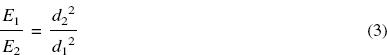
The term ‘illumination’ refers to light falling on a surface and depends on the luminous flux falling on a surface and its area. The quantitative term is illuminance or incident luminous flux per unit area of surface. The unit is the lux (lx); 1 lux is an illuminance of 1 lumen per square metre. The relationship between the various photometric units of luminous intensity, luminous flux and illumination is shown in Figure 3.4. The illumination E on a surface at a distance d from a point source of light depends on the output of the source, its distance and the inclination of the surface to the source. The relationship between illumination and distance from the source is known as the inverse square law of illumination and is illustrated in Figure 3.5. Light emitted into the cone to illuminate base area A at distance d1 with illumination E1 is dispersed over area B at distance d2 to give illumination E2. It is readily shown by geometry that if d2 is twice d1, then B is four times A, i.e. illumination is inversely proportional to the square of the distance d. Hence:

Figure 3.4Relationships between luminous intensity of a source, luminous flux and illumination on a surface

Figure 3.5The effects of the inverse square law of illumination
Also, from the definition of the lumen, the illumination in lux as given by a source at any distance from it, may be found by dividing the luminous intensity of the lamp by the square of the distance in metres. Thus the illumination on a surface 5 metres from a source of 100 candelas is 100/(5)2 = 4 lx. Recommended values of illumination for different areas range from 100 lx for a domestic lounge to at least 400 lx for a working office.
The reduced amount of illumination on a tilted surface is given by Lambert’s cosine law of illumination, which states that the illumination on an inclined surface is proportional to the cosine of the angle of incidence of the light rays falling on the surface (Figure 3.6). For a source of luminous intensity I at a distance d from a surface inclined at an angle θ, the illuminance E on the surface is given by
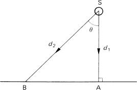
Figure 3.6Lambert’s cosine law of illumination. The illuminance E at point A distant d1 from source S of intensity I is given by E = I/d12, but at point B on the same surface receiving light obliquely the reduced illuminance is given by E = I cos θ/d22

The inverse square law strictly applies only to point sources. It is approximately true for any source that is small in proportion to its distance from the subject. The law is generally applicable to lamps used in shallow reflectors, but not deep reflectors. It is not applicable to the illumination provided by a spotlight due to the optical system used to direct the light beam.
Reflectors and Luminaires
Most light sources are used with a reflector, which may be an integral part of the lamp or a separate item. A reflector has a considerable influence on the properties of the lighting unit as regards distribution of illumination or evenness and colour of the light. The design of the reflector and housing or ‘luminaire’ of a light source is important for uniformity and distribution of illumination over the area of coverage of the lamp. Reflectors vary in size, shape and nature of surface. Some are flat or very shallow, others deeply curved in spherical or paraboloidal form. The surface finishes vary from highly polished to smooth matt or even lenticular. Some intermediate arrangement is usually favoured to give a mixture of direct and diffuse illumination. An effective way of showing the light distribution of a source plus reflector or optical system is to plot the luminous intensity in each direction in a given horizontal plane through the source as a curve in polar coordinates, termed a polar distribution curve (Figure 3.7). In this figure the source is at the origin (0°) and the length of the radius from the centre to any point on the curve gives the luminous intensity in candelas in that particular direction.

Figure 3.7Distribution of illumination. Illumination levels at 5 m distance from a light source: (a) a 2 kW spotlight in ‘spot’ mode; (b) in ‘flood’ mode; (c) a 2.5 kW ‘fill-in’ light
The effect of a reflector is given in terms of the reflector factor which is the ratio of the illuminance on the subject by a light source in a reflector to that provided by the bare source. Depending on design, a flashgun reflector may have a reflector factor from 2 to 6 in order to make efficient use of the light output, which is directed into a shaped beam with very little illumination outside the primary area.
In many instances flashguns are used with a large reflector of shallow box- or umbrella-like design and construction, often called ‘softboxes’ and ‘brollies’. A variety of surface finishes and diameters are available, serving to convert the flashgun from a small source giving hard shadows on the subject when used direct, to a large, diffuse source offering softer lighting when used as the sole illuminant, albeit with considerable loss of efficiency. Bare-bulb technique, where the flash source is used without reflector or diffuser, is sometimes used for its particular lighting quality.
By way of contrast, a spotlight provides a high level of illumination over a relatively small area, and as a rule gives shadows with hard edges. The illumination at the edges of the illuminated area falls off quite steeply.
The use of diffusers gives softer shadows, and ‘snoots’ give well-defined edges. A spotlight consists of a small incandescent or flash source with a filament or flashtube at the centre of curvature of a concave reflector, together with a condenser lens, usually of Fresnel lens construction to reduce weight. (Figure 3.8). By varying the distance between source and condenser the diameter of the beam of light may be varied. For a near-parallel beam, the source is positioned at the focus of the condenser lens. With compact light sources, such as tungsten–halogen lamps, where it is possible to reduce the physical size of spotlights and floodlights, the optical quality of reflectors and condensers needs to be high to ensure even illumination.

Figure 3.8Effects of moving the light source in a luminaire. (a) Principle of the spotlight: when light source L is in ‘spot’ position S at the focus of spherical mirror M and Fresnel lens FL, a narrow beam of some 40° results. At ‘flood’ position F, a broader beam of some 85° results. (b) A ‘zoom’ flash system. The flash tube and reflector assembly R move behind the diffuser D to increase light coverage from telephoto T to wide-angle W setting of a camera lens
Many small electronic flash units allow the distance of the flashtube from the Fresnel lens to be varied to provide a narrower beam that will concentrate the light output into the field of view of lenses of differing focal lengths. This ‘zoom flash’ action may even be motorized and under computer control from a camera and change automatically when a lens of the appropriate focal length is attached to the camera, or when a zoom lens is used.
The housing, reflector, diffuser and electrical supply arrangements of a lighting unit or fitting for photography are often referred to collectively as the luminaire.
Constancy of Output
Constant light output and quality are necessary characteristics of photographic light sources, especially for colour work. Daylight, although an intense and cheap form of lighting, is by no means constant: its intensity and quality vary with the season, time of day and weather. Artificial light sources are more reliable, but much effort can go into arranging lighting set-ups to simulate the desirable directional qualities of sunlight and diffuse daylight.
Electric light sources need a reliable power supply in order to maintain a constant output. If the frequency and/or voltage of the mains supply fluctuates, appreciable variation in light intensity and quality may result (Figure 3.9). Incandescent lamps give a reliable output if used with some form of constant voltage control; but inevitably with age they darken, causing a lowering of both output and colour temperature. Sources using the tungsten–halogen cycle largely circumvent these problems. Fluorescent lamps have a long life, but they too gradually decrease in light output as they age.
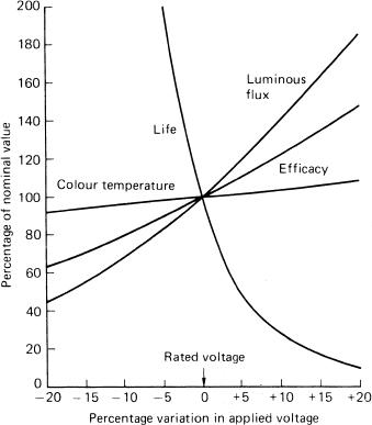
Figure 3.9Variations in the characteristics of a tungsten lamp when voltage is altered by small amounts
An advantage of flashbulbs and electronic flash is the reliability of light output and quality that can be obtained. Flashbulbs in particular have an output which is dependent only on manufacturing tolerances. Electronic flash gives an acceptably constant output provided adequate recharging time is allowed between successive flashes. The ready-light indicators fitted to many units glow when only about 80 per cent of the charging voltage is reached; at this point the energy available for the flash is only some two-thirds of full charge. A further time must be allowed to elapse before discharge, to ensure full capacity is available.
Digital cameras used for still life photography, when either three successive colour-filtered exposures are given, or a triple linear photosensor array is scanned across the format with a short time exposure, require that the light output of the source is dependably constant to prevent the appearance of colour banding in the image. Sources such as HMI lamps and high intensity fluorescent sources are found to be suitable for this demanding task.
Efficiency
The efficiency of a light source for photographic use is related to factors determining its usefulness and economy in particular circumstances. These include control circuitry utilizing design techniques to give a low power consumption and choice of reflector to concentrate light output in a particular direction. Electronic flash units are examples of efficient reflector design, with little of the luminous output wasted.
The photographic effectiveness of a light source relative to a reference source is called its actinity, and takes into account the SPD of the source and the spectral response of the sensitized material or photosensor array. Obviously it is inefficient to use a source poor in ultraviolet radiation with materials whose sensitization is predominantly in the blue and ultraviolet spectral regions. A measure of the efficiency of a light source is efficacy. This is the ratio of luminous flux emitted to the power consumed by the source and is expressed in lumens per watt. A theoretically perfect light source emitting white light of daylight quality would have an efficacy of about 220 lumens per watt. Values obtained in practice for some common light sources are given in Table 3.2 above. The obsolete term ‘half-watt’ was formerly applied to general-purpose filament lamps, which were presumed to have an efficacy of 1 candle-power per half-watt, corresponding roughly to 25 lumens per watt. This value was optimistic.
Reliability is one of the most desirable attributes of a photographic light source. Incandescent sources often fail when switched on, due to power surges and physical changes in the filament. Power control devices such as dimmers and series-parallel switching arrangements can reduce such occurrences. Extensive switching operations and vibration in use should be avoided. Electronic flash units may be very reliable in operation but cannot be repaired by the user. Because of the high voltages and currents involved, electronic flash apparatus should always be treated with respect. Most flash units have some form of automatic ‘dump’ circuit to dispose of redundant charge when output is altered or the unit switched off. Modern lighting units of compact dimensions, light weight, ease of portability and incorporating devices such as automatic control of output as in electronic flashguns, certainly ease the task of operation, but the disposition of the lighting arrangements on the subject for effect is still a matter of skill on the part of the user.
Some maintenance is necessary for every light source, varying with the particular unit. It may be as simple as ensuring reflectors are cleaned regularly or batteries are replaced or recharged as recommended. The ability of a light source to operate on a variety of alternative power sources such as batteries, mains or a portable generator may be a decisive factor in its choice. Other convenience factors relate to the comfort of the operator and subject, such as the amount of heat generated and the intensity of the light. Undoubtedly, electronic flash lighting is superior in these aspects.
Daylight
A great deal of photographic work is done out of doors in ordinary daylight. Daylight typically includes direct light from the sun, and scattered light from the sky and from clouds. It has a continuous spectrum, although it may not be represented exactly by any single colour temperature. However, in the visible region (though not outside it) colour temperature does give a close approximation of its quality. The quality of daylight varies through the day. Its colour temperature is low at dawn, in the region of 2000 K if the sun is unobscured. It then rises to a maximum, and remains fairly constant through the middle of the day, to tail off slowly through the afternoon and finally fall rapidly at sunset to a value which is again below that of a tungsten-filament lamp. The quality of daylight also varies from place to place according to whether the sun is shining in a clear sky or is obscured by cloud. The reddening of daylight at sunrise and at sunset is due to the absorption and scattering of sunlight by the atmosphere. These are greatest when the sun is low, because the path of the light through the earth’s atmosphere is then longest. As the degree of scattering is more marked at short wavelengths, the unscattered light which is transmitted contains a preponderance of longer wavelengths, and appears reddish, while the scattered light (skylight) becomes more blue towards sunrise and sunset.
These fluctuations prohibit the use of ordinary daylight for sensitometric evaluation of photographic materials. Light sources of fixed colour quality are essential. For many photographic purposes, especially in sensitometry, the average quality of sunlight is used as the standard (skylight is excluded). This is referred to as mean noon sunlight, and approximates to light at a colour temperature of 5400 K. Mean noon sunlight was obtained by averaging readings taken in Washington by the (then) US National Bureau of Standards at the summer and winter solstices of 21 June and 21 December in 1926. Light of similar quality, but with a colour temperature of 5500 K, is sometimes referred to as ‘photographic daylight’. It is achieved in the laboratory by operating a tungsten lamp under controlled conditions so that it emits light of the required colour temperature, by modifying its output with a Davis–Gibson liquid filter. Sunlight SPD is of importance in sensitometry, not so much because it may approximately represent a standard white, but because it represents, perhaps better than any other single energy distribution, the average conditions under which the great majority of camera photographic materials are exposed.
Near noon, the combination of light from the sun, sky and clouds usually has a colour temperature in the region of 6000 to 6500 K. An overcast (cloudy) sky has a somewhat higher colour temperature, while that of a blue sky may become as high as 12 000 to 18 000 K. The colour temperature of the light from the sky and the clouds is of interest independently to that of sunlight, because it is skylight alone which illuminates shadows and gives them a colour balance that differs from that of a sunlit area.
Tungsten-Filament Lamps
In an incandescent photographic lamp, light is produced by the heating action of electric current through a filament of tungsten metal, with melting point of 3650 K. The envelope is filled with a mixture of argon and nitrogen gas and can operate at temperatures up to 3200 K. A further increase, to 3400 K gives increased efficacy but a decrease in lamp life. ‘Photoflood’ lamps are deliberately overrun at the latter temperature, to give a high light output, at the expense of a short life.
A tungsten-filament lamp is designed to operate at a specific voltage, and its performance is affected by deviation from this condition, as by fluctuations in supply voltage. Figure 3.9 shows how the characteristics of a filament lamp are affected by changes to normal voltage: for example, a 1 per cent excess voltage causes a 4 per cent increase in luminous flux, a 2 per cent increase in efficacy, a 12 per cent decrease in life and a 10 K increase in colour temperature for a lamp operating in the range 3200–3400 K.
Tungsten lamps are manufactured with a variety of different types of cap, designated by recognized abbreviations such as BC (bayonet cap), ES (Edison screw) and SCC (small centre contact). Certain types of lamp are designed to operate in one position only. Reference to manufacturers’ catalogues will furnish details as to burning position as well as cap types and wattages available.
There are various photographic tungsten lamps in use:
- General service lamps are the type used for normal domestic purposes and available in sizes from 15 W to 200 W with clear, pearl or opal envelopes. The colour temperature of the larger lamps ranges from about 2760 K to 2960 K, with a life of about 1000 hours.
- Photographic lamps are a series of lamps made specially for photographic use, usually as reflector spotlights and floodlights. The colour temperature is nominally 3200 K, which is obtained at the expense of a life of approximately 100 hours only. The usual power rating is 500 W. Such lamps have been superseded by more efficient, smaller tungsten–halogen lamps with greater output and longer life.
- Photoflood lamps produce higher luminous output and more actinic light by operating at 3400 K; they have an efficacy of about 2.5 times that of general service lamps of the same wattage. Two ratings are available. The smaller No. 1 type is rated at 275 W, with a life of 2–3 hours. The larger No. 2 type is rated at 500 W, with a life of 6–20 hours. Photoflood lamps are also available with internal silvering in a shaped bulb, and these do not need to be used with an external reflector.
- Projector lamps are available in a variety of types, with wide variations in cap design, filament shape, and size. They may include reflectors and lenses within the envelope. Operation is at mains voltage or reduced voltage by step-down transformer. Wattages from 50 to 1000 are available. Colour temperature is in the region of 3200 K and lamp life is given as 25, 50 or 100 hours. Once again, the compact size of the tungsten–halogen lamp has great advantages in such applications; and operation at low voltages such as 12 or 24 V allows use of a particularly robust filament. Many colour enlargers use projector lamps as their light source.
Tungsten–Halogen Lamps
The tungsten–halogen lamp is a type of tungsten lamp with a quantity of a halogen added to the filling gas. During operation a regenerative cycle is set up whereby evaporated tungsten combines with the halogen in the cooler region of the vicinity of the envelope wall, and when returned by convection currents to the much hotter filament region the compound decomposes, returning tungsten to the filament and freeing the halogen for further reaction. There are various consequences of this cycle. Evaporated tungsten is prevented from depositing on the bulb wall which thus remains free from blackening through age. Filament life is also considerably extended owing to the returned tungsten, but eventually the filament breaks as the redeposition is not uniform. The complex tungsten–halogen cycle functions only when the temperature of the envelope exceeds 250°C, achieved by using a small-diameter envelope of borosilicate glass or quartz (silica). The increased mechanical strength of such a construction permits the gas filling to be used at several atmospheres pressure. This pressure inhibits the evaporation of tungsten from the filament and helps increase the life of such lamps as compared with that of conventional tungsten lamps of equivalent rating. The small size of tungsten–halogen lamps has resulted in lighter, more efficient luminaires and lighting units as well as improved performance from projection optics.
Early lamps of this type used iodine as the halogen and the lamps were commonly known as ‘quartz-iodine’ lamps. Other halogens and their derivatives are now used. Tungsten–halogen lamps are available as small bulbs and in tubular form, supplied in a range of sizes from 50 to 5000 W with colour temperatures ranging from 2700 to 3400 K. Special designs can replace conventional 500 W tungsten lamps in spotlights and other luminaires with the added advantage of some 200 hours life and near-constant colour temperature. Replacement costs are higher, however. Most tungsten–halogen lamps operate at low voltages (12 or 24 V), which means that a much more compact filament can be used than with conventional filament lamps.
Fluorescent Lamps
A fluorescent lamp is a low-pressure mercury-vapour discharge lamp with a cylindrical envelope coated internally with a mixture of fluorescent materials or phosphors. These absorb and convert short-wave UV radiation into visible light, the colour of which depends on the mixture of phosphors used. The resultant light quality can be made a close visual match to continuous-spectrum lighting.
Fluorescent lamps emit a line spectrum with a strong continuous background; their light quality can be expressed approximately as a correlated colour temperature. The colour rendering index may also be quoted. There are many subjective descriptive names for fluorescent lamps, such as ‘daylight’, ‘warm white’ and ‘natural’, but there is little agreement between manufacturers as to the precise SPD of a named variety. Lamps are also classified into two main groups, ‘high-efficiency’ and ‘de-luxe’. The former group have approximately twice the light output of the latter for a given wattage, but are deficient in red. They include ‘daylight’ lamps of approximately 4000 K and ‘warm white’ lamps of approximately 3000 K, a rough match to domestic tungsten lighting. The de-luxe group gives good colour rendering by virtue of the use of lanthanide (rare-earth element) phosphors, and includes colour matching types at equivalent colour temperatures of 3000, 4000, 5000 and 6000 K.
Colour images recorded using fluorescent lamps, even if only present as background lighting, may result in unpleasant green or blue colour casts, especially on colour reversal film, needing corrective filtration by means of suitable colour-compensating filters over the camera lens.
Fluorescent lamps are supplied in the form of tubes of various lengths for use in a variety of domestic and industrial fittings. Domestic lamps operate at mains voltage and use a hot cathode, to maintain the discharge, which is usually initiated by a switch starter which produces a pulse of high voltage sufficient to ionize the gas. Cold-cathode fluorescent lamps use an emissive cathode at much higher voltages, and have instant-start characteristics. Such lamps, in grid or spiral form, were once used in large-format enlargers. However, such light sources are unsuitable for colour printing purposes. The life of a fluorescent tube is usually of the order of 7000 to 8000 hours, and the output is insensitive to small voltage fluctuations.
Metal-Halide Lamps
Originally the only metals used in discharge lamps were mercury and sodium, as the vapour pressures of other metals tend to be too low to give adequate working pressure. However the halides of most metals have higher vapour pressures than the metals themselves. In particular the halides of lanthanide elements readily dissociate into metals and halides within the arc of a discharge tube. The ionized metal vapour emits light with a multi-line spectrum and a strong continuous background, giving what is virtually a continuous spectrum. The metals and halides recombine in cooler parts of the envelope. Compounds used include mixtures of the iodides of sodium, thallium and gallium, and halides of dysprosium, thulium and holmium in trace amounts. The discharge lamp is a very small ellipsoidal quartz envelope with tungsten electrodes and molybdenum seals. Oxidation of these seals limits lamp life to about 200 hours, but by enclosing the tube in an outer casing and reflector with an inert gas filling, life can be increased to 1000 hours.
The small size of this lamp has given rise to the term compact-source iodide lamp (CSI). Light output is very high, with an efficacy of 85 to 100 lumens per watt. A short warm-up time is needed. The hydragyrum metal iodide (HMI) lamp uses mercury and argon gases with iodides of dysprosium, thulium and holmium to give a daylight-matching spectrum of precisely 5600 K and CRI of 90 with a high UV output also.
When these sources are operated on an AC supply the light output fluctuates at twice the supply frequency. Whereas the resulting variation in intensity is about 7 per cent for conventional tungsten lamps it is some 60–80 per cent for metal halide lamps. This can cause problems when used for short exposure durations in photography, unless a three phase supply or special ballast control gear is used. Ratings of up to 5 kW are available.
Pulsed Xenon Lamps
Pulsed xenon lamps are a continuously operating form of electronic flash device. By suitable circuit design a quartz tube filled with xenon gas at low pressure discharges at twice the mains frequency, i.e. 100 Hz for a 50 Hz supply, so that although pulsed, the light output appears continuous to the eye. The spectral emission is virtually continuous, with a colour temperature of approximately 5600 K (plus significant amounts of ultraviolet and infrared radiation). Forced cooling may be needed. The physical dimensions of such lamps are small, and they have replaced traditional carbon-arc lamps and especially used for film projection. Power ratings up to 8 kW are available, and lamp life is 300 to 1000 hours depending on type.
Expendable Flashbulbs
The traditional flashbulb is now obsolescent with only a very few types available. They still have specific uses however, such as for lighting very large interiors or for high speed recording where a series of bulbs fired in a ‘ripple’ give an intense compact source for a short time. Electronic flash units are now very compact in size and have replaced the traditional flashgun for expendable photochemical flashbulbs. However it is useful to document the properties and features of flashbulbs.
Flashbulbs contain fine metal ribbon in an atmosphere of oxygen at low pressure, enclosed in a glass envelope with a lacquer coating to prevent shattering when fired. The metal ribbon in smaller bulbs was hafnium or zirconium; larger bulbs use an aluminium–magnesium alloy. On ignition by the passage of electric current through a filament, a bright flash of light is emitted as the metal burns, of duration about 0.01 to 0.02 seconds, the larger bulbs emitting a longer flash. The emission spectrum is continuous, with a CT of about 3800 K. A transparent blue lacquer coating converts this CT to 5500 K. Blue flashbulbs were originally intended for use with colour film, but they are equally suitable for black-and-white materials. In the case of flashbulb arrays such as ‘flash-cubes’, four small clear flashbulbs were each housed with their individual reflectors in an outer enclosure of transparent blue plastic material which acted as a colour conversion filter.
Flashbulbs are triggered from batteries with a voltage range from about 3 to 30 volts. Although a circuit which connects a 3 V or 4.5 V DC voltage directly across the bulb will fire the bulb, for greater reliability a battery-capacitor circuit is used (Figure 3.10). A battery charges a capacitor through a high resistance. The discharge of the capacitor then fires the bulb. A small 15 V or 22.5 V battery is commonly used in such a circuit; these cannot be used on their own to fire the flashbulb because of their high internal resistance. In the circuit shown in Figure 3.10 the capacitor is charged only when a bulb is inserted into a socket, so that battery life is conserved if the flashgun is stored without a bulb in place. The resistor is of a value sufficiently high to ensure that the capacitor-charging current will not fire the flashbulb, but is low enough to give a short charging time. A test lamp is used to check on the state of charge. Such a circuit may be used to fire several flashbulbs simultaneously in a multiple-flash set-up. The limitations to this arrangement are the resistances of the connecting wires, which may be quite long. A better arrangement is to use slave units connected to the individual extension flashguns so one flashbulb is triggered from the camera shutter contacts, and the light emitted by it operates photocell switches installed in the slave units to give near-simultaneous firing.
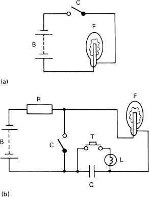
Figure 3.10Flashbulb firing circuits. (a) Direct ignition from battery B (3–45 volts DC) to flashbulb F using shutter synchronization or ‘open flash’ contacts C. (b) Capacitor ignition where B is 15 or 22.5 volts, resistor R is 3–5 kilohms and capacitor C is 100–250 microfarads. Pushbutton switch T is for charge test lamp L
To avoid the necessity for batteries, alternative methods were used for firing flashcubes and other arrays of bulbs in units intended primarily for simple cameras. The ‘Magicube’ type used mechanical firing of a special bulb containing a tube loaded with a priming chemical. Each bulb had its own external torsion spring. On releasing the shutter the primer tube was struck by the spring. The primer ignited and fired the filling. The time from firing to peak output intensity was a usefully short 7 milliseconds.
Alternatively, a piezo-electric crystal in the camera body produced the firing pulse when struck by a striker mechanism coupled to the camera shutter release. Bulbs in a spatial array were fired sequentially by current-steering thermal switches which in turn closed circuit paths to the next bulb. Both of these arrangements required cameras with the firing arrangements included in their construction.
Flashbulb performance is shown as a graph of emitted luminous flux plotted against time, as in Figure 3.11, and various parameters can be determined. Effective flash duration is a measure of the motion-stopping power of the flash and is the time interval between half-peak points. The camera shutter must be fully open at the point of peak output. The total light output (in lumen seconds) is given by the area under the curve.

Figure 3.11Flashbulb characteristics. The characteristics are shown on a graph of light output in lumens against time in milliseconds for a Magicube A and a Flip-Flash B. The time to half-peak is X, time to peak is Y and effective flash duration is Z, measured between half-peaks. For bulb A, X, Y and Z have values of 4, 7 and 9.5 ms respectively. For bulb B, X, Y and Z have values of 7, 13 and 14.5 ms respectively
A guide number or flash factor can be used to calculate camera exposure. A guide number (G) is the product of the f-number (N) of the camera lens and the subject distance (d) in metres for film of speed 100 ISO.
![]()
Guide numbers are quoted for a range of film speeds and exposure times for leaf shutters. They are subject to modification to suit the particular conditions of use, being influenced by the reflective properties of the surroundings of the subject. Guide numbers are estimated from the following formula:
![]()
where L is the maximum light flux in lumens, t is the exposure duration in seconds, R is the reflector factor and S is the arithmetic film speed. A modification necessary for units with built-in reflectors such as flashcubes, is to
![]()
where E is the effective beam intensity of the bulb. This quantity is measured by an integrating light meter across the entire angle of coverage of the reflector and is not influenced by hot spots. It replaces the alternative beam candle power (BCP), which was measured at the centre of the beam only, and could be misleading.
The problems of flash synchronization with the shutter are discussed in Chapter 9.
Electronic Flash
Flash Circuitry
In an electronic flashtube, an electrical discharge takes place in an atmosphere of a gas such as xenon, krypton or argon or a mixture of these gases, causing emission of a brief, intense flash of light. Unlike the contents of expendable flashbulbs, the active components are not consumed by this operation and the tube may be flashed repeatedly, with a life expectancy of many thousands of flashes.
The essentials of an electronic flash circuit are shown in Figure 3.12. A capacitor is charged from a solid-state high-voltage DC supply of the order of 350 to 500 V, through a current-limiting resistor. This resistor allows a high-power output from a low-current-rated supply with suitably long charging times, of the order of several seconds; also, because the charge current is limited the gas becomes deionized and the flash is extinguished after the discharge. At the charging voltage the high internal resistance of the gas in the flashtube prevents any flow of current from the main capacitor; but by apply a triggering voltage (typically a short pulse of 5–15 kV) by means of an external electrode, the gas is ionized and becomes conducting, allowing the capacitor to discharge rapidly through it, resulting in a brief flash of light. This voltage is a spark coil arrangement using a capacitor and transformer, and is usually triggered by the shutter contacts in the camera. The voltage is limited to less than 150 V and 500 µA by positioning it on the low-voltage side of the spark coil, so that this voltage appears only on the contacts, preventing possible accidental injury to the user and damage to the shutter contacts. The trigger electrode may be in the form of fine wire around the flashtube or a transparent conductive coating.
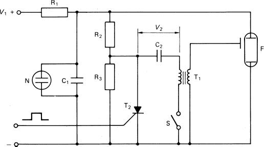
Figure 3.12Basic electrical circuit for an electronic flashgun. The input voltage V1 charges the main capacitor C1 via limiting resistor R1. The neon light N shows the state of charge reached. The trigger capacitor C2 is charged by a primary trigger voltage V2. R2 and R3 are limiting resistors. Closure of shutter contacts S and receipt of a pulse by the triggering thyristor T2 causes C2 to discharge through primary of trigger transformer T1 to give a high voltage pulse to the external electrode of the flashtube F. The tube becomes conducting and C1 discharges through it to produce a brief flash of light
The SPD of the flash discharge is basically the line spectrum characteristic of xenon, superimposed on a very strong continuous background. The light emitted has a correlated colour temperature of about 6000 K. The characteristic bluish cast given by electronic flash with some colour reversal materials may be corrected either by a light-balancing filter with a low positive mired shift value, or by a pale yellow colour-compensating filter. Often the flashtube or reflector is tinted yellow or yellow-green as a means of compensation. The flashtube may be of borosilicate glass or quartz, the former giving a cut-off at 300 nm, the latter at 180 nm. Both transmit wavelengths up to 1500 nm in the infrared region. By suitable design of control circuitry, ultraviolet or infrared output can be enhanced, so an electronic flashgun can be a useful source of these radiations as well as visible light.
Flash Output and Power
The power output is altered by switching additional capacitors in or out of circuit, or the current may be divided between two tubes or separate heads or by thyristor control. The output can be ‘symmetrical’ or ‘asymmetrical’, e.g. 1000 Ws–1 divided either into 2 × 500 or 4 × 250, or into 500 plus 2 × 250 Ws–1 respectively. Alternative low-power settings typically offer alternative outputs from 1/2 to 1/32 of full power in halving steps. Extension heads may be used for multiple flash arrangements and each head may have its own capacitor. If the extension head shares the main capacitor output the connecting lead must be substantial, to reduce resistance losses. For greatest efficiency the connection between capacitor and flashtube must be as short and of as low resistance as possible. One-piece or ‘monobloc’ studio flash units are examples of this type. The use of slave units for synchronization facilitates multiple-head flash operation.
The energy input Ei per flash in watt-seconds (Ws–1), often still called ‘joules’ (J), not all of which is available as output, is given by
![]()
where C is the capacitance in microfarads and V is the voltage in kilovolts. The energy output Eo is estimated by a formula for flash energy conversion such as
![]()
where K1 is the conversion efficiency (some 50–60 per cent), K2 is the percentage of spectral bandwidth used, K3 is the percentage of the emitted light directed at the subject by the optical system, and K4 is an empirical factor.
Small integral units are rated at 5–20 Ws–1 (joules), hand-held units for on-camera at 20–200 Ws–1, while large studio flash units are available with ratings of some 200–5000 Ws–1. The state of charge of the capacitor, i.e. readiness for discharge, is indicated by a neon light or beeping sound circuit which is usually set to strike at about 80 per cent of maximum voltage, i.e. at about two-thirds full charge. Several seconds must be allowed to elapse after this to ensure full charge. If the flash is not then triggered, various forms of monitoring circuitry may be used to switch the charging circuitry on and off to maintain full charge (‘top-up’) with minimum use of the power supply while conserving battery power. Some units may be equipped with monitoring circuitry that switches it off if not used within a set period. The stored energy is ‘dumped’ as a safety measure.
Changes to the flash circuitry allow the flash tube to be operated in a strobe mode, i.e emit a series of short flashes as well as a longer single flash. This allows a series of ‘preflashes’ to be emitted for redeye reduction or for scene analysis, or during the shutter operation to give a multiple exposure strobe effect or to allow high shutter speeds to be used.
Flash Duration and Exposure
The characteristics of an electronic flash discharge are shown in Figure 3.13. The effective flash duration (t) is usually measured between one-third-peak power points, and the area under the curve between these points represents approximately 90 per cent of the light emitted, measured in lumen-seconds or effective beam-candela-seconds. The flash duration t, as defined above, in a circuit whose total tube and circuit resistance is R with a capacitor of capacitance C is given approximately by

Figure 3.13Characteristics of electronic flash. (a) Conventional graph of light output in megalumens against time in milliseconds. (b) Comparison of electronic flash and a medium size flashbulb. (c) Variation of effective flash duration, curves 1 to 4, as the discharge is quenched for automatic exposure by a thyristor circuit
![]()
So, for a 1 millisecond duration flash, the requirements are for high capacitance, low voltage and a tube of high internal resistance. The flash duration is usually in the range 2 ms to 0.02 ms to effect a compromise between ability to stop motion and avoidance of the possible effects of high-intensity reciprocity law failure. Units may have a variable output, controlled either by switching in or out of additional capacitors or by automatic ‘quenching’ controlled by monitoring of scene or image luminance (see later), giving a suitable variation in either intensity or flash duration. For example, a studio flash unit on full power may have a flash duration of 2 ms, changing to 1 ms and 0.5 ms when half- and quarter-power respectively are selected. Some special microflash units for scientific applications may have outputs whose duration is of the order of 1 microsecond but with only about 1 Ws–1 of energy. The output efficacy (P) of a flashtube is defined as being

where L is the peak output (in lumens). The guide number of a flash unit with reflector factor R used with a film of arithmetic speed rating S is given by
![]()
A useful practical point is that for a given flash unit the flash guide number for distance in metres for ISO 100 film is usually incorporated in the designation number of the unit, e.g. 45 means G = 45.
The usual practical restrictions apply to guide number values. The silvered reflectors used with electronic flashguns are highly efficient and direct the emitted light into a well-defined rectangular area with sharp cut-off, approximating to the coverage of a semi-wide-angle lens on a camera. Coverage may be altered to greater or lesser areas to correspond with the coverage of other lenses or a zoom lens by the addition of clip-on diffusers or by moving a Fresnel type condenser lens in front of the flashtube to an alternative position. A moving tube ‘zoom’ feature may even be controlled automatically by the camera itself as a zoom lens is operated.
The use of diffusers and ‘bounce’ or indirect flash severely reduces the illumination on the subject and often needs corrective filtration with colour materials owing to the nature and colour of the reflective surface. This can be used to advantage, as when a golden-surfaced umbrella reflector is used to modify the slight blue cast given by some flash units, which may have colour temperatures of 6000 K or more. The main result of ‘bounce’ lighting is to produce softer, more even illumination. An umbrella-type reflector of roughly paraboloidal shape, made of translucent or opaque material, with white or metallic silver or gold finish, is a widely used accessory item, as are translucent umbrellas and ‘soft boxes’ to diffuse the light.
Portable Units
A portable flash unit is small enough to be carried conveniently and attached to a camera without strain on the hotshoe connection (see Figure 3.14a), although a side bracket may be preferred (see Figure 3.14b). The power supply is normally batteries. There are various alternatives and occasionally a mains adapter may be available. The simplest is a high-voltage dry battery, but this is heavy and expensive.

Figure 3.14Attachment of flash units to a camera. (a) Using a hotshoe on the pentaprism housing. The flash unit has dual tubes for a mixture of direct and bounce flash. (b) Using a side bracket. The box connected to the hotshoe contains circuitry to interface the flashgun with the camera to provide a range of automatic features
The preferred alternative is a low-voltage battery giving 6–9 V with suitable circuitry to convert this into high voltage. This can be a transistorized oscillator to convert DC into AC (producing a characteristic whining noise); the voltage is increased by a step-up transformer and then rectified to DC once more.
Batteries may be of the zinc–carbon variety, or alkaline–manganese for improved performance. Alternatively, rechargeable nickel–cadmium (NiCd) or lead–acid cells may be used. A set of NiCd batteries may have a capacity only enough for about 40 full-power flashes (enough for a 36 exposure film) in the absence of energy-saving circuitry (see later). Circuitry may be incorporated inside the flash unit for the recharging cycle using mains power. A visual state-of-charge indicator in the forms of floating coloured balls has been used with lead–acid cells, as the relative density of the acid varies with the level of discharge. NiCd batteries are completely sealed and need no maintenance other than an occasional full discharge to prevent loss of capacity due to a ‘memory’ effect if they are frequently recharged before being fully exhausted. This memory effect does not occur with other types such as nickel metal hydride and lithium ion batteries. An LED display may show the state of charge or discharge of a set of batteries, very convenient in use. Where size and weight is crucial, small but powerful lithium batteries can be used, but these are usually single-use types only.
A range of accessories is available. The reflectors may be interchangeable from ‘bare-bulb’ to a deep paraboloid to give different beam shapes and lighting effects. Various modes of use include direct flash at full power, tilting reflectors for bounce flash, fractional output for close-up work or fill-in flash in sunlight, automatic exposure mode, programmed mode or stroboscopic mode. A data display panel using liquid crystal technology gives a comprehensive readout of the operational mode in use.
Studio Flash
A studio flash unit is of substantial size and weight (Figure 3.15) and usually used indoors but is transportable. Output is from 250 to 5000 Ws–1. The power supply is from the mains (a special supply may be needed) or a generator for location work, or even a large battery pack. The discharge tube may be in a linear or helical shape or possibly circular to give a ‘ring-flash’. Studio units have the convenience of a ‘modelling lamp’ positioned near the discharge tube to give a preview of the proposed lighting effect. The modelling lamp may be a photoflood or tungsten– halogen lamp, often with fan-assisted cooling, and its output may be variable, with the flash output selected so as to facilitate visual judgement of lighting balance. The flash output of a studio unit may be selected manually by switches or by remote control (Figure 3.16), or by a cordless infrared programming unit used in the hand from the camera position. The flash output may be set within limits as precisely as one-tenth of a stop, a great convenience in balancing lighting rather than by shifting lights about, and allowing a smaller studio to be used.

Figure 3.15A two-head studio flash unit with stands, generator and case for transportation. The deep parabolic reflector units are interchangeable for other types
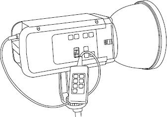
Figure 3.16A studio flash head with remote control of output via a handset. A display on the unit shows the status of the unit
The calculation of the appropriate lens aperture setting may be arrived at by using guide numbers, practical experience, exposure meter readings using modelling light illumination, or usually by the use of an integrating flash meter. Automatic methods include the use of photocells to monitor the scene luminance or the image luminance on the film surface by reflected light to a photocell in the camera body during the flash discharge. This is termed off-the-film (OTF) flash metering. As a confirmation and to give confidence in the outcome, a sheet of Polaroid self-developing film may be exposed to evaluate exposure and lighting, as well as to check that everything is operating satisfactorily.
Automatic Flash Exposure
A significant development in flashgun design was the automation of camera exposure determination and consequent power-saving advantages. This feature uses solid-state rapid acting devices called thyristor switches.
A rapid-acting photosensor such as a phototransistor or silicon photodiode (SPD) monitors the subject luminance when being illuminated by the flash discharge, and the resultant output signal integrated until it reaches a preset level. The flash discharge can then be abruptly cut off to give the correct exposure, subject to some limitations. The switch-off level is determined by the film speed and lens aperture in use. Typically, the integrating circuit is a capacitor which charges up to a preset voltage level, the time taken being a function of the intensity and duration of light reaching the photocell (Figure 3.17).

Figure 3.17The operation of automatic electronic flash units. (a) Charging characteristics of the integrating capacitor shown as voltage against time. Voltage V1 is the preset triggering level. (b) Arrangement of the quench tube and thyristor switch. (c) Preferred power-saving arrangement. Key: C main capacitor, F flashtube, S subject, P photocell, T thyristor switch, Q quench tube, N neutral density wedge, A integrating amplifier preset to give a pulse to the thyristor at voltage V1 of the charging curve of the timing capacitor as shown in (a). t1, t2 and t3 are various flash durations determined by the operating conditions
The discharge is switched off by the thyristor. There are two possibilities. First, the discharging capacitor may have its residual energy diverted into an alternative ‘quench’ tube, which is a low-resistance discharge tube connected in parallel with the main tube. The quench circuit is activated only when the main tube has ignited so as to prevent effects from other flashguns in use in the vicinity. There is no light output from the quench tube and the dumped energy is lost. The effective flash duration, dependent on subject distance, reflectance and film speed, may be as short as 0.02 ms, with concomitant motion-stopping ability.
The second, preferred switching arrangement saves the residual charge in the capacitor and thereby reduces recharging time per successive flash and also increases the total number of flashes available from a set of batteries. This energy-saving circuitry has the thyristor switch positioned between the main capacitor and the flashtube. The characteristic of the thyristor is that it may be closed on command, i.e. when the flash is initiated, and then opened almost instantaneously on receiving a pulse from the light-monitoring circuit to terminate the flow of current sustaining the flash. Obviously a high current-handling ability is needed. An added advantage is that full flash discharge is possible in manual mode simply by taking the monitoring photocell out of circuit or covering it over so that the ‘open’ pulse is never given. To allow for the use of different film speeds and lens apertures the photocell may be biased electrically or mechanically. The former method would cause alterations in the firing voltage of the timing capacitor, so the latter is usually preferred and is also much easier, requiring only a vane-type mask or a turret of neutral-density filters over the photocell. The two types of circuit arrangement are shown in Figure 3.17. The circuitry also allows for a choice of maximum outputs to suit a range of subject distances with a selected f-number, so that overexposure does not occur say with close-up photography, or that there can be some control of depth of field. The flash duration reduces as the flash is quenched more rapidly over a range of usually 30 or 50 to 1, i.e. from 1 ms at full power to 0.02 ms at minimum power. This is useful for capturing motion of a subject. Flash colour temperature may also change with output duration, tending to rise as duration reduces.
The photocell can be in a small hotshoe-mounted housing attached to the flash unit by a flying lead (Figure 3.18), which allows monitoring of scene luminance irrespective of the flash-head position, and, in particular, allows for the use of bounce flash. It is desirable with flashguns having an integral photocell that this is positioned to face the subject irrespective of the direction in which a rotatable or swivelling flashtube assembly may be pointed. Often a second supplementary flashtube is integrated into the gun, giving a small direct flash towards the subject to offset some of the less desirable effects of the bounce lighting from the main tube (Figure 3.19). Two or more automatic flashguns can be combined for multiple flash work using suitable connecting leads. The hotshoe connection on the camera provides a single central ‘X’ flash synchronization connection. Depending on the camera system, several other connections may be provided to interface the flashgun with the camera to provide features such as automatic selection of a shutter speed for correct synchronization when the flash is attached, a ‘thunderbolt’ readylight indication in the viewfinder, use of a short ‘preflash’ for autofocus use or exposure determination and control of a zoom flash feature. The flash synchronization may be selectable to be first blind or second blind type where it is triggered either by the first blind uncovering the film gate or by the second blind just before it starts to cover up the gate. This latter feature is useful for combined flash and short time exposures with moving subjects to give an enhanced impression of motion. The problems of flash synchronization to the camera shutter are dealt with in Chapter 9.

Figure 3.18A small flash unit connected to the hotshoe by an extension lead terminating in a small housing containing the photocell for automatic operation

Figure 3.19Front, side and rear views of a small automatic flashgun. The combined Fresnel lens and diffuser shapes the output beam. A secondary flashtube gives direct flash. The flash head can be tilted and swivelled for indirect flash. A simple display on the back shows operating range
The flash unit may be controlled by a photocell located inside the camera which monitors the luminance of the image of the scene actually on the film surface while the camera shutter is fully open at the flash synchronization speed when the film gate is fully uncovered. The photocell used may be a segmented type to provide a weighted analysis of the tonal range and distribution in the scene, often referred to as ‘matrix flash’. In particular, for use in ambient light to provide fill-in by ‘synchro-sunlight’ techniques, this scene analysis can provide exactly the right amount of supplementary flash to give a more pleasing image. A typical block diagram for dedicated-flash operation is shown in Figure 3.20.
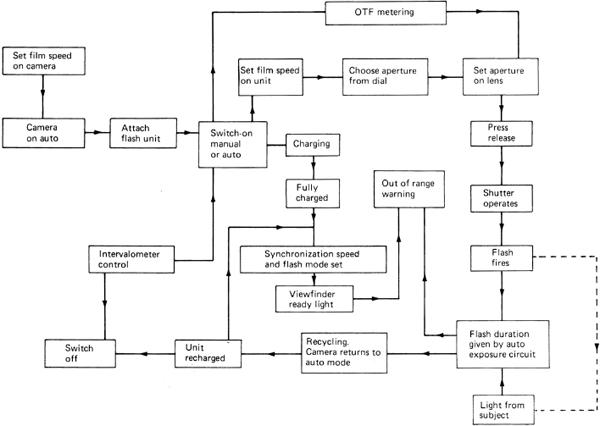
Figure 3.20Flow diagram of dedicated flashgun operation. The major stages of operational sequences and the features offered by such flashguns are shown
An automatic flashgun may only operate fully with a particular camera, when it is called a ‘dedicated’ flashgun. Independent manufacturers supply interchangeable modules to allow a flashgun to be used fully with different cameras.
Integral Flash Units
As flash units have decreased in size but still retain a useful output, more cameras are provided with an inbuilt or integral flash unit. This can be just a fixed output flash arrangement as in the case of single-use cameras or a more sophisticated system with a range of modes in other cameras. In compact cameras the flash is automatically activated when the light level is too low for an ambient-light exposure. The flash output may be just a single full discharge, the necessary lens aperture being set to the required value according to the guide number for the unit by using subject distance information from the autofocus system used in the camera. This has been referred to as a ‘flashmatic’ system. In more complex cameras, particularly the SLR type, the flashgun is often fully automated with a photocell for through-the-lens and off-the-film operation. The user may be able to select from a menu of modes such as ‘automatic’, i.e selected according to subject luminance, ‘off’ when no flash fires, ‘on’ when the flash fires irrespective of light conditions and always at full power, or ‘red-eye reduction’ to alleviate this disturbing effect.
Redeye Avoidance
An unfortunate optical consequence of an integral flash is that the flashtube is located rather too close to the lens so that the light is directed essentially along the optical axis. This direct axial lighting can be a problem with reflective subjects when a glare spot is given in the picture, but even more so when a subject is looking at the camera. Light enters the eye via the pupil, which is usually fully dilated in the dim light conditions requiring the use of flash, and illuminates the retina at the back of the eye which is rich in red blood vessels. The result is a characteristic bright red pupil instead of the expected black. This red-eye effect can be reduced or removed in various ways. The ambient light can be increased to cause the pupil to contract, or a small projector in the camera or flashgun can direct a pencil beam of light at the face to same effect or the flashgun can emit a number of short preflashes before the main exposure, when hopefully the pupil will have reacted. Other methods require the sitter to look away from the camera lens, but the most effective method is to move the flashtube as far away from the camera lens as possible. This influences camera design and the integral flash unit may be on a short extension of the camera body for use. The same problems occur with portable flash units and they should not be used attached to the camera if possible but on an extension cable. The choice and disposition of lighting to suit the ‘treatment’ of the subject is beyond the scope of this book.
The various forms of flash synchronization and output, whether full, quenched and pulsed, are shown and compared in Figure 3.21.

Figure 3.21Flash modes and shutter synchronization. (a) First and second blind synchronization: 1, first (leading) blind; 2, second (trailing) blind; A, shutter triggered; B, reflex mirror time; C, blind travel time; D, flash triggered by first blind (X synchronization); E, flash triggered by second blind; O, film gate fully uncovered (flash synchronization speed); L, flash output; T, elapsed time; t, flash duration (nominal); K, main flash; Q, start of blind travel. (b) Quenched electronic flash: t2, reduced flash duration; L2 reduced flash output. (c) Red-eye reduction by bright preflashes: f1, f2, f3, preflashes. (d) Matrix metering of scene using faint preflashes: f1 to fn, weak preflashes; J, data processing. (e) Flash with high shutter speeds, e.g. to 1/12 000 second, using high frequency strobe flashes: P, pulsed strobe flash. (f) Flash synchronization errors: M, incorrect use of M instead of X synchronization setting; W, shutter speed too short for synchronization, a travelling slit is formed
Other Sources
A number of other light and radiation sources find use in photography and digital imaging, for both image capture and illumination systems.
Light Emitting Diodes
The light emitting diode or LED is a very small solid-state device encapsulated in a housing with integral lens to direct and shape the emitted beam. Operation is by electroluminescence using forward biasing of a p–n junction in materials such as gallium arsenide or gallium phosphide. Light output is monochromatic and, typically, red (649 nm), green (570 nm) or infrared (850 nm). The LED can be mains or battery powered and has very modest power consumption, but can still be a significant drain on the limited capacity of the battery in a camera. It has a principal use as an indicator light for equipment operational conditions or modes. The small source can be used alone or behind a patterned mask to give an alphanumerical or symbolic display, as in a view-finder or flashgun data readout. The usual states are off, on, pulsing or dimmed (given by altering a flashing rate from a pulsed supply).
To provide a more intense beam suitable for illumination purposes, LEDs are used in arrays of multiple sources, e.g. emitting in the near infrared as used for covert work to illuminate a scene for recording by a suitable infrared system. An illuminator operating from a 12 V supply can illuminate a scene up to 25 m distant. Illuminators can be rectangular, linear or annular in shape to suit the illumination task. A pulse rate up to 150 Hz is typical. The red monochromatic emission finds use also in the darkroom as a bright safelight for room illumination or as a portable unit for hand-held local illumination.
Diode Lasers
The diode laser or ‘microlaser’ is a semiconductor crystal derived from gallium arsenide that emits intense coherent light at a few wavelengths by stimulated emission, as compared to the spontaneous emission of an LED that produces incoherent light with a wider spectral range. The astigmatic shape of the output beam requires optical correction to a circular form. The devices can be assembled in rectangular array, linear (bar) or single source form. Laser wavelengths of 750 to 780 nm are typically used in optical disc (compact disc CD) reader systems with a single source. Wavelengths of 670 and 780 nm are suited to printing plate technology using digital data direct from computer image files.
These devices can have an intense monochromatic output suited to three-colour (red, green, blue) exposure systems in various forms of printer to provide a hard copy output from digital files and may even use three different infrared wavelengths to expose the three colour-forming image layers. Display systems may use red (656 nm), green (532 nm) and blue (457 nm) modulated microlaser beams to form a direct write display.
Bibliography
Carlson, V. and Carlson, S. (1991) Professional Lighting Handbook, 2nd edn. Focal Press, Boston, MA.
Cayless, M. and Marsden, A. (eds) (1983) Lamps and Lighting, 3rd edn. Edward Arnold, London.
Edgerton, E. (1970) Electronic Flash, Strobe. McGraw-Hill, New York.
Fitt, B. and Thornley, J. (1997) Lighting Technology. Focal Press, Oxford.
Minnaert, M. (1993) Light and Colour in the Outdoors. Springer-Verlag, New York.
Ray, S. (1994) Applied Photographic Optics, 2nd edn. Focal Press, Oxford.
Ray, S. (1999) Scientific Photography and Applied Imaging. Focal Press, Oxford.