
5The Photometry of Image Formation
The light-transmitting ability of a photographic lens, which principally determines the illuminance of the image at the film plane, is usually referred to as the speed of the lens. Together with the effective emulsion ‘speed’ or photosensor sensitivity and the subject luminance, this determines the exposure duration necessary to give a correctly exposed result. The separate problem of the determination of camera exposure is dealt with in Chapter 19. In the sections below the factors influencing image illuminance are examined in detail.
Stops and Pupils
An optical system such as a camera and lens normally has two ‘stops’ located within its configuration. The term stop originates from its original construction of a hole in an opaque plate perpendicular to the optical axis. One of these two is the field stop, which is the film gate or photosensor array; this determines the extent of the image in the focal plane and also the field of view of the lens.
The aperture stop is usually located within the lens or close to it, and controls the transmission of light by the lens. It also influences depth of field (Chapter 4) and lens performance, in terms of the accuracy of drawing and resolution in the image.
In a simple lens the aperture stop may either be fixed, or only have one or two alternative settings. A compound lens is usually fitted with a variable-aperture stop called an iris diaphragm because of its similar function to the iris in the human eye. The iris diaphragm is continuously adjustable between its maximum and minimum aperture sizes. The usual construction is five or more movable blades, providing a more or less circular opening. The aperture control ring may have click settings at whole and intermediate f-number values. In photography the maximum aperture as well as the aperture range is important, as aperture value is one of the primary creative controls in picture making.
In a compound lens with an iris diaphragm located within its elements, the apparent diameter of the iris diaphragm when viewed from the object point is called the entrance pupil (EN). Similarly, the apparent diameter of the iris diaphragm when viewed from the image point is called the exit pupil (EX) (Figure 5.1). These two are virtual images of the iris diaphragm, and their diameter is seldom equal to its actual diameter. To indicate this difference the term pupil factor or pupil magnification (p) is used; this is defined as the ratio of the diameter of the exit pupil to that of the entrance pupil (p = EX/EN). Symmetrical lenses have a pupil factor of approximately one, but telephoto and retrofocus lenses have values that are respectively less than and greater than unity. Pupil magnification influences image illuminance, as shown below. Note that the pupils are not usually coincident with the principal planes of a lens, indeed the exit pupil can be at infinity.

Figure 5.1Location of the stops and pupils of a triplet lens and the passage of light through the system. O, object; I, image; A, aperture stop (iris diaphragm); F, field stop (film gate and format size); C, principal ray; M, marginal ray; EN, entrance pupil; EX, exit pupil
Aperture
The light-transmitting ability of a lens, usually referred to as aperture (due to the control exercised by the iris diaphragm) is defined and quantified in various ways. Lenses are usually fitted with iris diaphragms calibrated in units of relative aperture. This is represented by a number N, which is defined as the equivalent focal length f of the lens divided by the diameter d of the entrance pupil (N = f/d). This diameter is sometimes referred to incorrectly as the effective aperture of the lens in contrast to the actual aperture of the lens, which is the mean diameter of the actual aperture formed by the diaphragm opening (this is not necessarily circular). The term effective aperture properly refers to the relative aperture value when corrected for a lens that is not focused on infinity.
Relative aperture is N = f/d (for infinity focus) so a lens with an entrance pupil 25 mm in diameter and a focal length of 50 mm has a relative aperture of 50/25, i.e. 2. The numerical value of relative aperture is usually prefixed by the italic letter f and an oblique stroke, e.g. f/2, which serves as a reminder of its derivation. The denominator of the expression used alone is usually referred to as the f-number of the lens. Aperture value on many lenses appears as a simple ratio, so the aperture of an f/2 lens is shown as ‘1:2’.
The relative aperture of a lens is commonly referred to simply as its ‘aperture’ or even as the ‘f-stop’. The maximum aperture is the relative aperture corresponding to the largest diaphragm opening that can be used with it. For simple lenses the lens diameter (D) itself, or the stop diameter close to the lens, is substituted for the entrance pupil: thus the f-number of a simple lens is its focal length divided by its diameter (N = f/D).
To simplify exposure calculations, f-numbers are usually selected from a standard series of numbers, each of which is related to the next in the series by a constant factor calculated so that the amount of light passed by the lens when set to one number is half that passed by the lens when set to the previous number, as the iris diaphragm is progressively closed. As the amount of light passed by a lens is inversely proportional to the square of the f-number, the numbers in the series increase by a factor of ![]() , i.e. 1.4 (to 2 figures). The standard series of f-numbers is f/1, 1.4, 2, 2.8, 4, 5.6, 8, 11, 16, 22, 32, 45, 64. Smaller or larger values are seldom encountered.
, i.e. 1.4 (to 2 figures). The standard series of f-numbers is f/1, 1.4, 2, 2.8, 4, 5.6, 8, 11, 16, 22, 32, 45, 64. Smaller or larger values are seldom encountered.
The maximum available aperture of a lens may, and frequently does, lie between two of the standard f-numbers above, and in this case will be marked with a number not in the standard series.
A variety of other series of numbers have been used in the past, using a similar ratio, but with different starting points. Such figures may be encountered on older lenses and exposure meters. In the case of automatic exposure in cameras offering shutter priority and program modes, the user may have no idea whatsoever of the aperture setting of the camera lens. An alteration in relative aperture corresponding to a change in exposure by a factor of 2 either larger or smaller is referred to as a change of ‘one stop’. Additional exposure by alteration of ‘one-third of a stop’, ‘half a stop’ and ‘two stops’ refer to exposure factors of 1.26, 1.4 and 4 respectively. When the lens opening is made smaller, i.e. the f-number is made numerically larger, the operation is referred to as ‘stopping down’. The converse is called ‘opening up’.
The exposure control choices of either changing shutter speeds or alteration of the effective exposure index of a film (by adjusted processing) are often also referred to by their action on effective exposure in terms of ‘stops’, e.g. a ‘one-stop push’ in processing to double the film speed value.
Mechanical Vignetting
The aperture of a lens is defined in terms of a distant axial object point. However, lenses are used to produce images of extended subjects, so that a point on an object may be well away from the optical axis of the lens, depending on the field of view. If the diameter of a pencil of rays is considered from an off-axis point passing through a lens, a certain amount of obstruction may occur because of the type and design of the lens, its axial length and position of the aperture stop, and the mechanical construction of the lens barrel (Figure 5.2). The effect is to reduce the diameter of the pencil of rays that can pass unobstructed through the lens and hence the amount of light reaching the focal plane. This is termed mechanical vignetting or ‘cut-off’, and the image plane receives progressively less light as the field angle increases. This causes darkening at the edges of images and is one factor determining image illuminance as a function of field angle and hence the circle of illumination. Mechanical vignetting must not be confused with the natural fall-off of light due to the geometry of image formation (see later). Vignetting may be reduced by designing lenses with oversize front and rear elements, and by careful engineering of the lens barrel. The use of an unsuitable lens hood or two filters in tandem, especially with a wide-angle lens, also cause cut-off and increases peripheral darkening.

Figure 5.2Cause of mechanical vignetting. (a) With a short lens barrel, the area of cross-section of the oblique beam is only a little less than that of the axial beam. (b) With a long barrel, the area of the cross-section of the oblique beam is much smaller than that of the axial beam
Image Illumination
A camera lens projects an image formed as the base of a cone of light whose apex is at the centre of the exit pupil (centre of projection). It is possible to deduce from first principles an expression for the illumination or illuminance at any point in the image of a distant, extended object. To do this however, it is necessary to make use of two relationships (the derivations of which are beyond the scope of this book), concerning the light flux reflected or emitted by a surface and the luminance (brightness) of the aerial image given by the lens.
Luminous Flux Emitted by a Surface
In Figure 5.3, the flux F emitted by a small area S of a uniformly diffusing surface (i.e. one that appears equally bright in all directions) of luminance L into a cone of semi-angle ω is given by the equation
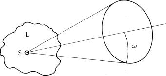
Figure 5.3The light flux F emitted by a small area S of a surface of luminance L into a cone of semi-angle ω is given by ![]()
![]()
Note that the flux emitted is independent of the distance of the source. This equation is used to calculate the light flux entering a lens.
Luminance of an Image Formed by a Lens
The transmission of a lens is measured by transmittance (T), the ratio of emergent flux to incident flux. For an object and an image that are both uniformly diffuse, and whose luminances are L and L respectively, it may be shown using equation (1) that for an ‘ideal’ lens of transmittance T
![]()
In other words, the image luminance of an aerial image is the same as the object luminance apart from a small reduction factor due to the transmittance of the lens, within the cone of semi-angle ω. Viewing the aerial image directly gives a bright image, but this cannot easily be used for focusing, except by passive focusing devices or no-parallax methods. Instead the image has to be formed on a diffuse surface such as a ground glass screen and viewed by scattering of the light. The processes of illumination also cause this image to be much less bright than the direct aerial image.
Image Illuminance
The projected image formed at the photoplane suffers light losses from various causes, so the illumination or illuminance is reduced accordingly. Consider the case shown in Figure 5.4, where a thin lens of diameter d, cross-sectional area A and transmittance T is forming an image S at a distance v from the lens, of a small area S of an extended subject at a distance u from the lens. The subject luminance is L and the small area S is displaced from the optical axis such that a principal ray (i.e. one through the centre of the lens) from object to image is inclined at angle θ to the axis. The solid angle subtended by the lens at S is ω. The apparent area of the lens seen from S is A cos θ The distance between the lens and S is u/cos θ.

Figure 5.4The factors determining image illuminance
The solid angle of a cone is defined as its base area divided by the square of its height. Consequently,

The flux leaving S at the normal is LS, so the flux leaving S at an angle θ into the cone subtended by the lens is LS cos θ. Thus the flux K entering the lens is given by:
![]()
Hence from equation (2), the flux K′ leaving the lens is given by
![]()
Now, illumination is defined as flux per unit area, so image illuminance E is
![]()
From geometry, by the ratio of the solid angles involved,
![]()
Hence
![]()
An evaluation of the variables in equation (3) gives a number of useful results and an insight into the factors influencing image illuminance and exposure.
The value of E is independent of u, the subject distance, although the value of v is related to u by the lens equation.
The axial value of illuminance is given when θ = 0, then cos θ = 1 and cos4 θ = 1. Hence
![]()
Now lens area A is given by
![]()
![]()
For the subject at infinity, v = f. By definition, the relative aperture N is given by N = f/d. By substitution into equation (5) we thus have:
![]()
Equation 6 gives us the important result that, for a distant subject, on the optical axis in the focal plane, E is inversely proportional to N2. Hence image illuminance is inversely proportional to the square of the f-number. For two different f-numbers N1 and N2, the ratio of corresponding image illuminances is given by
![]()
Thus, for example, it is possible to calculate that the image illuminance at f/4 is one-quarter of the value at f/2.
The exposure H received by a film during exposure duration t is given by
![]()
Consequently, for a fixed exposure time, as H is proportional to E, then from equation
![]()
Also, from equation (8), E is inversely proportional to t, so E1/E2 = t2/t1, hence the exposure time t1 and t2 required to produce equal exposures at f-numbers N1 and N2 respectively are given by
![]()
Also, from equation (7), E is inversely proportional to N2. In other words, image illuminance is proportional to the square of the lens diameter, or effective diameter of the entrance pupil. Thus by doubling the value of d, image illuminance is increased fourfold. Values may be calculated from
![]()
To give a doubling series of stop numbers, the value of d is altered by a factor of ![]() giving the standard f-number series.
giving the standard f-number series.
An interesting result also follows from equation (6). By suitable choice of photometric units, such as by taking E in lux (lumen/m2) and L in apostilbs (l/π cd/m2), we have
![]()
So for a lens with perfect transmittance, i.e. T = 1, the maximum value of the relative aperture N is f/0.5, so that E = L. (Values close to f/0.5 have been achieved in special lens designs.)
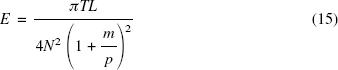
When the object distance u is not large, i.e. closeup photography or photomacrography, we cannot take v = f in equation (5), but instead use v = f(1 + m) from the lens equation. Consequently
![]()
The relative aperture N = f/d, so
![]()
Alternatively, the effective aperture N′ = N(1+m), so
![]()
Usually it is preferable to work in terms of relative aperture as an f-number (N) which is marked on the aperture control of the lens, and magnification (m) which is often known or set, so equation (13) is preferred to equation (14). In addition, for photo-macrography, when non-symmetrical lenses, and particularly retrofocus lenses may be chosen used in reverse mode, the pupil factor p = EX/EN must be taken into account for the effective aperture. The relationship is that N = N (1 + m/p) and is due to the non-correspondence of the principal planes from which u and v are measured and the pupil positions from which the image photometry is derived. Substituting into equation (14),
For most subjects not in the close-up region, equation (6) is sufficient.
When we consider image illumination off-axis, θ is not equal to 0. Then cos4 θ has a value less than unity, rapidly tending to zero as θ approaches 90 degrees. In addition, we have to introduce a vignetting factor (V) into the equation to allow for vignetting effects by the lens with increase in field angle. So our equation for image illuminance, allowing for all factors, is now:

From equation (16) we see that E is proportional to cos4 θ. This is the embodiment of the so-called cos4 θ law of illumination, or ‘natural vignetting’ as it is sometimes called, which may be derived from the geometry of the imaging system, the inverse square law of illumination and Lambert’s cosine law of illumination. The effects of this law are shown in Figure 5.5 (ignoring the effects of ‘mechanical’ vignetting). It can be seen that even a standard lens with a semi-angle of view of 26 degrees has a level of image illuminance at the edge of the image of only two-thirds of the axial value. For a wide-angle lens with a semi-angle of view of 60 degrees, peripheral illuminance is reduced to 0.06 of its axial value. For wide-angle lens designs, corrective measures are necessary to obtain more uniform illumination over the image area.
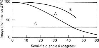
Figure 5.5The effect of the cos4 θ law of illumination. (A) Natural light losses due to the law. (B) Improvements possible by utilizing Slussarev effects. (C) Use of a graduated neutral-density ‘anti-vignetting’ or ‘spot’ filter
Image Illuminance with Wide-Angle Lenses
There are several possible methods of achieving more uniform illumination in the image plane; these are related to the design of a lens and its particular applications.
Mechanical Methods
An early method of reducing illumination fall-off was a revolving star-shaped device in front of the lens, used on the unique Goerz Hypergon lens, which at f/16 had an angle of field of 120 degrees. A more modern remedy is a graduated neutral density filter or spot filter, in which density decreases non-linearly from a maximum value at the optical centre to near-zero at the periphery; this can provide a fairly precise match for illumination fall-off. Such filters are widely used with wide-angle lenses of symmetrical configuration. There is a penalty in the form of a +2 EV exposure correction factor. Oversize front and rear elements are also used to minimize mechanical vignetting.
Negative Outer Elements
As shown, a major cause of illumination fall-off is that the projected area of the aperture stop is smaller for rays that pass through it at an angle. This angle can be reduced if the lens is designed so that its outermost elements are negative and of large diameter. Lens designs such as quasi-symmetrical lenses with short back foci, and also retrofocus lenses, both benefit from this technique. The overall effect is to reduce the ‘cos4 θ effect’ to roughly cos3 θ.
The Slussarev Effect
Named after its discoverer, this approach uses the deliberate introduction of the aberration known as coma into the pencils of rays at the entrance and exit pupils of the lens. Their cross-sectional areas are thereby increased, so that illuminance is increased at the periphery, but the positive and negative coma effects cancel out and have little adverse effect on image quality.
Uncorrected Distortion
Finally, the theoretical consideration of image illuminance applies only to well-corrected lenses that are free from distortion. If distortion correction (which becomes increasingly difficult to achieve as angle of field increases) is abandoned, and the lens design deliberately retains barrel distortion so that the light flux is distributed over proportionally smaller areas towards the periphery, then fairly uniform illuminance is possible even up to the angles of view of 180 degrees or more. ‘Fish-eye’ lenses are examples of the application of this principle. The relationship between the distance y of an image point from the optical axis changes from the usual y = f tan θ of an orthoscopic lens to y = f θ (θ in radians) for this type of imagery.
Exposure Compensation for Close-Up Photography
The definition of relative aperture (N) assumes that the object is at infinity, so that the image conjugate v can be taken as equal to the focal length f. When the object is closer this assumption no longer applies, and instead of f in the equation N = f/d, we need to use v, the lens extension. Then N is defined as equal to v/d where N is the effective f-number or effective aperture.
Camera exposure compensation may be necessary when the object is within about ten focal lengths from the lens. Various methods are possible, using the values of f and v (if known), or magnification m, if this can be measured. Mathematically, it is easier to use a known magnification in the determination of the correction factor for either the effective f-number N or the corrected exposure duration t′. The required relationships are, respectively:
![]()
or
![]()
and
![]()
i.e.
![]()
These expressions are readily derived from the lens equation and equation (10). The exposure correction factor increases rapidly as magnification increases. For example, at unit magnification the exposure factor is × 4 (i.e. +2 EV), so that the original estimated exposure time must be multiplied by four or the lens aperture opened up by two whole stops.
For copying, where allowance for bellows extension must always be made, it may be more convenient to calculate correction factors based on an exposure time that gives correct exposure at unit magnification. Table 5.1 gives a list of exposure factors.
Table 5.1 Exposure correction factors for different scales of reproduction (magnification)
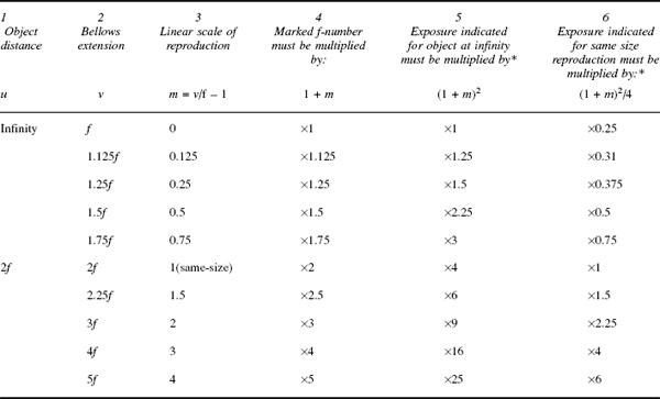
*The exposure factors in columns 5 and 6 are practical approximations.
The use of cameras with through-the-lens (TTL) metering systems is a great convenience in close-up photography, as compensation for bellows extension is automatically taken into account. TTL metering is also essential with lenses using internal focusing and for zoom lenses with variable aperture due to mechanical compensation, as the effective aperture may not vary strictly according to theory since focal length changes with alteration of focus too. Similarly, due to the pupil magnification effect, the use of telephoto and retrofocus design lenses with a reversing ring may need an exposure correction factor differing from that calculated by equations (16) and (18). The variable m must be replaced by m/p, where p is the pupil magnification. Lenses that use internal focusing where an inner group is moved axially have a change of effective focal length and hence the marked value of N for close-up work. A set of correction tables is needed or again the use of TTL metering gives automatic compensation.
Light Losses and Lens Transmission
Some of the light incident on a lens is lost by reflection at the air–glass interfaces and a little is lost by absorption. The remainder is transmitted, to form the image. So the value of transmittance T in equation (2) and subsequent equations is always less than unity. The light losses depend on the number of surfaces and composition of the glasses used. An average figure for the loss due to reflection might be 5 per cent for each air–glass interface. If k (taken as 0.95) is a typical transmittance at such an interface, then as the losses at successive interfaces are multiplied, for n interfaces with identical transmittance, the total transmittance T = kn. This means that an uncoated four-element lens with eight air– glass interfaces would have reflection losses amounting to some (0.95)8 = 35 per cent of the incident light, i.e. a transmittance of 0.65.
Flare and Its Effects
Some of the light reflected at the lens surfaces passes out of the front of the lens and causes no trouble other than loss to the system; but a proportion is re-reflected from other surfaces (Figure 5.6) and may ultimately reach the film. Some of this stray diffuse non-image-forming light is spread uniformly over the surface of the film, and is referred to as lens flare or veiling glare. Its effects are greater in the shadow areas of the image and cause a reduction in the image illuminance range (contrast). The flare light may not be spread uniformly; some may form out-of-focus images of the iris diaphragm (‘flare spots’) or of bright objects in the subject field (‘ghost images’). Such flare effects can be minimized by anti-reflection coatings, baffles inside the lens and use of an efficient lens hood. Light reflected from the inside of the camera body, e.g. from the bellows of a technical camera, and from the surface of the film or photosensor, produces what is known as ‘camera flare’. This effect can be especially noticeable in a technical camera when the field covered by the lens gives an image circle appreciably greater than the film format. Such flare can often be considerably reduced by use of an efficient lens hood.
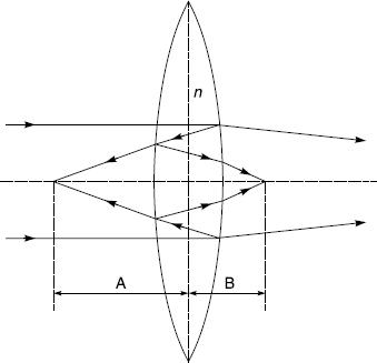
Figure 5.6Formation of flare spots by a simple lens. Images of the source are formed at distances A and B, where:
![]()
and a = 2, 4, 6 …, b = 3, 5, 7, … For n = 1.5, A = f/4, f/10, f/16 etc. and B = f/7, f/13, f/19 etc.
The number obtained by dividing the subject luminance range (SLR) by the image illuminance range (IIR) is termed the flare factor (FF), so FF = SLR/IIR. Flare factor is a somewhat indeterminate quantity, since it depends not only on the lens and camera but also on the distribution of light within and around the subject area. The value for an average lens and camera considered together may vary from about 2 to 10 for average subject matter. The usual value is from 2 to 4 depending on the age of the camera and lens design. A high flare factor is characteristic of subjects having high luminance ratio, such as back-lit subjects.
In the camera, flare affects shadow detail in a negative more than it does highlight detail; in the enlarger (i.e. in the print), flare affects highlight detail more than shadow detail. In practice, provided the negative edges are properly masked in the enlarger, flare is seldom serious. This is partly because the density range of the average negative is lower than the log-luminance range of the average subject, and partly because the negative is not surrounded by bright objects, as may happen in the subject matter. In colour photography, flare is likely to lead to a desaturation of colours, as flare light is usually a mixture approximating to white. Flare may also lead to colour casts caused by coloured objects outside the subject area.
In practice, because lens transmission is never 100 per cent, relative aperture or f-number N (as defined by the geometry of the system) does not give the light-transmitting capability of a lens. Two lenses of the same f-number may have different transmittances, and thus different speeds, depending on the type of construction, number of components, and type of lens coatings. The use of lens coatings to reduce reflection losses markedly improves transmission, and there is a need in some fields of application for a more accurate measure of the transmittance of a lens. Where such accuracy is necessary, T-numbers, which are photo-metrically determined values taking into account both imaging geometry and transmittance, may be used instead of f-numbers. The T-number of any aperture of a lens is defined as the f-number of a perfectly transmitting lens which gives the same axial image illuminance as the actual lens at this aperture. For a lens of transmittance T and a circular aperture,
![]()
Thus a T/8 lens is one which passes as much light as a theoretically perfect f/8 lens. The relative aperture of the T/8 lens may be about f/6.3. The concept of T-numbers is of chief interest in cinematography and television, and where exposure latitude is small. It is implicit in the T-number system that every lens should be individually calibrated.
Depth of field calculations still use f-numbers as the equations used have been derived from the geometry of image formation.
Anti-Reflection Coatings
Single Coatings
A very effective practical method of increasing the transmission of a lens by reducing the light losses due to surface reflection is by applying thin coatings of refractive material to the air–glass interfaces or lens surfaces. The effect of single anti-reflection coating is to increase transmittance from about 0.95 to 0.99 or more. For a lens with, say, eight such interfaces of average transmittance 0.95, the lens total transmittance increases from (0.95)8 to (0.99)8, representing an increase in transmittance from 0.65 to 0.92, or approximately one-third of a stop, for a given f-number. In the case of a zoom lens, which may have 20 such surfaces, the transmittance may be increased from 0.36 to 0.82, i.e. more than doubled. Equally important is the accompanying reduction in lens flare, giving an image of improved contrast where, without the use of such coatings, such a lens design would be of little practical use.
The effect of a surface coating depends on two principles. First, the surface reflectance R, the ratio of reflected flux to incident flux, depends on the refractive indexes n1 and n2 of the two media forming the interface; in simplified form (from Fresnel’s equations) this is given by
![]()
In the case of a lens surface, n1 is the refractive index of air and is approximately equal to 1, and n2 is the refractive index of the glass. From equation (22) it can be seen that reflectance increases rapidly with increase in the value of n2. In modern lenses, using glasses of high refractive index (typically 1.7 to 1.9), such losses would be severe without coating.
Secondly, in a thin coating there is interference between the light wavefronts reflected from the first and second surfaces of the coating. With a coating of thickness t and refractive index n3 applied to a lens surface (Figure 5.7), the interaction is between the two reflected beams R1 and R2 from the surface of the lens and from the surface of the coating respectively. The condition for R1 and R2 to interfere destructively and cancel out is given by
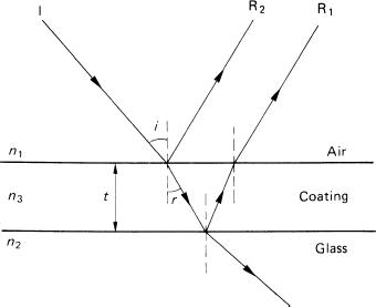
Figure 5.7An anti-reflection coating on glass using the principle of destructive interference of light between reflections R1 and R2
![]()
where r is the angle of refraction and λ the wavelength of the light. Note that the light energy lost to reflection is transmitted instead. For light at normal incidence this expression simplifies to
![]()
Equation 24 shows that to satisfy this condition the ‘optical thickness’ of the coating, which is the product of refractive index and thickness, must be λ/4, i.e. one-quarter of the wavelength of the incident light within the coating. This type of coating is termed ‘quarter-wave coating’. As the thickness of such a coating can be correct for only one wavelength it is usually optimized for the middle of the spectrum (green) and hence looks magenta (white minus green) in appearance. By applying similar coatings on other lens surfaces, but matched to other wavelengths, it is possible to balance lens transmission for the whole visible spectrum and ensure that the range of lenses available for a given camera produce similar colour renderings on colour reversal film, irrespective of their type of construction.
The optimum value of n3 for the coating is also obtained from the conditions for the two reflected wavefronts to interfere destructively and cancel. For this to happen the magnitudes of R1 and R2 need to be the same. From equation (22) we can obtain expressions for R1 and R2:
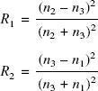
By equating R1 = R2 and taking n1 = 1, then ![]()
So the optimum refractive index of the coating should have a value corresponding to the square root of the refractive index of the glass used.
For a glass of refractive index 1.51, the coating should ideally have a value of about 1.23. In practice the material nearest to meeting the requirements is magnesium fluoride, which has a refractive index of 1.38. A quarter-wave coating of this material results in an increase in transmittance at an air–glass interface from about 0.95 to about 0.98 as the light energy involved in the destructive interference process is not lost but is transmitted.
Types of Coating
Evaporation
The original method of applying a coating to a lens surface is by placing the lens in a vacuum chamber in which is a small container of the coating material. This is electrically heated, and evaporates, being deposited on the lens surface. The deposition is continued until the coating thickness is the required value. This technique is limited to materials that will evaporate at sufficiently low temperatures.
Electron Beam Coating
An alternative technique to evaporative coating is to direct an electron beam at the coating substance in a vacuum chamber. This high-intensity beam evaporates even materials with very high melting points which are unsuitable for the evaporation technique. Typical materials used in this manner are silicon dioxide (n = 1.46) and aluminium oxide (n = 1.62). The chief merit of the materials used in electron beam coating is their extreme hardness. They are also used to protect aluminized and soft optical glass surfaces.
Multiple Coatings
Controlled surface treatment is routinely applied to a range of other optical products. With the advent of improved coating machinery and a wider range of coating materials, together with the aid of digital computers to carry out the necessary calculations, it is economically feasible to extend coating techniques by using several separate coatings on each air–glass interface. A stack of 25 or more coatings may be used to give the necessary spectral transmittance properties to interference filters, as used in colour enlargers and specialized applications such as spectroscopy and microscopy. By suitable choice of the number, order, thicknesses and refractive indexes of individual coatings the spectral transmittance of an optical component may be selectively enhanced to a value greater than 0.99 for any selected portion of the visible spectrum (Figure 5.8).

Figure 5.8The effects on surface reflection of various types of anti-reflection coatings as compared with uncoated glass (for a single lens surface at normal incidence)
The use of double and triple coatings in modern photographic lenses is now almost universal, and numbers of coatings between 7 and 11 are claimed by some manufacturers. The use of lens coatings has made available a number of advanced lens designs that would otherwise have been unusable because of flare and low transmittance.
Bibliography
Freeman, M. (1990) Optics, 10th edn. Butterworths, London.
Hecht, E. (1998) Optics, 3rd edn. Addison-Wesley, Reading, MA.
Jenkins, F. and White, H. (1981) Fundamentals of Optics, 4th edn. McGraw-Hill, London.
Kingslake, R. (1992) Optics in Photography. SPIE, Bellingham, WA.
Ray, S. (1994) Applied Photographic Optics, 2nd edn. Focal Press, Oxford