
What exactly is compositing?
Periodically, we have mentioned the word compositing in the course of this book. What does this term mean? Compositing, in its most literal sense, means taking a stack of items and making them into one item. When we discussed analog video standards, we referred to one such standard as Composite. Composite video, if you recall, is a video signal in which all the different luma and chroma electrical signals are integrated into one electrical waveform. They become one composite signal.
Compositing in Final Cut Pro and other applications involves the process of taking more than one image and integrating the various images into one image. As one Final Cut Pro editor puts it, “Compositing is everything above Video Layer 1.” As we discovered when we worked with the sequence Timeline, Final Cut Pro allows up to 99 separate video tracks. The good news is that in this manner Final Cut Pro gives you fantastic flexibility in customizing the way those separate layers work together when they are composited into the flat image you see on the video screen.
To be successful at compositing, you really have to rework the way you think about making a visual image. Compositing is the foremost of the tasks in which there is never any one right way to accomplish a goal. Part of that lies in the fact that compositing, more than any other element, requires a mental vision of the results. Your uniqueness as a human and an artist cannot help but shine through.
No two compositors generate the same results, just as no two painters use the same brushstroke. Why must you undo your prior knowledge of image making? Because sometimes, adding red to an image is more about taking away green than it is about painting with red. Final Cut Pro gives you the ability to obscure or reveal imagery using not only the various features of light, such as opacity (visible to invisible), hue (the shade of the color) and saturation (density of the color), but also the way that obscuration or revelation occurs over time, also known as keyframing.
We’ll start with an exploration of layering, track opacity, and the Composite Modes. In the course of setting up and using these effects tools, we will also learn to use Wireframe, Keyframe Interpolation, the Text Generator, Matte and Masking tools, and the Alpha Channel.
From our definition of compositing, we already know that we need more than one layer in a sequence in order to create a composite. Layers in a sequence are stacked, one on top of the other. What you see in the Canvas window is actually what lies in the sequence as seen from the top layer down. Imagine that your sequence of video layers is a messy stack of different types of paper. Some sheets cover others; some are more transparent than others, allowing you to see through them to the next layer underneath. When you edit video clips into a new layer on the sequence, you are inserting a new sheet into the stack.
Setting up a sequence for compositing layers
STEP 1
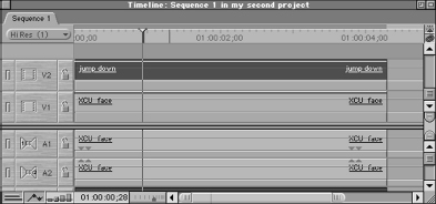
Create a new sequence in your project. Edit an initial video clip into the sequence in the Video 1 track.
STEP 2
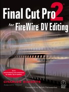
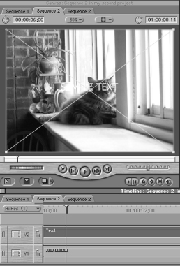
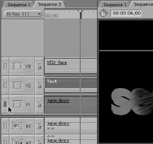
Choose another video clip, drag it to the sequence, position it in the Video 2 track, and drop it (Figure 6-1). If no Video 2 track yet exists, simply place it where the track should be, and Final Cut Pro will automatically create one.
Make sure that the sequence playhead is positioned somewhere within the clips. A glance at the Canvas window will reveal that the video clip in the Video 2 layer is covering the clip in the Video 1 layer. This is because, by default, all video clips are at 100 percent opacity. We have already explored this opacity feature in our discussion of the Clip Overlay button. When we adjusted the opacity in that chapter, there were no other video layers involved. Since the default background color for a Final Cut Pro sequence is black, changing the opacity of the clip simply resulted in a fade to black. But now that we have more than one video layer, changing the opacity of the top layer will reveal the layer below.
STEP 4
First, make sure that the Clip Overlay button is enabled in the Timeline window. Remember that the Clip Overlay button, though a part of the Timeline window, is actually a function of sequences within the Timeline window. Just because it is enabled within one sequence does not mean that it is enabled in others. If you do not see the rubberband line going through the clips in a sequence, rubberbanding is not enabled.
STEP 5
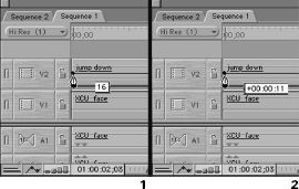
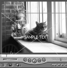
Choose the General Selection tool on the Toolbar (shortcut Command-A) and adjust the rubberband line of the clip in Video 2 layer (Figure 6-2). As you pull the line down, the red render bar will appear as expected, but looking at the Canvas window will reveal that the clip in the Video 1 layer is beginning to appear through the Video 2 layer. If you drag the line all the way down to zero, layer 2 will be transparent, totally revealing the clip beneath it.
If we render the clip, playing back will reveal that the entire clip carries the opacity level we set the rubberband line at. But how useful could this be in everyday life? Setting a static, unchanging opacity level in a clip might be useful in some situations, but in most, we need to be able to control the level of opacity over time within the clip. To do so, we need to introduce the concept of keyframing.
Keyframing in the sequence timeline
Keyframes come into use with almost all visual effects in Final Cut Pro, as well as other popular editing and compositing applications. Keyframing means that for a certain feature in a clip, such as opacity, a certain value exists at a certain time. For instance we could set a keyframe at the tenth frame of the clip for an opacity value of 25 percent. Any other frame of the same clip could have the same or a different percentage value of opacity. On any frame where we establish a specific, definite value, we create a keyframe.
In the digital universe, everything has a value. The example we are working with, opacity, has a value at any given time of between 0 to 100 percent. At 0 percent, the clip is transparent; at 50 percent, it is half-transparent; and at 100 percent, the clip is opaque. No keyframes are necessary for a clip to have an initial value; all clips do. But establishing a keyframe and giving a specific frame a value gives us the ability to change a value in a single clip over time.
If we assign the first keyframe for a feature in a clip, the value of the feature for the duration of the clip still does not change. Even though we have a keyframe, the value of this initial keyframe doesn’t change to a new value. The lesson is that one keyframe in a clip expresses only one value. To express a change in values in a clip, you must have two or more keyframes, each of which has a different value. We set a keyframe for the value we want the feature to have initially, say 100 percent opacity, then we set additional keyframes for the change in values we wish to see over the duration of the clip, say 50 percent, then 25 percent, and then 0 percent. If we do not want a value to change over time, there is no reason to insert a keyframe at all.
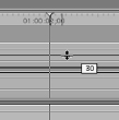
To insert keyframes into a clip’s opacity in a sequence, we need to have two features enabled. First, we need Clip Overlay to be enabled, since this is where our sequence keyframes will be inserted. Next, we need to go to the Toolbar and enable one of the last two toolsets, the Pen tool. If you click on the Pen tool and hold the mouse button briefly, you will see three options: the Pen tool, the Pen Delete tool, and the Smooth Pen tool (Figure 6-3). We will discuss the Smooth Pen tool subsequently, but for now we are concerned with the Pen and Pen Delete tools.
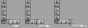
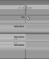
Select the Pen tool and return to the sequence. Look to the clip in the Video 2 track that you adjusted the opacity of previously. Move the mouse pointer to the beginning of the clip and place it near the rubberband line (Figure 6-4).
You may want to go into your Preferences and change Thumbnail Display from Name plus Thumbnail to Name. This will remove the thumbnail from the clip in the sequence, making it easier for you to work with the rubberband line at the beginning of a clip.
When you move to the beginning of the clip, the mouse pointer will change from the familiar arrow into the shape of the Pen tool. This indicates that the Pen tool is able to assign a keyframe for the frame you are presently hovering over.
STEP 7
Click on that rubberband line, hold the mouse button down and drag the keyframe up and down. As you do, the value box appears next to the mouse pointer informing you of the current value of the keyframe you have just created by clicking on the rubberband line.
STEP 8
Now, without releasing the keyframe, drag it from left to right and back. A timecode value box appears instead, informing you how far you have moved the keyframe from its original clicked position.
As long as you have the keyframe under the thumb of your mouse button, you have total control of the value it represents, the time it occurs within the clip, and the sequence the clip is included in. If you let go of the mouse pointer, but you want to change the keyframe’s value or position, simply grab it and drag again. After you have established a keyframe, the Pen tool displays as a crosshair when suspended over it.
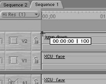
Drag the keyframe all the way to the left, so that it occurs on the first frame of the clip. Then before releasing it, drag it all the way up to the top of the clip, so that its value is 100 percent (Figure 6-5).
Now we have one keyframe. But as we mentioned earlier, one keyframe is really no different from having none. To establish a change in value, we need to add a second keyframe that occurs either before or after the initial keyframe. Since our first keyframe is at the beginning of the clip, we will move up several seconds to add the second one.
![]()
STEP 10
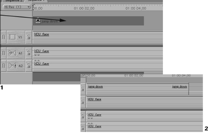
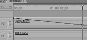
Send the sequence playhead back to the first frame by hitting the Home key on your keyboard. With the Timeline window active, type in “+300” which will move the playhead up 3 seconds from its present position (Figure 6-6). Move the Pen tool up to the sequence playhead, and watch for the Pen tool to bulls-eye the yellow triangle above the playhead indicator. When it does, click and drag the newly created keyframe down until it hits 0 percent (Figure 6-7).
Now you will have two keyframes, each of which contains a different value. The first keyframe is at the beginning of the clip at 100 percent, and the second is three seconds later at 0 percent. More interesting than this is the fact that between the two keyframes is a long slanting line denoting the change in value of opacity for all the frames in between the two keyframes. This is referred to as interpolation.
Interpolation is a process by which the computer comes up with all the values between two known values, saving you a lot of calculation. If you know that the opacity value for the clip at the first frame was 100 percent and at the end of three seconds it was zero, you’d have to do some quick math to figure what percentage of change occurred during each frame of video in between the first and the last. You could do it, but like most people, you probably hate long division and fractions, and frankly, setting all those intermediary frames wouldn’t be worth it (except for rotoscoping animation artists).
Luckily, we are dealing with a computer here, a machine designed to crunch numbers. We give Final Cut Pro the values we want the clip to have at the beginning and end keyframes in the clip, and it figures out the values for each frame in between in less time than it would take you to remember where you left your calculator. If you move the playhead back through the area of the clip that is between the two keyframes, you will see that the Video 2 layer clip slowly and evenly goes transparent as the opacity keyframe values go from 100 percent to 0 percent over 3 seconds. Each frame between the two keyframes is displayed with a progressively smaller percentage of opacity. And all you need to have for this is the two opacity keyframes that change.
Composite modes
The next sort of layer compositing we need to look at involves the way in which the various luma and chroma values of the images on a layer interact with the values of those on the layer or layers underneath. This topic is one of the most poorly understood features of Final Cut Pro and image editing applications in general. But Composite Modes should not be avoided because they provide a tool of incredible flexibility when generating layer effects.
Part of the confusion about using the Composite Modes is in understanding what they do and what needs to be in place in order for them to show results. The first requirement is obviously that the clip must be in the sequence. Since a Composite Mode is an effect that relies on a clip’s relationship with other clips, changing its Composite Mode outside of a sequence will not display its true appearance. Although you can change a clip’s Mode when it is loaded in the Viewer by itself, you won’t see the ultimate effects until it is layered above the intended clip in the sequence.
Next, Composite Modes applied to a clip always interact with the clip or clips on the layer directly beneath it. This means that when you choose a Composite Mode for a clip, you need to make sure that there is a clip underneath it that will change the clip in the way you want. If no clip exists underneath the clip whose Composite Mode you change, there may be no apparent change in the clip. Because the background of a sequence or a clip is always either Black or White or Checkerboard, based on how you have it set, you may not see much change. Composite Modes alter a clip by using the variations, or lack thereof, of the underlying clip to influence the appearance of the clip the Composite Mode has been applied to. Thus using straight Black or White backgrounds for a clip’s Composite Mode complement could yield unpredictable results or no change at all.
When you first engage a clip, its Composite Mode is set by default to Normal.
STEP 11
Clear off your sequence from the preceding example and add two stacked clips, one into the Video 1 track and one into the Video 2 track. Single click the clip in the Video 2 track to select it (Figure 6-8).
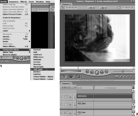
STEP 12
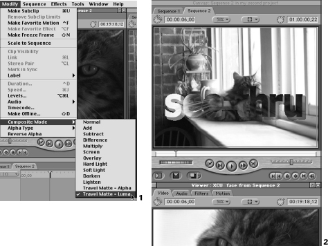
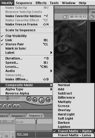
Go to the Modify drop-down menu and scan to the bottom to find Composite Modes. When you move to this submenu, you will find a list of many different Composite Modes (Figure 6-9). Each name describes how the luma and chroma values of the underlying clip will influence the appearance of the clip you apply the Mode to.
The problem for most users is that the names of the Modes do not accurately describe what the effect on your clip will be. Unlike Effects filters such as Gaussian Blur and Fish-Eye, which give some indication of their effect, the Composite Modes only describe the method by which Final Cut Pro will take the luma and chroma values of the underlying clip and use them to alter the appearance of the clip you apply the Mode to. This means that the effect resulting from the application of a Composite Mode depends on the contents of both clips and the Composite Mode chosen.
That said, there are some Modes that come into frequent use. Perhaps you want to lighten or reverse the colors in one area of your clip. You may want to enhance the effect of an Effects Filter by drawing out the luma and chroma values of a clip before applying the Filter. Some people are masters at using the Composite Modes as a type of unique paint-brush,one that is able to make complex and beautiful patterns of color and light from the mixture of math and image.
The default setting for a clip’s Composite Mode is normal, which means that the clip is not influenced by the clip below it. If you select any of the Composite Modes other than Travel Matte Alpha or Travel Matte Luma, you will begin to see interesting results.
STEP 13
In the Composite Modes submenu of the Modify drop-down menu, select a Composite Mode for the selected clip in the Video 2 track. Refer back to the Canvas window and look at the effect that the Mode creates based on the clip beneath it.
Some of the Modes show an even mixture of the two images, while others show only the darker sections of the one or the lighter sections of the other. Some reverse areas of similar or different detail, yielding odd color combinations. Each Mode gives different results based on the two clips that you have juxtaposed.
Continue choosing Modes from the list for the selected clip, noting how each Mode yields both different and sometimes similar results, depending on the two clips and the Mode.
Feel free to change the Composite Mode for a clip as often as you’d like. Of course, any clip that has its Mode changed will require rendering, because the video to be played will have changed. To turn off the Composite Mode for a clip, you must return the Composite Mode to Normal. Composite Modes are not keyframeable.
Almost alone among Final Cut Pro’s features, Composite Modes have no keyboard shortcuts or palettes, and are only available from either the Composite Modes submenu in the Modify drop-down menu or the Item Properties dialog box in the Edit drop-down menu. Hopefully, in future versions Apple will make this feature a little more accessible.
Mattes, masks, and stencils
Two of the most valuable Composite Modes were skipped in the preceding text because of their unique function and value to Final Cut Pro editors. These are Travel Matte-Alpha and Travel Matte-Luma. These tools offer the ability to frame the images of one video layer inside a shape that appears above the background layer. This is great for more advanced picture-in-picture effects, such as the ability to show one video clip through the letters of a word that uses another clip as a background.
The effect is rather like using a stencil to paint letters. If you lay the stencil on a background you want to paint the letter onto, you can paint with impunity above the stencil itself, knowing that the paint will reach only the background in the spaces that the stencil allows it to get through. Thus, three layers are involved in the process: the background, the stencil, and the layer of paint that is being used for the letters applied through the stencil.
A stencil is part of a group of tools that all perform roughly this same task. Whether they go by the name of Stencil, Mask, or Matte, these tools are part of a family referred to as mattes. Mattes allow you to obscure or reveal areas of an image based on the criteria that defines the matte. In the stencil example above, our criterion is very simple. The stencil blocks the path of the paint, restricting it to the shape of the letters the stencil is constructed to paint. Another example of a matte would be a mask that covers a light source to create shadow shapes. This tool, called a cucaloris (cookie for short) is used on a theatrical, film, video, or photography set for simulating shadows like window panes and the like.
With most real-world mattes, the intention is to block some physical element, like light beams or paint, so that a visual effect is achieved. Our mattes in the digital realm are no different, although we have more flexibility there because we are not limited to physical objects. Our mattes in the digital world can be generated by various means and can have just as many possible effects on the objects being masked.
Using the Text Generator as a matte
In order to use a Travel Matte, we need to create a matte. Our matte will be a text clip generated by Final Cut Pro’s built in Text Generator. We will put the text clip onto a Video layer between the background clip and the foreground clip. This text layer will perform as a stencil, only allowing us to see the parts of the foreground clip that occur in areas where there is text on the matte layer.
STEP 15
To make sure that your Modes are set correctly, start with a clean slate. Select and delete all clips in the sequence. Then edit what will be our background clip onto the Video 1 track. For purposes of demonstration, choose a clip with darker imagery. Once you understand the process, you can experiment with any sort of imagery you want, but a greater contrast between your clips will be better for revealing what the matte does in this process.
Next we will generate a text clip using Final Cut Pro’s built-in text generator, although you could just as easily use an image created in Photoshop or another image editing application for this purpose.
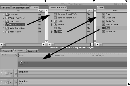
To create the text clip using Final Cut Pro, go to the Effects tab of the Browser window. Double-click and open the bin named Video Generators. Locate the bin labeled Text and double-click to open it (Figure 6-10).
STEP 17
In the Text bin that appears, grab the Text clip and drag it over to your Video 2 track in the sequence so that it covers the clip you edited into the Video 1 track. The length of the text clip will probably not match the length of your clip in the Video 1 track, but you can extend or trim edit it to whatever length you need. Trim the Text clip so that its length matches the background video clip in the Video 1 track (Figure 6-11).
Arranging and refining the clip using the wireframe and the Control tab
A glance into the Canvas window will reveal that a line of text has appeared directly in the center of the window. Since this is probably not the placement you want, we will move it using the Wireframe tools in the Canvas window. Wireframe refers to the bounding box around an object in Final Cut Pro. This bounding box does not exhibit any of the bitmap, or pixel, data of the image. It only displays the physical dimensions. It’s rather like looking at the chicken wire and structural beams of a building rather than the concrete and smoked glass windows.
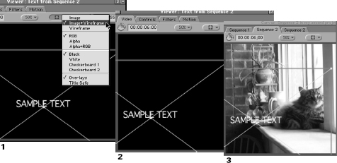
Normally, this Wireframe view is disabled, because we want to see the video we are working with, not its edges. But any direct physical adjustment we make to the image, such as its size, position, and rotation must be made using the Wireframe edges. Final Cut Pro gives us the flexibility to view our clips using either Image, which is the default view; Image+Wireframe, which shows us both; and just Wireframe, which, though uncomfortable, can be useful when the image is so complex and distracting that it makes it difficult to see and use its Wireframe edges.
STEP 18
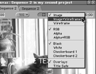
To view the Wireframes, go to the Canvas window next to the Window percent Scale menu and look for the drop-down bar that contains a small square (Figure 6-12). Click on this bar and the menu will open, revealing a long list of options. At the very top are three choices: Image, Image+Wireframe, and Wireframe. Select Image+Wireframe.
When you do so, you may or may not see a bounding box appear in the Canvas Video window. This is because Wireframes are displayed only when an object is selected.
STEP 19
Go back to the sequence Timeline, click on an empty area to deselect all clips, then single-click the text clip (Figure 6-13). A bounding box will appear in the Canvas window that covers the entire viewing area. You could also have clicked in the area of the Canvas window itself that is occupied by the clip you want to select. However, this can sometimes be difficult when dealing with text clips and other objects that are largely transparent.
STEP 20
Next, make sure that the General Selection tool is chosen in the Toolbar and go back to the Canvas window. Click on the window and drag, and you will see that the text layer moves along with the mouse pointer (Figure 6-14). The bounding box follows this movement, because you are actually moving the entire object, of which the text is only a part. Position the text in some portion of the window that feels more comfortable, such as the lower portion of the window (in the broadcast industry, titles in the lower portion of the television screen are referred to as “lower thirds”; there is another text generator in the Effects bin named Lower Thirds specifically for this purpose).
Experiment with moving the layers around using the Wireframes. Notice that you can cause the clip in the Video 1 track to contain the bounding bars by clicking it in the sequence instead. Also notice that if there are no clips selected and you click on an area in the Canvas window, one of the clips becomes selected. This is because the clip that is highest in the sequence stack of layers becomes selected once you click on any area of it in the Canvas. Notice that if both clips are selected in the sequence, both Wireframes show in the Canvas and adjustments made to one clip apply to the other. Obviously if two clips are selected simultaneously and they directly overlap each other, as our two clips would initially have done, you will only see one Wireframe. Although they are both there, one clip’s Wireframe obscures the other clip.
Notice particularly that if a layer is selected but you click on an area outside of its Wireframe, the lower clip becomes selected instead. This is a major reason that Final Cut Pro requires that Wireframes be enabled before making adjustments in the Canvas or Viewer windows: without seeing them, you could never be sure what was selected as you clicked around.
STEP 21
After you’ve played around with Wireframes briefly, make sure that the clip in the Video 1 track is lined up correctly with the frame window in the Canvas. Leave the text clip in the position you want it to occupy.
Now let’s make some adjustments to the text itself. Obviously we need to change the text in the layer, but we can also customize the size, color, font, leading, and kerning.
STEP 22
Double-click the text clip in the sequence to load it up into the Viewer window (Figure 6-15).
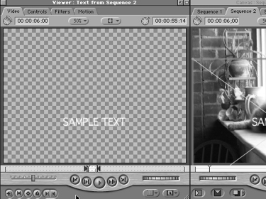
Make sure that you load the text clip by double-clicking the clip in the sequence and not the one in the Effects tab from the Browser. Changes you make to clips loaded into the Viewer directly from the Browser window do not apply to the clip in the sequence. Once you place a clip into a sequence, it becomes its own clip. Although it may have been originally generated by the Text Generator in the Effects tab, it is now a separate clip and adjustments and effects must be directly applied to it. Adjustments applied to text clips loaded into the Viewer window from the Effects tab will not have any effect on clips edited into a sequence.
When you double-click the text clip and load it into the Viewer window, the Viewer window will update, revealing a new tab and missing some that you would have expected to see. The first tab, Video, works just as it did with our captured video clips. The only difference is that here we see only our text and a checkerboard background. This is because Final Cut Pro assumes we want our text to appear as an overlay of the layer underneath. As such, it includes transparency information in the clip, a topic we will cover in detail later in the chapter.
Working with your text can be difficult if the background is distracting, so Final Cut Pro offers you the ability to change the color of the background while you work.
STEP 23
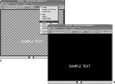
In the Viewer window, look for the same drop-down bar you adjusted the Wireframe view with earlier in the Canvas window. Click it and look for a list of background choices that read Black, White, Checkerboard 1, and Checkerboard 2 (Figure 6-16). Selecting any of these will change the background color to that selection. The correct option will depend on what color text you are working with. Since our text is currently White, select Black as the background color.
A glance at the Canvas window will reveal that this has no effect on the composite image in the sequence as displayed in the Canvas. The Background color you use in the Viewer window is just a convenience of that window, not a part of the clip itself.
STEP 24
Just for fun, return to the drop-down bar in the Viewer window and switch the Wireframe mode from Image to Image+Wireframe (Figure 6-17). You will have noticed that when you opened the text clip up in the Viewer window, the text was positioned in the same place as it is in the Canvas. This is because when we adjusted the clip’s position in the Canvas, it updated this information in the clip in the sequence. When we open up the clip from the sequence in the Viewer window, it reveals the position of the image based on the changes we made in the Canvas window.
Likewise, any changes we make to the position in the Viewer window now with the clip loaded from the sequence will be displayed in the Canvas window as the clip in the sequence is updated. This is an example of global adjustment.
With the Viewer window’s drop-down bar set to Image+Wireframe, click on the Wireframe and move it around, dropping it in yet another new location. As you will see, the Canvas is updated as the new position information ripples through the system from the Viewer to the sequence, finally to be displayed in the Canvas.
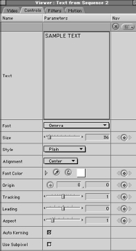
Controls, the next tab in the text clip’s Viewer window, is unique to text clips. It replaces the audio tracks that accompany most video clips. The Controls tab is where we customize the text we use in this clip.
STEP 26
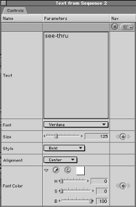
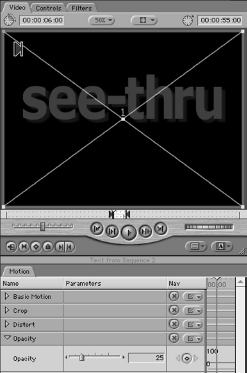
Click on the Controls tab in the Viewer window (Figure 6-18). At the top is a field to enter your text. Type in the word “see-thru” and then hit the Tab key to apply the text change. Hitting Enter would be a mistake here, since it would just result in a hard return in the text field. Either hit Tab to get out, or click the mouse pointer elsewhere in the Control tab.
The change in the text will occur immediately. To watch your text appear in the Viewer as well as the Canvas as you work in the Control tab, simply grab the Control or Video tab, tear it away from the Viewer window, and drop it in an unused area of the Desktop.
The remaining parameters in the text Control tab are standard fare for text editors. There are options for changing the font, color, size, alignment, and a host of other settings. If the list of fonts seems small, this is because Final Cut Pro can only use TrueType fonts, of which there may not be a great many on your machine. One of the great benefits of using applications such as Photoshop for creating text images is that they can usually access both Post Script and TrueType fonts for generating text images for use in Final Cut Pro, whereas our Final Cut Pro text generator is limited to the TrueType set. Many fonts are also available or can be converted to TrueType fonts, if you are limited to Final Cut Pro’s text editing capabilities.
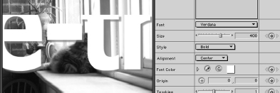
Remember that we are not creating text to be viewed as text; we are only creating a stencil for matting in a layer of video. Therefore, we need to keep in mind a couple of things. We will need a fairly large fat font, such as Verdana. If the letters of the word are too thin, there will be little video viewed through them. We also need to make the letters substantial enough to be seen at all, and the tracking—the space between the letters them-selves—will need to be kept quite tight.
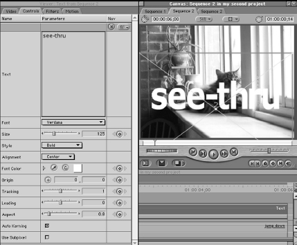
We will be able to adjust this again once our imagery is in place, but for now, set the Font as Verdana, Size at 125, Style as Bold, Alignment at Center, Color at its default White, Tracking at 1, and the Aspect at .8. Finally, reposition the text based on its new shape and size, using either the Viewer or the Canvas window Wireframes (Figure 6-19).
Setting the Travel Matte-Luma
After the text has been repositioned in an area of the screen that appeals to you, we will edit in the video clip we want to matte into the text.
STEP 28
Select a clip from the Browser window that you want to use. Make sure that you use a different clip from the one in the Video 1 track and that this clip contains footage that is generally lighter in detail.
If both clips are exactly the same or if they both contain footage that is equally bright or dark, it will be difficult to see that matting has taken place, just as if we used a stencil to paint green letters on a green wall. The text clip that we use will disappear completely, so don’t expect to see the white letters following the next operation.
STEP 29
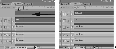
Edit the clip into a third video track, either by creating the track from the Sequence dropdown menu Insert Tracks command and then editing the clip into that target track, or by simply dragging the clip into the sequence where the third track should be and then trimming it down so that it fits your stack of clips (Figure 6-20). Either way, you should end up with a darker video clip on the Video 1 track, the text clip on the Video 2 track, and a lighter video clip in the Video 3 track. The clips should be stacked vertically so that for the moment, the video clip in the Video 3 track obscures the clips in the lower tracks.
STEP 30
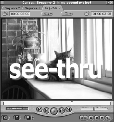
Select the clip in the Video 3 track. Go to the Modify drop-down menu, scan down to the Composite Modes, and select Travel Matte-Luma (Figure 6-21). When you do this, the Canvas window, which was previously showing only the Video 3 track, will suddenly reveal most of the Video 1 track, with the exception of the text, inside of which is video matted from your Video 3 clip.
What is occurring here is that Final Cut Pro is using the luma values of the text clip to determine what should be used as the stencil. Anything white in the text clip is stenciled and allows the Video 3 layer clip to show through onto the background clip. Anything that is black blocks the stencil and doesn’t let the Video 3 layer clip show through onto the background clip. It is performing the simple act of matting.
But unlike a normal stencil that either blocks or doesn’t block, our Travel Matte performs more like a fine-tunable screen. We can adjust how strong or weak the matte is based on how close to white an element in the clip is. White text such as we created in the Controls tab produces a complete matte, allowing the Video 3 clip to show through totally. Black, on the other hand, blocks the matte, and all we see is the background Video 1 clip.
The implication of this is that all the values in between black and white—the grays—also have luma values that are not quite here nor there. These can be used to yield mattes that are partial mattes. And since color can be keyframed within the Viewer window, you can fade your stenciled mattes in and out, just as you would with any text, but with much more pleasing results.
STEP 31
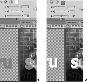
To see this difference, double-click the text clip in the sequence to load it into the Viewer again (Figure 6-22). Go to the Control tab and scroll down to the Font Color parameter. Click the little triangle to open the color selection tools.
There are sliders here for adjusting Hue, Saturation, and Brightness. Hue adjusts the actual color type, whether the color is blue, red, green, or whatever color you wish it to be. Saturation controls how intense the color is. Brightness controls the luma values, or how close to white or black the color is.
Since our Travel Matte is a luma matte, changing the Hue and/or Saturation will have only a limited ancillary effect, so we really want to adjust the Brightness.
At present, Brightness should be set at 100, or white. Click the slider and drag the value down to around 50 (Figure 6-23). Although the Viewer window will show that the text has merely become darker, the Canvas window will update to show that the matte has become partially transparent, based on the closeness of the text color to black. Our luma matte is becoming transparent. Bring the Brightness value in the Control tab back up to 100, so that the matte stands out for the next exercise.
The Travel Matte-Alpha
What is an alpha channel?
The other type of Travel Matte is capable of delivering equally interesting results, but is based on a different method of contributing transparency information to the matte. This is called the alpha channel. The alpha channel is a unique system of including transparency information in an image, not by using colors within the image (although that is possible as well). Instead, alpha transparency information is included in its own special channel that accompanies an image. There, it performs like a carry-along matte for the image. Any application that can access alpha channels uses the information from the alpha channel to determine what should and should not be matted out when displaying the image.
Some explanation of the RGB system of digital images is necessary here. Digital images generally use a system called RGB to store information about each pixel in the image. R stands for red, G stands for green, and B stands for blue. All the colors that can be displayed by a computer (which includes most of the colors visible to the human eye) can be expressed by some mixture of these three colors. The amount of each of the three colors determines which color is displayed. The scale of possible variations on each primary color in RGB is 256. Therefore, in every pixel, there is a separate channel each for red, green, and blue. Each channel carries a value of between 0 and 255 for the amount of that color. The mixture of the three channels gives the pixel its color appearance.
Although this doesn’t seem like much variation, the combination of 256 colors for each of the three primary colors yields over 16 million different possible colors, from which the term “millions of colors” originates. Each pixel of an RGB image carries bits of data describing what the red, green, and blue values for the pixel are. The reddest possible red in the RGB color scale would carry the value “255, 0, 0” zero being the value when none of a particular color is being used in a channel (blue and green in this instance).
The alpha channel was developed as a system that would not intrude on the original three color channels but could be used to carry useful transparency information about the image. A separate channel was devised that is limited to variations of strictly luma information. The alpha channel uses 256 levels of gray to communicate whether or not a pixel should be transparent, regardless of its color data. Because this alpha information can be expressed as grays as well as completely black or white, a pixel can also be partially transparent, depending on how close the alpha level is to black or white.
This may sound very similar to the luma matte that we just performed earlier, and in fact, the same process is used. But the difference is that we needed two images to complete the luma matte, the text clip for the matte and the actual image we were matting (not counting the background the matte was being stenciled onto). But an image that contains an alpha channel carries the matte inside of it as a channel. Thus, an image with an alpha channel is like two images in one: our color information that we see as image detail, and then an unseen channel of grayscale information that determines only what parts of the image are transparent. Instead of needing a foreground image, a matte image, and a background image, the foreground image actually contains the matte image as a unique channel.
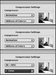
It should be noted that not all digital images can carry an alpha channel, and that some video codecs can support alpha channels while others cannot. Most applications require you to save an image in a format that supports alpha channel data. You can tell if a format supports alpha channels if the format you are saving in allows you the choice of “millions of colors +”, the plus indicating that an alpha channel is present (Figure 6-24). Most applications can read and utilize alpha channels, Final Cut Pro included, and many use alpha channel transparency information for processing transparencies as we are doing without informing you that the process is taking place.
Unfortunately the Apple DV codec does not support alpha channels. Although we are working with them in Final Cut Pro, the media files on our Scratch disk actually do not contain alpha channels. Final Cut Pro is adding them to the clips only for use in the application. If you need to export a video file for use elsewhere in another application and you want to send an alpha channel with that file, you need to export it using a codec that does support alpha channels (e.g., the Animation codec).
Although an alpha channel does also use grayscale luma information to carry transparency data about the image, it is not the same sort of matte as a luma matte. We will use our text clip again as an example of the way that alpha channels can show information that does not display when a luma matte is being used.
Adding a drop shadow to the text for accentuation
Although our Travel Matte-Luma does its job, it looks a bit flat and one-dimensional. We will add a drop shadow to the image for the text matte. First, we’ll attempt to follow the intuitive method of simply adding the drop shadow to the luma matte already in place.
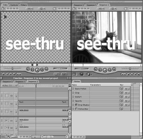
STEP 33
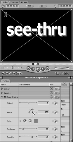
Double-click the text clip and bring it up in the Viewer window. Go to the Motion tab and look for the Drop Shadow parameter (Figure 6-25). Click the checkbox to enable the drop shadow effect.
As we adjust the settings here, make sure that the Viewer and Canvas windows are in sight to keep up with what your changes are doing across the application.
STEP 34
Set the Offset value at 5, and drag the Brightness value for the HSB Color control down to 0 to describe a substantial, believable shadow. Although our matted shadow will not be black, the strength and density of the shadow must be accurate for the drop shadow to appear real. Set the Softness value at 15 and the Opacity value at 75 percent (Figure 6-26).
Set your background in the Viewer window to Checkerboard 1 or 2 so that you can accurately gauge the strength and depth of the drop shadow. The drop shadow as it appears in the Viewer window should look nice and robust. The contrast between the very dark shadow and the very light text gives the text a multidimensional feel.
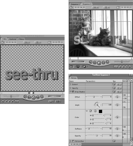
Unfortunately, a glance at the Canvas window will reveal that the drop shadow doesn’t even register. The luma matte we created to stencil the video clip is based on the white luma values of the text. Shades of black that dip below that level of white simply aren’t matted in at all. This unfortunately includes that nice healthy drop shadow.
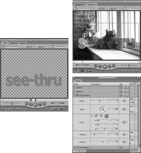
Adjust the Font Color of the drop shadow in the Motion tab, bringing the Brightness level up to 50 (Figure 6-27).
In the Canvas window, the drop shadow is now becoming a part of the matte, as the color of the drop shadow approaches the white that the luma matte works with. But it also looks unacceptable. The matte is very rough-edged, and it is difficult to distinguish between the matte of the letters, which should be solid and crisp, and the drop shadow, which should be darker and softer, mimicking a change in focus as well as opacity.
This is where the alpha matte comes to the rescue. When you created the text clip, Final Cut Pro discreetly created an alpha channel in the text clip to allow the sequence to translate the empty areas of the clip as transparent. This alpha channel is just sitting there, coming into play only when called for.
Viewing the alpha channel
The normal view for these windows is in RGB, which we have described as the ordinary color range of digital images. But Final Cut Pro offers two additional viewing modes to let you see what is in the alpha channel as well—RGB, Alpha, and Alpha+RGB.
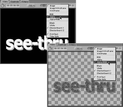
Load the text clip in the Viewer window and revisit the Wireframe drop-down bar. Below the Wireframe mode selections, you will find three choices for viewing the clip: RGB, Alpha, and Alpha+RGB. Switch the Mode to Alpha (Figure 6-28).
As we said, the normal mode for watching a clip is RGB mode. But if we switch it to Alpha, the view changes to a black and white image. These are not the colors you will see. This is the exact transparency information for the clip; it is the mask unmasked. Any areas that are white in the alpha, such as the text, are completely matted. Any areas that are black will be totally transparent. The bonus here is that with the alpha channel, there are 256 levels of gray for defining partial transparency of the image or matte. The drop shadow appears in the alpha channel with exactly the strength it carries in the actual RGB image, even though the color is reversed here. When you are using colors other than black and white, it may not even be related on the color wheel.
Viewing in alpha mode can be difficult if your clip contains imagery that is not directly related to the alpha channel. In this example, the imagery is the text, which is also where the alpha channel is. But since the alpha channel can carry transparency information about any area of the image, you might need to see the alpha channel and the RGB channels at the same time so that you can determine the relationship between the alpha channel and the RGB channels.
STEP 37
Revisit the Wireframe drop-down bar. Switch the Mode to Alpha+RGB. Switching back and forth between RGB and Alpha will not give you this sort of perspective, so Final Cut Pro offers a third viewing mode—Alpha+RGB. When viewing in this mode, the RGB data is visible, making the image appear as it would in RGB mode. But any areas that contain alpha channel matting information, such as the white and drop shadow areas of our text clip, show as pink. The brilliance of the pink areas describes the gray level to which transparency will be applied to the area. Areas that are not pink are areas that are fully transparent.
To fully appreciate the difference between the Travel Matte-Alpha and the Travel Matte-Luma, viewing on a black background is best. We will temporarily turn off track visibility for the Video 1 track, which is presently our background video clip.
STEP 38
Go the sequence and click on the green track visibility light for the Video 1 track at the extreme left-hand side of the Timeline window (Figure 6-29). This does not affect the contents of the sequence at all; it only hides the Video 1 track from view. You can turn track visibility back on at any time to make that track visible again.
Now that you have a black background, look at the Canvas window and view the text clip with the present luma matte, taking one last glimpse at the hard edges and lack of drop shadow in the Viewer window view of the clip. Now we will switch the matte from luma values to alpha values.
Setting the Travel Matte-Alpha
STEP 39
Select the video clip in the Video 3 track, the clip we are matting into the text layer (Figure 6-30). Go to the Modify drop-down menu, choose Composite Modes, and select Travel Matte-Alpha.
Instantly, the drop shadow smoothes out behind the text matte, this time with the soft, blurred edges that resemble the drop shadow of the text clip. This is possible because the alpha channel can more accurately assign levels of transparency based on the level of gray in the alpha channel, although it does not have to interact with the actual levels of gray in the RGB image. Since the luma matte must make its transparency matte from the gray levels in the RGB image, adjusting the transparency amount will affect what you see in RGB mode, and therefore out to video. The alpha channel simply makes whatever it covers transparent, no questions asked.
Turning the visibility of the Video 1 layer back on reveals that even on a video background that has less contrast than the black one, the difference between the two drop shadows is sharp (Figure 6-31). A proper understanding of the alpha channel system will allow you to extend this to other areas of the application, pulling off matting stunts that would otherwise require much more complex workarounds to be done at all.
As you work with other effects, keep in mind that most of them are simply combinations of alpha channels automated as plug-ins by Final Cut Pro. When you choose a color to key out or you create a garbage matte, you are only giving Final Cut Pro a different set of parameters for establishing the transparency of areas within a clip. Once again, there is more than one way to skin a cat, and sometimes you will get more acceptable results by constructing your own alpha channel mattes than by using a plug-in from the Effects Filters set. And remember that you can construct matte clips in Photoshop and other image-editing applications. As long as it carries an alpha channel, any shape or image you create can become the Travel Matte-Alpha clip.

Special effects: motion effects
Motion for clips
In the preceding chapter, we experimented with keyframing in the Timeline window, as well as adjusting the physical properties of a clip from within the Viewer window’s Motion tab to create the drop shadow effect. But we have yet to fully explore the functionality of Final Cut Pro with regard to the many other physical parameters for a clip or the ability to keyframe them to achieve interesting effects that change over time. We will now move a little further with each of these ideas, learning to fully manipulate a clip within a sequence. If you can see it in your head, you can do it in Final Cut Pro.
To begin with, we will use the text clip we used in the previous chapter, but this time without the Travel Matte applied from the Video 3 layer clip. You can either click the green track visibility light to hide layer 3 or just select the Video 3 layer clip and delete it from the sequence. When you do so, your text clip will pop back into the Canvas as an actual graphic text element rather than a matte for a video clip (Figure 6-32).
The main reason we will be using a graphic element like a text clip is that some of the subtleties of the physical properties we are about to adjust are difficult to see in a full-frame, full-motion video clip that also contains motion in itself and covers so much of the viewing area that it obscures what you have adjusted. This does not mean that the physical properties we will toy with here have no effect on video clips; the physical properties we will alter in the text clip are simply easier to distinguish than if applied to a video clip. Once you understand how the properties work, you can apply changes wherever you want throughout the system, even to an entire sequence at once.
Double-click the text clip and load it up into the Viewer window. For the moment, we will leave the Control tab alone and leave the text formatted as it is. Click and drag the Motion tab away from the Viewer window so that you are able to view it, the Viewer Video tab, the Canvas window, and the Timeline window simultaneously (Figure 6-33). This may take some shuffling of your Desktop space and re-sizing of windows; once again, you become aware of the benefits of having multiple monitors in your editing setup.
This is one of those times when you will really appreciate the Macintosh’s ability to easily integrate two computer monitors into the workflow. Although you can get by with one monitor, you can wear out your wrist moving windows around to get at other windows.
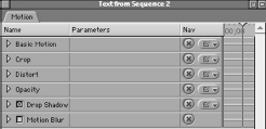
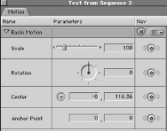
Let’s take a look at the various physical attributes in the Motion tab of the Viewer window that we can work with in a clip. Each attribute has a set of specific controls or parameters which relate only to that attribute. To get at the parameters for an attribute, click the little triangle to see its drop-down parameter list. From the top, the attributes are Basic Motion, Crop, Distort, Opacity, Drop Shadow, and Motion Blur. We will cover each of these attributes separately, adding up their combined effects to the text clip until we have a text flyover that really flexes Final Cut Pro’s compositing toolset.
STEP 41
Basic Motion; Scale
The first attribute is Basic Motion. Click the drop-down triangle and review the parameters. Examine the first parameter, Scale (Figure 6-34).
Although Scale does not seem directly related to motion, bear in mind that motion is a basic concept in dimensional space. Motion as we see around us in the real world takes place in three dimensions: side to side, up and down, and also closer and further away from our position as the viewer. But the video frame we are compositing with exists only on a two-dimensional plane. That is to say, there are only left and right and up and down.
To simulate the third dimension of real-world movement, we have to control the scale of the object we are working with. When an object is closer to us, it appears to be larger than when it is further away. Thus by adjusting the Scale parameter, we can make an object seem to be closer than other objects or approach the viewer over time.
Next to the word Scale, there is an adjustment slider. The default value for this will always be 100 percent, since Final Cut Pro always assumes that we intend to use the object at the original size it was created. For precision purposes, there is also a numerical entry field next to the slider.
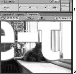
Click on this field and enter 400, increasing the scale of the text to 400 percent. When you hit Enter, the text size will jump to a much larger size, extending past the edges of the video frame in both the Viewer and the Canvas windows (Figure 6-35).
Do not be concerned that the text outside the frame is not visible; it is still intact, only outside the viewing area of the frame. Changing the value back to 100 percent will reveal that the text is still there. Likewise, if you drag the slider down to zero, the text disappears, since it is now being displayed at 0 percent of its normal size. The range of scale goes from 0 percent to 1000 percent.
STEP 43
Take the slider up to around 1000 percent and take a look at the text. If you see no text in the frame, it is because you are looking at the space between the letters, which has also been magnified along with the text itself. Moving the text clip around using the Selection tool will bring some of the text back into view.
One thing you will notice is that the text no longer looks presentable at 1000 percent. The edges that you can see have taken on a pixellated appearance that is reminiscent of what we saw when the Viewer window or Canvas window was viewed at percentages higher than 100 percent. But unlike those instances, this time the effect will be seen in the resulting video out to Firewire, since this is an effect we are manipulating in the clip with rather than a video preview window on the computer screen.
Once again, Final Cut Pro is being asked to interpolate or make up information about the object, information that was not originally present. When you created the text clip, you chose a font size and other settings for the text that determined how large it would appear when viewed at 100 percent in the Viewer and Canvas frame windows. But when you increase that size using the Scale attribute, Final Cut Pro has to make up the information that was not included, resulting in pixellation and blockiness.
Unfortunately, there is no way around this. You have to plan ahead when you create your text or other graphic images for the largest possible size they will be required to display in the frame. The good news is that you can down-sample (i.e., decrease the scale of the text) without any perceptible loss of detail. So if you create your text at the largest necessary size, you can later scale the image down to the specific size you need. The lesson here is that Final Cut Pro can throw away data and reduce the scale to yield acceptable results, but increasing the scale above 100 percent usually results in unacceptable pixellation.
Since the Controls tab of the text clip in the Viewer window is conveniently available, we can easily test the correct method for getting large acceptable text.
STEP 44
Pull the Scale in the Motion tab back down to 100 percent, so that when we bump the size of the text, we don’t explode it out to 100,000 percent of the present size (Figure 6-36)! Next, tear away the Controls tab from the Viewer window and place it on the Desktop so that we can adjust it and watch it update in the Viewer and Canvas windows. In the Size field, enter the number 400.
Instantly, the text in the Viewer and Canvas jumps to a much larger size that does not display the pixellation of the previous scale increase.
But once again, there is a problem that may not be immediately apparent. When you enlarge the size of the text in the Viewer window, it extends past the edge of the clip’s video frame, as you would expect, since it is now too large to fit within the frame. If you move the Wireframe around in the Viewer or Canvas window, however, you will see that the edge of the frame from the Viewer window now cuts off the text that extends past the edge of the Wireframe. Although the text is still intact, as pulling the font size back down in the Controls tab will reveal, we cannot see beyond the edge of the clip’s frame size.
The Video frame, in either the Viewer window or the Canvas window, is like a mask for all the elements that are in the project. It can only show you items that fit inside the mask of the frame. Enlarging the Scale of the clip made the entire frame size larger, thus allowing us to move the clip around the smaller Video frame without encountering an edge. Even though we got pixellated results, we could move the frame around because the frame had been scaled up the same amount as the text.
But when you only increase the size of an object that lies inside the video frame such as the font of our text, rather than the frame size itself, you encounter the edge of the video frame. The frame stayed the same size, while the text extended past its edges. Bring the Font Size back down to 100 before moving on.
Although this may not seem problematic now, it will severely hamper your ability to use large good-looking text as a moving object in your sequences. You will need either to sacrifice some image quality to get the larger text size or to sacrifice heavy scale and movement adjustment of the text clip. Generally, the best trade-off is to sacrifice some image quality rather than the ability to adjust scale and movement. If your technique and timing are good, you can use other elements, which are explored subsequently to hide the image degradation.
Pan and Scan for large images
A still better solution is to use another dedicated image-editing application that is not restricted to the video frame size that Final Cut Pro needs to work in. This is the primary reason for the popularity of Photoshop among Final Cut Pro editors and its resulting tight integration into the application by the fine people at Apple who wrote the code.
Using Photoshop, you can generate text and other graphics images that are not restricted to the 720 x 480 frame size that Final Cut Pro’s text editor conforms to, up to a limit of 4,000 x 4,000 pixels. Such images are easily integrated into the sequence as clips just as the internal text clip was, and in the formats described in Chapter Four on importing media. Where the internally generated text clip showed its edges when moved around the frame, a Photoshop-generated image with a frame size of 1440 x 960 could be moved easily around the 720 x 480 video frame eliminating the edge problem encountered using the Final Cut Pro Text Generator clip.
This technique is sometimes referred to as Pan and Scanning, since you can move a larger image around a smaller frame to focus on what you want, just as if you were panning a video camera to select what you want in the frame as you shoot. Pan and Scan is often used in converting motion pictures to video that have a wider aspect ratio than the television’s 4x3 rectangle. If letterboxing is not used to help fit the entire wider image on the screen at once, filmmakers sometimes resort to showing only part of the frame at a time. If they want to show the other part of the frame for some reason, they can Pan and Scan to the other side of the frame.
If you do not yet use an image-editing application such as Photoshop, but you plan to work with graphic elements a great deal, you may want to start considering your options. Using a dedicated application to generate your graphics has a profound effect on the quality and aesthetics of your finished products, besides opening up the motion and scale possibilities previously described.
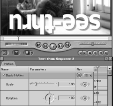
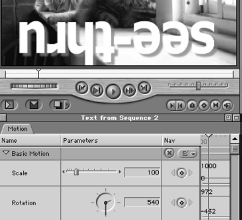
The second parameter for Basic Motion is Rotation. The setting can be entered either using the directional dial, or by numerical entry. Either way, the value entered is that of degree of rotation between 0 and 360. If you type in the value 180, your text layer will flip upside down as it is rotated 180 degrees from the present position (Figure 6-37). Entering 0 will return it back to its proper orientation in the frame.
There is a further dimension of rotation that can be understood by looking at the dial. If you enter a value higher than 359, you are actually entering a degree of rotation that includes a complete rotation and begins the second one. So entering the numerical value of 540 will land the clip upside down, having rotated the clip one and a half times.
STEP 45
Enter 540 into the Rotation field to demonstrate this behavior and then look at the dial (Figure 6-38). A small red hand on the dial will indicate that more than one rotation has occurred.
It may seem less than obvious why one would want to rotate an image more than 360 degrees, since the end result will still be a simple degree of turn for the clip. This is because when we keyframe the rotation, we will be able to specify how many times it completes a full rotation on its axis between two moments in time, as well as the actual degrees of rotation that it begins and ends with. The flexibility of being able to keyframe the number of complete rotations as well as beginning and ending values will define our ability to speed up or slow down the spin of an object, based on the number of times it spins over a specific duration.
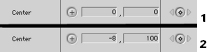
The next parameter, Center, is perhaps the most obviously vital component of motion (Figure 6-39). Center defines the two-dimensional physical position of a clip in the frame, based on the standard geometric coordinates of the X and the Y axis. The numbers on the X axis determine horizontal position, and therefore motion to the left and right. Numbers on the Y axis determine vertical position, and therefore motion up and down.
Since the X and Y axes work from geometric standards, the coordinates 0, 0 are for the geometric center of the screen. Positions to the left of center on the X axis are described with negative numbers; similarly, positions above the screen center on the Y axis are described by negative numbers. When a clip is moved, the X and Y values of the Center parameter in the Motion tab change based upon the new position inside the video frame of the Canvas window.
Although this was useful in a static sense, as it was in the correct placement of our text clip in the last exercise, it takes on primary importance in keyframing motion paths. It is the Center parameter that defines where the clip is at any time during its playback. If you keyframe that position over time, you will be able to create a basic motion path.
The Anchor Point parameter offers an unusual flexibility that changes the clip’s relationship with all the other parameters in the Basic Motion attributes (Figure 6-40). The Anchor Point works more or less as a central point or axis for each clip. All other parameters function based on what the clip has assigned for its true center, or Anchor Point. This Anchor Point does not affect anything outside the clip, and, unless changed, it will always default to the exact center of the clip, which is why it is often sorely underused by editors who should know better.
Its influence is most plainly seen when combined with Rotation values. For example, a round plate whose Anchor Point is directly in the center will spin in place like a wagon wheel when rotated. But when the Anchor Point is moved out to the edge of the plate, the rotation will make the plate itself rotate around a point in space on the edge of the plate. This makes it easier to mimic the real world motion of lop-sided objects whose center of gravity is not defined by the center of their surface. The Anchor Point is, as usual, key-frameable, meaning that you can alter the Anchor Point of a clip over time to yield interesting new effects based on the other clip’s parameter’s reaction to the Anchor Point change.
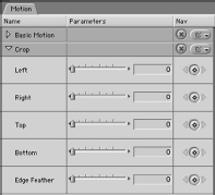
Crop Settings
The next attribute in the Motion tab is Crop Settings (Figure 6-41). The crop settings are interesting in that they allow you to hide a section of a clip from view without having to insert a matte of any kind. This can be convenient for operations such as displaying only a section of a larger graphic image or video clip inside the frame. Rather than change the scale of an image to make it smaller, which would still include detail you may want to leave out, the Crop attribute simply limits how much of the frame of the clip is visible.
The parameters for this are adjustable as a square or rectangle, based on the left, right, top, and bottom edges of the clip.
![]()
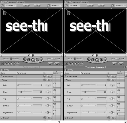
Click and drag the slider for either the left or right edge and drag it to around 25 percent (Figure 6-42). You will see that half of the frame of the clip has been obscured. The other half is not resized, as it would if be you had changed the actual width or scale of the clip as you will be able to do with the following Distort attribute.
The last parameter for the Crop tool is Edge Feather. This allows you to soften the edge you are cropping the clip with so that the image being cut off with the tool fades into the background now visible on the other side of the crop line. This can be displayed by moving the crop line directly over one of the letters in the text clip were are adjusting. Drag the left or right slider such that one of your letters is seemingly cut in half. Set the Edge Feather at 50 percent and you will see the cutoff soften such that the letter appears to disappear into the background.
All transparencies, including the Crop tool, are an effect of unseen integrated matting. The soft, feathered edge you are witnessing is the result of Final Cut Pro allowing some pixels to be seen and others to become transparent along the edge of the crop. The value you enter into the Edge Feather field simply informs Final Cut Pro how far outside of the crop edge to apply the gradual mixture of visible and matted out pixels. The effect is rather pleasing, having a soft edge, and when the Crop parameters are keyframed, it can be used for a gentle, gradual revelation of imagery in the composited sequence.
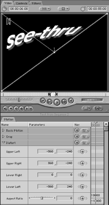
Distort
The third attribute, Distort, is a powerful tool for altering the very shape and aspect of a clip (Figure 6-43). Unlike the Crop attribute previously described, the Distort parameters change the actual size and shape of the clip in the frame by altering its physical dimensions rather than by covering them up. The effect is rather like having an image imprinted on a rubber balloon. As you stretch and release the rubber, the image changes its appearance as well, resulting in very precise distortions based on the amount of stretch applied to the edges of the material.
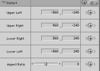
The first four parameters of the Distort attribute are Upper Left, Upper Right, Lower Right, and Lower Left. These parameters correspond to the corner points of the clip’s frame. There is no slider adjustment to these parameters because the points exist as X and Y coordinates and, therefore, can be assigned to any location in the frame. Interestingly, they can even be assigned between the other points, so that the clip appears to double back on or fold up into itself.
STEP 47
To display this type of clip distortion, enter 0 and 0 as the new X and Y coordinates for the Lower Right parameter (Figure 6-44). The Lower Right corner of the clip will jump to the center of the video frame, which carries the coordinate value of 0,0. Not only has the shape of the clip changed, but the text within the clip now appears curved and scrunched as a result of its position in the frame and based on the amount of virtual squeezing of pixels to adjust and fit them all inside the new frame shape.
Notice that although we are still looking at a two-dimensional text image in the frame, the simple change in shape and curvature suggests three-dimensional depth. This is another example of using the alteration of two-dimensional shapes to suggest natural depth perspective. The Distort parameter allows us to mimic the real-world perception of change in size and shape that tells our brain that an object is nearer or farther away.
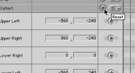
STEP 48
To remove the Distort effect and to return any coordinates of any attribute or parameter back to their original positions, hit the red X parameter reset button just to the right of the attribute’s name (Figure 6-45).
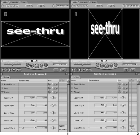
The last parameter of the Distort attribute is called Aspect Ratio. It is adjusted by a slider, with a default value and unaltered setting of 0. The Aspect Ratio changes the degree to which the clip in the frame is distorted two-dimensionally. Dragging the slider to the left reduces the Aspect Ratio of the clip, making it appear shorter and fatter evenly across the horizontal plane. Dragging the slider to the right increases the Aspect Ratio so that the clip appears taller and skinnier once again, evenly distributed across the vertical dimension (Figure 6-46).
The reason this parameter is referred to as an Aspect Ratio instead of a Short/Fat–Tall/Skinny tool is that it was initially most useful in taking footage shot anamorphically to yield a widescreen, cinematographic look with letterboxing. Many cameras allow you to shoot in a 16x9 mode, which introduces letterboxing at the top and bottom of the frame. The difference in screen shape can yield interesting effects, so many videographers use it when shooting.
Unfortunately, older versions of Final Cut Pro could not decipher the difference between regular footage and 16x9 Widescreen. After all, anamorphic 16x9 footage is simply footage that is stretched in the camera. Final Cut Pro could not read the file data that the cameras inserted in 16x9 footage specifying that the footage had been anamorphically recorded. The result was tall, skinny images that fit within the video clip frame size but were obviously distorted.
Although many of us would love to maintain the skinny figure that anamorphic footage gives us, we needed a way to get the clip back to an accurate relationship between the clip’s height and width, otherwise known as the Aspect Ratio. 16x9 and 4x3 are common Aspect Ratios for video, and we saw that there are others that were available when we set up the Audio/Video Settings earlier in this book.
The Aspect Ratio determines not only what shape the frame size of a video or film is, but also whether or not the video or film frames displayed in the frame are shaped correctly. In film and some video cameras, the Aspect Ratio is stretched up by the lens, which determines the shape of the image recorded on the film stock or video CCDs. With other video cameras and software such as Final Cut Pro, the Aspect Ratio is determined by how the system organizes the digital bits of each frame. Either process results in an anamorphic image, from the Greek ana, or Up, and morphë, or Shape.
With Final Cut Pro version 1.2.5, the application gained the ability to automatically detect and correctly reshape 16x9 footage without using the Aspect Ratio parameter of the Distort attribute. The tool can still come in handy, however, to change the Aspect Ratio for other reasons, such as correcting typographic elements, reworking improperly processed footage that has been printed or telecined at the wrong ratio or for any other situation that requires an adjustment to be made evenly across the frame on either a horizontal or vertical plane.
The next attribute, Opacity, has been explored in the discussion of the sequence Timeline, and we have already set keyframes for it there (Figure 6-47). If the clip for which we set keyframes for Opacity were presently loaded into the Viewer window, this is the location in which those keyframes would be displayed. Alone among the Motion attributes, Opacity can be set from the Timeline.
Even though it may seem easier to set Opacity keyframes in the Timeline, fine-tuning them should always occur in the Motion tab of the Viewer window. This is because the timing of Opacity keyframes frequently coincides with that of other keyframes (e.g., Basic Motion and Distort) to produce profoundly three-dimensional effects that really seem to move from far away to near at hand.
Why is this so? Although your eyes are generally too sensitive for you to notice it, you detect very definite differences in the amount of light something reflects. This difference tells your brain about how far away an object is. An object very far away reflects less light into your eye. Although you do not think about this when viewing objects, the part of your brain that does the work of perception does.
This is not really news to anyone who works with light for a living. Photographers, videographers, and cinematographers all know about the fall-off of light as you move away from its source. It follows a definite mathematical formula, referred to as the inverse square law. This physical law states that as the distance between you and a light source doubles, the amount of light making it to you is quartered. The amount of light you receive from a light source drastically decreases as you move away from it.
Those who live by the camera must deal with this in order to get the proper exposure when they shoot. But it is also valuable information to us when attempting to create believable three-dimensional distances between objects in our video animation. When an object should be closer to the viewer, it should be very bright and near 100 percent opacity. As it gets further away, its reflectivity should drop, leading to decreased opacity. Put simply, further away should be harder to see, and not just because the object is smaller.
As you change the scale and position of an object, you will likely change its opacity as well to increase the perception that not only is the clip getting larger as it approaches the screen, it is getting brighter. The touch of realism that adjusting opacity gives is subtle but every bit as important as any other attribute you adjust in the clip.
Drop Shadow
The next attribute, Drop Shadow, is a fast, convenient tool for adding depth and dimensionality to an image with no muss or fuss (Figure 6-48). It must be enabled by checking the box next to the name, otherwise it will not be present. Drop Shadows are like an unspoken signpost that an object stands out closer to the viewer than the ones behind it. It is a truly paradigmatic symbol of three-dimensional images, because even though most drop shadows are really very primitive and out of place in the context of the image they accompany, they still give the sense of depth they are used for.
We have already used the Drop Shadow in our discussion of Composite Modes and Luma and Alpha Mattes. But it is worth mentioning that the controls for the Drop Shadow are keyframe-able as well, allowing some flexibility in the Drop Shadow over time. Why leave the ubiquitous Drop Shadow simply sitting there in one position, when you can imply that time is passing by having the shadow change position as if it were being cast by the sun moving rapidly across the sky? Remember that no effect need remain static over time unless you have chosen for it to do so for reasons of aesthetics. The choice to leave a Drop Shadow alone should be made because the Drop Shadow shouldn’t move, not because it can’t.
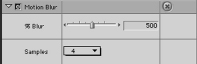
Motion Blur
The final attribute in the Motion tab is for Motion Blur (Figure 6-49). Like the Drop Shadow attribute, Motion Blur must be enabled by checking the box next to its name. Motion Blur is a unique effect that works only with elements in a composition that move. Motion Blur affects only the movement of items within Final Cut Pro. A clip moving across the Canvas window can display Motion Blur, but a clip that is stationary in the center of the window cannot.
Items such as film and video footage that display natural motion blur in their own original frames will not be affected by motion blur settings unless their entire clip moves in the larger video frame. Motion blur is applied to entire clips rather than any separate part of a clip’s frame. Therefore we will be able to add motion blur to our text image when we move it across the screen, although we could not add it to any object inside the static video clip in the background.
But what is motion blur? Motion blur is a phenomenon that occurs when an object moves faster than the perceptual frame rate of the viewing camera or eye can gather still images. As we said early in this book, video and film are simply a series of still images that update so rapidly that the viewer perceives continuous moving objects rather than a series of images of still objects. If the frame rate slows down too far, we see the still images individually, and the illusion of continuous motion is broken. Speed up the frame rate, and the illusion becomes stronger and sharper.
At around 24 frames per second, which is the standard frame rate of film, the illusory motion becomes fluid, each frame being nearly indistinguishable from the previous one. Slightly faster, PAL video uses a standard frame rate of 25 frames per second, very close to the film frame rate. NTSC video uses an even faster frame rate, increasing it up to 29.97. Since both PAL and NTSC video are interlaced formats that scan each frame as two separate fields sequentially, the true frame rate should really be regarded as double this number, as fast as 59.94 individual fields per second.
What does this have to do with motion blur? Motion blur occurs whenever an object passing in front of the camera or eye moves too fast for the viewer to actually record each increment of the movement. If you pass your hand in front of your face quickly, you will see a blur of your hand, because your eyesight is gathering image information at a relatively slow frame rate. In the fraction of a second that your eye gathers an entire frame’s worth of visual information, your hand has actually moved several inches or several feet, depending on how fast you move it. For those few fractions of a second, you see your hand in all the places it has traveled since the beginning of your eye’s gathering of the visual frame.
For our eyes, this is nothing new, and aside from some interesting optical illusions based on spinning wagon wheels and such, we are quite used to what our eyes can and cannot perceive sharply. But where motion blur really takes on significance is in the field of image gathering. Photographers and cinematographers must take care that when they record images, the shutter speed, which is the part of the camera that determines how long the image gathering period lasts, is fast enough to overcome excessive motion blur. If the shutter speed is too low, there will be so much movement between the beginning and the end of the exposure that there will be nothing but blur in the frame.
Still photographers have to be more careful than the rest, because the shutter speed for still cameras is a choice to be made by the photographer based on many factors, the most important of which is the desired effect. The photographer can add or take away motion blur by changing the shutter speed. For still photographers, motion blur is an important effect that can be used to deliver a sense of duration and motion in a still image.
Film and video, as we have said, have standard frame rates, making this less of an issue. Although shutter speeds can still be customized to add or take away motion blur, generally speaking there is a normal, definitive amount of motion blur that occurs in footage shot with a shutter speed that matches the frame rate. With video, which is composed of two interlaced fields for each frame, the shutter speed is a fiftieth of a second for PAL and a sixtieth of a second for NTSC, such that the shutter speed more or less doubles the frame rate and matches the field rate. For film, which is noninterlaced and does not use field doubling, this is 24 frames per second (Film motion blur can be further increased or decreased by the shape of the shutter itself. An iris-shaped shutter allows the cinematographer even more control over motion blur. This is not a function of the frame rate though, and does not concern us here).
As with Drop Shadow, Motion Blur must be checked ON to be applied to a clip. There are two parameters for Motion Blur, the percentage of blur and the number of samples. The percentage of blur lets you tell Final Cut Pro how intense the motion blur should appear. Final Cut Pro creates motion blur by taking a certain number of frames before and after the frame in question and blending them together, just as we said your eye gathers image information about where you hand was over the entire period it gathered a single “frame” of vision.
The result is that you see a mixture of where the object is in the frame now with an image of where the object was just before and after the present frame. Since the blend across the frames is smooth and is reblended with each new frame, you get an effect not unlike what real motion blur does: you are kept from getting a tight focus on each position of the object within each frame.
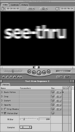
Although it would seem like a bad idea to obscure focus, motion blur can add realism to moving objects that otherwise appear not to be visually integrated into the frame. We can’t help it; when we see motion blur, we assume that an object really moves through space, even if that object is a two-dimensional text image crossing a video screen. Since our job in compositing is to mimic reality on a two-dimensional plane, motion blur is an essential part of any movement we add to our compositions. Some experimentation will prove this point; although until we have a moving clip as in the next example, Motion Blur will not appear to have any effect.
Percentage of blur increases or decreases blur by adjusting the range of previous frames that the blur blends into the frame when Motion Blur performs the act just described. The scale of percentage ranges from 1000 percent, which blends ten frames of the clip into the blur, to 0 percent, which blurs none. 100 percent blends only one frame. The default value of the percentage is 500 percent, which gives a healthy “standard” blur (Figure 6-50).
Sample refers to how detailed the blending process is in calculating the motion blur. More samples will result in a much more fluid blend between the individual frames that are being joined to create the blur. Fewer samples means that the blend may look a little rough, since very few positions between the number of frames being sampled are figured in. The bottom end of fluid samples is 4, which looks pretty rough. A setting of 32 looks fantastic. The trade-off is that the larger the number of samples, the longer it takes Final Cut Pro to calculate and render the frame. With 32 samples, this can take several seconds. With 4, the calculation is quick. A setting of 8 or 16 usually gives the best balance between speed and quality.
Making the motion
Now that we know what each of the attributes does, let’s go through and use them on our text clip in the sequence, this time including keyframes to get a sense of how values can change over time in our sequence, as well as in society at large. First, make sure that you have a clean text clip trimmed out to at least six seconds in length edited into the first frame of a sequence. You don’t really need a video clip in the background for this example, but you may find that it adds a dimensionality to motion and other attributes that is difficult to achieve with monotone backgrounds. Feel free to add another video clip to the sequence, although you may want to disable its visibility while setting the motion keyframes for the text clip.
We will create a bit of motion with this text that uses all our attributes. The text will start dimly seen and far in the distance. As it approaches the viewer, it will spin around. When it reaches nearly screen size, it will spin around one more time, although this time with a different axis. Finally it will come to a rest in the center. At any time you can check on the way your keyframes affect the sequence with a quick render using the selection tools we discussed in the preceding chapter.
If a setting doesn’t make sense, clear off your keyframes for that attribute by Control-clicking the keyframe and selecting Clear (Figure 6-51). Once all the keyframes are cleared for an attribute, lay them out again correctly and you will get the results you want. If you still have trouble, just enter the numbers offered here and work backward through the process, advancing frames and looking at the effect that each keyframe has on a particular frame.
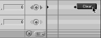
Preparing the project for the motion settings exercise
STEP 49
Move the sequence playhead to the beginning of the text clip. Now double-click the text clip so that it loads into the Viewer window. Make sure that the title line in the Viewer window reads “Viewer: Text from “nameofyoursequence” (Figure 6-52). If it does not, you may be keyframing the wrong clip! Remember that Final Cut Pro will allow you to keyframe any clip or sequence that is loaded into the Viewer, regardless of whether it is the one you want to work with in the sequence. Keep your eyes open.
STEP 50
When your text clip opens in the Viewer, its playhead will be located on the same frame of the clip that the playhead in the sequence and Canvas are parked on. Do not move this just yet, because we are going to set our first keyframe on this frame. Grab the Motion tab from the Viewer window and drag it to the side so that you can make your settings there while watching the update in the other three windows.
STEP 51
After you tear the Motion tab away from the Viewer window, reshape the Motion tab window into a short, wide window by tugging on the reshape tab at the bottom right-hand corner of the window, so that you have complete access to the Motion tab’s own Timeline (Figure 6-53).
Not surprisingly, this Timeline uses the same navigation conventions that the sequence Timeline window uses. The difference of course is that this Timeline shows only the clip loaded into the Viewer window. Instead of layers, this Motion Timeline is divided into the various attributes and parameters we just finished going through.
![]()
Notice that there is a light gray and dark gray area of this timeline (you may have to adjust the time scale of the Motion Timeline to see this). Light gray indicates any area in the sequence Timeline window in which the clip is present.
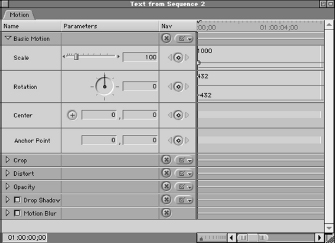
STEP 52
Hit the Down Arrow key to move the playhead to the end of the clip, and you will see that the playhead jumps to the end of the light gray area (Figure 6-54).
Why would Final Cut Pro not chop the Motion Timeline off at the end of the clip? The answer is functionality. Final Cut Pro will allow you to set keyframes for a clip in an area beyond the actual duration of the clip. This gives you even more options when determining the keyframe values and their positions, as well as keeping your keyframes safe should you accidentally trim off the end of a clip where you had previously inserted keyframes.
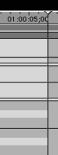
The first keyframe we will set is for Scale.
![]()

STEP 53
Return the playhead to the first frame of the clip by hitting the Up Arrow key. In the Motion tab index, just to the right of the Scale percentage field, is a small button containing a diamond. This button is for setting and removing keyframes. Click the button and watch as the diamond changes to green (Figure 6-55).
Whenever the playhead is parked on an attribute or parameter keyframe in the Motion Timeline, this diamond will turn green. Hit the Right Arrow key to move to the next frame, and the green light disappears. Hit the Left Arrow key to return back, and it lights back up.
The keyframe we have just set has the value of 100 percent scale, which was the default value for scale in the scale percentage field next to the keyframe button. As described previously, a single keyframe is no different from having no keyframes at all. Keyframes have an effect only when there is a change in value, and that requires two keyframes.
To set the second keyframe, let’s move to a new position later in the clip.
STEP 54
With the Motion tab window active, type +400 and then hit Enter (Figure 6-56). Just as with the sequence Timeline, this moves the Motion Timeline playhead up four full seconds.
STEP 55
When your playhead is parked at the fourth second, click the keyframe button again. Once again, it inserts a keyframe on the position of the playhead with a value of 100 percent (Figure 6-57). You now have two separate keyframes on the Motion Timeline in the Scale parameter.
But this does not change anything in our clip, because both keyframes carry the same value. In our example here, we want the text to start out very small and grow larger over time so that it appears to approach from a distance. We need to return to the first keyframe and assign it a different value.
We could hit the Up Arrow key to move the playhead to the beginning of the clip where our first keyframe is, but there is a faster way, especially if the keyframe you are going to is not directly on the beginning or end of a clip. If you have more than one keyframe in the Motion tab timeline, the keyframe button will display a sideways triangle pointing in the direction of the next keyframe from where the playhead is currently parked (Figure 6-58). If the playhead is parked between two keyframes, triangles will appear pointing in both directions. If there is no keyframe on a side of the playhead, the triangle will be grayed out. Clicking on the triangle will move the playhead to the next keyframe in that direction, eliminating the need to scrub around with the playhead and wait till the keyframe button turns green.
![]()
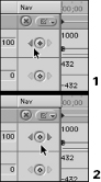
STEP 56
Hit the left triangle to return the playhead to the first keyframe of the Scale parameter. There are three primary ways to change the value of an existing keyframe. The first is simply to change the value in the field.
STEP 57
With the playhead parked on the first keyframe in the Scale parameter of the Motion Timeline, type 10 into the Scale field, then hit Enter (Figure 6-59). When you do, the green line between the keyframes slants, showing in a linear fashion that there is now a difference in value for the two frames separated by four seconds.
The second method to change the value is less precise, but it allows you to change the Timeline position of the keyframe in time as well as its value.
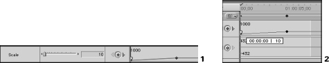
Hit Command-Z to undo, or simply type the value 100 back into the field to return it to its previous state. Move the mouse pointer directly over the keyframe until you see the arrow turn into a small crosshair. Click the keyframe, and drag in either direction. Up and down will change the value of the scale, and left to right will actually reposition the keyframe earlier or later in the timeline.
Using this method, you can reposition the keyframe in time as well as change its parameter value. If the numbers move a little too fast for your taste, simultaneously pressing the Shift and Command keys while clicking and dragging the keyframe will “gear” down the adjustment, allowing somewhat more precise control.
The third way is to manually adjust the scale using the Wireframe controls in the Canvas or Viewer windows. It is very imprecise, and should be used only when you are in such a hurry that visually estimating the scale change is the best you can do.
STEP 59
Make sure that the Canvas window is set to Image+Wireframe and that the text clip is selected in the sequence Timeline, so that you see the Wireframe of the text clip visible around the text in the window (Figure 6-60).
STEP 60
Set the Motion Timeline playhead on the keyframe you are adjusting. Then click and drag at either of the corner points of the Wireframe box in the Canvas window.
As you drag, the box will grow or shrink depending on the direction you are dragging. Also notice as you drag the corner point and change the scale of the Wireframe in the Canvas window, the value in the Scale parameter of the Motion Timeline in the Viewer window changes as well. Although you are making the adjustment in the Canvas window, you are actually adjusting the clip in the sequence which is loaded into the Viewer. Thus the Scale change is selected in the Viewer’s Motion tab. Such is the nature of global settings.
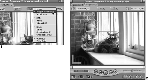
As you will be able to tell, this method is very imprecise, which is not a good situation when working with complex keyframes.
There are two important exceptions. If you want to set the clip’s scale nonuniformly (i.e., you want to make the height different from the width), perform this hands-on action with the Shift key pressed. This allows you to set height and width by dragging up and down and left and right respectively. Final Cut Pro accomplishes this by changing the Scale parameter and also the Aspect Ratio parameter of the Distort attribute at the same time. Of course if you want to keyframe this nonuniform shape change, you need to set an initial keyframe for both Scale and Aspect Ratio.
The other exception is for when you want to quickly set new values for Scale and Rotation simultaneously. This is great for creating animations of texts and other graphics that zoom and spin into the frame. Such animations require very tight coordination between the Scale and Rotation settings. If you set a keyframe for both Scale and Rotation parameters and then Command-click a corner point of the Wireframe box, you will be able to set the two values together and achieve natural spinning animations.
For the moment, set the first Scale keyframe’s value at 10 percent, using either method of entry. We will also be doing some extra interesting effects using the other attributes that will require a couple more Scale keyframes. The action of the other Scale keyframes will become understandable when all the keyframes for the other attributes are in place.
Our final spin in the animation requires that the last jump in Scale occur faster than the first. Therefore we will also set a keyframe at the third second, this one for a value of 50 percent. This means that for Scale, the text will grow from 10 percent to 50 percent over the first three seconds, and then from the third to the fourth second, it will grow from 50 percent to 100 percent.
This is to mimic the real-world perceptual phenomenon in which an object farther away appears to move much slower at high speeds than an object close by. As the text gets larger and closer to the viewer, its speed must seem to increase the way that a car’s speed appears to increase as it approaches us, even though the car’s speed maintains a steady 50 miles per hour.
STEP 61
Move the playhead in the Motion Timeline up to the third second by typing “+300” (Figure 6-61). Add a keyframe by entering a Scale value of 50 percent. Notice that after you create the first keyframe for a parameter, simply changing the value of it on a frame for which there is no current keyframe creates one.
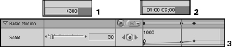
When your keyframes for Scale are properly set, they should look like Figure 6-62.
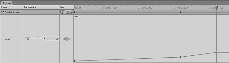
Figure 6-62 Correctly keyframed scale parameter motion timeline
Setting Rotation keyframes
The second parameter is Rotation. Although we won’t be making our text spin in more than one full rotation, we want to give the sense that as the text approaches us, it spins in from the side as well. We will set an initial keyframe at the beginning of the clip with the value of –90 degrees. Negative values for Rotation simply imply counterclockwise rotation.
STEP 62
Reposition the Motion Timeline playhead at the beginning of the clip on the same frame as the first Scale keyframe. Make sure that the Scale parameter’s keyframe button diamond is green to indicate the playhead is currently on that frame.
STEP 63
Click the Rotation keyframe button to create an initial keyframe, and then enter a value of –90 into the Rotation field (Figure 6-63).
With the initial keyframe set and the value entered, the Canvas window should now show the clip as a very small sideways rectangle near the center of the frame. Of course, as the text grows in size, we expect it to also straighten out.
STEP 64
Move the playhead up to the three second mark either by typing “+300,” or by hitting the right-side triangle next to the keyframe button in the Scale parameter. Our next Rotation keyframe will be on the same frame as the Scale one, so that would be the fastest way to navigate to it without searching.
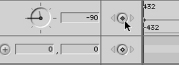
Once at the three-second point, we want to add a second keyframe. We could do this as we did the last three, by clicking the keyframe button. But the easiest way is to simply change the value of the parameter. If there is already an initial keyframe anywhere on the Motion Timeline for a parameter, simply changing the value of that parameter with the playhead parked on a frame that does not currently have a keyframe will automatically create a new keyframe there.
This does not work across parameters. There must be an initial Rotation keyframe, for instance, for this to work in the Rotation parameter.
So the process of setting a lot of keyframes for a parameter is to set the first keyframe with the button, and then go about your business setting new values at new positions by positioning the playhead and then entering new values by any method.
STEP 65
To set our new Rotation keyframe at the three-second point, type 0 into the field and hit Enter (Figure 6-64). A new keyframe will appear. Now if you scrub back through the frames by using the Left and Right Arrow keys, you will see the text grow and rotate at the same time.
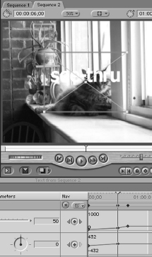
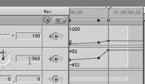
Figure 6-65 Correctly keyframed rotation parameter motion timeline
We still have one more keyframe, which will give one full rotation. This rotation will be aligned with the Scale keyframes that jump from 50 percent to 100 percent.
Since we have our keyframe at the third second, we need to add another at the fourth second so that our second full rotation completes as the scale reaches 100 percent.
STEP 66
Move the Motion Timeline playhead to the fourth second by entering “+100” and enter the value 360 into the Rotation field, which will rotate the text object fully once. When you add this value, the Rotation values should look like Figure 6-65.
Setting the Center parameter
The next parameter is perhaps the most important parameter for Motion work. It is the Center parameter, and how well you can use it over time really says a lot about how good you are at keyframing in general. Many parameters can be set almost by chance and still yield acceptable results, but the Center attribute and Motion Paths demand precision. The more time you spend working with clip positioning and keyframing, the better your motion paths will look. There is no substitute for practice.
Then again, the tools are easy and intuitive. Even the term “Center” itself simply means “where the central pixel of the clip is positioned on a given frame.” This is where the math comes in, because X and Y coordinates apply to everything in motion, and if you can shuffle the X and Y coordinates around well enough, you’ll be able to convince the viewer that you’ve been working with the Z, or depth, coordinate as well.
What is a Motion Path? A Motion Path is simply a trail of position values that change over a range of frames. When an object has a Motion Path, it has a new position value for each frame within the Motion Path. As the frames are played back, the object moves to the new position demanded by its Center keyframes. This movement over time is motion, and the line describing these changing position values over time that appears in the Canvas and Viewer when Wireframes are visible is called the Motion Path.
Intuition tells us that we’d want to set our first keyframe in the first place that the clip appears. But unfortunately intuition does not usually involve strategic thinking. In the present example, we know where the text will end up—right smack in the center of the screen at its present 0, 0 coordinates. Our text may zoom in from the left, right, up, or down, but it will end up in a specific place based on the design of the graphic.
STEP 67
Since we know that we want our text to end up in the center of the screen, advance the playhead to the third second, where our motion will stop, and click the keyframe button to create our first keyframe that has the default X and Y coordinates of 0 and 0, the center of the frame (Figure 6-66).
STEP 68
Once these values have been set into the keyframe, return the playhead to the first frame of the clip by typing “-300” and hitting Enter, or by hitting the left triangle next to the Keyframe button in either the Rotation or Scale parameters (Figure 6-67).
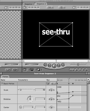
Figure 6-66
When setting position keyframes and Motion Paths, handling the clip manually in the Canvas window is usually the way to go, at least to get the keyframe quickly set in the neighborhood of the position you want to place the clip. You can more easily see the physical position of the clip as you drag and drop it, rather than trying to Figure out the X and Y coordinates of the new position.
![]()
STEP 69
Make sure that the Toolbar is set to the General Selection tool, return to the Canvas window, and click and drag the clip to the top, left-hand corner of the frame. If you refer back to the X and Y coordinates of the Center parameter in the Motion tab, they should be somewhere in the area of –300 and –150.
Since we might have to do mental math quickly at some point to adjust it again, choose a rounded value near the ones you have now and enter those values. For instance, if you got –291 and –142 from clicking and dragging, enter new round values of –300 and –150. Although these values are not substantially different in position, they will be much easier to work with if you need to figure pixel distances later. If the position must be exactly as you determined from the drag and drop, then leave the values you have.
A new Center keyframe will appear on the first frame of the clip as soon as you drop the clip the first time. If you didn’t get it right the first time, keep moving the clip until you get the desired position. The keyframe will change value every time you adjust the position. If you can’t get the X and Y values exactly right by manually dragging, you can simply type the X and Y values into the Center fields.
As you drag and drop the clip to create its second keyframe, you will notice that a small line appeared in the Viewer and Canvas windows between the initial keyframe at the third second and the next keyframe at the first frame of the clip. The thin line, which has many bumps along its length, is called the Motion Path. Each bump along the line is the position value for a frame in between the two keyframes. As we will see a little later, these bumps will tell us how fast the clip is moving and even how it speeds up or slows down.
A simple useful shortcut to remember when moving the clip manually with click and drag is how to constrain the movement to right angles. If you hold the Shift key down while clicking and dragging the clip in the Canvas or Viewer windows, the movement will be constrained to either horizontal or vertical straight lines. This is very convenient if you want to make sure your text doesn’t move diagonally at all. Simply set your first or final keyframe, move the playhead to the Timeline location of your next keyframe, hold the Shift key, click, and drag. You will see that the movement is possible only in vertical or horizontal directions.
After you have set the beginning keyframe for –300 and –150 and at the third second, the clip is positioned at the Center, your keyframing for the Center parameter should look like Figure 6-68.
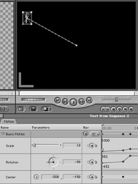
Figure 6-68 Correctly keyframed center parameter motion timeline
Looking at the initial motion
STEP 70
In the sequence Timeline, scrub through the frames and watch in the Canvas as the text clip now zooms up, spins 90 degrees, and moves from the top left corner to the center of the frame simultaneously over the first three seconds. Render the sequence, and play it back.
Sometimes, it is difficult to separate your eyes from the two-dimensional world of Final Cut Pro keyframes and see the faux Z dimension you are creating, but try to see how the combination of scale and size create a silent third value that perceptually equals depth. Also notice that at each frame you park the playhead on between the Center keyframes, the clip is centered on a bump on the Motion Path. As you scrub up the Timeline, the clip moves down the Motion Path.
After enabling the Clip Keyframes display button in the Timeline window, the area underneath the text clip will be occupied by a blue line. The blue line is an indicator that there has been a change in the default Motion tab settings for the clip in the track. The Clip Keyframe display bar will also reveal the existence of any Effects Filters applied to the clip with an additional green bar. Both of these indicators are valuable, particularly because after you render a clip, it may be difficult for you to remember that effects were applied to it. Knowing that effects were applied and then rendered (which you would know because of the absence of the red render bar) may one day keep you from accidentally unrendering a section of your work.
Setting the Anchor Point keyframes
The final parameter for the Basic Motion attribute is the Anchor Point. As we described earlier, the Anchor Point is not an obvious physical value. Changing the Anchor Point alone will not make the clip smaller or turn it upside down. The Anchor Point is rather a value that alters all other physical values. The Anchor Point determines the central point from which all other activities are performed.
This can be confusing, because changing the coordinates of the Anchor Point often has the opposite effect from the one you were hoping for. Successful use of the Anchor Point depends on abstract thinking and simple concrete logic. Just drawing out on a piece of paper what you intend to do makes it clear what settings you need. Above all, do not avoid the Anchor Point just because it is sometimes counterintuitive. Try this exercise, then watch television and start looking for examples of its use in animation.
For our example, we want the initial zoom out and rotation to proceed normally, as if the text were turning itself as it approaches the viewer. For this effect, the text will have an Anchor Point value of 0, 0 for X and Y respectively. This means that the axis of the rotation will be at the exact center of the text clip. The clip will spin like a wheel, with the text at the center.
STEP 71
Create the first keyframe for the Anchor Point at the first frame of the text clip with the default value of 0, 0. This keyframe should be lined up with the keyframes of the other parameters (Figure 6-69).
Until we give the parameter a new keyframe value elsewhere, the Anchor Point will remain in the X and Y center of the clip. But in our description of what we want to end up with, we proposed to have the text perform another quick rotation after reaching the end of the first zoom-out/rotation, this time with the rotation from a different axis in the clip. Now we will need to add more keyframes.
Since our first zoom/rotation ends and the next one begins at the third second, it would seem apparent that our new Anchor Point value to create the different rotational axis should occupy that keyframe. Unfortunately this is not so, but let’s make the mistake anyway and see why.
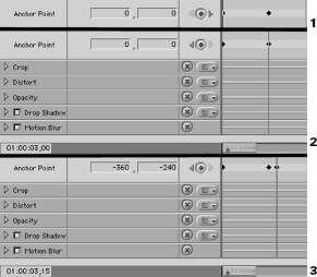
STEP 72
First make sure that your Canvas and Viewer windows are set to Image+Wireframe so that the Motion Path we will be affecting is shown. It may also be beneficial to lower the screen size of each window to 25 percent to aid in screen redraw times and to allow you to manually control Center parameter values if they should end up far off-screen.
STEP 73
Move the Motion Timeline playhead up to the third second. Enter new values –360 and –240 for X and Y for the Anchor Point keyframe (Figure 6-70).
When you enter this value, the physical position of the clip and the shape of its Motion Path will change drastically in the Canvas and Viewer windows, even though your Center position values have not. The clip appears to act as before for a scant few frames, and then begins to spin wildly in a circle long before it reaches the keyframes at the third second.
This is because the Center and Rotation values are now being figured based on having the center pixel of your text clip in the extreme upper left corner rather than in the center. When we set this new Anchor Point keyframe, we told Final Cut Pro that Center and Rotation values should be computed from there instead of the 0, 0 center of the clip.
To make matters worse, our new Anchor Point value is the second, not the first, keyframe value, so that the Anchor Point axis and position are changing over time. This makes it even more difficult for us to track and predict the motion path we are creating. Scrub through the frames and try to isolate the Anchor Point change as it occurs and observe the effect it gradually has on the rotation and position values.
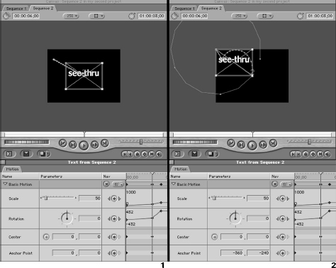
In the Wireframe view, the Anchor Point progression line, which obviously is changing positions between the two Anchor Point keyframes, can be distinguished from the Motion Path created by the two Center keyframes. The Motion Path always contains bumps that indicate the Center position of a given frame between two keyframes. The Anchor Point progression line is simply an unbroken line between the relative position of the Anchor Point in the first keyframe to its relative position in the second keyframe (Figure 6-71). This can be a little tricky to see, since the Anchor Point’s effect is to change the frame’s X and Y position on which the Center and Rotation values are based.
STEP 74
Position the Motion Timeline playhead at the first keyframe of the clip. Using the Left and Right Arrow keys, scroll through the first three seconds of the text clip and back to examine the behavior that is being created by simultaneously shifting the values of the Anchor Point and the Center and Rotation. Keep an eye on the Anchor Point’s shift from the center of the clip to the left top corner of the clip. Then observe how this results in the spiral of Center and Rotation as these parameters also change based on their own keyframes.
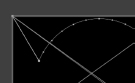
Now, the effect we really wanted was to have the text clip first rotate and zoom based on an axis at the center of the text clip. Then after the clip reached the three-second point, we wanted it to perform another rotation, this time rotating from its top left corner rather than from the center axis. What happened instead is that we gave the parameter one keyframe too few. In order to perform what we are describing here, the Anchor Point value needs to remain the same all the way until the third second, and then change positions to the new value.
With only two keyframes as we have it now, the parameter values interpolate between the first frame and the third second; as a result, the axis slowly shifts over the length of the clip. This results in a spiral as the Rotation and Center values shift consistently with the Anchor Point. We need another keyframe positioned at the third second to keep the Anchor Point keyframe value at 0, 0 up until that point.
Just after the three-second point, we want the Anchor Point to change to the top left-hand corner at –360, –240 so that the rotation occurring between second three and second four will use the new axis for the rotation. To make this change in Anchor Point a little more natural, we will keyframe it so that the Anchor Point shifts over time.
STEP 75
To make sure that you have these keyframes set appropriately, make sure the values and timing match the following:
The first frame of the clip should have an Anchor Point keyframe value of 0, 0. |
|
The third second of the clip should have a keyframe value of 0, 0. |
|
One half second later (15 frames for NTSC and 12 frames for PAL), there should be a third keyframe value of –360, –240. These keyframes should look like Figure 6-72. |
STEP 76
Scrub through the clip on the Timeline window using the Left and Right Arrow keys, and observe the different effect of our new Anchor Point keyframes.
Right up to the third second, the rotation spins obediently in its quarter-turn using the 0, 0 as the Anchor Point axis. But as soon as it hits the keyframe at the third second, it encounters an interpolation of Anchor Point X and Y coordinate values covering one half second.
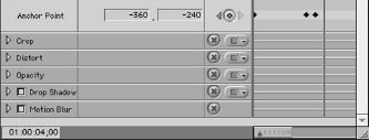
Figure 6-72 Correctly keyframed anchor point parameter motion timeline
It begins the second rotation, but does so as the rotational axis is shifting. By the time the rotation is complete, so is the axis shift. The end result, as you will see, is that when the clip appears far away, its rotation appears to be centered on its own axis. But as it approaches the viewer, it appears to gradually shift into an interesting spiraling change in rotational axis from center to extreme corner.
This little performance could have been keyframed entirely from within the Rotation and Center parameters, but it would have taken an enormous amount of tweaking and mathematical work to get the keyframes positioned and coordinated. Instead, our Anchor Point adjustment required only three keyframes. Clearly, this tool can be useful in creating complicated motion paths and rotations with far fewer critical Center and Rotation keyframes. Learn to use the Anchor Point, and it will save you hours of work one day.
Setting the Distort attribute
The next attribute we will set is Distort. Technically, there is no need for the Distort attribute here, but we want to take advantage of its power to shape our text so that it also appears to unfold from facing up to facing forward in its initial rotation. We will also use it to add a slight distortion curve to the text itself so that it appears to have some depth.
We will set the first four parameters first, these being the X and Y coordinates that determine the position for each corner of the clip. Remember that the values for these coordinates are based only on the clip itself, not its sequence. As we will see, changing the X and/or the Y value will merely stretch the clip to compensate. Stretching it beyond the limits of the clip’s frame would result in part of the clip becoming masked in the Canvas window, just as our text clip was when its Font Size setting was too large to fit in the window.
Setting the Distort parameters, like setting the Center parameter, is a job that is best initially handled by visual spec in the Canvas or Viewer window. There is a special tool for Distort effects within the Video windows.
To access the Distort tool, go to the Toolbar and select the second toolset from the bottom (Figure 6-73).
This toolset contains the Crop and Distort tools. The Crop and Distort tools set values for the like-named attributes within the clip, based on the parameters as discussed above. Although we will not be adjusting the Crop parameter, its keyframing and adjustment are similar in form to the Distort we will work with.
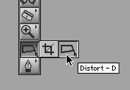
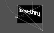
STEP 78
Select the Distort tool and move to the Canvas window. We do not need to set any initial keyframes for the first four parameters, because the values assigned to them will remain constant throughout the animation. Move the Motion Timeline playhead up to the fourth second, where the Scale keyframe is set to 100 percent, making it much easier to visually spec as we adjust.
Since we are directly adjusting the shape of the clip using the Canvas window’s Wireframe, having the clip scaled up to 100 percent will facilitate the operation.
STEP 79
Make sure that the window is set to Image+Wireframe, and then use the Distort mouse pointer to grab the bottom left-hand corner and move it up to around a quarter from the bottom and the extreme left-hand side of the frame. Then grab the bottom right-hand corner of the clip and drag it down about an equal amount outside the boundaries of the frame, but vertically aligned with the right edge of the frame (Figure 6-74).
The effect of these two adjustments will result in a pinched left-hand side of the text and a stretched right-hand side.
STEP 80
If you cannot get the Distort tool to perform this properly, simply enter the following coordinates for these two parameters: Lower Right 360, 440, and Lower Left –360, 100. Leave the upper two parameters, Upper Left and Upper Right, and the Aspect Ratio intact.
Earlier in the text, we set Opacity using the Pen tool in the sequence Timeline, but we can just as easily do it here. The keyframing we do for Opacity will have the same effect on the clip that it did from the sequence Timeline. In fact, any keyframing you do at the sequence window appears here. In addition, any keyframes you enter here will appear on the sequence Timeline if you have the Clip Overlay button enabled there.
Rubberbanding on the sequence Timeline is just a quick shortcut for the Opacity parameter. But when you are trying to coordinate many different visual effects into one grand motion, being able to line up keyframes is essential. Therefore, it’s usually best to set Opacity keyframes within the Motion tab whenever you want to group changes in visibility with other Motion properties.
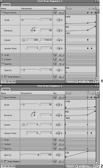
Since our text clip is supposedly far in the distance at the beginning of the animation, it stands to reason that its Opacity should be dramatically lower.
STEP 81
Return the playhead to the beginning of the clip, create a new keyframe for Opacity and enter its value as 10 percent (Figure 6-75).
We don’t want to start the clip as completely transparent, because initially our clip does not start out infinitely small. Part of the believability of this animation is that it looks real. From the viewer’s perspective, the video frame does not extend into infinity, and starting from an infinitely small and dark setting would suggest that it does. Straining believability is not a good idea when performing sleight of hand; ask any magician. Therefore, our clip will appear very small and semi-opaque at first, but with definite substance, rather than as a pin prick on the horizon.
STEP 82
After you have set the first Opacity keyframe, advance to the third second. At that point, the clip will be in full visual range, and there will be no further reason to attempt to hide it. Enter a value of 100 percent (Figure 6-75). This keyframe will bring the clip up to full visibility.
If you Left and Right Arrow scrub through the clip on the sequence Timeline, you will see the accentuation that change in Opacity gives the clip as it is changed by the other attributes.
Setting the Drop Shadow attribute
Next we will set a drop shadow for the text clip. We will be keyframing the change in the drop shadow so that it appears that a real stationary sun to the left of the screen is causing it. We will start with the three-second mark as our principal shadow, and then keyframe the changes from there.
STEP 83
Click in the checkbox to enable the Drop Shadow attribute, and then move the Motion Timeline playhead up to the third second (Figure 6-76).
STEP 84
At the three-second mark, insert an initial Offset parameter keyframe value of 3. Offset is the distance between the object and its drop shadow. At the three-second mark, an Offset of 3 should look pretty nice. The problem of course is that when the Scale changes, the Offset needs to change values as well, since when the text is further away and smaller, its shadow will also appear smaller.
Move the playhead to the beginning mark and enter a new keyframe value of 1. Now as you step forward through the frames from the beginning of the clip, you should see the shadow hug the text a little more tightly.
The Angle parameter is especially important if our shadow is to look like it was cast by another object. Since the drop shadow is actually projected from the clip and not a stationary light, we need to keyframe the shadow’s changing position in relation to the imaginary light. Doing so is easy. The area of real importance for the drop shadow is the giant rotation at the end of the animation.
Our initial shadow angle will be set for a light in the top left-hand corner.
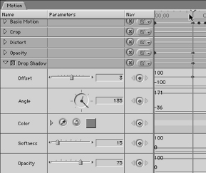
STEP 86
Create and set the initial keyframe for the Angle parameter at the beginning of the clip at 145 degrees.
STEP 87
Advance the Motion Timeline playhead to the third second. This is where our text begins a large rotation and where we need to correct the Angle keyframes so that the shadow appears to remain stationary.
STEP 88
Add a new Angle keyframe that maintains the value 145 at the third second (Figure 6-77). This second keyframe exists solely to keep the Drop Shadow Angle value of the first three seconds locked in at 145 degrees. The next keyframe will actually cause the rotation of the Drop Shadow Angle in the opposite direction of the clip’s rotation, which from the viewer’s perspective means that the light casting the shadow is stationary.
Advance to the fourth second and enter a new Angle keyframe value of –215 (Figure 6-78). The importance of entering your values numerically here is supreme. It is easy to accidentally turn the Angle wheel in the wrong direction, resulting in a sun that reels across the imaginary sky while your text reels about the frame.
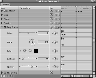
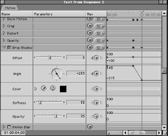
Negative 360 degrees equals one counterclockwise turn. Since our text is turning clockwise and we want our shadow to remain in the same direction it was, our shadow angle should turn the exact same amount of rotation but in the reverse direction. This will cancel the travel of the shadow, leaving its imaginary light source appearing to be in the same position.
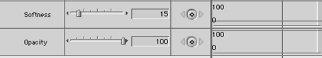
STEP 90
The primary reason for the drop shadow is to accentuate our text, so enter a low value for Softness of 15 and a high value for the drop shadow’s opacity of 100 (Figure 6-79). Since these values will remain consistent for the entire animation, there is no reason to keyframe them.
Applying nonlinear interpolation techniques
Render the animation, and take a quick look at it as it plays back in real time. You may be surprised to see that, despite all our precise settings, something still looks slightly unnatural about the movement. There’s nothing wrong with the settings, except that we haven’t gone quite far enough with them. Before going further, we have to explore the idea of linear versus nonlinear interpolation.
All the keyframes we have applied so far have used linear interpolation: when the value changes between one keyframe and the next, the change in value is evenly spread over the frames in between the keyframes. For example, if at frame 1 there is a keyframe whose value is 1 and at frame 10 there is a keyframe whose value is 10, at frame 2 the value will be 2, frame 3 the value will be 3, and so on. Although there are no keyframes between frames 1 and 10, Final Cut Pro evenly interpolates the exact value for the frames in between.
When it interpolates those values, the process is called linear, because there is no variation in the rate of the value’s change. But we know that the real world does not operate along such rigid lines. Not even a robot could begin moving at exactly ten miles an hour, travel an entire distance at the same speed, then stop on a dime. In the real world actions start slowly, speed up, slow down and stop, and not necessarily in that order.
So Final Cut Pro allows you to perform what is called nonlinear interpolation. This means that between two keyframes, there can be variations in the values between the keyframes. For instance, between frames 1 and 10 of the above example, frame 5 could have a value of –5, or 20, or anything else, as long as it gets back to 10 on the tenth frame.
Of course the values that come into play for nonlinear interpolation depend on the attribute or parameter involved. This nonlinear interpolation of keyframes is divided into two types: Ease In/Ease Out, which is the method for Motion Paths, and Smooth, which is the method for everything else. Ease In/Ease-Out allows us to vary the speed of a moving clip across the frame, slowing down and speeding up between keyframes. Smooth allows us to introduce curves into the interpolation of attributes and parameters such as Scale, Rotation, and other keyframeable effects.
Adjusting the motion path using Ease In/Ease Out
STEP 91
To set Ease In/Ease Out for the Motion Path, select the text clip on the sequence. Move the Motion Timeline playhead to the first frame. Make sure your mouse pointer is set to the General Selection tool. In the Canvas window, change your view mode from Image+Wire-frame to Wireframe (Figure 6-80).
Ease In/Ease Out must be set on the Motion Path of the object itself in the Canvas or Viewer window, and it is much easier to see this in Wireframe mode in which the clip’s imagery is not visually distracting.
STEP 92
Once in Wireframe mode, you will see your text clip’s Wireframe in the top left-hand corner. If you move the mouse pointer over the Center of the clip, the pointer will change into a crosshair. When it does so, Control-click, and you will receive a contextual menu with the options Make Corner Point, Ease In/Ease Out, and Linear (Figure 6-81).
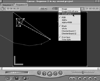
The interpolation is presently Linear; select Ease In/Ease Out on the contextual menu to change this to nonlinear interpolation.
When you do so, you will see two new points appear, a small one and a large one (Figure 6-82). You may need to zoom in on the Motion Path to see the points, since they look similar to the Motion Path’s frame bumps, but slightly larger in size. These are referred to as Bezier handles, and they allow you to adjust the Motion Path of your clip based on a direct manipulation of the curves created by tugging on the Bezier handles themselves.
Of the two, the larger handle is for creating curved shapes in the Motion Path. Grabbing either of the two larger Bezier handles drags the formerly straight Motion Path out along a curved path. Although it’s difficult to be entirely precise using this tool, it can be a quick way to create smooth, curved motion when you need it.
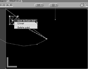
Grab the end of the larger Bezier handle and drag it slightly up so that you introduce a gentle curve to the first leg of the Motion Path that looks like Figure 6-83.
The Motion Path has been slightly altered by the Bezier handle so that the path of the text clip curves somewhat as it moves to the center of the frame.
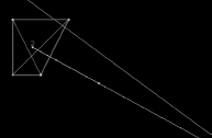
STEP 94
Float the crosshair mouse pointer above the smaller bump on the Bezier handle and drag in either direction along the handle (Figure 6-84). Unlike the larger Bezier bump at the end of the handle, it will not create a curve in the Motion Path and its adjustment is restricted to the distance between frame bumps inside the present Motion Path line. As you drag the handle, the many other smaller frame bumps on the Motion Path become closer together or farther apart.
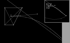
This is the essence of speed change, or velocity. Each small bump on the Motion Path indicates the position of the clip during that particular frame. Each bump is a position in time as well as the X and Y coordinates of its position in space. As you tug on the Ease In/ Ease Out Bezier handle, the bumps get further apart or closer together, meaning that the clip will move a further or shorter distance between the two bumps or frames. When two bumps are very close together, it means that the clip is moving very slowly, because it is only traveling the small distance between the bumps over a single frame. When the bumps are far apart, the clip is traveling very fast, because it is covering far more distance between the frames.
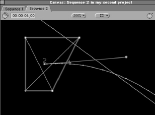
Float the mouse pointer over the smaller Bezier handle. When it changes to a crosshair, click and drag the small handle toward the center of the clip. This will cause the frame bumps to be much closer together near the beginning of the Motion Path and further apart near the three-second mark where the second Center keyframe is located.
Thus, the clip will appear to move slowly at first as it grows in size and then it will speed up slightly as it approaches 100 percent Scale. Using your imagination, you can make fast-moving clips rush to a stop, start up slowly, speed up, and slow down naturally or whatever other combinations of Ease In/Ease Out you can think of. The key is to look at the material and the Motion Path and decide what looks natural.
It should be noted that the Ease In/Ease Out nonlinear interpolation is far from extreme in its adjustment of velocity. While you can change velocity, as we have just done, the change will be gentle. The purpose in Final Cut Pro is to smooth out the motion of clips moving along Motion Paths, particularly as they move around corners. Other applications such as Adobe After Effects and Pinnacle System’s Commotion have far more comprehensive and intuitive tools for this sort of nonlinear interpolation. If you really want to get into realistic inertia-affected motion, you might consider looking into one of these animation packages. The theory of motion and keyframing is the same, but the tools are more robust.
Adjusting the other attributes and parameters using smooth curves
We can also adjust the other attributes by using Smooth curves in the Motion Timeline. Nearly all attributes and parameters that have interpolated keyframeable values can be treated with nonlinear interpolated Smooth curves. If there is an interpolated value line between two keyframes in the Motion Timeline, Control-clicking one or both of the keyframes will allow you to apply Bezier handles to them, giving you control over the rate of the change in value occurring between the keyframes.
A direct and clear example of the power of Smooth curves with Bezier handles can be seen by adjusting the Rotation attribute of our text clip.
STEP 97
Go to the Motion Timeline, scroll up to the Rotation attribute, then resize the scale of the Timeline such that you are looking at all three keyframes of the parameter.
STEP 98
Float the mouse pointer over the middle keyframe located at the third second. When you do this, the mouse pointer will turn into a crosshair, indicating that it is ready to adjust a keyframe.
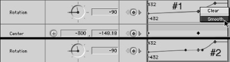
Control-click the keyframe, and hold the mouse button to receive a contextual menu offering two choices: Clear and Smooth. Select Smooth and release the mouse button (Figure 6-85).
Once you release, the keyframe should sprout two blue Bezier handles pointing in either direction from the keyframe. These two handles are linked to produce an equal and opposite curve when adjusted; if you drag up and out with one handle, the handle on the other side of the keyframe will move down and out to produce a smooth curve from the keyframe preceding it to the keyframe following it. If there is no keyframe preceding or following the keyframe that has been set to Smooth, it will show only one or no Bezier handles, since one or zero keyframes on a timeline imply no change in value and Bezier handles exist only because there is a change in value.
STEP 100
Grab the left-hand Bezier handle and drag down and out to produce a curve shaped like a trough (Figure 6-86).
STEP 101
Now move the playhead to the beginning of the timeline, make sure that your viewing mode is set to either Wireframe or Image+Wireframe, and frame scrub (depress Right Arrow key) through the interpolation. Keep an eye on the actual rotation in the Canvas window and match it to the changing values in the numerical field in the Rotation attribute line of the Motion tab.
As you frame advance through the clip, you will notice that the rotation value in the numerical field far exceeds the initial keyframe’s value of –90, resulting briefly in rotation in the wrong direction! But the clip still ends up at a value of 0 by the time it makes it to the Smoothed second keyframe. Remember that negative rotation values simply mean rotation in the counterclockwise direction, so making the trough deeper simply forces the rotation even further in the counterclockwise direction before sending it back to a value of 0.
![]()
Also notice the smooth gradual change in rotational angle values as you frame advance both visually in the Canvas and numerically in the attribute field. Visually, the rotation slows down as it reaches the bottom of the trough, then speeds up as it returns back in the direction it came from, ascending the second curve of the trough. Also notice that in the numerical field, the angular values for the interpolation are expressed to two decimal points. Both linear and nonlinear interpolation are this accurate, far more accurate and speedy than the average editor would be in figuring out the curve manually. This accuracy is most valuable in determining the curve values for this and other attributes and parameters. Since curves are mathematically determined, it’s easy for Final Cut Pro to crunch the numbers for a nice smooth curve value that looks very natural.
One feature that may seem problematic is the fact that adjusting a Bezier handle in one direction automatically adjusts the handle in the other direction as well. That may be fine in many situations where the value change should be smoothed along the entire timeline. But what if we want to set a curve for only one side of the keyframe, leaving the other interpolation intact? There are two options available.
STEP 102
The first is to Command-click the Bezier handle you want to adjust (Figure 6-87). When you do so and drag the handle out, you will see that this does increase the extremity of the other side’s interpolation without affecting its curvature. Performing this on the right-hand Bezier handle of our example text clip will show the left-hand trough increasing or decreasing in depth as you adjust, but only relative to the change in the right-hand Bezier handle. The shape of the trough is the same, but the values become more or less extreme relative to the amount of drag you create on the right-hand side.
STEP 103
While that can be valuable, many times the Bezier handles must be adjusted completely independently. To accomplish this, Shift-Command-click either handle and adjust its curve to your satisfaction. Using the Shift-Command click, straighten the interpolation between the first and second frame, but now Shift-Command-click the right handle and create a curve for the rotation between keyframes two and three. This will cause the rotation at the beginning of the second keyframe to occur more quickly and give the appearance that the right edge of the text clip is leading the spin.
Your Rotation keyframes should look like Figure 6-88 when set correctly.
Render your timeline and take a look at the effect this has on the rotation in real-time motion. Also go in and experiment with other attributes and parameters that offer nonlinear interpolation through Smooth keyframing. You’ll quickly learn how to exploit curves for smooth natural effects.
![]()
The final attribute to be set for the text clip has been left to the last for good reason. Motion blur, as described earlier, is a very processor-intensive operation that slows down rendering enormously. While certainly worth it for the realism it affords motion, the slowdown in processing a single frame can really cramp your style when you are busy setting complicated motion keyframes in place. As such, it should generally be disabled until you are ready to use it.
![]()
Figure 6-88 Correctly keyframed rotation parameter motion timeline
Unlike other attributes, motion blur is not keyframeable. Motion blur is a constant effect that you set into place. It’s somewhat similar to the physical phenomenon of gravity. Although gravity causes the weight of an object and gravitational pull is the same for all objects, not all objects weigh the same amount. Motion blur is the same for the entire clip, but its actual visual effect depends on what the frames being blended by the Blur are doing at any given time. Fast movement will equal much motion blur; slow or no movement will result in little or no motion blur.
The key is to make sure that you aren’t setting the percentage, or number of previous and future frames included in the blur, too high or low. If the motion is only 30 frames in length, 500 percent motion blur will likely be too high a percentage.
STEP 104
Enable Motion Blur for the clip by clicking in the checkbox for the attribute. Since our motion is very short and very fast, set the percentage to 100, so that it is blending only the frame prior and frame following (Figure 6-89).
STEP 105
Set the Samples to 8, which will result in a rather smooth blend between the blurred frames, but won’t take an eternity to render.
STEP 106
Return to the Canvas window, park the playhead somewhere within an area of movement and you should see a nice blur. The blur should not be so extreme as to make the text completely unreadable, but should suggest motion, even on a parked frame.
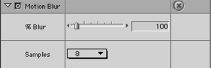
Render the sequence once again and observe the blur in action. Depending on factors such as the size of your text clip, the keyframing you’ve set and the values for motion blur, your results may vary slightly. Experiment with the settings and you will arrive at the perfect setting for the clip you are working with.
Speed and duration
Another effect that you can apply to video and audio clips is Speed. It is easy to change the speed of a clip directly. Because of the flexibility of the Speed control dialog box, it’s also easy to coordinate the new speed with a specific duration so that you can slow the clip down to match another element in your sequence.
To change the speed of a clip, we want to load it into a sequence first. Although you can change the speed of a clip by simply selecting it in the Browser or loading it into the Viewer, this will actually apply the speed change to the original clip, which is more than likely your Master clip. Clips that have had their speed adjusted must be rendered to play back correctly, and rendering can only occur in a sequence.
STEP 107
Edit a clip into a fresh empty sequence. Adjust the Time Scale of the sequence so that the entire clip is visible on the sequence timeline.
STEP 108
With the clip selected, go to the Modify drop-down menu and select Speed (Figure 6-90). When you do so, you will receive a dialog box that allows you to customize the resulting clip generated by the Speed command.
The first field is for percentage. 100 percent, the default, is normal speed. Lowering the percentage will decrease the speed; raising it will increase the speed. Below this is a Duration field. Notice that if you hit the Tab key after entering a new value into the Speed field, the Duration field updates, revealing the new duration of the clip. Reducing speed to 50 percent will result in the duration doubling, while doubling the speed to 200 percent will result in halving of the duration.
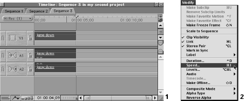
STEP 109
Type 50 percent into the Speed field, and watch the Duration field double in length (Figure 6-91).
By the same token, changing the Duration field will give a new speed percentage value. This is probably the most valuable tool for wily B-Roll video editors who want to make the most of every frame they have, and who aren’t afraid of adjusting the speed of a clip to make it fit just right into its edit slot. Although Fit to Fill, one of the Canvas’ editing overlay boxes, also performs this function automatically, you can’t specify the speed change before committing to the edit. With the Speed command, you enter the space you have for the clip, and you can immediately see the speed change your clip will be subject to when processed before committing to it.
The Reverse checkbox simply applies a negative value to the percentage. This means that in addition to any speed changes made, Final Cut Pro will also reverse the order of the frames in the clip, making it run backwards.
Frame Blending should always be enabled. When you speed up or slow down a clip, you are removing or creating frames of video to make the video appear faster or slower. This can cause strobing or stuttering if the new set of frames do not appear to be as continuous or sequential as the original set were. Frame Blending creates new intermediary frames that are a blend of the two new frames left over from the speed change. The result is smoother and cleaner speed changes.
STEP 110
Enable Frame Blending, leave Reverse disabled, and hit OK. The clip in the sequence will have doubled in length and require rendering. If you render, you will observe the very smooth slow motion.
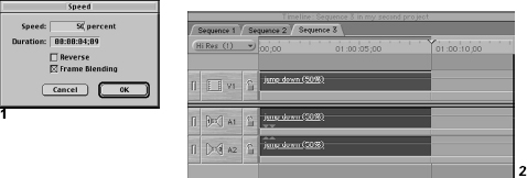
Bear in mind that any change in speed will require a render, since no video media file yet exists for the speed-changed clip. Interestingly, if you change the speed and then change it back to 100 percent or normal, the speed change will not require rendering, since the second speed change simply refers the clip back to the original clip media. When you change the speed, the clip in the sequence will be marked with the percentage of the speed as a handy reminder that the clip is modified.
Effects filters
What are effects filters?
You can also apply effects to a clip that are based on the use of filters, otherwise known as plug-ins. In reality, filters are special scripts that are applied to clips to produce specific effects. Rather than adjusting one physical element of a clip at a time, filters usually change many different aspects of a clip at once. Instead of being designed to change the raw physical attributes of a single clip, filters usually change several at once to produce a desired effect.
The effects filters can be applied in a manner similar to the application of the Transition. You can simply drag and drop the effect from the Effects tab of the Browser window onto the clip, or you could apply the filter by selecting the clip and accessing the filter from the Effects drop-down menu. In this example, we will use the latter process although there is no functional difference between the two. Use whichever seems more effective in your personal workflow.
Applying a color effect; the invert filter
Let’s apply a couple of effects filters of varying sorts to see how they affect the clip.
STEP 111
Edit a fresh clip into the sequence and double-click it to load it into the Viewer window. As with the Motion tab settings, we will be able to see our work update in the Canvas window, but the Filter parameters and their keyframes themselves must be set in the Filters tab of the Viewer window.
STEP 112
Once the clip is loaded into the Viewer window, click on the Filters tab to bring it to the front.
STEP 113
Go to the Effects drop-down window, select the Video Filters submenu, and then select Channel and Invert (Figure 6-92).
Your clip should immediately and radically change in the Viewer and Canvas windows. The Invert filter works its visual magic by changing the values of chroma, luma, and alpha equally and opposite within a clip. Whites become blacks, yellows becomes blues, all colors invert based on their opposites in the RGB color wheel. But you are not limited to this default appearance. By adjusting the parameters of the Invert filter, you can choose exactly which chroma, luma, or alpha channels are inverted, as well as the extent to which they are inverted.
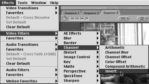
STEP 114
Go to the Filters tab in the Viewer window, and tear it away (Figure 6-93). We want to be able to watch our effect change in the Viewer Video window as we adjust the parameters of the filter. If you tear the tab away and find no Invert filter present in the tab, you have either misapplied the filter to the wrong clip, or you have loaded the wrong clip to the Viewer window.
For a standard captured clip in Final Cut Pro, the filter tab will have two sections: a Video Filters section and an Audio Filters section. Any filters applied to the clip will appear here. If there are no audio clips linked to the video, there will be no section for audio clips on the filters tab. The reverse is also true for audio-only clips such as imported audio CD tracks.
After applying the Invert filter, you should see the Invert filter in the Video section of the Filters tab. There is a checkbox for enabling and disabling the filter. This can be very handy if you’ve worked hard to get the settings for a filter correct, but you need to make it disappear for a moment. Rather than deleting the filter by selecting its name and clicking Delete, you can simply turn it off at the checkbox and then re-enable it when you are ready for it again. Be warned that disabling the filter with the checkbox removes any render files associated with it, so you’ll have to re-render if you do so.
In the parameters for the Invert filter, there is a drop-down bar allowing you to choose the image data that you want to invert. You can choose from many arrangements that will have different effects. Even though you know that the actual frames of DV are digital RGB images, you can invert based on luma (or Y), any of the specific RGB channels individually, an alpha channel if present, or UV. For the moment, leave this set to the default RGB (Figure 6-94).
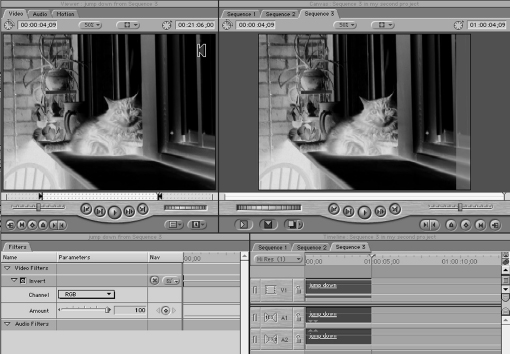
The other parameter you can alter is the Amount. This parameter is a percentage based on the degree to which pixel values are inverted. A value of 100 percent means that pixels are completely inverted, and 0 means they are not inverted at all (Figure 6-95).
STEP 115
To illustrate the idea, type 50 into the Amount field and hit Enter to apply the change. The screen should be completely gray, since all pixels are being inverted exactly halfway to the opposite. The halfway value for any inverted color is always exactly middle gray. Type in the value 100 again to return to the full Invert.
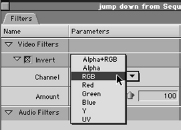
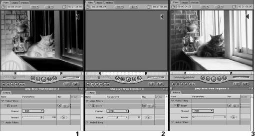
You will see that this parameter is keyframeable, as are many parameters in most Effects Filters. The keyframing lesson of the previous section applies to this keyframing, and most parameters can be adjusted with Smooth curves as well.
Applying an effects filter matte; the garbage matte
STEP 116
Make sure the Viewer window with the Filters tab is active, and go to the Effects dropdown menu (Figure 6-96). Select the Video Filters submenu, then Matte and, finally, Four-Point Garbage Matte.
When we discussed matting in the section on Composite Modes, we talked about using luma values or alpha channels to create transparency mattes, or areas of an image that you could see through to the next layer. The approach there was to block or allow transparency in the frame using the luma or alpha values of another layer as a mask. With the garbage matte, though, we can create areas of transparency from directly within the clip itself.
The garbage matte is exactly what its name implies. It is used to matte garbage that you don’t want seen out of the frame. But instead of building complex alpha channels or being constrained to an exact rectangle or square, as the Crop tool would require, you can arbitrarily set the positions of the four corner points of the matte. If the shape you need to matte is more complex than is possible to matte with four points, an Eight-Point Garbage Matte is also available in the same Effects filters Matte submenu.
We’re going to make an interesting framing effect using the inverted colors and the garbage matte to focus attention on one area of the frame.
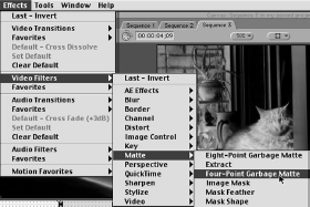
STEP 117
Move the clip with the Invert and Four-Point Garbage Matte filters up to the Video 2 layer (Figure 6-97).
STEP 118
Set the target track to the Video 1 layer, and then line up the sequence playhead with the first frame of the clip in the Video 2 layer.
STEP 119
Now, select the Video 2 layer clip and copy it, using Command-C. Hit Command-V for Paste. Paste will make an exact copy of the Video 2 layer clip in the Video 1 layer, using the playhead as the insertion point. Alternatively, hold the Option and Shift keys down, and then move the clip back to the Video 1 layer (Figure 6-98). Final Cut Pro will automatically Copy and Paste it there for you.
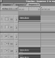
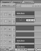
You now have two copies of the exact same clip lined up frame for frame, one above the other. We will remove the Invert and Garbage Matte filters from the bottom background clip. Copying and Pasting will have included the filters, but they are necessary only in the Video 2 layer clip.
STEP 120
Double-click the Video 1 layer clip, and bring it up into the Viewer window. Select the Filters tab, then select and delete each of the two filters by clicking on the name and hitting the Delete key. Make sure that you are deleting the filters from the Video 1 layer clip and not the Video 2 layer clip.
STEP 121
If you hit the Track Visibility Green Light in the sequence to turn off the Video 2 layer, you should see that you now have a background clip that exactly mirrors the clip above it with the exception of the Effects filters applied to the latter (Figure 6-99). Turn the Video 2 layer track visibility back on, and you should see the layer we are going to use our garbage matte on.
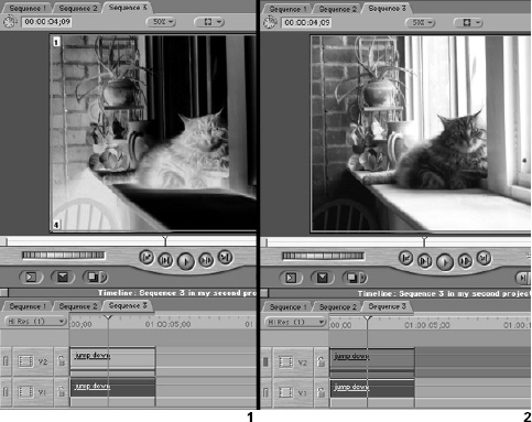
Let’s set the parameters for the garbage matte.
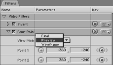
STEP 122
Double-click the Video 2 layer clip so that it loads up into the Viewer window. Pull the Filters tab away from the Viewer window so that you can watch each window update as you work.
The first parameter on the Garbage Matte filter is the View Mode. Your choices are Final, Preview, and Wireframe (Figure 6-100). Each mode has its benefits. The Final view allows you to see the matte as it stands by itself. The matted out areas will appear as transparent, just as the image will appear in the Canvas above the background layer. The Preview mode gives the same view but also includes small numbers indicating the positions of the corners of the matte you will assign in the following parameters, making it easier to tell which corner needs to be adjusted for the desired effect. The Wireframe mode shows no transparency and displays a Wireframe shape representing the present shape of the matte. This mode allows you to set the positions while looking at the entire image. For our example, set the mode to Preview.
Underneath the View Mode are four point assignment parameters that correspond to the four corners of the matte. When the View Mode is set to Preview, the four points are identified in the Video tab of the Viewer window. You can enter precise X, Y position data into the fields for each point, but you can more easily set the positions by clicking the Crosshair button and then clicking a position in the Video window of the Video tab of the Viewer window.
STEP 123
Click the Crosshair button for Point 1, and move the mouse pointer to the Viewer window (Figure 6-101). The pointer will convert to the crosshair. Click on a position that you want to establish as the top left corner of the matte. You will see that the matte closes in and the Point 1 corner now occupies that position. In the Canvas window, you will see the matte taking shape.
Follow the same process for each of the other three points until you have created a four-cornered matte that crops the clip, revealing only the section that you want to reveal. Remember that the Four- and Eight-Point Garbage Mattes are valuable because they do not have to follow a rectangular or square shape like the Crop tool in the toolbar, so you can get a little wild with the shape (Figure 6-102).
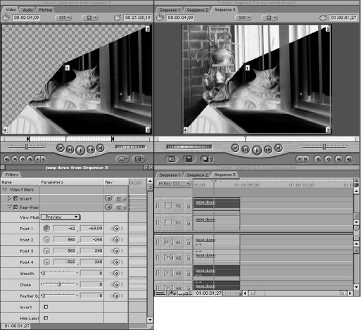
Be careful that you don’t overlap the lines of the matte, because the garbage matte is a geometric entity. It can create transparency only between the points. If you cross the matte lines, you will end up with unpredictable results.
The next parameter is for Smoothing the corners of the matte. There is no Bezier control of the corner points, so to soften them, you need to adjust this parameter. Unfortunately, you cannot apply a different corner softening effect for each corner; garbage mattes are rarely used for very tight matting operations but are useful for quickly eliminating material from the frame.
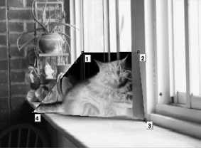
STEP 125
Set the Smooth value to 40 to get a nice round edge to the matte (Figure 6-103). The next parameter is for Choke, which shrinks the matte based on the value chosen. Choke is often misunderstood to refer to the choking of the image you see. Choke really refers to the invisible matte you are creating. Positive values of Choke will choke (i.e., reduce) the matte size, revealing more of the clip. Negative Choke values will increase the size of the matte, hiding more of the clip. It may seem pointless to set a Choke value when you could easily have just set the matte position correctly, but remember that this parameter is keyframeable. Since the Choke value expands or shrinks the matte size equally for all four points, Choke can be an easy way to adjust the size of the matte without having to keyframe four corner points individually.
The next parameter is Feather Edges. This parameter we have encountered before; it simply adds a gradient transparency edge to the matte so that the edge appears to fade into the background.
STEP 126
Give the Feather Edge parameter a value of 20 to create a wide fade between the inverted foreground and normal background clips.
The following two parameters are checkboxes for Invert, which just reverses which side of the matte causes the transparency, and Hide Labels, which causes the Point numbers to disappear from the Viewer window when in Preview mode.
Take a look back at the Canvas window now, and you will see that the Garbage Matte isolates the small section of the top inverted clip and the edge of the clip fades off into the normal uninverted background clip. The effects must be rendered to play back correctly, and you can always go back in and change the matte’s parameters. If you find that four points are not enough to create the complex matte shapes you need, the Eight-Point Garbage Matte doubles the number of corner points available for the matte. If you still find this too limiting, then you have promise as a compositor. You have stretched Final Cut Pro’s rotoscoping abilities to the limit and may want to look into a more robust 2D animation application such as Pinnacle Commotion or Adobe After Effects.
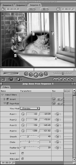
This is only an example of two of the many effects that come bundled with the Final Cut Pro nonlinear editor. A full discussion and demonstration of each Filter is far beyond the scope of this book. You have the tools to master the Effects filter interface and its keyframing convention. Experimentation, as well as referring to the descriptions of the Filters contained in the Final Cut Pro manual, is the key to mastering them all.
Nesting
Up to this point, we have only discussed effects work with regards to single individual clips. This is fine, but of course situations will arise where you need to apply the same Effects filters equally to all the individual clips in a sequence. Or perhaps after completing an edit of a sequence, you want to apply Motion tab–type effects to a sequence in its entirety rather than its individual constituent clips. This would be impossible to do with the sequence’s clips on a one-to-one basis.
The answer lies in Nesting. Nesting simply refers to placing a sequence inside another sequence so that the first sequence is treated as a clip. You can manually move one sequence into another by simply dragging and dropping it just like you edit in a clip. You can load a sequence from the Browser window into the Viewer window just as if it were a clip and then edit it into another sequence. And you can apply effects to a “clip” sequence as if it were a clip. About the only thing you can’t do with nesting is to nest a sequence inside of itself.
There is another benefit to Nesting that is less obvious. It can retain your render files, even in editing situations where ordinarily the render files would have been thrown out. Whenever you render, Final Cut Pro creates render files for the clip in the Render Folder of the Scratch Disk. It organizes these files according to the sequence where the rendered clips are in use. When a rendered clip is played back, Final Cut Pro goes into the Render folder and finds the clip based on which sequence it was rendered in. That’s why if you render a clip in one sequence and then copy it onto another one, it has to be rendered again. The sequence you copy it into has no render file associated with it.
To examine this, take a look at the Render Manager. The Render Manager is a special tool that allows you to eliminate old render files from your disk to free up drive space. To get to this tool, go to the Tools drop-down menu and select Render Manager (Figure 6-104). When the Render Manager opens, you will see a window containing folders bearing the name of your projects. If you drop down the triangles next to the project name, you will find subfolders bearing the name of each of the sequences inside the project. Drop the sequence subfolder down and you will see the various oddly-named render files associated with the sequence.
You can remove files, subfolders or even a whole project’s render files by clicking a checkmark in the Remove column of this window. Although render files are not identified by name or even by the name of the clip they are associated with, you can usually tell which files are irrelevant based on the Last Modified column. If you knew that you re-rendered sequence material after such and such a date, it’s pretty easy to tell which files are still around but unused and wasting hard drive space.
Render Manager demonstrates the idea that rendered clips are connected to their render files through the sequence. And since they are connected through the sequence, this makes the sequence a way of protecting render files. By placing the rendered clips into their own sequence and then including that sequence in another sequence, or in short, nesting, you are not breaking the initial link between the rendered clip and its render file through the nest sequence. If the rendered clip is nested into a sequence, the render files stay connected to the rendered clip, even if you edit the sequence in ways that would ordinarily endanger the render files.
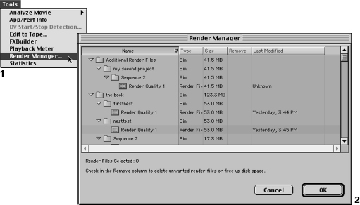
STEP 127
To illustrate this point, take the previously-rendered example using the two clips and the garbage matte on separate video layers. Render the clips so that your footage plays back correctly.
STEP 128
Using the Razorblade All tool from the Toolbar, make a cut in both clips on the same frame (Figure 6-105).
STEP 129
Use the Roll Edit tool to trim the newly created edit points in one direction or the other (Figure 6-106).
Now if you re-trim the edit points back to where they were, you will see that the red line has returned above the re-trimmed section of the clips, meaning that these sections must be re-rendered (Figure 6-107). The action of cutting and trimming the clips caused the render files linked to them to become unlinked.
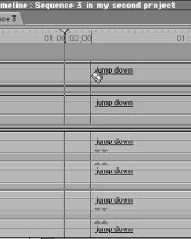
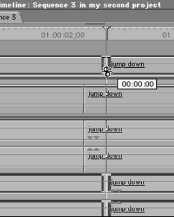
In theory, we haven’t altered the clips at all; we’ve merely cut on a frame, trimmed the clip, and then re-trimmed the clip back to its original length. Unfortunately, Final Cut Pro regards this as change enough and forces a re-render.
STEP 131
Return the two clips back to their normal rendered status (you can leave the razorblade-cut edit points, just Command-Z to undo the steps back to the point before you razorbladed).
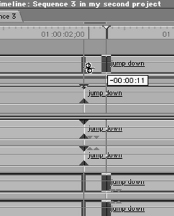
Select all the clips, go to the Sequence drop-down menu and choose Nest Item(s) (Figure 6-108).
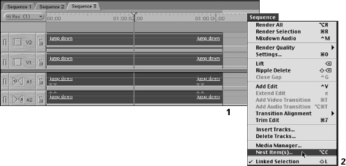
When you do so, you will be presented with a dialog box allowing you to name the new nested sequence. Do not leave the confusing default; name it something that makes sense to you (Figure 6-109).
You will be able to change the dimensions of the frame and the aspect ratio if you wish, but remember that you will have to render it if you do so, just as you would if you put the clips into a sequence that did not have the same frame size conventions of the original clips. This is essentially what you are doing, since the Nest Item(s) command creates a new nested sequence and includes the selected items in it.
Below this are options for retaining effects markers and audio levels with the nested items. This is important since Final Cut Pro will keep any adjustment you have made intact with the nested clips. The other checkbox included is the Mixdown Audio. This option may be useful in some cases. Remember that there is a limit to the number of audio tracks that Final Cut Pro can play back in real time. When you nest clips together, you also nest any linked clips together. Since two audio tracks are frequently linked to any video track you’ve captured, nesting repeatedly can lead to a situation where you have more than eight tracks playing back simultaneously, even though it appears that only two are.
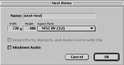

Mixdown Audio fixes this situation by quickly and discreetly rendering a Mixdown of the multiple audio tracks of the nested items. The sound will be the same, but you will remove the possibility of accidentally forcing Final Cut Pro to play back audio tracks beyond its capacity. You will still be able to go back into the nested sequence and change anything about the audio tracks if you wish after nesting.
STEP 133
Hit OK, and you will return to the sequence to find that the clips have disappeared and been replaced by what appears to be a single clip that bears the name of the nested sequence you just created (Figure 6-110). A glance over to the Browser will reveal that there is a new sequence icon in the project; it is the nested sequence you just created. Grab it and drag it over into the sequence and you will see that it is treated just as if it were a simple clip.
When you select Nest Item(s), all the selected items are bundled into one sequence that appears in your Project tab. All these items also seem to disappear in the sequence, but in fact they are just wrapped inside the nested sequence that appears on the sequence Timeline after the Nest Item(s) command.
STEP 134
Once again make a Razorblade cut, this time in the center of the nested sequence that contains the clips you just previously cut and re-rendered. Perform the same trim action on the nested sequence (Figure 6-111).
When you perform the same trim out and trim back in, you will find that the nest does not have to be re-rendered. This is because a sequence is being edited, not the nested clips inside the sequence. Since the sequence itself has no render files to become unlinked, no re-rendering needs to occur, even though the sequence’s contents have render files.
Do not become too confused by the concept of nesting items. It is a useful feature that becomes clear as you use it. Nesting can protect render files, as well as allow you to apply Effects Filters and Motion Effects to an entire sequence as a whole object, just as if it were an individual clip. If you understand these two functions, you can utilize the Nesting functions of Final Cut Pro in very productive ways.
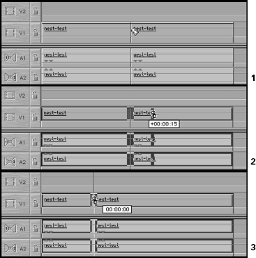
STEP 135
Double-click on the nested sequence in the sequence Timeline. Instead of opening up in the Viewer window as a clip would, the nested sequence opens up as yet another tab in the sequence Timeline window (Figure 6-112).
After all, a nest really is a sequence, not a clip, regardless of how it is being treated on the video tracks of the sequence. Double-clicking the nested sequence here, or in the Browser window will open the sequence up in the Timeline window as its own sequence tab. This allows you to go back into a nested sequence and make changes to the nested items if you must.
You can also load this, or any sequence, into the Viewer as if it were a clip in a couple of ways. You can grab the sequence and drag from either the Browser or parent (sequence the nested sequence sits in) into the Viewer window. You can also open the nest (or any sequence or clip) into a new Viewer, leaving the previous Viewer window open and loaded with its current clip.
To create a new Viewer window instead of replacing what is in the current Viewer window, hold down the Option key and double-click the sequence (or clip) icon in the Browser window’s project tab or bin. This will bring it up in its own new Viewer window. Incidentally, you can always create a new Viewer window for any individual clip in the Browser window by this same method. With individual clips, you also have the option of Control-clicking the clip in the Browser window and selecting Open In New Viewer (Figure 6-113). This option does not exist for sequences however, and you should rely on Option double-clicking for those. Clips in sequences on the timeline must be loaded into a Viewer window through the drag-and-drop method, or by selecting the clip and choosing Clip In New Window from the View drop down menu.
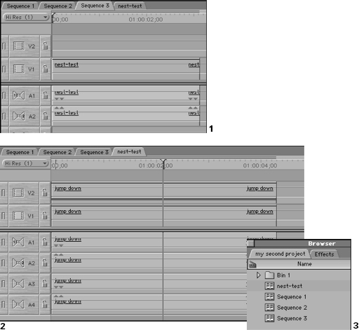
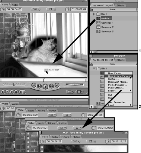
Once the sequence is loaded into the Viewer window, you will have access to the same tabs that you worked with on the individual clips. You may want to go through and perform the same exercise on the sequence that you did on the clips earlier so that you get the hang of using effects filters and Motion effects and experience the ease with which entire sequences can be processed as individual clips.