CHAPTER 2
Preparing AutoCAD Linework for 3ds Max
AT THE BEGINNING OF CHAPTER 1, I stated that the building block of any architectural scene is linework and that the vast majority of architectural visualization projects begin with AutoCAD drawings. Whether you model in 3ds Max or choose what I would call the more difficult approach of modeling in other programs such as AutoCAD, Revit, or Architectural Desktop, linework is where our work will always begin. Unlike users in other industries who can start with a simple primitive and use an endless number of tools to change the primitive into a highly complex character or some other free-formed model, those of us in the visualization industry cannot simply build architectural elements without the same drawings used to build the structures in real life.
This chapter demonstrates techniques that can be used to prepare this AutoCAD linework for importation into 3ds Max. If you choose to do the majority of your modeling in a program other than 3ds Max, then unfortunately, some of the techniques outlined in this chapter won’t apply. However, if you take my advice and conduct the majority (if not all) of your modeling in 3ds Max, then one of the most important phases of the 3D design process is the preparation of AutoCAD linework for 3ds Max. Simply put, knowing how to use the CAD linework found in a set of architectural drawings is a critical factor in fast, efficient work in 3ds Max. So in this chapter you will see how good preparation of linework in AutoCAD can allow the 3ds Max user to model many complex scene elements in just a few seconds. In reality, the techniques discussed in this chapter can be applied to any CAD program on the market. But because AutoCAD is by far the most widely used 2D CAD program in the world, this chapter is catered toward AutoCAD users.
The steps this chapter outlines to help you prepare AutoCAD linework for 3ds Max are as follows:
• AutoCAD setup
• Explore and examine AutoCAD drawings
• Consolidate drawings
• Clean linework
• Create new linework as necessary
After reading this chapter, you should have a thorough understanding of the process used to prepare AutoCAD linework for 3ds Max. Parts 2 and 3 of this book continue where this chapter leaves off by describing techniques for importing this newly prepared linework and using it to create various building and site elements.
AutoCAD Setup
After a few years of teaching 3ds Max, it occurred to me that an enormous number of intermediate level 3ds Max students have little or no working knowledge of AutoCAD. I imagine the biggest reason for this is that many 3ds Max users import linework in a different way than the way described in this chapter. Specifically, rather than spending time in AutoCAD cleaning the drawings and preparing the linework for a streamlined workflow, many users elect to import all of the linework from AutoCAD drawings and use this linework as a guide with which to create their models. For example, in Figure 2-1, you can see four elevations around the model of a house. Many users import drawings like this and model the various building elements with the appropriate elevation serving as a background and a guide. There is nothing wrong with this approach if it works for you, but I personally don’t believe it can compare to the speed and efficiency of the method outlined in this book, which uses the Loft command and/or Sweep modifier. However, before either of these features can be used efficiently, the AutoCAD linework must be properly prepared, and the best place to make these preparations is inside AutoCAD itself.
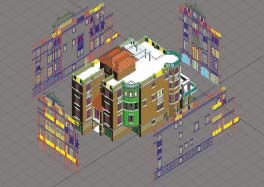
Figure 2-1. Imported AutoCAD elevations used as a guide for modeling in 3ds Max.
Since this discussion is based on the idea of maximizing speed and efficiency while preparing AutoCAD linework for 3ds Max, I thought it would be appropriate to first mention some fundamental concepts that deal with how the AutoCAD user interacts with the program. If you started using 2D or 3D software in the days of DOS based software, before icons and toolbars were available and when computer displays were much smaller, you probably have a much better appreciation for keyboard shortcuts and maximizing screen real estate. Whichever is the case, let’s take a few moments to look at a few things that might make working in AutoCAD much faster.
Customization
I don’t normally recommend customization to anyone who isn’t already very familiar with a program; however, since there are a few very simple customization changes you can make that can greatly improve your efficiency in AutoCAD, I feel that a short discussion about these changes is warranted here.
When you first install AutoCAD, you are presented with numerous toolbars and program settings that are not optimized for maximizing speed and efficiency, as shown in Figure 2-2. This image shows the default layout for AutoCAD version 2004, but the layout is very similar to even the latest release of the program. Incidentally, at 3DAS, we use 2004 because we don’t need any of the features in later releases, and Autodesk recently removed the 3DSOUT command. As you’ll see later, this command is critical to our workflow.
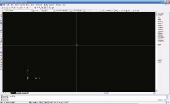
Figure 2-2. The default AutoCAD 2004 layout.
To maximize screen space you can simply right-click any toolbar and deselect those you don’t want to use, or click and drag them to the center of the screen and then close them one at a time. The only toolbars we keep on our screens at 3DAS are the Layers and Properties toolbars.
By typing Config, you can enter the Options dialog box, shown in Figure 2-3, and do a few more things that can speed up your work in AutoCAD. Within the Display tab, I recommend turning off the Screen Menu and scroll bars, both of which take up valuable screen real estate. The Screen Menu is the large menu interface directly to the right of your viewport. At the bottom of this tab is an option to increase your crosshair size and whether you use AutoCAD for 2D drafting or for importing into 3ds Max, this option should be set to 100% so the crosshairs stretch to the entire length of your screen window, thereby allowing you to use the crosshairs as a tool to check the alignment of lines on opposite ends of the screen.
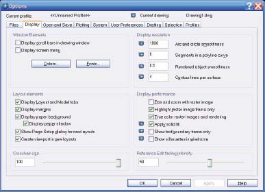
Figure 2-3. The AutoCAD Options dialog box.
If you make the changes described, your AutoCAD screen would look like the image in Figure 2-4, and you would have a substantial increase in viewport area.

Figure 2-4. AutoCAD with an increase in viewport area.
Inside the User Preferences tab of the Options dialog box is a button that allows you to customize the right-click button of your mouse. Whether you use keyboard shortcuts or icons to enter commands in AutoCAD, the Right-Click Customization button is an important feature to customize properly because doing so allows you to execute commands even quicker than using keyboard shortcuts with your free hand. In AutoCAD, there are three different modes you can be operating within, and how you customize this dialog box determines what happens when you press the right mouse button in each of these three different modes. I recommend setting up this dialog box as shown in Figure 2-5. In default mode, when no objects are selected, I recommend having a right-click mean Repeat Last Command. In Edit Mode, when one or more objects are selected, I recommend having a right-click mean Shortcut Menu. Finally, in Command Mode, when a command is in progress, I recommend having a right-click mean Enter. Configuring your right mouse button this way allows you to very quickly start the same command over again, open a shortcut menu and end a command in progress, which are perhaps the most commonly executed commands in AutoCAD, with the possible exception of the zoom and pan features, which should without a doubt be performed with the middle mouse button…once again a type of mouse configuration.

Figure 2-5. The AutoCAD Right-Click Customization dialog box.
Units
Another thing to keep in mind with every AutoCAD drawing you open is the drawing’s units. Unlike the previous configuration settings mentioned, units are stored with each drawing rather than the program itself. Before importing the linework from any drawing into 3ds Max, it would be wise to ensure that you know at what scale your drawing was created. Otherwise, you might find that your floor plans don’t fit properly into your project’s site drawing. In the U.S., architects create drawings so that 1 unit equals 1 inch. Civil engineers, on the other hand, create drawings so that 1 unit equals 1 foot, which means that before you import site drawing linework into 3ds Max, you determine whether you need to scale your drawings up twelve-fold to match the architectural drawings. As mentioned in Chapter 1, many architects create their own properly scaled version of the site drawing, using the civil engineer’s linework as a guide.
To change or inspect a drawing’s units, type units at the command prompt. Doing so opens the Drawing Units dialog box, shown in Figure 2-6. As an additional note, the precision specified in this dialog box has no effect on the accuracy of linework in AutoCAD or imported into 3ds Max.
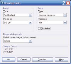
Figure 2-6. The AutoCAD Drawing Units dialog box.
Command Alias Editor
As mentioned constantly throughout this book, keyboard shortcuts provide a great way to increase speed and efficiency with 3ds Max. The same holds true with AutoCAD even if you use the program for nothing more than preparing linework for importation into 3ds Max. Keyboard shortcuts can drastically reduce the time it takes to interact with AutoCAD and considering that you might need to spend up to 25% or more of your total project time preparing linework in AutoCAD, the time savings can be enormous.
Keyboard shortcuts in AutoCAD are stored in a file labeled acad.pgp, and as of release 2004, this file is saved in the following location:
C:Documents and SettingsAdministratorApplication DataAutodeskAutoCAD 2004R16.0enuSupport
If you want to edit your shortcuts, you can do so by opening this file with a simple text editor such as Wordpad or Notepad. However, an easier way to do this would be through the Command Alias Editor dialog box found in the Express > Tools menu, and shown in Figure 2-7.
As an additional note, Figure 2-8 provides a list of important AutoCAD commands for anyone needing to prepare linework for 3ds Max. As with any 2D or 3D program, the most widely used commands in AutoCAD will undoubtedly be the pan and zoom commands, which are not shown in this list because they are best accessed with a middle wheel mouse button. If you have a solid understanding of just these 30 commands, there won’t be much you can’t do to efficiently prepare linework for importation.
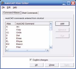
Figure 2-7. The AutoCAD Command Alias Editor dialog box.
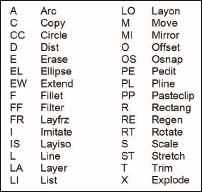
Figure 2-8. The top 30 AutoCAD commands suggested for learning with preparing linework.
Explore and examine AutoCAD drawings
One of the first questions a potential client will ask about 3D visualizations is how much does it cost. Pricing your work is arguably the most difficult and important part of your job if you are the owner or manager of a 3D visualization firm. As hard as it is, it would be far more difficult, and certainly more risky, to provide someone a quote on a project before ever looking at the project drawings. At 3DAS, we learned long ago, and sometimes the hard way, to never speak a word about prices before seeing a project’s drawings. There are numerous reasons for this, besides the obvious problem of quoting too low before realizing the true scope of work that lies ahead. One is that you don’t give yourself the opportunity to learn more about your client and the project he needs you to work on, both of which can influence the final price you set. Another is that without seeing the drawings, you should estimate high for a worst case scenario, and though you may tell the client you are in fact estimating high, he/she may be completely turned off by your over-inflated proposal. But the biggest reason you should thoroughly examine AutoCAD drawings before quoting a future project is that there are numerous ways drafters and architects can put a drawing together that will add an enormous amount of time to your work. We will look at most of these ways a little later, but suffice to say, you should avoid quoting a project before you are able to receive a complete, or nearly complete, set of architectural drawings.
The next part of this discussion deals with consolidating and cleaning your AutoCAD drawings, but before you can do either, you have to first examine all of the drawings your client provides so you have all of the linework needed to properly create all parts of the project. Our clients usually don’t know much about what we do or how we do it. Sometimes they just don’t care. Sometimes, the person we deal with is an architect, a real-estate agent, the owner of a construction company or some other person who is simply representing the owner who is actually paying the bill. Sometimes these contacts don’t even want or endorse the 3D visualizations we produce and only work with us on a project because they are forced to by the owner who insists on using 3D. Whatever the case may be, we sometimes have to beg, plead, and holler to get all the necessary drawings from our contacts, while other times our contacts simply throw us everything they have and tell us to find what we need.
Figure 2-9 shows an example of a list of AutoCAD drawings an architect provided us, perhaps not knowing or caring what we needed to do our work. As you can see, the list includes floor plans, site plans, elevations, and sections, the heart of what we need to do our work.
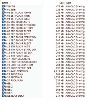
Figure 2-9. The AutoCAD drawings provided for a past visualization project.
As thorough as the list was, and as many unnecessary drawings as we were provided, there were numerous other drawings, which we didn’t rececive but needed to complete our work, to include landscaping, interior elevations, and furniture plans. All of these drawings were important to our project, and though we may provide a fairly accurate proposal without them, it’s an example of missing information that must be discovered early on so you can account for this lack of information in the proposal/contract to your client.
Equally important and often equally as difficult as calculating the pricing of a project is the calculation of a project’s schedule. In your proposal/contract, you should never specify a product delivery date if you don’t have 100% of the information you need to complete your project. Instead, you should provide your delivery date as a number of days from the time you receive all the necessary information. For example, Figure 2-10 shows a project schedule as specified in the PSA (Professional Services Agreement) for a particular project. Notice that it states that we have been provided with all architectural drawings, yet we still did not have other information we needed to complete our work. Because we had all of the architectural and site drawings, and because the information we lacked had only a minimal impact on the total amount of work to be performed, we were comfortable in providing a proposal. But we did not specify a product delivery date. Instead we stated that the product would be delivered in a certain number of days after all the information was provided.
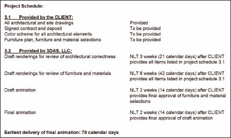
Figure 2-10. A suggested format for contractually displaying a project schedule.
As an additional note about the exploration and examination of AutoCAD drawings, after the next few sections of this chapter we will look at the basics of how to import AutoCAD linework. When we do, I will make a suggestion to import linework piecemeal, which simply means, import small parts of your linework, one at a time. There is a very good reason for doing this. Although you can certainly import an entire drawing into 3ds Max all at once, doing so will only convolute your screen, slow down your viewports and increase the time it takes to select and isolate certain objects. More importantly, however, if you import your linework piecemeal, it allows you to spend more time in AutoCAD figuring out what’s going on before you rush into the creation process in 3ds Max. When teachers administer a test in school, they often recommend to their students to answer the easiest questions first. This same philosophy works in the 3D world. By creating the easiest 3D elements first, you give yourself extra time to examine drawings and identify problems before spending valuable time creating something with incorrect linework.
Consolidate drawings
The next major step in preparing AutoCAD linework for 3ds Max is to consolidate all the pertinent drawings into one single drawing. This doesn’t mean that you have to or even should consolidate the drawings for numerous different buildings into one single drawing; but when you need to build a single major component of your project, like a single building, you should consolidate each of the pertinent drawings for that individual building into one single drawing file. There are 2 major reasons why this is a good practice to get into. First, it allows you to clean each of your drawings all at once, rather than repeating the same steps over and over for each drawing. Second, it allows you to find contradictory information and linework by having all of the drawings visible in one easy to see space and by allowing you to align different drawings together to see how each drawing compares to the next.
The process of consolidating drawings is simple. Open one of the drawings, copy all of the linework to the clipboard, paste that drawing’s linework from the clipboard into a new, blank master drawing, and repeat the process for each drawing that needs to be consolidated, which is usually the floor plans, elevations, and sections. Since many drawings use xrefs, you need to make sure that the drawing you open really contains the linework you need, rather than just an xref of the linework. In addition, always unhide and unfreeze all layers so you know that when you select and copy linework to the clipboard, you’ve actually copied all of the linework and not left any hidden or frozen linework behind. Figure 2-11 shows an example of linework from a three-story house consolidated from several different floor plans, elevations, and section drawings.
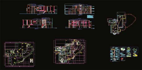
Figure 2-11. An example of a consolidated set of architectural drawings (elevations, floor plans, and sections).
Clean linework
Once linework is consolidated into one master drawing, the next major step is to clean all of the linework by the simple but often time-consuming process of isolating and deleting the linework on individual layers that contain unnecessary information. Sometimes you can select and isolate multiple layers at one time and delete all of the linework at once; however, you must be careful not to delete necessary linework that was placed on an inappropriate layer. It is not uncommon for drafters to place linework on the wrong layer, and while it may not negatively affect their ability to produce good construction documents, it certainly can be a problem for 3D users who expect to see a particular type of linework and all of that linework on a layer when that layer is isolated. For example, if you isolate the dimension layer of a drawing and don’t realize that the drafter carelessly placed critical wall lines on that layer, you might inadvertently delete those wall lines when you delete all of the dimensions. One way to avoid this problem in AutoCAD is to learn to use the Filter command so that instead of isolating layers, you can isolate (or filter) certain types of linework, such as dimensions. Refer to AutoCAD’s help files if you are not familiar with this command.
The previous image from the three-story house in Figure 2-11 showed an example of a ‘dirty’ drawing full of information we simply don’t need to do our work, such as dimensions, notes, electrical and plumbing fixtures, just to name a few. Figure 2-12 shows the cleaned version of the drawing. Notice that the section drawings in the upper-right corner of the image show notes of some sort; however, these sections are only for reference and never need to be imported into 3ds Max. They are just placed in the consolidated drawing so the 3D user can refer to them as needed.
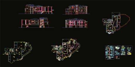
Figure 2-12. An example of a cleaned AutoCAD drawing.
I use the term ‘dirty’ to indicate drawings that contain not only information that’s useless for producing visualizations, as in Figure 2-11, but also to indicate drawings that contain linework that is not ideally suited for use in 3ds Max. What you don’t see in the ‘dirty’ image of Figure 2-12 is some of the many things that make the linework difficult to work with in 3ds Max. I use the term ‘clean line’ to indicate a line or spline that is free from any defects that would cause problems or errors in 3ds Max, and I use the term ‘dirty line’ to indicate a line or spline that is created or modified in some way that prevents its use ‘as is’ in the creation of 3D objects. There are several reasons why a line may be ‘dirty’, and hence, not usable when imported into 3ds Max. The following is not a complete list, but explains the majority of the reasons why linework is unusable when imported into 3ds Max.
Overlapping lines
This occurs when a line crosses over itself, as shown in the top-left image in Figure 2-13. When converted to 3D, this type of line often results in a solid that appears hollow or is missing a top and bottom.
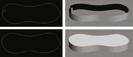
Figure 2-13. An example of overlapping lines producing improper results (top) and proper results (bottom).
Broken lines
This occurs when lines that should be continuous are broken into 2 or more individual segments, as in Figure 2-14. These segments may have endpoints close together, or they may be separated by a significant distance. If the end points are close enough together, they may be automatically welded when imported into 3ds Max; however, it is usually far more effective to identify these broken lines and weld them in AutoCAD. Waiting to fix this problem in 3ds Max will almost certainly take longer because of 3ds Max’s slower and less efficient line editing capabilities. Perhaps more importantly, if you leave the linework ‘dirty’ in AutoCAD, you may have to repeat the cleaning process in 3ds Max if you need to re-import for any reason.

Figure 2-14. An example of a broken line that would need to be repaired before use in 3ds Max.
Different layers
This occurs when lines that should be on the same layer are placed on separate layers, as shown in the multi-layered lines that represent the curbs in Figure 2-15. When isolating individual layers, this problem can lead to the user not realizing that he or she has just hidden information (on the wrong layer) and the result can be disastrous.
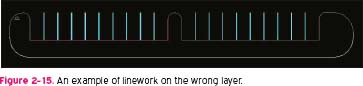
Figure 2-15. An example of linework on the wrong layer.
Varying elevations
One of the most frustrating things about working with drawings that somebody else creates is the eventual occurrence of line segments existing on varying elevations. From a top view, these lines may appear to be otherwise ‘clean’, but the truth soon comes out when you view your linework from a perspective view, as shown in the right image of Figure 2-16. In the left image, one cannot possibly know that the walls are actually created in 3D, which means that if you import this linework, you will actually be importing solids. Furthermore, if you decide to trace the existing linework (using snaps) rather than using the linework as is, you might find that the vertices of your newly created line exist at different elevations because one vertex may have snapped to the bottom of a wall and the very next vertex may have snapped to the top of the wall. You can fix this problem a few ways, such as with the Flatten command in AutoCAD, or within 3ds Max by aligning all the in vertices to the same elevation. Regardless, any method will take time and for large projects with numerous such occurrences, the total amount of time needed to clean the drawings properly could be enormous. This is yet another thing to keep in mind when inspecting drawings and providing a quote.
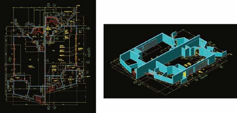
Figure 2-16. A 2D CAD drawing that is, unfortunately, not completely 2D.
The cleaning of these types of drawings may take several hours, and for very large projects, might take several days, but once cleaned, the linework can often be turned into complete 3D models in just minutes. This would not be possible, with any reasonable amount of accuracy, if the linework is not properly cleaned prior to import into 3ds Max. This process of cleaning linework will help you reduce unnecessary information on your screen and improve viewport navigation, and further provide you time to explore and examine your scene which can only help you identify problems early and reduce your chances of incorrect 3D models.
Orient linework
Once the master drawing has been cleaned, the next major step of the process is orienting the linework. The very first thing that should be done when beginning this step is to locate the origin. The linework you prepare, and therefore the model you construct in 3ds Max, should always be centered on the origin because 3ds Max is less accurate the farther away objects are from the origin. So start the orienting process by centering the site or the first floor plan of a building directly at the origin of a drawing.
If you are working on the construction of a site, then once you center the site, your work in the orientation of linework may very well be finished. You do need to ensure that your site plan is scaled properly, and knowing that most site plans originate from civil engineering drawings, I would always make sure to scale my site plan properly before importing the linework into 3ds Max. If you are constructing a building, however, then the process of orienting drawings is far more complicated and time-consuming. As with site drawings, you should always center all of your linework at the origin so that modeling in 3ds Max is done with the highest possible accuracy. The image in Figure 2-17 shows the same three-story house seen earlier in the chapter with all of the floor plans, elevations, and sections consolidated into one drawing and cleaned of all unneeded information. However, the drawings are not arranged in a manner suitable for importation into 3ds Max.
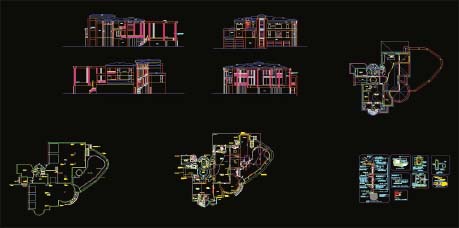
Figure 2-17. A cleaned AutoCAD drawing ready for proper orientation
The image in Figure 2-18 shows the same drawing with all the linework oriented in a way that makes working in future steps of this process (i.e., creating and importing linework) much easier. Notice that each elevation is oriented around each side of the first floor plan and rotated so that lines from the elevations can be projected against the floor plan to check for conflicts. All other floor plans are aligned in a row to the side for reference, as are sections and details.

Figure 2-18. An example of a properly oriented AutoCAD drawing.
So now that we’ve analyzed one project and how linework was prepared for 3ds Max, let’s take a quick peek at another project. Figure 2-19 shows a rendering of a building…
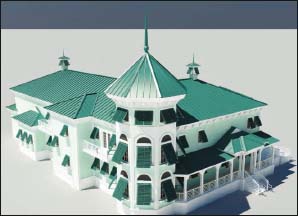
Figure 2-19. The rendering of the building shown in Figure 2-20.
…and Figure 2-20 shows the cleaned and oriented linework. As you can see, the elevations are again oriented around the first floor plan. One additional note about theses elevations – notice that there is an additional copy of each side elevation. These copies were created to prevent the need to turn one’s head 90 degrees to see the side elevations properly. Doing this makes working in this drawing a little easier.
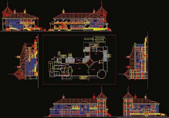
Figure 2-20. Another example of a cleaned and oriented drawing.
Create new linework as necessary
Once the linework is cleaned and oriented the next step is to either import the linework into 3ds Max as is, or create new linework to facilitate the construction process in 3ds Max. If you use the Edit Poly approach of building your models, also known as the box modeling method, then you may decide at this point to simply import the linework as a reference against which to build your models, as shown earlier in Figure 2-1. While this approach has its advantages, at 3DAS we greatly prefer to use the powerful and versatile loft and sweep features to create a large portion of the building and site elements of a project. In the next chapter, we’ll begin to import linework and look at techniques of using it to create various building and site elements.
At this point, we will look a little farther into this preparation process that uses the loft/sweep method by looking at how a drawing was arranged for another project. Figure 2-21 shows a rendering of the building we’ll be looking at.

Figure 2-21. A rendering of the 2D drawing shown in Figure 2-22.
And Figure 2-22 shows the linework as it appeared after it was consolidated and cleaned. However, the drawing still needed to be oriented, and since we always use the loft and sweep tools to create our buildings, additional linework needed to be created. Creating this new linework is the critical last step before the linework is imported into 3ds Max. Again, the process of importing linework and using it to create 3D objects will be discussed many times throughout the chapters that make up Parts 2 and 3 of this book.
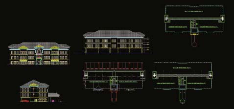
Figure 2-22. The cleaned and consolidated AutoCAD linework for the rendering in Figure 2-21.
Figure 2-23 shows the same drawing with the next two steps completed. Here you can see that the linework is oriented properly, but notice all of the other newly created linework. In the bottom-center of the image is a copy of each window and door. This linework is used to guide the creation of the 3D windows and doors within 3ds Max, and this process will be discussed in Chapter 4. Figure 2-23 also contains several horizontal lines running from the left elevation to the left side of the floor plan and several vertical lines running from the left half of the front elevation to the front of the floor plan. These lines were created to serve as a guide by which to place the windows and doors once created in 3ds Max. By importing these lines into 3ds Max and aligning a copy of the appropriate 3D window or door, you can precisely locate the position of each of these object types along the length of a wall.

Figure 2-23. The same drawing with oriented linework and newly created linework.
There are numerous other lines created besides those previously mentioned. In the bottom-middle of the drawing are lines that were used as profiles for the lofts created in 3ds Max. The lofts were used to create the walls of this building and the paths that these profiles were lofted around are co-located with the floor plan. In fact, the paths were created by tracing the existing linework, so the paths actually occupy the same space as the existing linework. By isolating the layers of just the newly created linework, you can see all of the linework that was created to build the walls for this project (Figure 2-24). Notice that each path is a different color. This helps distinguish one path from another once they are imported into 3ds Max.
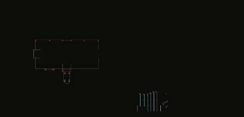
Figure 2-24. The newly created paths and profiles used to create the walls of this building.
Now let’s take a look at what this project looked like a little down the road. Figure 2-25 shows this building after lofts were created for the walls and after copies of the various windows and doors were placed in their proper location along the walls. Notice the lines that were used as a reference to place these copies. Once they were placed properly along the length of the walls using these lines, we needed to refer back to the AutoCAD drawings to determine the height of the windows and doors off the ground. Once they are in their final position, we can just explode all of these groups we copied and use the ProBoolean feature to subtract these objects that represent the volume of the windows and doors, from the lofts, thereby leaving behind a void in which those windows and doors are shown. This process is discussed at length in upcoming chapters.
Notice one other thing in this 3D scene. Only the left side of this building is being created. This is because the building is symmetrical and once the left side is created, a simple mirror routine will allow us to quickly duplicate the left half into the right half.
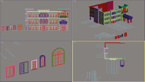
Figure 2-25. The same project with walls, windows, and doors in position.
Now this is just our preferred way of creating these fundamentally important objects - walls, windows, and doors. As mentioned, there are a few other methods some veteran modelers use to create these objects. Some use the box modeling method whereby the edit poly feature is used to carve out the windows and doors, sometimes using an XRef set of linework as a reference in a viewport. Some who use this method also incorporate lofts and sweeps to form their walls while others simply extrude the linework to do the same thing. While we feel strongly about our chosen method of creation, which method is best is a matter of opinion and based on the little nuances of how we all work. But what no veteran user will deny is that linework that’s not prepared properly in AutoCAD will lead to less efficient and less accurate modeling in 3ds Max. By taking the time to clean up drawings properly in AutoCAD, not only can you work faster and more accurately in 3ds Max, you have one other big advantage as well. The longer you spend in AutoCAD, the more time you have to examine the drawings and figure out how the project is being put together in real life. Not all drawings are easy to read, either because of the complication of the design or the lack of skill on the part of the drafter creating the drawings. But if you model your projects one component at a time (i.e., import the linework for the walls, build the walls, import the linework for the windows and doors, build these objects, etc.), you can identify and address drafting errors early on, rather than importing all the linework early on and realizing down the road that you have to recreate something because the linework was improperly created. And by importing clean linework piecemeal, you also don’t have to look through a mess of linework in 3ds Max to see the lines you actually need to work with.
Additional Notes
Up to this point, we’ve only looked at the preparation of linework for buildings, and while I would argue that the loft and sweep features are the best tools in 3ds Max to model a building, I know that other veteran users would want to make the case for their own methods. This is especially true when you consider that many users prefer to model using B.I.M (Building Information Modeling) capable programs such as Revit. But when it comes to creating sites, I would argue that the way we have figured out to create sites is truly the fastest possible. That’s a pretty bold statement, but after trying every conceivable way of creating site elements, we’ve found that nothing else even comes close.
So let’s just look at how some site linework was prepared for some past projects and see how that linework can be used in 3ds Max to quickly create the various site objects. Figure 2-26 shows an example of a very dirty drawing. This is a site drawing that was created by a civil engineering firm and as is typical with civil drawings, there is an enormous amount of information unnecessary to visualization work. Cleaning a drawing this large with this amount of unnecessary linework could take half a day, but the time spent preparing the linework properly here in AutoCAD is well worth it because once this linework is prepared properly, you can easily model the entire site in less than 30 minutes.
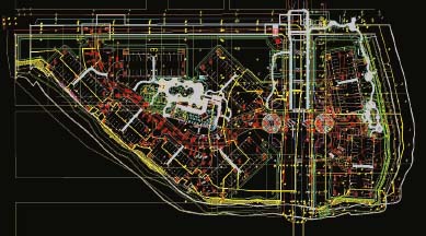
Figure 2-26. A very ‘dirty’ site drawing.
Figure 2-27 shows what the drawing looks like once the linework is cleaned and prepared for import.

Figure 2-27. The ‘clean’ version of the site drawing.
Notice that if I select and isolate the linework representing the roads, as shown in Figure 2-28, it is in fact just one continuous closed polyline. If I import this polyline in 3ds Max, I could simply add the Edit Mesh or Edit Poly modifiers and right away the roads would be completely modeled. The same line could also be used as the path for a loft or a sweep, and thus used to create the curbs along the side of the roads. If I were to isolate the lines that represent the mulch beds, retention ponds, sidewalks, pavers, or any number of site elements, you would see the same kind of good, clean, closed polylines that are shown in Figure 2-28. Each of these could be turned into renderable mesh or poly objects or used to cut out these various site elements from other site elements. Each of these different site elements can usually be created in less than a minute once the linework is properly prepared.

Figure 2-28. Isolating the roads of the site reveals one continuous spline.
As one final example of the speed of creating 3D objects with clean linework, notice the clean site drawing in Figure 2-29. This image shows the linework representing a shopping center. In the parking area around all of the buildings you can see hundreds of parking lines and road lines. When you receive a site drawing with these lines, they are shown as just that – lines. However, if you turn these objects into polylines with a width of 6 inches, the typical real world width of parking lines, you can quickly turn these polylines into a renderable object in 3ds Max.
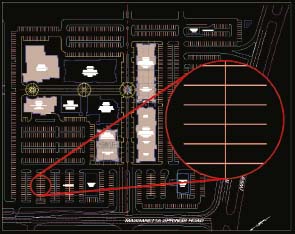
Figure 2-29. A ‘clean’ site drawing with hundreds of parking lines that can be modeled in seconds.
If the road lines are continuous lines in AutoCAD, as opposed to the dashed lines you see on many roads in the real world, then you can simply import a drawing file of those lines and turn them into a renderable object. However, if you do have dashed lines anywhere in your drawing, such as in the lines shown in Figure 2-30, you can use a unique characteristic of the 3ds file type to have those areas with dashed lines also imported.

Figure 2-30. Dashed road lines that can be exported as a 3ds file and quickly modeled in 3ds Max.
This is a really great thing because if you couldn’t have these dashed lines accounted for automatically, it would be very time consuming to manually build these breaks into the linework, especially if they occurred in the bend of a road. Each of the dashed segments is not an individual line but rather one line with a dashed linetype style. If I isolate these lines and export them as a 3ds file, when I import them into 3ds Max, the dashed linetype style will automatically generate an editable spline with these dashed segments built-in. By adding the Edit Mesh or Edit Poly modifiers, I could turn these splines into a renderable object. Remember, if I just imported this dwg file, I would lose these spaces that give these lines their dashed appearance.
As an additional note about this technique, there is a command in AutoCAD called LTSCALE, which stands for linetype scale. If you use this command, you can increase or decrease the segment lengths of these dashed lines as well as the spacing in between them. The LTSCALE value you set will ultimately determine what the imported spline will look like.
And there’s one final point that should be mentioned here about the workflow described in this chapter. If you’re wondering why we don’t recommend linking linework as opposed to using the techniques outlined in this chapter, it’s because file linking uses the AutoCAD DWG file type rather than the Legacy file type. Because of this, you experience the same problems as you would if you import with the AutoCAD DWG file type. Specifically, vertices are often converted unintentionally from Bezier to Bezier Corner vertices.
Summary
This chapter provided a general overview of how to prepare AutoCAD linework for 3ds Max but it really only scratched the surface of the entire process. With each year seeing improvements in CAD software, we are getting closer to a perfect software package that allows the user to build great projects in 3D, while concurrently using the same software to produce construction documents, which is a process coined by the term BIM (Building Information Modeling). However, no matter how great the software is, I think that we will never see the day when these programs can out-do the speed, efficiency, and accuracy of these fundamental modeling techniques outlined in this chapter. Certainly you can create a building in literally seconds with these software packages today; however, you can’t do the same with buildings of any real complexity. Even if you could, you’d have to spend a great deal of time creating all of the unique wall, window, door, and roof styles before you can even start creating your models. The ability to create precise site plans in 3D is really not even possible using the same BIM method that some people use to quickly generate buildings. The bottom line is, preparing AutoCAD linework properly can be time-consuming, but it’s an important process that when done effectively can save a tremendous amount of time and grief in the long run.