
Chapter seven
Specification of materials—soil, sand and gravel
7.1
Methods of specifying particle-size composition
7.1.1
The need for precision
Choosing the best materials from those on offer locally can make all the difference to the efficiency of construction. Cost and availability can be misleading as the market tends to be geared more to the needs of the civil engineer and the builder than to those concerned with sports turf. The increasing density that comes with the progressive interpacking of smaller and smaller particles within the pore space formed by larger particles is a virtue for making concrete. It is not a virtue when seeking maximum pore volume for water movement and easy root penetration.
The commonly available 10 mm (3/8 in) gravels (SN7 in Table 7.1) and the 5 mm (1/14 in) concreting sands (SN10 in Table 7.1) are often loosely defined only by the upper limit of the particle sizes present, but for sport turf we need to be more precise. At the very least we need to know both the upper and lower limits of the particle-size range and may even require a full particle-size grading so that other properties, such as hydraulic conductivity, can be estimated with sufficient precision for design purposes.
7.1.2
Particle-size grades
For the classification of particle-size grades used in this publication see Tables 1.3 and 7.1. Tabulated information of this type can be used for identification and to assist in specification. However, the evidence revealed by graphical representation can often be more useful as it makes comparisons easier. Two such methods of display are described: a triangular graph explained in section 7.1.3, and a summation graph explained in section 7.1.5.
A triangular graph (the Triangle of Texture) is used to indicate general differences based on percentage composition expressed as sand, silt or clay. It is of particular value for comparing soils likely to reflect properties associated with these three very broad particle-size categories. For comparisons within a narrow range of particle-size grades, e.g. the categories spanning the sand and gravel grades at the coarse end of the particle-size spectrum, a summation graph is often more appropriate.
7.1.3
Triangle of Texture
For the mineral skeleton of a soil, texture classes have been traditionally defined by reference to a Triangle of Texture such as that currently used by soil surveyors (Figure 7.1(a)).
TABLE 7.1 Drainage and soil materials for sports turf
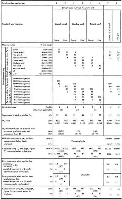
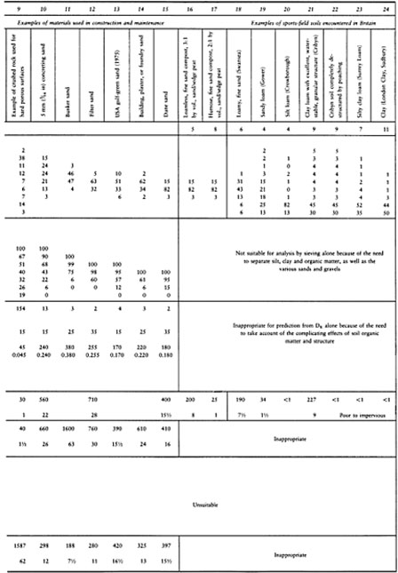
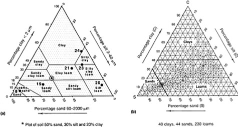
FIGURE 7.1 Determining soil texture class, (a) Soils SN18–24 from Figure 7.3 and Table 7.1 plotted on a Triangle of Texture, (b) Plots representative of the texture of English and Welsh soils, based on a systematic sampling of information in soil survey records, Nos 1–56, and the soil memoirs for Leeds, Cardiganshire, Aylesbury and Hemel Hempstead.
This is merely a triangular graph with values for percentage sand (nominally 2.0–0.060 mm in diameter), silt (0.060–0.002 mm) and clay (less than 0.002 mm), read off on each axis. A line for each value is then projected into the triangular diagram, parallel to the side directly opposite the 100% value for the category concerned. As an example, the plot for a soil, 50% sand, 30% silt and 20% clay is shown on Figure 7.1(a) as an asterisk. The other plots are for the soils numbered SN18–24 in Table 7.1.
The areas delineated within the main triangle are the different texture classes. These are subjective in origin, reflecting handling properties of value for identification in the field, and behaviour characteristics of significance for agricultural management.
The second Triangle of Texture, Figure 7.1(b), shows the distribution of plots derived from a systematic sampling of data available for the soils of England and Wales in 1979 (Stewart et al, 1980). This is included to indicate the relative proportion of soils within the broad texture classes—sands, loams or clays—and the extent to which the soils in series SN18–24 (Table 7.1) are typical.
7.1.4
Specifications based on sieve size gradings
Because of the inefficiency of sieving as a procedure for fine particle fractionation at the level of silt and clay, this approach is used only for the characterization of materials, predominantly sand, gravel or stone. Normally the results are tabulated, or plotted on summation graphs.
The least precise method of defining particle size by sieving is to use only the smallest sieve size through which all the material has passed, e.g. 10 mm (3/8 in) gravel. Such a material could
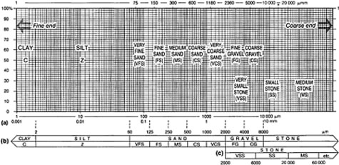
FIGURE 7.2 Summation graph. (a) Engineers' values expressed as the percentage passing sieves of progressively smaller mesh size; therefore, plot downwards from coarse to fine. *=14 000 µm sieve also used. (b) Soil scientists' categories separated by sieving or sedimentation, each expressed as a percentage of the whole range of particle-size categories to be included in the total. Enter the progressively accumulated values, starting from the fine end of the particle-size spectrum. (c) Alternative categories for the coarser particles outwith the fine earth range (Appendix A, Table A.3).
consist of particles ranging widely in size or, for example, particles ranging only between 10 and 5 mm. The true nature of the material will depend very much on the nature of the deposit being worked and the extent to which it has been cleaned of fine particles by washing.
7.1.5
Summation graphs
Materials are sorted by sieving into their particle-size composition and then the various categories plotted cumulatively as percentages. A zone, as defined on a summation graph, delimits the range of tolerance allowed for particular materials.
The summation graph used for this purpose indicates the particle sizes on a logarithmic scale (Figure 7.2). This allows fine particles, such as clay and silt, to be included in a graph that also allows for special attention to be given to details of grading within the much larger but less widely spaced categories of sand and gravel. The vertical axis is a straightforward linear scale from 0 to 100 representing the sum of the percentages for the individual particle-size fractions. The plot representing the composition of any particular material can be built up by plotting individual particle-size percentages cumulatively, starting at the fine end. Alternatively, data in the form normally supplied by the sand and gravel industry, i.e. percentages passing each sieve in a bank of progressively smaller sieve sizes, can be used by starting to plot at the coarse end. The steeper the line on the graph the narrower the range of particle sizes present.
Figure 7.3 shows:
- the plots of individual materials listed in Table 7.1 for comparison with Stewart zones (see also section 7.1.6);
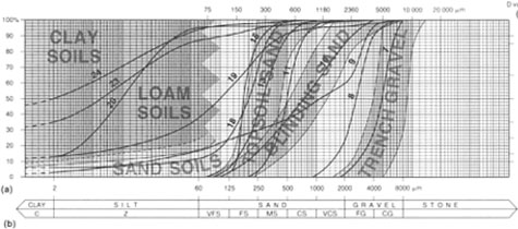
FIGURE 7.3 Summation graph of selected materials from Table 7.1. (a) Sieve-size categories used by engineers, (b) Particle-size categories used by soil scientists, (c) D values, i.e. summation totals used to indicate particle diameters of special interest. See also general key, Figure 7.6.
- the region within which the fine end of the loams and clays plot out. These are the soils which have to depend on cracks, old root runs, worm channels and particle aggregation for drainage. They are the prime candidates for supplementary, artificial drainage when subject to intensive use (section 2.2);
- the region between the topsoil sands and the loams and clays where the sand and loamy sand soils plot out. This region, like that of the loams and clays, can only be precisely defined at the fine end of the texture spectrum. Though not pure sands these soils are likely to continue to drain freely so long as the small amount of silt and clay present remains heterogeneously distributed or trapped within water-stable granules.
7.1.6
Grading zones
British Standards Specifications for aggregates and sands
The system used by suppliers of aggregates to the building industry is based on British Standards Specification BS 882 1201: Part 2, 1973 and the later amended version, BS 882:1983 (see particle-size zones plotted on summation graphs, Figures 7.4 and 7.5). These define fine aggregate material from natural sources as used for making concrete, but lacking anything better, these standards have also been used in specifications relating to the construction and maintenance of soil-based facilities used for sport. Unfortunately, the objectives of those using fine aggregate to make concrete are not the same as those aiming to assist soil drainage and promote the growth of grass (section 7.1.1). Though the BS categories do include materials suitable for sports-field use the boundaries are not sufficiently well drawn to serve without need for additional, qualifying statements (compare Figures 7.4 and 7.5 with 7.6).
Stewart zones
To facilitate greater precision in the specification of materials required for sports-turf construction and maintenance it has been necessary to define new particle-size zones. This has involved research based not only on technical
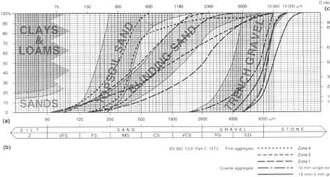
FIGURE 7.4 Summation graph illustrating BS (1973) zones for fine and coarse aggregate materials, (a) Sieve-size categories used by engineers, (b) Particle-size categories used by soil scientists, (c) D values, i.e. summation totals used to indicate particle diameters of special interest. See also general key, Figure 7.6.
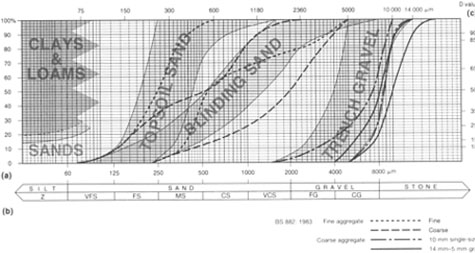
FIGURE 7.5 Summation graph illustrating BS (1983) zones for fine and coarse aggregate materials, (a) Sieve-size categories used by engineers, (b) Particle-size categories used by soil scientists, (c) D values, i.e. summation totals used to indicate particle diameters of special interest. See also general key, Figure 7.6.
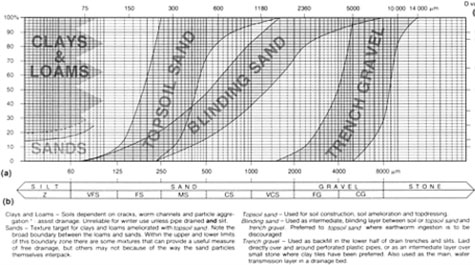
FIGURE 7.6 Summation graph defining Stewart zone materials for sports-turf constructions, drainage and maintenance, (a) Sieve-size categories used by engineers, (b) Particle-size categories used by soil scientists, (c) D values, i.e. summation totals used to indicate particle diameters of special interest.
requirements but also on availability. The result is the summation graph zones in Figure 7.6 and the particle-size categories defined in Tables 7.1 and 1.4. To avoid confusion with the previously used British Standards, developed primarily for the making of concrete, these new zones are identified in this book as Stewart zones and the materials they characterize designated topsoil sands, blinding sands and trench gravels. If these become generally accepted they will encourage the standardization of efficient designs and assist in precise specification.
Topsoil sands are suitable for top-dressing and topsoil construction. Blinding sands are for bringing permeable backfill through to the surface over gravel or for use as an intermediate layer between a fine-textured topsoil and an underlying gravel bed, preventing the soil from infiltrating the gravel. Trench gravels are suitable: for the gravel element in a two-part sand/ gravel slit; as permeable fill in a trench over a perforated plastic pipe; for use as the gravel bed in a rafted construction.
The advantages of these categories are listed below.
1.They are safe because any material falling within them will not infilter the material of the zone immediately adjacent. For example, a Stewart zone topsoil sand-will not infilter a compact Stewart zone blinding sand, nor will a Stewart zone blinding sand infilter a compact Stewart zone trench gravel.
2. A compact Stewart zone topsoil sand will blind out most soils and a Stewart zone blinding sand will be too coarse for earthworms to eat their way through.
3. A Stewart zone trench gravel will not pass through the perforations of a plastic pipe and yet, when compact, will be small enough to avoid being infiltrated by a Stewart zone blinding sand placed above it. Hence, only two of these materials are required to form a stable, permeable link between a perforated plastic pipe and the soil surface.
4. The Stewart zone trench gravels, though small, have a sufficient hydraulic conductivity for every centimetre used in the bottom layer of a two-part slit to add a safe minimum of 1 m to the interval between the intercepting pipe system. This assumes that the overall design rate does not exceed 50 mm (2 in) per day and slit spacing does not exceed 20 times slit width. The standard schemes described in this book all comply with these requirements.
In fact, these incremental allowances may be applied to any trench system filled with a Stewart zone trench gravel running flat to the next relieving tier of underdrainge: for example, gravel channels 150 mm (6 in) wide, spaced in parallel succession at 3 m (10 ft) intervals. Here a 30 cm (12 in) depth of a Stewart zone trench gravel would allow for the relieving pipe system to be spaced at a safe minimum of 30 m (33 yards). This could be increased to 45 m for a trench gravel plotting wholly within the coarser half of the trench gravel zone, but for trench gravels whose particle size distribution spans most of the trench gravel zone, or in case of doubt, use the safest and simplest, 1 cm: 1 m relationship (Table 7.1).
5. The zone limits are not based only on theoretical considerations but reflect, both in their form and in their range, materials that are currently widely available.
7.1.7
D values and gradation indices
To make full use of a summation graph, a form of shorthand is used to indicate the particle diameter D reached at any specified cumulative total: for example, a topsoil sand with D 85-D 15 consists of particles within the range 600–140 µm in diameter. These values can be read off a summation graph where D 85 represents the particle diameter D at 85% of the cumulative total, and D 15 is the same at 15% of the cumulative total. This would allow for a maximum of 15% of particles larger than 600 microns and a further 15% smaller than 140 microns. Of the actual materials listed in Table 7.1 only SNS 12–15 would comply with this requirement.
This approach can also be used to define a ‘gradation index’, i.e. a number indicating a degree to which any normal, fairly symmetrically graded material peaks around the average particle size. For this purpose we generally ignore the small percentage of particles at the largest and smallest extremes and concentrate on the ratio of the upper and lower limits of the particle-size range spanned by the bulk of the material. Thus we can describe the dune sand, SN15 in Figure 7.3, as having a D 90/D 10 gradation index of 270/140=1.9. The 270 represents the particle size in µm at the 90% cumulative total and the 140, the particle size in µm at the 10% cumulative total. By contrast, the concreting sand, SN10 in Figure 7.3, has a D 90/D 10 gradation index of 2500/190= 13.2, this relatively large value reflecting the much wider range of particle sizes present. SN7, the 10-mm 3/8 in gravel in Figure 7.3, has a D 90/D 10 gradation index of 6600/2750=2.4. This again is a small value, typical of a single-sized aggregate.
In fact the gradation index (often quoted as G.I. for short) reflects the slope of the middle portion of the summation curve. A small value (less than 3) corresponds to a steep slope between the particle-size limits chosen and, as the value increases from 6 to 20 or more, so the slope represented is more obliquely inclined.
For typical, quartz-dominated sands and gravels we can assume that a material with a D 90/D 10 gradation index of the order of 2 will have a bulk density of the order of 1.5- 1.6 g/cm3 and a pore volume approaching the theoretical maximum, for an unstructured material, of 40%. As D 90/D 10 gradation indices increase beyond 6 and up to 20, so bulk densities are liable to increase towards a maximum of around 1.75–1.80 g/cm3 with pore volumes decreasing to 33%. However, it should be noted that shelly or very angular materials, or materials with very high G.I. values (e.g. SN9 in Figure 7.3, a crushed rock material used for hard porous surfaces) do not conform very well in the field with these predictions as they tend not to pack homogeneously. With soils there are additional complications introduced by organic matter and structure so that, outside the normal run of sands and gravels, the gradation index approach loses much of its significance and tends not to be used.
7.1.8
Using D K to predict hydraulic conductivity, critical tension and pore-size compatibility
When selecting the best sand and gravel from locally available materials, or when using drainage schemes that do not conform in their dimensions to those assumed in the Stewart zone approach (page 117), it may be necessary to get some idea of the hydraulic conductivity or critical tension of the materials on offer. The practical procedures for doing this precisely are probably best left to the specialist, but experience suggests that a reasonable estimate can be made, within a 20% margin of error, by reference to the particle-size composition.
Predicting hydraulic conductivity
This prediction can be achieved in two steps.
1.Determine D K, the particle diameter that effectively represents the dominant influence on the hydraulic behaviour of the material under consideration. The K in this context refers to the symbol K used to signify hydraulic conductivity, but hydraulic conductivity is only one of the values which the D K particle size can now be used to predict.
Thus, it might have been more usefully designated the D E value, the effective particle diameter, for it can also be used to predict critical tension, capillary rise and pore-size compatability with other materials. It remains as D K however, reflecting its original use. To determine D K, one of the following procedures will be appropriate.
(a)For materials with four or more particle-size categories (as defined in Table 7.1) greater than 5%, or a D 90/ D 10 G.I. over 4, use D 15 as the D 10 value. For example, this would apply to SN10 in Table 7.1, indicating from its summation curve (Figure 7.3) a D Kvalue of 240 µm.
(b)For materials with three or less particle-size categories of 1%+, or a D 90/D 10 G.I. less than 3, use D 35as the D K value. For example, this would apply to SN15 in Table 7.1, indicating from its summation curve (Figure 7.3) a D K value of 180 µm.
(c)For all other materials use D 25 as the D K value. For example, this would apply to SN8 in Table 7.1, indicating from its summation curve, a D K value of 2020 µm.
(d)Check with the general formula suggested by Thornton (1978, p. 503):
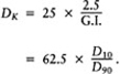
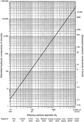
2.Use the data in Table 7.2 or the graph, Figure 7.7, both of which relate D Kto an estimated value for the saturated hydraulic conductivity K.
Thus, for the examples cited in (a), (b) and (c) above, we can arrive at the estimated
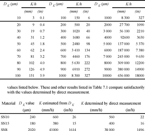
Predicted, approximate values for hydraulic conductivity are probably all that is required for normal design purposes, but it must be appreciated that supplies from quarries will vary to some degree from the sub-samples analysed, and that the procedure for the direct measurement of hydraulic conductivity is itself subject to error. A major problem with direct measurement is that the laboratory conditions under which K is measured— homogeneity of packing and degree of saturation—are very unlikely to be exactly replicated in the field. It would help greatly, therefore, if all sand and gravel suppliers provided data on particle-size composition when offering materials for sale so that K can then be estimated by the procedure given above.
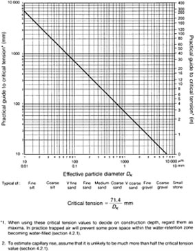
Predicting critical tension
For critical tension it is necessary to start by following through the procedure described above for determining D K from particle-size composition. An approximate value for critical tension can then be estimated by substituting D K for particle diameter in the equation developed for this purpose in section 4.2.2:
Thus, for a typical dune sand (SN15 in Table 7.1),
Alternatively, read value directly off graph, Figure 7.8.
Predicting pore-size compatibility
D K may be said to define the particle diameter most likely to dominate the pore system of a mixed particle-size sand or gravel. As such it provides a useful basis upon which to decide if two otherwise unlike materials, laid one above the other, will blend hydraulically or behave as separate layers, tending to create a perched watertable above the junction.
1.When a relatively coarse sand is introduced between a topsoil dominated by fine sand and a gravel drainage bed, the primary objective may be to keep the three layers separate, but will the pore system controlling water movement between the two sand layers effectively merge, or will the two layers remain hydrologically separate?
If the D K values of the two sands are very similar then it can be assumed that they will merge hydrologically. Therefore, when designing with critical tension in mind, the depth of the blinding-sand layer should be included with the depth of the fine sand topsoil to define the total height of the construction above the gravel drainage bed.
2. Except when trying to germinate seed we normally want water to work itself well down into the soil in the hope that the roots will follow. What will be the effect of changing from a coarse to a fine sand topdressing? Will the change encourage undue water retention at the surface, adversely affecting aeration?
Only if the D Kvalues of the two materials in a layered sequence are very similar, or the D Kof the lower material is smaller, will the two materials combine to keep water moving freely across the junction. However, if the D K value of the next layer below is significantly larger than the layer above then the downward migration of water will be held up at the interface until the top layer is saturated. Therefore, avoid unnecessary layering of hydrologically incompatible materials unless, as with a very coarse sand, blinding layer, or a gravel drainage bed, this is what is intended to help retain some water within reach of the surface.
Do not gratuitously introduce complications by unnecessarily varying your topdressing materials or you may introduce unwanted layering effects.
7.2
Choosing the correct materials according to function
7.2.1
Introduction
Though several methods developed for the precise specification of soil-forming materials make use of data on particle-size composition, experience suggests that the easiest to implement is likely to be one based on zones defined on a particle-size, summation graph or in a table of sieve-grading limits. The following review of features likely to influence choice of material according to function will therefore be based mainly on materials defined in Figure 7.6, or Tables A1.3 and A1.4 in Appendix A.
7.2.2
Choosing the correct soil
In situ or imported topsoil should be free of glass and other potentially dangerous material as well as being in a structurally water-stable state, i.e. in ‘good heart’ (section A.7). As such it will probably have a pH in the region 5.5–7.5 and an organic matter content between 4 and 10%. Thereafter, the performance of the soil will depend very much on its particle-size composition. It is impossible to predict from a knowledge of particle-size composition alone whether any particular soil will drain badly. However, if the soil when compact has the potential to drain badly because of its content of fine particles, it should be considered a likely candidate for intensive, supplementary drainage.
Sand, silt and clay content of the ‘fine earth’
Soils with less than 75% of the fine earth (particles less than 2 mm in diameter) consisting of sand, or more than 25% silt+clay are the loams and the clays (e.g. Table 7.1, SNs 19–24). They are soils dependent on worm channels and particle aggregation to maintain a structure favourable to the rapid infiltration of surface water. They are unreliable for winter use unless pipe-drained and slit.
By contrast, soils classified as loamy sands or sands (e.g. Table 7.1, SN18) have so little silt and clay that only when this fine material is concentrated into a layer will there be a risk of developing a problem of drainage impedance. Loamy sands or sands are soils with less than 25% silt plus clay and, as such, are good prospects for sports turf, generally requiring under-drainage only. (See note on Sands, Figure 7.6.)
If a sand soil is to be ameliorated by addition of a strongly granulated loam, no effort should be made to break down the granulation and homogenize the two materials or the drainage efficiency of the sand will immediately be compromised. The aim should be to achieve a ‘spotted dog’ effect, i.e. granules of soil set in a matrix of sand. This is best done by careful mixing when dry.
Soils dominated by very fine sand and silt (e.g. Table 7.1, SN20) are particularly difficult to deal with because they are water-holding, structurally very unstable and liable to wind-blow when left bare during construction. They may well benefit from steep grading (e.g. 2.5% or 1 in 40) to ensure that excess water will be shed off the surface.
Topsoil quality
Soil from a stockpile may well be structurally unstable in water, readily capping when rained upon. This would be typical of subsoil but could also be topsoil that has deteriorated during storage. No matter how good the original quality of a topsoil, it will rapidly deteriorate in storage during the course of a single growing season, especially if soil temperature, soil aeration and soil moisture are adequate for biological activity to continue.
Storage under dry, cold, well-aerated conditions, or grassed over in a heap no more than 60 mm (2 ft) high, would be much less harmful. In the normal large stockpile, biological activity goes on but, because aeration below the surface is restricted, the supply of oxygen is greatly reduced and the nature of the microbial activity changes. This results in the dissipation of organic matter and production of noxious end-products. The structure deterioration that follows may require many years of special management to rectify.
Soil degradation is a problem far more widespread than is generally recognized. It probably stems from the skills of our engineers in earth moving having gone beyond their knowledge of soil as a dynamic, biological system. Before the advent of modern heavy equipment, earth-moving projects were achieved by manpower and a system of skips and rails; a procedure which probably limited the extent of such operations and the degree of compaction caused.
By careful selection of site we should aim at minimum disturbance and only very minor grading within the topsoil, preserving soil structure and the organisms responsible for it. Time should be allowed for re-consolidation and root-binding after the loosening consequent upon the disturbance involved in grading. It is important to realize that unless the topsoil is fresh and not structurally degraded by stock-piling, it may prove quite unsuitable for the satisfactory establishment of a sports-turf sward. Note the adverse effect of structural collapse on hydraulic conductivity in the clay loam soil, SN22, Table 7.1.
In summary, if non-sandy soils are to have a satisfactory air/water balance for root development, they must be selected for their desirable structural state and then handled so as to preserve it. When using such soils the aims should be as follows.
- Avoid disturbance if at all possible so that full benefit can be derived from existing worm channels and well-established, subsoil cracking systems.
- If the soil has to be disturbed, work it only when it is dry enough to be brittle. Take every precaution to avoid either dusting or panning by injudicious and over-zealous use of machinery.
- Avoid storage; if at all possible, arrange for direct transfer. If storage is necessary, then recognize that rapid structural deterioration will take place in a time span to be measured in months rather than years.
Stones and boulders
Stones and boulders should not be so large or so numerous as to interfere with the smooth progress of a slit trencher machine. This means that stones larger than 75 mm (3 in) in any dimension are liable to be unwelcome in the top 300–450 mm (12–18 in) of soil.
Total stone content should not exceed 15% by weight, 8% by volume, as even at this moderate level of stoniness all the soil agitation inherent in harrowing, raking and frosl action will tend to leave them concentrated on the surface where they are least acceptable. To merely roll them back in is like forcing marbles into porridge with predictable, adverse effect on surface infiltration.
In time, surface casting by earthworms will bury stones, but a made-up or severely disturbed soil is not likely to be well endowed with earthworms initially, and the rate of reburial by this means is, in any case, bound to take years. In practice, therefore, any adverse concentration of stones at the surface should be dealt with by some process of mechanical removal before grassing up; particularly so if the stones are sharply angular fragments that could cause injury. Far better to avoid these problems by careful soil selection in the first place.
Peat
To be described as ‘peaty’ a soil needs to contain more than 25% dry weight of organic matter, about two-thirds organic matter by volume. A true peat is made up of more than 35% dry weight of organic matter, more than three-quarters organic matter by volume (Figure A 1.3, Appendix A).
Deep peat, once adequately drained, can provide a satisfactory grass surface for sport, especially for controlled use by juveniles, but there are special problems, unique to peat, that have to be taken into account.
1.Peats vary, most typically, according to their origin. Deep, fen-type peat is formed in the hollow of a natural catchment and, because of the stable nature of the ground water-table and the natural sequence of vegetation through which it has been built up, it may have a fibrous, reed-residue layer at the base. This can be utilized for the efficient, lateral discharge of drainage water once a satisfactory outfall has been established. Bog peats accumulate as a blanket in very high rainfall areas but are liable to dry out seasonally. This means they may be quite well humified and compact throughout, requiring a system of underdrains to assist with lateral discharge.
2.If the watertable is lowered, particularly in a fen-type peat, there will be considerable subsidence. Initially this will be as a result of the de-watering process but will then continue, albeit at a slower pace, because the peat itself will decompose in response to the improved aeration. These two processes can lead to falls equivalent to one third of the fall in the watertable height.
Though initially a saturated, fibrous peat may have a hydraulic conductivity comparable with that of fine sand, the combined effect of shrinkage and decomposition can reduce this to a value more comparable with silt. This may not yet make it unduly limiting for vertical infiltration down to the watertable but it would be very slow for clearance laterally.
It is important, therefore, that we should recognize not only the initial differences that may occur between peats but also the changes in performance that are likely to occur with time, especially if the site is completely de-watered. For example, there may be no benefit to be gained from attempting to de-water a basal layer of fibrous peat. This could be left waterlogged so that it could maintain, by efficient lateral flow, the water level in a peripheral ditch forming part of a pump drainage scheme, or a height-controlled outfall.
3.Improved aeration on sites showing the visual warning signs of ‘oily’ sheens on the surface of ditch water, or of red ochre staining around springs and drain outfalls, can lead to major problems caused by a build up of iron ochre deposition (section 2.1.3). If iron ochre deposition does occur it will be particularly devastating in the aerated channel system of slits and pipe under-drains.
4.There may be some difficulty over organizing a satisfactory outfall to allow the water-table to be lowered and maintained at an appropriate level. This may entail clearing a passage through a natural drainage barrier or turning instead to some form of pump assistance. In either event this problem should be thoroughly explored with professional help from the local drainage authority.
5.Because of the low density of drained, moist peat (about a quarter of the drained, moist density of a loam or a sand) and the risk of shallow rooting, any grass sward established may not be sufficiently anchored to resist the tear-wearing stress of studded footwear. As already pointed out in section 1.10.6, this would be much more of a problem with adults than juveniles.
6.The virtual necessity of an open ditch approach to ground-water control requires serious thought being given to the frequency with which balls will require to be recovered from this location. Though recovery poles may be made available for this purpose the menace of vandalism may result in their not being available to casual users. In these circumstances the task of ball recovery from open, slippery-sided, water-filled ditches will at best be a nuisance and, at worst, may constitute a serious child hazard.
With the above problems in mind, a peat project is best tackled in stages, first concentrating on lowering the ground watertable to no more than 1 m (1 yard) below the playing surface. This is probably best done initially by a well-maintained system of ditches around individual pitches, linked up to an effective, controlled outfall.
Once de-watering has stabilized the surface enough to take the necessary light weight, load-spreading machinery, progress can be made with weed killing, removal of trash and regrading by minimal re-distribution of peat. Then the surface can be fertilized and firmed up by pushing out a carpet of topsoil sand, 50 mm (2 in)—100 mm (4 in) thick, according to resources. Finally the surface can be grassed and maintained as advocated in Section 6.1. Only if, after 2–3 years of use this fails to satisfy should any consideration be given to the possible benefits of pipe and/or slit drain supplementation.
Tip sites
It may be found that the existing surface on a tip site is seriously contaminated with dubious or potentially harmful materials such as glass and noxious chemicals, or half-buried obstacles such as large stones and boulders, concrete, metal, refuse, etc. It is normally unwise to attempt to clear such objects by trawling
through the soil with a subsoiling device; farbetter to aim at safe burial.
After clearance of all loose debris and obstacles standing proud of the surface, burial may involve importation of 450 mm (18 in) of good soil, sufficient to avoid any adverse effect of frost heave, and to allow adequate clearance for soil cultivation and drain trenching. Since this should be regarded as a minimum safe depth, an additional allowance of one-sixth of the final desired depth should be made to take account of long-term settlement.
If noxious chemicals are suspected, and these cannot be entirely removed by excavation, the surface to be buried should first be chemically screened by a 50–75 mm (2–3 in) layer of at least 25 mm (1 in) of lime, and then 25 mm (1 in) of peat. The lime will tend to inactivate by precipitation, and the peat will tend to trap by chelation. These layers should be firmed into place by rolling and thereafter should not be disturbed.
Should there be any doubt over the stability of the tip surface or the height to which the new surface can be raised, then the tip surface should be trued off with a freely permeable, blinding layer of coarse sand, fine gravel or grit (unless already screened with peat and lime) and covered by an appropriate, synthetic filter membrane prior to topsoiling. Where the drainage scheme to be adopted requires pipes to be installed under the filter membrane these will have to be linked by permeable fill through the filter membrane. If the imported topsoil is a free-draining sand, or loamy sand, this may suffice, but if the imported soil will require slit drainage, provision may have to be made to continue the permeable fill in the pipe trenches well above the filter membrane. This can be done by piling the required trench gravel in ridges on the membrane surface, along the line of the pipe trenches. Alternatively, by marking the line of each pipe run with duct tracer tape (or equivalent), connection can be made later by trenching the link down from the new surface.
Obviously it would be advantageous to start with a stable tip, suitably trued off and blinded, and then to take time to find an adequate amount of good topsoil to build up to the desired 450 mm (18 in). However, if only a shallow depth of topsoil is to be used over a synthetic filter membrane, a great effort should be made to secure a sufficiently sandy soil so as to obviate any need for further amendment by slitting. In either case, the details of the design need to be carefully worked out as any later upgrading that requires trenching into the buried pit material could be very disruptive.
7.2.3
Choosing the correct sand and gravel
Because of the great importance of choosing the correct materials this subject has already been considered in Chapter 1 and the concept of the topsoil sands, blinding sands and trench gravels introduced on page 114 to simplify precise specification.
Sands for topdressing, soil amelioration and whole soil construction
These are typically the Stewart zone topsoil sands: the dune, filter, plaster and foundry sands listed as SN12, 14 and 15 in Table 7.1 and Figure 7.3. They have D 50values between 0.18 and 0.40 mm and D 90/D 10 typically between 2 and 3.
When choosing a sand to ameliorate a soil, or for topdressing, the particle-size grading should be matched to the dominant, medium-to-fine particle-size category in the topsoil already in place. This will discourage any tendency to develop the sort of layering and interpacking that inhibits the free movement of water in a vertical direction. Additionally, for golf and bowling greens, where the topsoil has already become biologically stabilized under acid conditions, the sand should be lime-free. To verify, check for the absence of vigorous fizzing when the sand is treated with a 10% solution of hydrochloric acid. However, where the in-situ topsoil has become biologically stable at an alkaline pH then top-dressing with a sand that is slightly calcareous will not harm. It will not upset the established biological equilibrium and, therefore, will not allow ephemeral disease organisms the opportunity to invade. Sand for use as the primary ingredient in a specially constructed, sports-field topsoil should be in the finer half of the topsoil sands, with D 50 in the region of 0.18–0.22 mm, like SN15 in Figure 7.3. This will help to develop the tractive efficiency required for vigorous games. On bowling greens, where drainage can be given priority over traction, a medium particle-size sand with D 50 more in the region of 0.27–0.31 mm (SN12–14 in Table 7.1) would be preferable if locally available at an acceptable price.
Sands for use in layered constructions, and in slit and pipe trenches
These are typically the Stewart zone blinding sands found amongst the concreting sands (SN10 in Table 7.1, Figure 7.3) with D 50 between 0.5 and 1.3 mm and D 90/D 10 between 8 and 23.
Blinding layer sands have to be looked at from several points of view.
1.Because they are relatively wide-ranging in their particle-size composition they will tend to interpack and form a relatively stable surface to work over.
2.For most blinding sands the D 15 particle-size grade will tend to determine the effective pore size and, if this matches the D Kparticle-size grade in any sand layer immediately above, the effective pore size will tend to be continuous through the two layers. This will then allow the two layers to function more or less as one with regard to the vertical infiltration of water, e.g. SN14 in Table 7.1 laid over SN10.
3.As blinding layers are frequently the layer sandwiched between fine sand above and gravel or small stone below, their particle-size grading should be specified so as to ensure that they will hold out the fine material above and not themselves infilter the gravel or stones beneath. To maintain a stable, layered system, and erring on the side of caution, the D 15 of the blinding layer should generally not exceed four times the D 85of the fine material above. That is, the main range of larger-sized particles in the fine material above should be large enough not to filter through the necks of the pores formed by the main range of smaller-sized particles in the blinding layer below. Similarly, the D 15of the underlying gravel or stone must not exceed four times the D 85 of the blinding layer.
Generally, for symmetrically graded sands and gravels made up of sub-angular and rounded particles, the procedure for determining the effective upper and lower particle-sizes can take into account the narrowness of the particle-size grading. Thus, D 15and D 85would be appropriate parameters for a wide particle-size grading, D 35 and D 65 for a narrow particle-size grading, and D 25and D 7 5 for something intermediate between these two extremes. An important feature of the Stewart zone materials is that any Stewart zone topsoil sand will remain stable over any Stewart zone blinding sand, and this in turn will remain stable over any Stewart zone trench gravel (Figure 7.3 shows plots of typical materials with their D 15, D 25, D 35, D 65, D 75 and D 85 values indicated)
4.Where appropriate, because of the local supply situation, advantage can be taken of the reliably small perforations in plastic drainage pipes to allow the use of a suitable, washed grit, or washed concreting sand, immediately over the pipe. For this the appropriate D 85, D 75 orD 65 of the backfill material should exceed 4 mm (1/10in), i.e. twice the maximum width of the pipe perforations. However, because of the tendency for the particles in loose grits and concreting sands to segregate during handling, a good deal of the fine material may weep through into the pipe before a stable, coarse-particle envelope is established around the pipe. In practice, therefore, it is usually more expedient to search widely for a Stewart zone trench gravel for this purpose, especially as this type of material is also likely to be required on site for any associated system of sand/gravel slits.
5.For clay tiles the problem is the possibility of pipe misalignment, and for this reason only, the normal practice of using 20–32 mm (3/4-11/4 in) stone can be justified, but an additional blinding layer of trench gravel will then be required to allow a blinding sana to continue the permeable link through to the topsoil.
6.Where sand is intended to form a permeable link through the topsoil, the sustained permeability of this link may be threatened by the activity of earthworms consuming the sand and mixing it with the adjacent soil. In this position, however, we should also avoid too open a material, such as a 10–15 mm (3/8–5/8 in) gravel which earthworms can squeeze through, plugging the pores with fine soil as they go. In this situation a blinding sand has the advantage of being dominated by pores too small for earthworms to squeeze through yet it is mainly made up of particles larger than 0.5–0.7 mm which are too large for most earthworms to consume.
Gravels for use as permeable fill in slit and pipe trenches and drainage beds
These are typically the Stewart zone trench gravels, single sized 10-mm (3/8-in) aggregate with D 50between 4 and 9 mm and D 90/D 10less than 6 (e.g. SN16 in Table 7.1 and Figure 7.3). In sports-turf drainage there is seldom a need to contemplate the use of anything larger. To do
so is to invite problems of infiltration by soiland the need for extra blinding layers.
Such gravels are used under sports turf for several purposes:
- as a drainage bed beneath a specially constructed topsoil;
- as backfill immediately over perforated plastic drainage pipes;
- as the gravel fill in pipeless drainage channels;
- as the gravel layer in two-part sand/gravel slits.
A useful feature of the Stewart zone trench gravels already pointed out (page 117) is that every centimetre depth of gravel used at the bottom of a normal two-part slit allows for an additional one metre run between interception pipe laterals.
Soil, bound by grass roots, seems generally to remain stable except where there is active redistribution by earthworms. However, where soil is liable to lie wet, as beneath a gravel bed, some regard should be paid to the extent to which the D 85 of the soil is less than a quarter of the D 15 of the adjacent gravel. If this indicates the likelihood of soil infiltration it may be necessary to blind the soil with an appropriate blinding sand, or a synthetic filter fabric which has similar blinding properties. Only where there is a real risk of ground water surging up from below, as on a flood plain or a lowland coastal site, is it sometimes necessary to contemplate extending the use of synthetic filter fabrics to lining the walls of drainage trenches.
Soils will increase in stability according to clay content and degree of water-stable granulation. However, where silt (SN20 in Table 7.1) or fine sand forms the bulk of the soil, a check should be made on the nature of the backfill over the pipe and in the other drainage trenches to ensure that the soil will not infilter laterally. For this, check that the D 15 of the adjacent backfill is not more than four times the D 85of the soil.