
Chapter four
Design criteria-theory and practice
4.1
Transmission of water
Calculations are described in Chapters 4, 5, 7 and 13 that should be part of the stock-in-trade of any professional designer, but not everyone involved in sports-turf provision will feel that their concern obliges them to immediately get so deeply involved. Others, though wishing to make the effort, may initially experience difficulty because the practical objectives are not yet sufficiently clear in their minds. Anyone thus deterred might do well to move on first to page 62 of this chapter,chapter 7, pages 114–117 and then to Part 2, returning to the more detailed calculations when the need seems more clearly to justify the effort. Those with special skills in mathematics are referred to Appendix 5 where the subject is considered at the fundamental level necessary to generate the equations used for design purposes in the main text of the book.
4.1.1
Theoretical considerations affecting design calculations
Darcy's Law
Darcy's law is the fundamental law which describes the flow of water through porous media. It is very similar to other fundamental laws of physics that describe the flow of electricity and the flow of heat. These state that, in the first instance, the flow is a characteristic of the medium, some media being inherently better conductors than others. Thereafter, for water, the flow is directly proportional to the hydraulic head providing the push and inversely proportional to the resistance as determined by the nature of the pore system and the path length through it. Thus Darcy's law may be written
where Q is the quantity of water flowing per unit time, K is the hydraulic conductivity of the medium, A is the cross-sectional area through which water flow is limited, H/L is the hydraulic gradient, H being the hydraulic head, i.e. the height of the continuous water column of free standing water within the medium and above it, and L the length of the path through the medium controlling flow.
Hooghoudt's drain-spacing equation
Dr Hooghoudt (1940) of the Netherlands published an equation which, on a level site, describes the interrelationships of all the factors controlling the lateral discharge of drainage water through soil to drainage trenches when input is balanced by output. The conditions envisaged are illustrated in Figure 4.1 (a). At equilibrium the watertable is held at a fixed height H above the level of the water in the drainage ditches. In these circumstances Hooghoudt's equation states
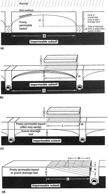
Hooghoudt's drain-spacing equation has been used. Construction typical of general amenity grass areas where pipe placed within trench, cut into impermeable subsoil and linked through to surface by permeable fill. (c) Construction for intensifying used sports turf where a gravel drainage bed underlies a sand-dominated topsoil, or where surface water is channelled through the topsoil into a sand/gravel slit system, linked across pipe, drain trenches. (d) Model used for the heuristic purpose of illustrating how the simplified version of Hooghoudt's equation may be conceived as quantitatively describing the discharge of water through a saturated soil to a drainage trench.(pages 59–62)
where S is the drain spacing, K is the hydraulic conductivity of the free-draining soil, H is the maximum height of the watertable over the level of the water in the drainage ditches, V is the rainfall in equilibrium with drain discharge, d is the depth of free-draining soil from the surface of the water in the ditches to the surface of the next layer below which can be considered to be impermeable.
This equation is in fact a special case dealing with horizontal discharge, in two directions, across a level site, with unimpeded discharge through the entire exposed face of each of the outfall ditches. This follows upon the more general, fundamental work of the Russian Kamenskii (1938). For consideration of the case where there is some impedence to discharge in the ditch walls, pages 61–62; for consideration of the effect of slope and for discharge in four directions page 66.
Hooghoudt's equation applied to sports-field drainage
Theory
I.G.Daniells, who was researching on sports-field drainage in Aberystwyth during the period 1972–75, pointed out that in most sports-field situations where intensive drainage is required the pipe, with permeable fill above it, is placed in a trench cut into relatively impermeable subsoil (refer to Thornton, 1978, pp. 36–40). Drainage water is then directed to the drain trenches in one of the following ways:
- through a special layer of very free-draining soil on top of the impermeable subsoil, as in Figure 4.1(b);
- down through a very free-draining topsoil and then laterally though a specially constructed gravel bed to the drain trenches, as in Figure 4.1(c);
- through special channels cut into the existing relatively impermeable topsoil and made permanent by filling with sand overlying gravel; very similar to Figure 4.1(c) so far as the slits are concerned.
In all these circumstances the variable d in Hooghoudt's equation has no value so long as the pipe can clear all water reaching it without excess accumulating in the trench. This then allows the further simplification to
When comparing Figure 4.1(a) with Figures 4.1 (b) and 4.1(c) it is important to note that in (b) and (c) the water cleared sideways falls into the drain trench from above. The pipe is installed at a depth that keeps it well clear of damage from construction work carried out over it, and the drainage link with the surface is maintained by permeable fill. Water tumbling discontinuously down through the gravel in the pipe trench will contribute no extra pull and should not feature, therefore, in any assessment of hydraulic head. H should only take account of the height of the watertable perched above the surface of the impermeable subsoil and should not include any additional allowance for the depth of the pipe.
When choosing an overall design rate for drainage the aim should be to avoid surface ponding caused by the watertable breaking through the surface. Any water infiltered should be cleared without this happening. Surface ponding resulting from soil conditions impeding infiltration should be treated separately. In the circumstances depicted in Figure 4.1(b) it might sometimes be more reasonable to design for the maximum height of the watertable H to be held just below the surface at peak capacity, for example 75 mm (3 in) down.
When utilizing a gravel bed (Figure 4.1(c)), as for golf and bowling greens, it can be assumed that lateral flow will take place through the gravel bed as if it existed in isolation from the overlying topsoil, its full depth being considered the maximum height available for any watertable perched within it. This leaves the sand soil above to be designed solely with regard to efficient infiltration, vertical drainage, plant growth and playing character. In the similar circumstances of sand/ gravel slits, lateral discharge is also best considered to be determined only by conditions within the gravel layer. The sand above is, to the gravel layer, merely the conduit through which the water to be cleared arrives.
To pursue the subject of water movement through soil, quantitatively, requires advanced mathematics. This is the purpose of Appendix 5. However, for those who are not mathematicians a heuristic approach based on the model illustrated in Figure 4.1(d) will serve as an adequate starting point from which to proceed to the intelligent use of Hooghoudt's equation and its extensions.
In Figure 4.1(d) flow is conceived as taking place across the drainage layer in a tightly packed arrangement of small, square tubes, all sloping down diagonally from the surface towards the nearest outlet end of the free-draining layer. The total amount of water moving laterally increases progressively as further increments enter from above and, in the model, probably unlike reality, the soil beneath the main diagonal is virtually redundant.
When in equilibrium at peak capacity the rainfall which the model is designed to accept just matches the water discharged through the pipe-trench face. For this shunting through of water to be simultaneous it must take place when the tubes are full, i.e. the soil is saturated.
Consider the situation in just one of the tubes, starting at distance M from the drain trench and discharging at the trench face, a distance N from the surface. The flow through this one tube can be quantitatively described by Darcy's Law
where q is the infiltration required at the inlet end of the tube, K is the hydraulic conductivity of the medium in the tube, a is the cross-sectional area of the tube, N/M is a reasonable approximation to the hydraulic gradient, M being very close to the path length through the tube when N (normally 100–200 mm) is very small compared with M (normally 100000–200000 mm).
Or, as all the tubes are conceived as grading uniformly, and N and M are proportional in length to H and L,
and the total flow through all the imagined tubes, to all intents and purposes, aggregates to
where, referring also to Figures 4.1(b) and (c), Q is the total amount of rain, represented by the volume VL W, which must be cleared through the topsoil to achieve the desired design rate, and A is the approximate cross-sectional area of all the tubes discharging drainage water through the trench face with area HW. Substituting VL W for Q and HW for A,
which can be simplified and re-arranged to
Since L=S/2, i.e. L is half the drain spacing, we have
which re-arranges to
All these are forms of the simplified Hooghoudt drain-spacing equation and may be used as they best fit the type of calculator available. The dimensions must all be expressed in the same units, e.g. S and H millimetres (inches), K and V in millimetres (inches) per hour.
In reality, flow is not constrained within tubes and does not traverse the drainage layer in straight lines, but the result from the heuristic model, where approximations of this kind have been used to simplify the mathematics, appears to be identical to that reached by Hooghoudt's more rigorous approach. The fact is that the relationship summarized in Hooghoudt's standard equation holds only over the normal range of conditions encountered in constructions for sport. However, as shown in Appendix 5, Hooghoudt's drain-spacing equation tends to slightly exaggerate performance. The error increases in significance as S becomes progressively smaller compared with H but, even at spacings only of the order of 1 m and H values of the order of 300 mm, the error is unlikely to exceed 1%.
Practical considerations affecting design for drain interception of slits
If the area through which water is free to discharge through the trench face is restricted, e.g. where the intersection between the gravel layer in a sand/gravel slit incompletely intersects the gravel fill in a pipe trench or gravel channel, the heuristic model suggests this may reduce the rate of discharge significantly. The effect will be seen in the adjustment required in the H2 factor of the standard Hooghoudt drainspacing equation. One of the two Hs involved should be reduced to represent the actual height of the window through which the drainage water can discharge at the trench face, i.e. the intersection link. The other H, representing the maximum height of the watertable over the level of the water in the drainage ditches, is unaffected. The message here is that, for maximum efficiency in a linked, tier system of drainage channels, the main discharge routes—normally the gravel layers—should intersect to the full depth of the gravel layer in the discharging tier.
In Figure 4.1(c), however, which is probably closer to reality, it is assumed that water accumulation in the freely permeable layer will reach a peak midway between the pipe trench outfalls, while clearance needs only take place through the base of the vertical, discharge face.
When it comes to effecting links of this nature in the field, e.g. between sand/gravel slits and pipe underdrains, these conflicting assumptions lead to two different conclusions on the most effective way to organize the junctions. Theoretically, Figure 4.1 suggests that in Figure 11.1, the layout for a standard slit system, the gravel layer in the slit trenches needs only a minimal depth of intersection with the top of the gravel layer in each of the pipe trenches. What is illustrated is intersection to the full depth of the gravel layer in the slit trenches: hence the range of alternative depths indicated for the soil and gravel layers in the pipe trenches.
However, since it would be possible for the watertable at the mid-point between the drain outfalls to rise further, into the layer of blinding sand above, and even on to the surface temporarily, there needs for this reason alone to be some generosity in the design of the outlet from the slit into the pipe trench, as the heuristic model allows. At the same time, the gravel drainage layers must be protected as much as possible from soil invasion by placing them as deep as possible, away from the topsoil where most of the lateral tunnelling of earthworms takes place. Thus the option to avoid any unnecessarily deep intersection between the slits and the pipe trenches should not be at the expense of overall slit depth. Figure 4.1(c) suggests that it would be theoretically acceptable to reduce the gravel layer in the pipe trenches to the absolute minimum required for a clean, horizontal link between the gravel at the base of the slits and the surface of the gravel in the pipe trenches. This would work, however, only if the flow through the horizontal interface was adequate, because there would be no option for any substantial additional discharge sideways, along the pipe trench.
In the field we must expect to encounter practical difficulties over ensuring so critical a link without allowing a large margin for error. Should the normal differential settlement between the trenches and the soil lead to a drop in the relative height of the gravel at the top of the drain trenches and the gravel at the bottom of the slits, or should additional drains be required after slitting, there will then be a risk, with a tight design, that the vertical, outfall face of the slits themselves will be unduly restricted to allow for peak flow. Thus, for practical reasons, the design of the vital link between the slits and the pipe trenches should err on generosity in a new construction. But there is some margin for adjustment when the specification has to be tight, or when installing slits to upgrade the drainage provided by an existing pipe system, if soil conditions do not favour deep trenching.
Preliminary note on the Stewart zone approach to design
When designing a drainage system involving superimposed sandy topsoils, or artificial, vertical drainage, bypassing the soil en route to the pipe system, the aim should be first to evaluate the flow required through each separate part of the integrated system then, secondly, to select materials that will meet these requirements, avoiding bottlenecks, and getting maximum benefit for minimum cost.
In Chapter 7, pages 114–117, the Stewart zone system is described. This develops the idea of working with a limited range of the most commonly available materials, chosen to make efficient design and specification much easier by eliminating the need for elaborate calculations. This approach will be demonstrated throughout the remainder of this chapter, after examples have been worked through by the more rigorous procedure of precise calculation. first example, page 71.
Fitting values to factors K and V in the simplified Hooghoudt equation
Hydraulic conductivity K available for lateral discharge through materials considered uniform
Whatever the drainage medium through which water must pass to reach the pipe drains, whether it be soil, sand, gravel, or some special mixture, it is necessary to know the rate of flow through the material in question. This will be at a peak when saturated. It is this value, the saturated hydraulic conductivity, that we determine in the laboratory and use to determine from theory the nature of the backfill and the width, depth and spacing of the drainage channels required to achieve any target design rate.
As indicated in Table 4.1 a granular loam may have something like the hydraulic conductivity of dune sand, 200–400 mm/h (8–16 in/h), when in ‘good heart’, i.e. when the granulation is water stable. The same soil, destructured and compact, as it may well be on the abused surface of a soccer pitch, can drop down in hydraulic conductivity to 0.05 mm/h (1/500 in/ h), a value more typical of subsoil. Casagrande and Fadum (1940) give values of 360 mm/h (14 in/h) for well-structured topsoil (a value equivalent to that for dune sand), 3.6 mm/h (1/7 in/h) for the beginning of poor drainage, and 0.003 mm/h (1/7000 in/h) for a soil that is practically impervious (compare SN21 and SN22 in Table 7.1)
For many British soils the change from ploughed topsoil to unploughed subsoil indicates a hundred or thousand-fold drop in hydraulic conductivity. This means that, in effect, the lateral discharge of excess surface water to pipe systems is mainly confined to flow over the surface or through the topsoil.
TABLE 4.1 Permeability and drainage characteristics of soils (adapted from Casagrande and Fadum, 1940)
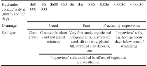
In most calculations concerned with rapid drainage, any slow discharge through the subsoil can be considered no more than a gratuitous bonus.
It is this dominating influence of the topsoil in lateral flow that must be taken into account when deciding to what height the permeable fill over pipes should be brought. If the surface becomes structurally degraded and infiltration so slow that the surface is frequently ponded, this can only be relieved by arranging for effective surface interception into purposemade vertical channels, bypassing the soil and linking directly through to pipe underdrainage. Similarly, if the space available for water storage below ground has been filled it is hydraulic conductivity in the horizontal direction that is crucial for the discharge of any further excess. In worm-worked soil, for example, vertical infiltration of water down earthworm burrows may be very rapid, but the eventual benefit to drainage will depend on the general rate of dispersion through the surrounding soil and the frequency with which the temporary storage capacity of the burrow system is exceeded.
Values for the hydraulic conductivity of isolated, disturbed samples of soil in the laboratory are unlikely to relate very well to performance in the field. For uniform materials, such as the sands and gravels installed as horizontal layers in special constructions, or in the vertical channels of a drainage scheme, packing is uniform and water movement is potentially the same in all directions. Therefore, in these circumstances hydraulic conductivity determined in the laboratory can be assumed to relate closely to that which can be expected to assist drainage in the field. However, the hydraulic conductivity of a material determined under ideal conditions of saturation in the laboratory is likely to be an exaggerated version of that which occurs in situ. In the field the pore space is liable to become partially blocked by trapped air, especially when water filters down from above. Compensatory effects working in the opposite direction are: (a) the care taken to achieve maximum packing density when loose materials are tested in the laboratory, whereas less perfect packing is likely to prevail in the field; (b) channels, assumed in a calculation to be of the precise width shown on the plans, frequently are to some degree wider; (c) the soil, usually assumed to contribute nothing to rapid drainage, may in fact make some contribution. Theory and practice will therefore diverge but still much can be done by calculation to locate possible bottle-necks so that materials or dimensions that could not possibly achieve the target design rate can be eliminated.
Because the hydraulic conductivity K of the medium is the factor in the simplified Hooghoudt equation for which a reliable value is normally least readily available, actual values for typical materials are given in Table 7.1. In Part 2, where specific constructions are described, the outline specifications for typical schemes utilize only Stewart zone materials. Any modification involving the use of materials that fall outwith the prescribed Stewart zones will require the whole scheme to be reviewed and appropriate adjustments made by calculation.
Averaging hydraulic conductivities available for lateral discharge through layered systems
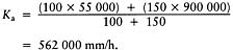
Where two freely permeable materials are to be laid in layers, one above the other, e.g. in a two-part, sand/gravel slit, it may be appropriate to assess their combined effect K a for the lateral discharge of drainage water. This can be done by using the following formula to determine an average value, weighted to take account of the hydraulic conductivity and depth of each of the layers concerned. The average
However, the contribution of the sand layer in such a system is primarily to allow excess water down to the gravel layer below and it is in the gravel layer tliat lateral discharge predominantly takes place. This is why no allowance is made for the contribution to lateral discharge made by the sand layer in the simple. Stewart zone approach (Chapter 7, page 117).
Design rate V
The design rate is the rainfall in millimetres (inches) which it is desired to clear through the system in a given time. It is the factor V in Figure 4.1.
As explained in Chapter 1 (pages 13–14), a design rate for sport and recreation in Britain might vary anywhere between the two extremes of 12 mm (1/2 in) of rainfall a day and 12 mm (1/2 in) of rainfall an hour, depending on climate, the demands of the game and standard of play.
When specifying design rates it should be appreciated that 2 mm (1/10 in) per hour is about the minimum rate for hard porous surfaces (Chapter 13) and anything much in excess of this for turf is going to require vertical clearance of rainfall through a sand, or loamy sand topsoil to a gravel bed. Where lateral discharge has to take place through the topsoil itself—either the whole topsoil or sand slits—maximum design rates are unlikely to exceed 2 mm/ h (2 in/day). A minimum rate normally considered to be reasonable for a sports ground in Britain is between 1 and 2 mm/h (1 and 2 in/ day), according as rainfall ranges between 500 and 1250 mm (20 and 50 in) a year.
Where, for reasons of economy, the under-drainage is inadequate to cope with the consequences of short periods of intense rainfall, provision should be made to grade the surface to a fall of not less than 1:80. This should help to shed excess surface water to ditches or some form of catchment drain, around the periphery.
4.1.2
Practical application of theory to problems of transmission of water
Basic schemes
The simplified Hooghoudt equation
is a convenient formula to use for the design of any closed system through which the rapid transport of water is effectively confined, and for all parts of which the hydraulic conductivity can be predicted. It can seldom be used with the same confidence to predict the required spacing for drains, slits or gravel channels whose purpose is to intercept water flowing through the very heterogeneous pore system of a normal soil. This is because it is difficult to ascribe to such a soil a reliable value for K. However, it can reasonably be used for the following.
- To determine the materials required, and the spacing for drain trenches designed to intercept excess water shed to them at a given rate through a defined, homogeneous, stable layer of freely permeable soil—one-tier systems.
- To determine the materials required and the design of a sand, or a sand/gravel slit system, whose purpose is to convey surfaceshed water at a given rate to a relieving system of underdrains, bypassing the intervening, relatively impermeable soil—a two-tier system.
- To determine the materials required and the design of the sand, or sand/gravel slit system required to link to an intermediate system of deeper, transversely orientated gravel channels which, in turn, must be organized to discharge into a relieving system of pipe underdrains—a three-tier system.
- To design gravel rafted schemes involving the vertical discharge of water through the whole of the sandy topsoil to an underlying gravel bed, and thence laterally through the bed to a pipe system of underdrains—a two-tier system.
Notation and dimensions for worked examples of basic schemes
One-tier systems
For a pipe-drained scheme, utilizing the entire topsoil as the route for water to drain laterally to the pipe trenches, the notation should read:
S=distance between pipes in mm;
H=depth of soil in mm forming the lateral conducting layer for which the K value is known;
K=hydraulic conductivity in mm/h for the lateral conducting soil layer;
V=overall design rate in mm/h.
Two-tier systems
For a pipe-drainage scheme, utilizing slits as the means of conducting surface water through the topsoil to the pipe trenches, the notation should read:
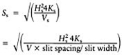
S s=maximum effective length of slits in min;
H s=total depth of permeable fill within slits, in mm;
K s=hydraulic conductivity of the permeable fill (sand, gravel or sand and gravel) within the slit in mm/h;
V s=the overall design rate Fin mm/r, modified according to the ratio of total surface to slit surface as it is only at the slit that infiltration effectively occurs, i.e.
This assumes that the surface is level and the slits are placed close enough to ensure that all surface-ponded water finds its way rapidly across the sward to the top of the slits.
Three-tier systems
For a drainage scheme, involving slits, gravel channels and pipes the notation should read:
S s or S c=maximum effective length of slits or channels between outfalls to next lower tier of underdrainage in mm;
H or Hc =total depth of permeable fill within slits or channels, both in mm;
K s or K c=hydraulic conductivity of the permeable fill (sand, gravel, or sand and gravel) within slits or channels in mm/h;
V s or V c=the overall design rate V in mm/ h, modified according to the ratio of total surface to slit or channel surface.
Gravel-rafted schemes with clearance to pipe underdrains
In gravel-rafted schemes the hydraulic conductivity of the whole of the topsoil superimposed on the gravel bed (including any blinding layer) should in no part be less than the desired overall design rate. Thereafter, the calculation required for specifying the nature of the gravel, the thickness of the gravel bed and the spacing of the pipe underdrains is similar to that described for one-tier systems above, assuming that V is the overall design rate and that lateral flow takes place only within the gravel bed.
Gravel-rafted schemes clearing to four sides of a square
Where the design allows for pipe drainage to be restricted to a peripheral system around the four sides of a flat square, e.g. a bowling green draining freely down into a gravel drainage bed, lateral discharge through the gravel bed can take place in four directions, not just the two which up to now we have assumed. As explained in Appendix E, section E.21, the only modification this entails in the simplified Hooghoudt equation is a change in the constant from 4 to 6.79, i.e. equation (E.25) (page 240)
For rectangles other than see squares Appendix E, (E.24) (page 240).
Coping with the problem of slope
In sports-turf constructions a sloping surface may be part of the challenge required by the game, e.g. on golf and crown bowling greens, or may be incorporated in the surface configuration of the site to assist with surface drainage. Drainage through the soil, however, will also be affected, and a basic assumption involved in Hooghoudt's standard formula used to describe this, may no longer apply. The lateral flow of drainage water through the soil may well not take place horizontally, discharging uniformly to underdrains in two, or more, directions.
In Appendix E, sections E.22 and E.23, this matter is explored mathematically. The results are applied in Chapter 13 where they have particular relevance to the design of the drainage carpet beneath the sloping surfaces advocated for hard porous pitches; the same would apply for grassed pitches similarly based on a drainage carpet. There will be gravitational enhancement of flow down slope, and with outfalls at both ends, there will remain some possibility of flow in the opposite direction. The result is that the extra distance which some of the drainage water has to travel to reach the down-slope outfall will be more than made good: by the extra gravitational head, and by the increment of flow to the up-slope outfall which occurs when the drainage layer is sufficiently saturated to provide the necessary head.
Though relevant also to the short-distance flow that is required under the irregularly sloped surfaces of golf greens, or the sloping trenches involved in three-tier drainage systems (Chapter 3, page 53), the need to take on the extra difficulty of the calculation, when slope is taken into account, may not be justified. On modest slopes, and over relatively short distances, the benefit of slope, though always positive, will be small and might well be treated as a prudent contribution to a safety factor.
When drainage through the soil is directed down slope there is much to be said for a built-in safety factor. Any failure to adequately clear water through the link into the next lower tier of drainage will carry the risk of drainage water re-appearing on the surface where it builds up by accumulation down slope. On a level surface such a build up would be more evenly spread, minimizing the risk of any artesian effect.
The example in Chapter 13 (page 201), deals with a gravel drainage bed beneath a hard porous surface, sloping uniformly at a slope of 1:90, for 64 m (70 yards) across the full width of the pitch. The aim is to calculate, for a particular gravel, the depth required when the only pipe outfalls run along either side of the pitch, i.e. at the top and bottom of the slope. When the procedure used takes account of the beneficial effect of slope, the estimate is for a depth of 216 mm (81/2 in). This compares with 248 mm (9 in) when Hooghoudt's standard equation is used and no allowance is made for the beneficial effect of slope, i.e. a surplus of 13%. However, when an extra pipe outfall is introduced, halfway down the slope, reducing the flow path between outfalls by half to 32 m (35 yards), the estimate for depth of gravel by either method of calculation is also reduced by half, but the surplus which would be introduced by designing according to Hooghoudt's standard formula would remain at 13%. Thus, when the material requirements are small, as would be the case when just a few gravel channels were required to run with slope rather than an entire gravel bed, and the slope is quite modest, around 1:100, then the simpler procedure, using the standard Hooghoudt formula, will do. Otherwise, the more complicated calculation, described in Chapter 13 and explored more fully in Appendix 5, should be used, and any thoughts about a safety factor then considered separately.
Where there is only uni-directional flow to a single outfall, down slope, there will be no benefit from slope until the extra gravitational head exceeds three times the hydraulic head. To adjust for uni-directional flow, down slope, Hooghoudt's standard equation can be used in the modified form
where L is the length of the path through the medium controlling flow in one direction, downslope, and G is the extra, gravitational head resulting from slope. The need to use this modification of Hooghoudt's standard equation seldom arises, but when the conditions apply, it certainly should be used.
Using the simplified Hooghoudt equationto determine S, H, K and V
For drainage through the whole topsoil
Use the simplified Hooghoudt equation in the most appropriate of the following rearranged forms:
where S is the drain spacing in mm, H is the depth to impermeable layer in mm (usually depth of topsoil), K is the hydraulic conductivity in mm/hr for the soil layer through which excess water is free to drain laterally to the pipe system (usually just the topsoil).
For drainage through slit systems
The simplified Hooghoudt equation now takes the form:
Use an appropriate version of the above, or the same general equation re-arranged in one of the following forms:
where S g is the slit length between pipes in mm, H s is the slit depth in mm, K g is the hydraulic conductivity of slit fill in mm/h, V is the overall design rate in mm/h, V g is the overall design rate modified for transmission only through slits.
Implications inherent in the simplified Hooghoudt equation
When seeking to upgrade a drainage scheme there is sometimes a choice between: shortening the interval between pipes, so shortening slit (or gravel channel) length; increasing slit (or gravel channel) depth; changing the particle-size grading of the backfill so as to increase its hydraulic conductivity; or increasing the capacity of the slits (or gravel channels) by increasing their width. From the form of the relationship between these variables, as shown in the simplified Hooghoudt equation, change in one does not necessarily ensure a directly proportional change in any of the others.
Thus, from the equation in the form
reducing the pipe spacing by half, i.e. halving the length of the slits S g, will allow the possibility of halving slit depth H s as this, though within the square root bracket, is itself a squared factor. However, if the change is to accommodate a change in any of the other, unsquared factors—K s, V, slit spacing or slitwidth—then halving S s or doubling H s will allow a four-fold reduction in K s or slit width, or a four-fold increase in V. Slit spacing, however, is not so automatically amenable to adjustment. It has been arbitrarily fixed not to exceed lm, by experience, not by calculation.
Similarly, halving V will allow a halving of K or slit width but only a reduction of 1/2 (i.e. 0.71) in Hs or S s.
In practice it is important to recognize that it is modifications in S and H, or S s and H s, that have the greatest influence on the overall design rate V.
4.1.3
Worked examples of basic schemes
Calculations here do not include any adjustment for slope—see page 66—and are based on metric values only.
Pipe drainage only (i.e. one-tier systems)
Example
4.1
Given the minimum acceptable spacing S for the pipe drain laterals is 4000 mm (41/4 yards), the depth of topsoil H is 300 mm (12 in) and the design rate V is 2 mm/h 1/12 what is the minimum hydraulic conductivity required of the topsoil if the watertable is not to breach the surface under the conditions specified? The site is flat and no slit drainage is intended. It may be assumed that the permeable backfill over the pipes will be trench gravel brought through to the surface as blinding sand.
By using the simplified Hooghoudt equation in the form
we have
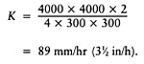
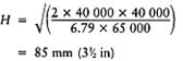
A K value of the order of 75–100 mm/h is unlikely to be sustained by other than a pure sand medium, with all the difficulties this would imply for grass growth. The most that could be relied upon after settlement from either a 3:1 by volume sand/peat mixture (e.g. Table 7.1, SN16), or a loamy sand soil more than 75% medium plus fine sand (e.g. Table 7.1 SN18) would be of the order of 25 mm/h.
What then should be done in the circumstances envisaged in the example? The drain spacing S could be reduced by half to 2 m (61/2 ft) or the topsoil depth H increased to 600 mm (24 in), but these alternatives would probably be unreasonably expensive. Another alternative is to accept a lower standard of efficiency, i.e. accept a design rate V of 1 mm/h, a standard of performance considered satisfactory for agriculture. This would probably be just acceptable for sport in areas of Britain with a relatively low rainfall, e.g. less than 700 mm (28 in) a year.
Changing the soil to a well-structured, granular loam (e.g. Table 7.1, SN21) could provide more than the required hydraulic conductivity K initially but the granulation might well not survive a winter of stud wear, and sand slitting would then be essential.
Generally, if drain spacings closer than 4 m (41/4 yards) are required, a two-tier system is more economical, using close-spaced sand or sand/gravel slits to intercept and then discharge excess surface water into the permeable fill of the trenches that carry the more widely spaced under drains (see Example 4.2 below).
Theoretically at least, there would appear to be scope for the alternative of a miniaturized, one-tier, pipe-drainage scheme. With trenchless machinery, suitably modified to bury small bore, perforated, plastic pipe into narrow 20–40 mm (l-l1/2 in) slits, and simultaneously backfill to the surface with appropriate fine gravel, clean grit or coarse sand, a type of pipe-assisted slit system could be created. However, the pipes would have to be very carefully installed so as to maintain flow for distances long enough to justify their inclusion. On a flat site this will involve very accurate grading of trenches to progressively greater depths. On an adequately sloping site, piped slits could be installed at a fixed, shallow depth of 250–350 mm (10–14 in) from the surface and, if oriented diagonally across slope, these will function for interception and discharge. But, in either case, the pipe being so small and the runs so relatively long, the very accurate grading required will make laser control of trench depth essential. The pipe performance data in Table 2.1 indicates that continuous runs of the order of a pitch length and more are possible. In these circumstances the permeable fill in the trench has only to allow the intercepted water down to the pipe. Virtually any clean sand could achieve this at an overall design rate of 2 mm/ hr 1/12 and a slit spacing to slit width ratio of 36:1, or less.
Example
4.2
What permeable backfill would be appropriate for piped slits, 35 mm (l1/2 in) wide, spaced at 1 m (1 yard) intervals, and required to transfer water from the surface down to the pipe at an overall design rate of not less than 2 mm/h 1/12?
The hydraulic conductivity required of the permeable fill is
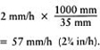
This could be provided even by clean, very fine sand. However, such a sand could infilter the pipe perforations and would also be capable of ingestion by earthworms. It would be better, therefore, either to place trench gravel immediately over the pipe, followed by blinding sand through to the surface, or filter-wrap the pipe and then backfill with blinding sand only.
Pipe drainage augmented with slit drainage (i.e. two-tier systems)
Where the design of a drainage layout is planned to include surface interception by slit drainage, the drainage rate must be calculated separately for each tier of the system, working always from the surface downwards.
It should be recognized at the outset that it is not possible to put a firm figure on surface flow as this depends on surface conditions of smoothness, gradient and grass cover. However, experience suggests that slits should be spaced at intervals of the order of 1 m (1 yard) across slopes of the order of 1:100.
Note, it is only when the drainage water has entered the slit system that the calculations involving the simplified Hooghoudt equation really apply. As in Example 4.2, calculations for a slit system assume that the surface water arriving as rain over the whole playing surface will be concentrated at the slits, according to the ratio of total surface to slit surface.
Example
4.3
If required to cope with rainfall of 2 mm/h (1/2 in/h) what would be the maximum slit length between pipes for two-part, sand over gravel slits, spaced 1000 mm (39 in) apart, 50 mm (2 in) wide, 360 mm (14 in) deep, filled with 180 mm (7 in) of blinding sand (K=500 mm/hr) over 180 mm (7 in) of trench gravel (K=65 000 mm/h)?
Use the simplified Hooghoudt equation in the form
Step 1: the average K a for the two-part, sand over gravel slits
Note, the hydraulic conductivity value K s used to represent the combined effect of the sand and gravel layers in the slit will be the average value K a which has been weighted according to the depths and K values of the two materials concerned (see back to page 64).
Step 2: the overall design rate V, representing the rainfall the system as a whole is required to discharge, must be adjusted to take account of the fact that all runoff is assumed to be concentrated into the slits (see back to page 68).

Step 3: to determine the safe slit length between pipe trench outfalls use
which gives
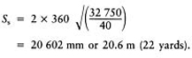
Using Stewart zone materials (Chapter 4, page 62 and Chapter 7, pages 114–117) it is sufficient to take account only of the depth of the trench gravel layer. In a standard slit system, where slit spacing (e.g. 1000 mm) does not exceed more than 20 times slit width (e.g. 50 mm), every 1-cm depth of a trench gravel will safely provide for a minimum of a 1-m increment in the run of the slit between the intercepting pipe underdrains. In the above example, therefore, if the gravel used in the slit had fallen well within the finer half of the trench gravel zone, the 18-cm depth would have allowed the slits to run for a safe distance of 18 m between the relieving system of pipe underdrains at the 2 mm/hr design rate given.
This suggests a simple scheme of pipes at about 20 m intervals crossed at right-angles by sand/gravel slits at 1 m intervals.
Variations
1.If the slit is widened to 75 mm (3 in), V s changes by a factor of 50/75 and S s by -7(75/ 50). Hence the maximum slit length becomes
2.If the original slit is filled with 360 mm (14 in) of blinding sand only (Ks=500 mm/h) the maximum slit length becomes
This shows why slits most often are filled with two materials—sand over an appropriate gravel. The sand contributes little to the discharge capacity of the slit; none the less its presence is essential to allow the gravel to be placed well below the surface where it is less vulnerable to earthworm activity and other forms of soil disturbance. A purpose-made hopper, capable of backfilling simultaneously with two different materials, to two fixed depths, is an obvious practical asset.
3.If the overall depth of the 50 mm (2 in) wide slits is reduced to 250 mm (10 in) and each layer within it (sand over gravel) is reduced in depth to 125 mm (5 in) then the maximum slit length, which was 20.6 m, becomes
i.e. S s is reduced directly in proportion to the change in slit depth.
By the Stewart zone approach, 12.5 cm of a trench gravel such as SN7 in Table 7.1 would allow a safe slit length of 12.5 m between pipe trench outfalls.
This example shows how a change in depth (being a squared factor) has a greater effect on maximum slit length (in this case drain spacing) than an equivalent change in slit width or the hydraulic conductivity of the permeable fill (refer back to page 68).
Pipe drainage augmented with gravel channels and surface slits (i.e. three-tier systems)
Under normal circumstances three-tier systems are not likely to be a first choice on a natural site. However, these may evolve, as in the following examples.
- On an established site where a deep system of field drains already exists and contact with the permeable fill over the pipes may not be readily achieved by a simple system of sand/gravel slits. This could be because of the unsuitability of the fill over the pipes or the presence of obstacles to narrow slitting in the soil at 150–300 mm (6–12 in) from the surface.
- On a tip site where the buried rubble has been covered by less than 250 mm (10 in) of stone-free topsoil and there is uncertainty over the extent to which the rubble fill will act as an effective soakaway. Because of the nature of the rubble fill it may well be necessary to use a large hydraulic excavator to dig out trenches and, if this cannot be done neatly or without great difficulty, it may be desirable to keep the number of pipe underdrains to a minimum.
In a three-tier system the extra tier, the gravel channels, is required to intercept the surface tier of slits at the limit of their effectiveness, and then link across to the pipe underdrains. Gravel channels of this type are likely to be at least 150 mm (6 in) wide, but their permeable fill need not be taken through to the surface as surface infiltration will already be adequately covered by the slit system.
If necessary, consideration can be given to increasing channel width to compensate for any limitation in depth. However, as H is a squared factor in the simplified Hooghoudt equation, a reduction by half in the depth of the gravel channel will involve a reduction by half in its hydraulic capacity and will require a fourfold (i.e. 22) increase in channel width to compensate.
Careful attention to the grading of the permeable fill will be necessary, above and below: above to avoid loss by infiltration into large cavities within the underlying rubble (or the backfill of the pipe drain); below, to prevent infiltration of soil used to cap the surface.
Example
4.4
Sand slits are required to clear surface water at 2 mm (1/12 in)/h through a level, slow-draining but easily trenched, stone-free topsoil, 200–250 mm (8–10 in) deep. However, the topsoil rests on a compact foundation of stony, tip waste which becomes progressively more difficult to trench with depth. What system of intercepting gravel channels and pipes could be organized to complete the job of drainage, keeping deep trenching to a minimum?
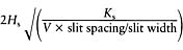
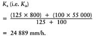
Step 1: the initial tier of surface slits might be, for example, 50 mm (2 in) wide, 225 mm (9 in) deep, at 1 m intervals, filled first with a 100 mm (4 in) layer of trench gravel (K=55 000 mm/h) and topped up to the surface with a 125 mm (5 in) layer of blinding sand (K=800 mm/h).
To achieve a design rate of 2 mm (1/12 in)/h such a system of slits would require relieving into a second tier of drainage channels at intervals determined by the hydraulic conductivity K s of the sand/gravel slits:
We can then go on to determine slit length Ss which will also be the spacing of the gravel channels if they intersect at right-angles:
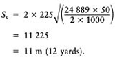
Note, for the purpose of this example a particular 10 mm gravel, currently available in mid-Wales, has been cited because the particle-size composition and hydraulic conductivity are known. This material, precisely defined in accordance with the guidance given in Chapter 7, is 10 mm, rounded but somewhat platey gravel; D 15=2.8 mm, D 85=8.9 mm, i.e. 70% of the particles, excluding 15% at either extreme are 2.8–8.9 mm in diameter; and K (the saturated hydraulic conductivity)=55000 mm/h. However, had another 10 mm gravel, known to be available in the south of Scotland, been used, the slits could have been allowed to run 22 m (24 yards) between the gravel channels. This other material, precisely defined, is 10 mm, single-size rounded gravel; D 15=5.8 mm, D 85=9.8 mm, K=225 000 mm/h, i.e. a material with 70% of its particles within the range 5.8–9.8 mm. Clearly it is very important to define materials used in drainage work more precisely than simply to quote the sieve size through which all the material has passed (Chapter 7).
Using the Stewart zone approach, the incremental allowance per cm of gravel in the case of the first gravel used, a gravel wholly in the finer half of the trench gravel zone, would be 1 m. Hence the 100 mm (4 in) layer of gravel in the slit would be estimated to allow for slit runs to underdrain outfalls of the order of 10 m long (compare the 11 m by precise calculation). For the second gravel, a material wholly in the coarse half of the trench gravel zone, the increment per cm of gravel would be 2 m. This would allow an estimate for slit runs of 20 m (compare the 22 m indicated by precise calculation).
Step 2: the medium immediately beneath the layer of superimposed topsoil on a tip site may have to keep the topsoil from seeping down into the large rubble below. Such a layer may contain numerous small stones making it difficult to slit but readily dug out by the narrow, tapered bucket of a hydraulic excavator. Thus gravel channels may be installed through the intermediate, blinding layer of stony soil, say 200 mm (8 in) wide and as deep as the larger rubble will allow efficient excavation, say 375 mm (15 in) deep. The backfill will then have to take account of the nature of the exposed rubble and the need to form a clean link to the gravel layer at the base of the slits, say a backfill of trench gravel taken to within 125 mm (5 in) of the surface, then 25 mm (1 in) of blinding sand and the remainder, soil.
To maintain the overall design rate of 2 mm (1/2 in)/day, such a channel system, unless able to soak away efficiently into the rubble, will require relieving into a third tier of pipe underdrains. As the pipes will have to be inserted into the least hospitable part of the tip rubble, where trenching may be particularly difficult, the aim should be to maximize the length of the gravel channels so as to keep the requirement for pipes to a minimum.
In this example the gravel channels envisaged would require the pipe trenches to be spaced at no more than 11 m (12 yard) intervals:
This of itself achieves no benefit over a two-tier system of slits delivering to pipe drains at 11 m (12 yard) intervals, except that the gravel channels are effective within their limits when laid flat, whereas the pipe runs have to be graded progressively deeper into tip rubble. To be economical on deep pipe trenching, therefore, the middle tier of pipeless channels must deliver at the required design rate over a much wider spacing than the 11 m calculated for the channels cited above.
To treble the spacing of the pipes the options are:
- multiply the channel width by 32, to 1800 mm, but this would be ridiculous;
- multiply channel depth by 3, to 750 mm, but this could be difficult if the bottom of the trench had to be cut through the tip rubble;
- reduce the design rate by one-ninth, to 0.22 mm/hr, but this would then be inadequate for winter use;
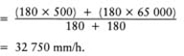
- multiply the hydraulic conductivity of the channel fill by 9 for the bottom 150 mm (6 in) of its depth, e.g. by changing this to a single size, 20 mm (3/4 in), small to medium stone (K of the order of 900 000 mm/h).
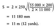
To verify option 4 calculate first the hydraulic conductivity of the two-part gravel/small stone fill in the channel:
Then, calculate the maximum length of run for the gravel/stone channels between pipe runs:
This reduces the requirement for deep trenching considerably, making option 4 a good proposition
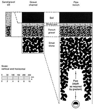
FIGURE 4.2 Trench dimensions and backfill for a three-tier system.
for meeting the requirements of this difficult site. Figure 4.2 summarizes the trench systems involved.
These calculations are inappropriate for the much simplified Stewart zone approach as (a) the main material in the channel, responsible for discharging water laterally is not a trench gravel, and (b) the trench width to channel spacing ratio is 1:55 which far exceeds the 1:20 ratio of a standard slit system.
If the tip is naturally or artificially drained at depth there may be no need for any third tier of pipes, but then either the slits or the gravel channels will have to be organized to discharge at intervals into the underlying rubble. Blinding may be necessary to keep the channel fill from leaking away into the rubble.
Gravel-rafted schemes, generally for fine-turf surfaces
Where a freely permeable, sandy topsoil is laid over a drainage bed designed to do the entire job of lateral discharge to underdrains, the sandy topsoil has only to allow the incident rain water to drain vertically through to the gravel bed at the overall design rate V. However, in a layered construction it will be the hydraulic conductivity of the least efficient layer that will be the rate-limiting bottleneck, particularly a junction between layers where particles of different size are free to interpack. In time, also as the sward develops, organic matter, living, dead and decaying, both within and on top of the soil, will further modify performance. All this is difficult to predict theoretically, even for the initial, raw state.
Not only has the hydraulic conductivity of the different layers and layer boundaries to be considered however; we also need to know the extent of the effective head. At saturation this will not correspond just to the thickness of the layer itself but will extend both above and below into all layers that are effectively saturated.
Field checks on infiltration rates would seem to be the answer, but these are difficult to perform satisfactorily and, by the nature of things, can only be done after construction.
As general guidance, it would be worthwhile to assume that without worm activity to continually re-structure the soil for drainage, even a sand soil is unlikely to achieve an infiltration rate more than 25–50 mm (1–2 in)/h when maintained under grass. However, even a value of 2 mm/h (2 in/day) would be enough to achieve the minimum overall design rate normally found adequate in Britain for general sports turf, but is close to the rate required when the runoff is all concentrated into the sand at the top of sand slits.
For most sports we can make supplementary provision to cope with short bursts of intense rain by contouring the surface to clear excess surface water down slope to the periphery. By contrast, on a flat surface, we must work to maintain the initial infiltration of the raw surface by regular, sand topdressing, spiking and coring so as to make full use of the sand topsoil's own capacity for temporary storage.
To determine the hydraulic head likely to be effective at the surface in such a layered construction, account should be taken of the depth of the coarse sand forming the blinding layer as well as the depth of the fine sand forming the topsoil. However, only if the effective pore systems of the two materials are similar in size, or the pores in the blinding layer are smaller, will they behave as one when wetted from above. If the effective pores in the binding layer are large compared with those in the fine sand, then only after the fine sand has been more or less saturated will water be shunted through into the blinding layer. Similarly the blinding layer will have to be more or less saturated before it in turn will release water to drain away through the much larger pores in the underlying gravel drainage bed.
After any initial phase of relatively rapid soil water re-distribution and drainage through the bulk of the pore space itself, there is still the possibility of further adjustment by the much slower process of water movement through continuous films of water that creep over surfaces and cling tenaciously around individual particles. No doubt this also accounts for the slow rate of further drainage that can be observed to continue for many days after any initial phase of rapid drainage has ceased.
For the sake of cost the depth of the gravel bed should be kept to a minimum, but so also should the amount of pipe work. The balance struck will depend on the relative cost of the two features concerned.
Example 4.5
An organic-ameliorated, sand topsoil laid over a bed of trench gravel might have a K value between 2 and 20 mm/h Suggest a suitable depth for the gravel bed to clear drainage water to pipe underdrains restricted to the periphery of a 40 m square, e.g. as for a bowling green. Assume the depth of the gravel bed is to be (a) restricted to 100 mm, (b) can exceed the 100 mm restriction. Compare for each case the effect of targeting overall design rates at the two extremes of 2 and 20 mm/h.
A suitable spacing for the pipe trenches can be determined by using the simplified version of Hooghoudt's drain-spacing equation
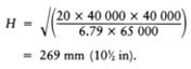
Substituting 100 mm for H, 2 mm (or 20 mm) for Fand 65 000 mm/h as the K value for the typical trench gravel:
or
A suitable depth for the gravel bed when pipes are to be confined to the periphery of a square bowling green can be determined by using an appropriately rearranged version of the simplified Hooghoudt equation and a change in the constant from 4 to 6.79 (refer back to page 66). This will take account of the freedom in the situation for drainage water to clear in four directions instead of just two. Thus,
Substituting 2 mm (or 20 mm) for V, 40 000 mm for S and 65 000 mm/h for K,
or
To achieve the 20 mm/hr design rate with a drainage bed only 100 mm deep would require the introduction of some stone. This will greatly increase transmission, but must do so without risk to the stability of the layers above, e.g. small to medium stone, K=900 000 mm/h. (Chapter 7, pages 126–127 gives information on selecting materials likely to remain stable in a layered sequence.)
To calculate the effect of forming the drainage bed of 50 mm of small to medium stone covered by 50 mm of trench gravel, proceed as follows.
Step 1: for the averaged hydraulic conductivity required of the new drainage bed
Substituting what we know,

Step 2: we also know that
Substituting what we know,
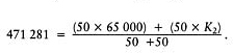
Therefore the hydraulic conductivity K 2 required of the 50 mm layer of small to medium stone can now be calculated as K 2= 877 562 mm/h.
This is a K value very close to the 900 000 mm/hr quoted for a small to medium stone referred to previously, page 73.
Note, it would not be wise to assume that if a particular small to medium stone is adequate to achieve the desired objective, an even bigger stone would be better. Too big a stone would allow the gravel above to interpack, dramatically reducing the effectiveness of the two materials organized as a stable, two-layered system.
The soil base of a gravel drainage bed might well slope slightly to assist the flow of water towards the pipe underdrains. A flat base would tend to lie wet and locally puddled. For designs of this nature, those suggested for hard porous pitches (Chapter 13, section 13.3).
4.1.4
Two examples of practical circumstances justifying modification of standard schemes
Slope
Slope requires special consideration as the steeper the gradient the faster the runoff of surface water after rain. When the simplified Hooghoudt equation is applied to the slit situation it is assumed that excess surface water will mainly reach the slit by unimpeded flow over the surface. However, surface flow is bound to be much more effective on land with an appreciable slope. Hence there is a case for spacing the slits slightly more widely apart on slopes of the order of 1:50 or more, provided the slits run horizontally across the slope.
Availability of materials
A factor about which a designer must be particularly careful is the availability of materials. Theoretical calculations are of little value if the sand and gravel materials specified cannot be supplied, or are only obtainable at a cost far in excess of what the client can afford.
For efficient drainage we need to make use of materials that remain open, even when close-packed. Ideally, this means materials made up of rounded particles, all one size. However, the major users of sands and gravels are the construction industries and they are often looking for materials that will inter-pack to achieve maximum density. Before proceeding to calculations, therefore, it is important that the designer should first ascertain what is the range of materials at his disposal. Where, for tendering purposes, materials have to be specified in advance, the contractor should be made aware that use of a different material to that specified may necessitate a change of layout. (Chapter 7 gives further information on the selection and specification of sands and gravels used in the construction and drainage of sports turf facilities.)
4.2
Absorption and retention of water
4.2.1
Theoretical considerations affecting design calculations concerned with capillarity and critical tension
Demonstrations
To understand how water is absorbed, retained and cleared by a porous medium such as a soil, we need to have some understanding of the twin phenomena of capillary rise and critical tension. These are difficult to describe simply but can be demonstrated by the sequence of procedures illustrated in Figure 4.3.
For the experiments illustrated in Figure 4.3 (a.i—vii), the sand-filled glass tube is best made up initially of particles all of just one particle-size grade, e.g. all fine or all medium sand, and the base closed over with a small piece of finely woven, cotton cloth, secured with an elastic band. For fine sand the sand column should be approximately 400 mm (16 in) deep, and the tube some 200–300 mm (4–6 in) longer. For medium sand these dimensions could all be halved.
Lower the sand-filled tube into a reservoir of water, holding it upright and keeping the cloth-covered base just below the surface of the water. Observe how the water is drawn up through the sand column by capillarity, then proceed to explore the related phenomenon of critical tension.
For the experiments illustrated in Figure 4.3 (b.viii–xiv) it is necessary first to determine the critical tension of the foam sponge used so that the two strips required for the demonstrations that follow can be cut to the appropriate size and shape. Then explore how water can be retained or drained according as the two strips are organized.
A soil, saturated to the surface, may still allow additional water to infilter so long as an equivalent amount of water can be cleared out below to a drainage outfall. It is the rate of this saturated flow with which Hoogboudt's simplified equation is concerned (Chapter 4, section 4.1). However, having allowed additional water to be shunted through the water-filled pore space, the soil may not be able to complete the job of drainage by finally emptying the pores to admit air.
The transmission of water is only one aspect of drainage which, when it ends, may still leave the transmitting pore system completely water-filled. This can be demonstrated by the procedure illustrated in Figure 4.3 (a.v.4) and (a.vii.6). Note, the column of saturated sand will transmit additional water—one drop in being matched by one drop out—but there is no further drainage thereafter. Even spiking is ineffective unless, for some reason, particle segregation, organic accumulation, or inappropriate topdressing has led to the creation of a fine-textured cap. (See Appendix 6 and Figure 4.3 (a.vii).).
The water held up in a perched watertable is under tension, unlike water within a ground watertable. As indicated in Figure 4.3 (b.ix, xii and xiv), however, it is this tension which provides the ‘draw’ that can be organized to assist drainage. Note the draw does not originate in any underlying pipe but in the perched watertable that can be organized in the trench fill above.
Theory
Wetting up from below is very effective—some might say too effective in that air will be readily displaced upwards, ahead of the rising water front—leaving the soil within the capillary fringe, virtually saturated to the exclusion of air. Unless water, wetting a soil from above, arrives in fine, dispersed droplets the surface will very rapidly flood over. This is because air bubbles have difficulty escaping upwards through a water-sealed surface, and cannot be displaced downwards through a compact subsoil. As a result, because most soils in the field are wetted primarily from above, some air-filled pores are bypassed by the downwardmoving water front. Thus topsoils tend only to become completely waterlogged when wetted from above if this trapped air is subsequently dislodged by the puddling action of wheeled traffic, or spiking treading.
Water is a polar liquid, i.e. the water molecules are charged both positive and negative, like little magnets, and thereby cohere to each other and adhere to the similarly charged surfaces of soil minerals such as quartz, or glass. This coherence also allows water to have a certain tensile strength when suspended as a drop or extended into a fine, capillary-sized thread. It is the attraction of water to glass that holds a raindrop to the vertical face of a glass window until it is unstabilized by vibration or increasing weight. It may then slip down over the surface but will still remain a coherent droplet, attached at one side.
Close examination of the surface of the water around the edge of a glass shows how the attraction of the glass raises the level of the water all around the rim. Now imagine the glass progressively reduced in diameter to a hair-like, capillary tube open at either end, the lower end immersed in a basin of water. The surrounding glass surface would then be large compared with the contained volume so that water, free to move, will be drawn some distance up the tube, like water into blotting paper. It is this process that enables water to be drawn up through sand from a free-water reservoir until the attractive force (the pull) is balanced by the weight of the suspended water column (Figure 4.3 (a. iv)). The finer the capillary system the stronger the influence of the particle surface over the water contained within it and, therefore, the higher the water can be raised. In section 4.2.2 this relationship is more fully explored by means of a formula which enables the extent of capillary rise to be predicted when the diameter of the capillary pathway is known.
In a capillary tube the length of the fine, water column that can be suspended is not affected by whether the water arrives from above or below, provided air can be displaced to make room for it. However, in a uniform particle-size sand, for example, though the surface to void ratio in the pore system may ensure some positive capillary effect, the pore system is not strictly tubular. The simplest such system would consist of closely packed uniform diameter spheres in which open cavities would be joined through funnel like necks in a regular sequence, as illustrated in Figure 4.4.
The diameter of a spherical particle that could just fit into the cavities within such a system would be a little under half (0.42) particle diameter, and the diameter of spherical particles that could just fit the necks would be one-seventh (0.14) particle diameter. Water lifted by capillarity through such a system would be arrested ultimately by the position in which the attracting surface of the particles had their minimum effect, i.e. across the maximum diameter of the highest pore cavities invaded. Water cleared downwards from above, however, would tend ultimately to be suspended from a neck, which is the place where the retaining hold of the mineral surface on the water column is likely to be most effective. Thus, as comparison of Figure 4.3 (a. iv) and (a. vi) indicates, a water front lifted by capillarity from below will rise to approximately half the height to which water will be held up after drainage has ceased following flooding, i.e. capillary rise will always be less than critical tension.
In a natural sand, complications may arise, not only because of air entrapment, but also because the geometrical relationships described above will be modified by variations in particle-size, shape and packing. In Figure 4.3(c) note how the variations in pore size which are liable to occur in a heterogeneously packed, narrow mixture of particle sizes results in the degree of saturation steadily falling off with increasing height. Also, the strength of the attraction between the mineral particles and the water may be modified by impurities in the water and coatings on the particles affecting wettability (Thornton, 1978, p. 501). Hence, predictions based on the simple relationships in the calculations that follow (section 4.2.2) are probably exaggerated, and should never be considered more than approximate.
As in a sand, the amount of water retained in a normal soil after drainage has ceased will depend on the initial state, and which way the soil has been watered. A dry soil, with a water-stable granular structure, when wetted quickly from above, will tend to allow much of the water to fall freely under gravity. This will descend rapidly through the inter connected system of very large pores between the soil granules, air being simultaneously displaced upwards. Thereafter, re-distribution will take place under the control of capillary forces into the fine pores within the granules, but again, only if air can be displaced. However, if mechanical smearing creates a cap of destructured soil at the surface, this fine-pored
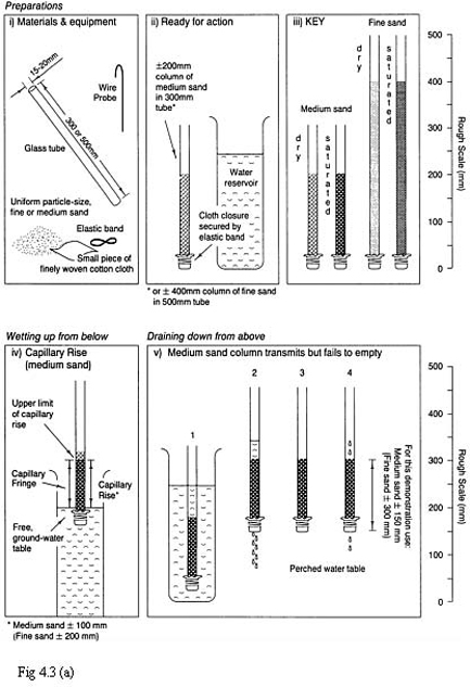
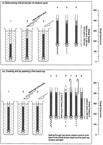
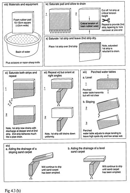
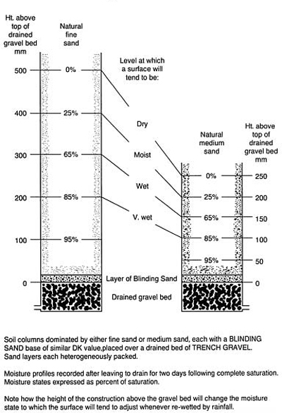
FIGURE 4.3 Demonstrating capillary rise and critical tension, (a) Using columns of uniform, artificially graded sands, (b) Using foam-rubber sponges to simulate soil. Moisture profiles for (c) natural sand soils rafted over gravel. Soil columns dominated by either fine sand or medium sand, each with a blinding sand base of similar D, value, placed over a drained bed of trench gravel. Sand layers each heterogeneously packed. Moisture profiles recorded after leaving to drain for two days following complete saturation. Moisture states expressed as percentage saturation. Note how the height of the construction above the gravel bed will change the moisture state to which the surface will tend to adjust whenever re-wetted by rainfall.
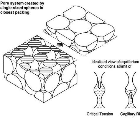
FIGURE 4.4 (a) Three-dimensional drawing to show pore system created by single -sized spheres in closest packing. Note the continuous hexagonal formation, (b) Idealized view of equilibrium conditions within the pore system at critical tension and at the limit of capillary rise.
barrier will hold on to the water it absorbs, and will impede further infiltration by obstructing the release of the trapped air.
Only an uncapped, worm-worked soil will maintain the wide range of pore sizes, that allow for the air release required to ensure the rapid infiltration and re-distribution of rain-water necessary for an efficient moisture regime. All soil reacts best to the farmer's fine, wetting rain, rather than the same amount of rain in intense, short bursts. Heavy rain may physically degrade a mechanically formed structure and immediately flood the surface, trapping air below. This impedes infiltration so that water accumulates above ground while runoff over the surface threatens to cause erosion.
4.2.2
Calculating critical tension from information on particle size
Critical tension can be determined practically but it is probably more convenient to make an estimate based on the formula used to estimate the capillary rise of water in uniform diameter capillary tubes. This process is described by the equation
where h is the height of the water column in cm, T is the surface tension of the water (75 dynes/cm), g is the acceleration due to gravity (approximately 1000 cm/s/s), D is the density of water (1 g/cm3) and r is the radius of the water-containing pore in cm.
As T, g and D can all be considered constant, and with all measurements expressed in centimetres, the equation reduces to
But, as the initial information which we want to use is concerned with particle size, not pore size, the equation must be adjusted to take this into account. We can do this by using the information that, for a uniform set of spheres in closest packing, pore radius is approximately 0.21 times particle diameter. Thus, assuming that silt and sand particles attract water similarly to glass and are roughly spherical in shape, the equation, expressed in millimetres, becomes
The form of this equation suggests that critical tension is inversely proportional to particle diameter so that doubling the particle size will halve the critical tension. Thus, the critical tension for fine sand of uniform, 0.2 mm particle diameter, should be approximately 71.4/0.2=357 mm (14 in); a medium sand of 0.4 mm particle diameter would be expected to have half the critical tension of fine sand, i.e. 178 mm (7 in).
As critical tension is controlled more by the necks of the pore outlets than the pore itself these values could be looked upon as likely to under-estimate the true value. However, because of particle surface limitations on the efficiency of wetting, and the state of closest packing being seldom fully achieved in the field, theoretical values may well exaggerate the field response.
Very few commercially available sands are likely to be of single particle size, but when adequately mixed, can be assumed to behave in accordance with the particle size of the finest group of particles that come to dominate the pore space by interpacking. As this is true also for hydraulic conductivity we can hope to develop a system for predicting both, based on the idea of the dominating, or effective particle diameter (D 15, D 25or D 35). Such a system is described in section 7.1.8, and has been used in Table 7.1 to predict values for hydraulic conductivity and critical tension (refer also to Figures 7.7 and 7.8).
4.2.3
Practical application of theory to problems of the absorption and retention of water
Combining rapid drainage with adequate water retention
A fine pore system will tend to abstract water from a large pore system. For this reason, a sand layer blown over a freely drained, fine-textured soil will tend not only to lose excess water by drainage to the soil below but, as the fine soil itself drains, so it will tend to draw out capillary-held water from the coarser-pored sand.
However, the ability of a sand to hold on to a store of water, at least to the extent of its effective critical tension, can be induced by establishing a horizontal capillary break between the sand top and the fine soil below. This can take the form of an air lock created by draining an underlying, coarser pore system, e.g. a drained gravel bed. Thus a 300 mm (12 in) layer of fine sand can be organized to store 90 mm (31/2 in) of water, i.e. a fortnight's supply of water for vigorous grass growth in mid-summer or a 3–4 week buffer against death by desiccation. Note, this perched watertable will clear downhill if the interface forming the capillary break is inclined on a slope (Figure 4.3 b. xiii and b. xiv).
Because of capillarity a soil can be watered from below without raising the watertable to the surface, e.g. by using a sub-irrigated bed of gravel to maintain a free water source in continuous contact with the base of the soil. But if the base of the soil is compact and very fine in texture, as would necessarily have to be the case on a cricket square, the rate of wetting up through the capillary pore system could be frustratingly slow. A sand soil is nothing like as slow to wet up by sub-irrigation and is also effective for surface irrigation, discharging excess water through the gravel bed only after replenishing the reserve capacity of the sand layer.
For a sand soil constructed over a gravel drainage bed there appears to be a range of soil depths over which grass may perform satisfactorily after successful establishment. Thornton (1978, pp. 526–527) concluded, after careful monitoring of similar sets of differently constructed field plots located at four main centres in England and Wales, that construction down to a depth of sand, approximately half the laboratory-determined value for critical tension, was justified. However, he also found that grass performance was no less good at the full critical tension depth. To explain the absence of poor aeration in the top 100 mm (4 in) of the soil, even at the shallower soil depth, he draws attention to the possibility that variations in the efficiency of air displacement could arise from variations in wettability, according as the sand particles are coated, e.g. with a film of iron oxide or protein. Alternatively, it could be that re-distribution of water under capillary forces following any initial wetting (as discussed in section 4.2.1, page 85), may lead to an equilibrium moisture profile more in line with expectations based on capillary rise rather than critical tension.
However this may be, the practical evidence seems to support the idea that the construction depth for a sand soil, perched over a gravel drainage bed, should neither be more than the critical tension nor less than half. Any blinding layer required beneath the sand soil should be included within this depth if the Dk values are similar, indicating that the pore systems present in both layers are likely to be compatible, i.e. similar in diameter (page 119). At the full critical tension extreme, the surface may tend to dry out so rapidly that it will require repeated irrigation to remain sufficiently moist for seed germination but, thereafter, should encourage deeper rooting unless transformed by thatch development. At the shallowest extreme of half the critical tension, the surface should more readily remain moist enough to encourage rapid seed germination but, thereafter, the grass may tend not to root as deeply, and there may be a greater risk of invasion by weeds, moss and disease. For a fine sand soil this points to an optimum range of between 250 and 300 mm (10 and 14 in) for the consolidated sand soil over the top of the gravel drainage bed.
At the low concentrations of organic matter or mineral soil amelioration used in sand soils we can assume heterogeneous packing and that the top as a whole will behave in a manner controlled by the sand. Any localized concentrations of organic matter, or fine particles of soil, will exert their own greater tendency to hold on to water, acting as local reservoirs outwith the general situation dictated by the sand. However, should the different materials segregate with agitation during placement, some form of layering may develop subsequently through downward migration and redeposition of silt and clay. It will then be the fine pore system in the deposition layers that will control the downward clearance of water and provide localized, potentially anaerobic barriers to root penetration.
Counteracting risks of desiccation
When sand rests directly on soil, as in the case of a construction involving a surface carpet of sand, it should be appreciated that a freely drained soil at field capacity behaves as if it is equilibrated at a tension of the order of 1000 mm (40 in). The soil under the sand, therefore, will tend to withdraw water from the surface layer of sand. This means that the grass should be encouraged to root through into the underlying soil to acquire an assured water supply. For this reason, the sand carpet should not exceed 150 mm (6 in) in depth and due regard should be paid to the fertility of the buried soil before covering it. It also explains why subsequent maintenance should aim to avoid any surface accumulation of organic debris or applied phosphate, both of which will encourage surface rooting.
For a similar reason, sand in slits will lose water to the soil with which it is in contact and the establishment of grass along the slit may well be difficult. To minimize this problem consideration should be given to the following features:
- watering the surface by artificial means until germination and establishment has been achieved;
- seeding only in the autumn when weather conditions are likely to be most favourable;
- avoiding unnecessarily wide slits so that the grass can root sideways into the soil;
- topdressing materials, such as grass clippings, moist peat, or seaweed to help retain water near the surface.