
6.2 Spatial audio coding
6.2.1 Concept
The concept of spatial audio coding as employed in the MPEG Surround standard [138] is outlined in Figure 6.1. A multi-channel input signal is converted to a down-mix by an MPEG Surround encoder. Typically, the down-mix is a mono or a stereo signal, but more down-mix channels are also supported (for example a 5.1 down-mix from a 7.1 input channel configuration). The perceptually relevant spatial properties of the original input signals that are lost by the down-mix process are captured in a spatial parameter bitstream. The down-mix can subsequently be encoded with an existing compression technology. In the last encoder step, the spatial parameters are combined with the down-mix bitstream by a multiplexer to form the output bitstream. Preferably, the parameters are stored in an ancillary data portion of the down-mix bitstream to ensure backward compatibility.
The right panel of Figure 6.1 outlines the MPEG Surround decoding process. In a first stage, the transmitted bitstream is split into a down-mix bitstream and a spatial parameter stream. The down-mix bitstream is decoded using a legacy decoder. Finally, the multi-channel output is constructed by an MPEG Surround decoder based on the transmitted spatial parameters.
The use of an MPEG Surround encoder as a pre-processor for a conventional (legacy) codec (and a corresponding post-processor in the decoder) has important advantages over existing multi-channel compression methods.
- The parametric representation of spatial properties results in a significant compression gain over conventional multi-channel audio codecs, as will be shown in Section 6.5.
- The use of a legacy codec with an additional spatial parameter stream allows for backward compatibility with existing compression schemes and broadcast services.
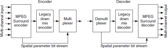
Figure 6.1 Multi-channel encoder (left panel) and decoder (right panel) according to the spatial audio coding concept. Reproduced by permission of the Audio Engineering Society, Inc, New York, USA.
The MPEG Surround coder inherited many of the aspects of parametric stereo, such as the support for dynamic segmentation, the dedicated filterbank and different parameter frequency resolutions. Several new features were developed as well:
- The spatial parameterization enables novel techniques to process or modify certain aspects of a down mix. Examples are matrixed-surround compatible down-mixes, support for so-called artistic down-mixes or the generation of a 3D/binaural signal to evoke a multi-channel experience over legacy headphones.
- The channel configuration at the spatial encoder can be different from the channel configuration of the spatial decoder without the need of full multi-channel decoding as intermediate step. For example, a decoder may directly render an accurate four-channel representation from a 5.1 signal configuration without having to decode all 5.1 channels first.
- To overcome limitations of a parametric model, ‘residual coding’ was introduced to enable MPEG Surround to support a higher quality, approaching transparency.
- A enhanced matrix mode allows for upmixing conventional stereo content to highquality multi-channel signals.
6.2.2 Elementary building blocks
The MPEG Surround spatial coder structure is composed of a limited set of elementary building blocks. Each elementary building block is characterized by a set of input signals, a set of output signals, and a parameter interface. The generic elementary building block is shown in Figure 6.2. An elementary building block can have up to three input and output signals (as shown on the left and right side, respectively), as well as an input or output for (sets of) spatial parameters.
Different realizations of elementary building blocks serve different purposes in the spatial coding process. For example, a first type of building block may decrease the number of audio channels by means of spatial parameterization. Hence, if such a block is applied at the encoder side, the block will have fewer output channels than input channels, and has a parameter output. The corresponding block at the decoder side, however, has a parameter input and more output channels than input channels. The encoder and decoder representations of such an encoding/decoding block are shown in the top left and top right panels of Figure 6.3, respectively. Two different realizations of the encoding/decoding blocks exist. The first realization is a block that describes two signals as one down-mix signal and parameters. The corresponding encoding block is referred to as two-to-one (TTO), while the decoding block is termed one-to-two (OTT). In essence, these blocks are similar to a parametric stereo encoder/decoder [47, 79, 214, 217, 234, 235]. The second realization is a so-called three-to-two (TTT) encoding block, which generates two output signals and parameters from three input signals. The corresponding two-to-three decoding block generates three signals from a stereo input accompanied by parameters.
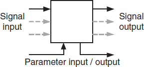
Figure 6.2 Generic elementary building block for the MPEG Surround coding process. Reproduced by permission of the Audio Engineering Society, Inc, New York, USA.
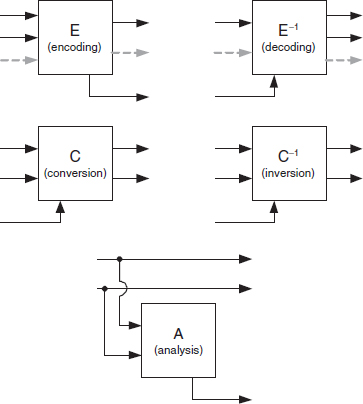
Figure 6.3 Elementary building blocks for MPEG Surround coding process. Reproduced by permission of the Audio Engineering Society, Inc, New York, USA.
A second type of building block is referred to as signal converter. For example, a stereo input signal may be converted into a stereo output signal that has different spatial properties, and of which the processing is controlled by parameters. This is shown by the left-middle panel of Figure 6.3. The corresponding decoder-side operation (as shown in the right-middle panel) inverts the processing that is applied at the encoder to retrieve the original (unmodified) stereo input signal. Examples of signal converters are the conversion from conventional stereo to matrixed surround compatible stereo or to 3D/binaural stereo for playback over headphones.
The third type of building block is an analysis block. This type generates parameters from a signal stream without modifying the actual signals or signal configuration. This block, that can be applied at both the spatial encoder as well as the decoder side, is shown in the bottom panel of Figure 6.3.