
5.4 Parametric stereo encoder
5.4.1 Time/frequency decomposition
The encoder receives a stereo input signal pair x1(n), x2(n) with a sampling rate fs. These input signals are decomposed in time/frequency tiles either using a STFT or by applying a filterbank. When using a STFT, time-domain segmentation and windowing is typically applied prior to transformation to the frequency domain. When a filterbank is applied, windowing and segmentation can be applied in the filterbank domain as well. If the input signal does not contain strong transients, the frame length (or parameter update rate) should match the lower bound of the measured time constants of the binaural auditory system (i.e., between 23 and 100 ms). Dynamic window switching is preferably used in the case of transients. The purpose of window switching is twofold. Firstly, to account for the precedence effect, which dictates that only the first 2 ms of a transient in a reverberant environment determine its perceived location. Secondly, to prevent ringing artifacts resulting from the frequency-dependent processing which is applied in otherwise relatively long segments. The window switching procedure, of which the essence is demonstrated in Figure 5.2, is controlled automatically by a transient detector.
If a transient is detected at a certain temporal position, a stop window of variable length is applied which just stops before the transient. The transient itself is captured using a very short window (of the order of a few milliseconds). A start window of variable length is subsequently applied to ensure segmentation at the same temporal grid as before the transient.
The frequency partitioning is organized in parameter bands. Each parameter band b (b = 0,..., B − 1) represents a certain signal bandwidth for each time segment. The parameter bands closely mimic the critical band concept; at low frequencies, parameter bands are relatively narrow in bandwidth, while at high frequencies, the bandwidth of each parameter band increases.
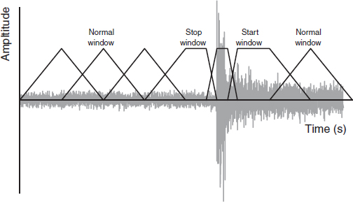
Figure 5.2 Schematic presentation of dynamic window switching in case of a transient. A stop window is placed just before the detected transient position. The transient itself is captured using a short window.
The frequency bands are formed in such a way that each band has a bandwidth, BW (in Hz), which is approximately equal to the equivalent rectangular bandwidth (ERB) [98], following:
![]()
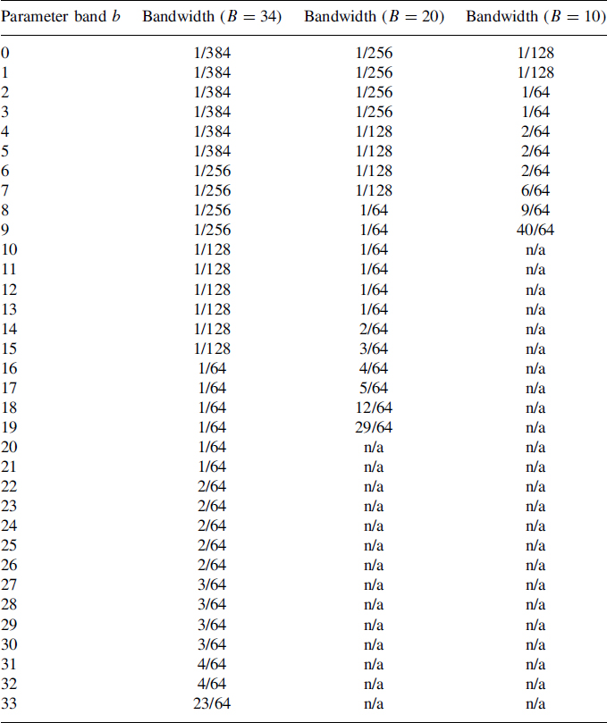
with f the (center) frequency given in Hz. This process results in B = 34 parameter bands. The center frequencies of each parameter band vary between 28.7 Hz (b = 0) and 18.1 kHz (b = 33), assuming a sampling rate of 44.1 kHz. Additionally, two alternative parameter-band configurations are supported with a reduced number of parameter bands (B = 20 and B = 10). The bandwidths (as ratio of the full bandwidth, i.e., half the sampling frequency) of all parameter band configurations are given in Table 5.1.
5.4.2 Parameter extraction
The time/frequency decomposition process resulted in windowed sub-band or transformed signals x1,m(k) and x2,m(k) with m the sub-band index. The sub-band signals m are combined into parameter bands b, for which parameters are extracted. The first parameter is the inter-channel level difference (ΔLx1x2,b), defined as the logarithm of the power ratio px1,mεmb/px2,mεmb of corresponding parameter bands from the two input signals:
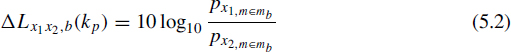
with m ε mb representing all sub-band signals corresponding to parameter band b and kp the temporal parameter position corresponding to the current analysis frame. In the following, the parameter position kp will not be shown, assuming that for each analysis segment, the parameter analysis procedure is repeated. Assuming complex-valued signals (for example resulting from an STFT or complex-valued filterbank), ΔLx1x2,b can be written as
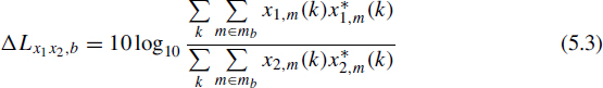
where (*) denotes complex conjugation.
The relative time difference between the channels is presented by a phase angle (inter-channel phase difference, ICPD). The use of ICPD over ICTD facilitates easier analysis and quantization than ICTD, given its limited range of 2π rad. Psychophysical evidence exists that the sensitivity to changes in ITD can be described quite accurately by a constant phase change (see Section 3.5.1) Hence the use of a phase parameter enables a single quantization strategy for all frequency bands. Another advantage of using ICPDs over ICTDs is that the estimation of ICTDs requires accurate unwrapping of bin-by-bin phase differences within each parameter band, which can be prone to errors. Last but not least, the ICPD parameter can be estimated directly in the filterbank or STFT domain, without the need of an additional transform to compute the time-domain cross-correlation function, hence resulting in a significant complexity reduction compared to ICTD estimation.
Table 5.1 Specification of parameter bandwidths for three spectral parameter resolution configurations. Parameter bandwidths are given as ratio of the full bandwidth of the filterbank.
The ICPD parameter ϕx1x2,b aims at optimal (in terms of correlation) phase alignment between the two input signals and is given by:
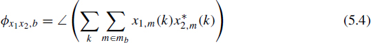
Using the ICPD as specified in Equation (5.4), (relative) delays between the input signals are represented as a constant phase difference in each parameter band, hence resulting in a piecewise constant phase characteristic which is a somewhat limited model for the delay. On the other hand, constant phase differences across the input signals are described accurately, which is in turn not possible if an ICTD parameter (i.e., a parameterized slope of phase with frequency) had been used. The (absence of) perceptual consequences by replacing time differences with parameter-band phase differences is discussed in Chapter 7.
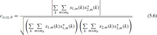
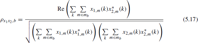
The third parameter is the inter-channel coherence (cx1x2,b), which is, in this context, defined as the normalized cross-correlation coefficient after phase alignment according to the ICPD. The coherence cx1x2,b is derived from the cross-spectrum by first applying the ICPD parameter to align the two input signals, followed by computing the cross-correlation of the phase-aligned signals:
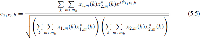
which can also be written as
5.4.3 Down-mix
A suitable mono signal s1,m(k) is obtained by a linear combination of the input signals x1,m(k) and x2,m(k):
![]()
where w1,b and w2,b are weights that determine the relative amount of x1,m(k) and x2,m(k) in the mono output signal. For example, if w1,b = w2,b = 0.5, the output will consist of the average of the two input signals. A down-mix that is created using fixed weights however bears the risk that the power of the down-mix signal strongly depends on the cross-correlation of the two input signals. To circumvent signal loss and signal coloration due to time- and frequency-dependent cross-correlations, the weights w1,b and w2,b are (1) complex-valued, to prevent phase cancellation, and (2) varying in magnitude across frequency or parameter bands (b), to ensure overall power preservation.
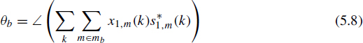
When the mono signal is generated, the last parameter that has to be extracted is computed. The ICPD parameter as described above specifies the relative phase difference between the stereo input signal (at the encoder) and the stereo output signals (at the decoder). Hence the ICPD does not indicate how the decoder should distribute these phase differences across the output channels. In other words, an ICPD parameter alone does not indicate whether a first signal is lagging the second signal, or vice versa. Thus, it is generally impossible to reconstruct the absolute phase for the stereo signal pair using only the relative phase difference. Absolute phase reconstruction is required to prevent signal cancellation in the applied overlap-add procedure in both the encoder as well as the decoder (see below). To signal the actual distribution of phase modifications, an overall channel phase difference (OCPD) is computed and transmitted. To be more specific, the decoder applies a phase modification equal to the OCPD to compute the first output signal, and applies a phase modification of the OCPD minus the ICPD to obtain the second output signal. Given this specification, the OCPD θb for parameter band b is computed as the average phase difference between x1,m(k) and s1,m(k), following
Subsequently, the mono signal s1,m(k) is transformed to the time domain to result in the mono output signal.
5.4.4 Parameter quantization and coding
The ICLD, ICPD, OCPD and ICC parameters are quantized according to perceptual criteria. The quantization process aims at introducing quantization errors which are just inaudible. For the ICLD, this constraint requires a nonlinear quantizer, or nonlinearly spaced ICLD values given the fact that the sensitivity for changes in ICLD depends on the reference ICLD. The vector ΔL contains the possible discrete ICLD values ΔL that are available for the quantizer. Each element in ΔL represents a single quantization level for the ICLD parameter and is indicated by ΔLq(i) (i= (0,. . ., 30)):
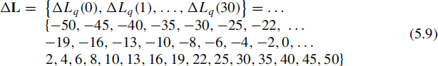
The ICLD index for sub-band b, iΔLx1x2,b, is then equal to

For the ICPD parameter, the vector ϕ represents the available quantized ICPD values ϕq:
![]()
This repertoire is in line with the finding that the human sensitivity to changes in timing differences at low frequencies can be described by a constant phase difference sensitivity. The ICPD index for sub-band b, iϕx1x2,b, is given by:

where mod(·) means the modulo operator, ![]() the floor function and Λϕ the cardinality of the set of possible quantized ICPD values (i.e., the number of elements in ϕ). The OCPD (θb) is quantized using the same quantizer, resulting in iθb according to
the floor function and Λϕ the cardinality of the set of possible quantized ICPD values (i.e., the number of elements in ϕ). The OCPD (θb) is quantized using the same quantizer, resulting in iθb according to

Finally, the repertoire for ICC, represented in the vector c, is given by:
![]()
This repertoire is based on just-noticeable differences in correlation reported by [63]. The coherence index icx1x2,b for sub-band b is determined by

Thus, for each frame, B indices for the ICLD and ICC have to be transmitted. The ICPD and OCPD indices are not transmitted for sub-bands b > 17 for B = 34 (for B = 20 (or 10), only 11 (or 5) ICPD and OCPD parameters are transmitted). Hence the bandwidth for (interaural) phase reconstruction is limited to approximately 2400 Hz (assuming fs = 44100 Hz), given the fact that the human auditory system is insensitive to fine-structure phase differences at high frequencies. ICTDs present in the high-frequency envelopes are supposed to be represented by the time-varying nature of ICLD parameters (hence discarding ICTDs presented in envelopes that fluctuate faster than the parameter update rate).
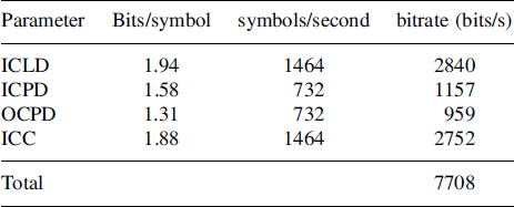
All parameters are transmitted differentially across time. The time-differential parameter indices are efficiently represented using entropy coding. The entropy per symbol, using modulo-differential coding and the resulting contribution to the overall bitrate (for B = 34 and a parameter update rate of 23 ms) are given in Table 5.2. These numbers were obtained by analysis of 80 different stereo audio recordings representing a large variety of material.
The total estimated parameter bitrate for the configuration as described above, excluding bitstream overhead, and averaged across a large amount of representative stereo material amounts to 7.7 kbit/s. If further parameter bitrate reduction is required, the following changes can be made.
- Reduction of the number of parameter bands (e.g., using 10 or 20 instead of 34). The parameter bitrate increases approximately linearly with the number of bands. This results in a bitrate of approximately 4.5 kbit/s for the 20 band case, assuming an update rate of 23 ms and including transmission of ICPD and OCPD parameters. Informal listening experiments showed that lowering the number of frequency bands below 10 results in severe degradation of the perceived spatial quality.
Table 5.2 Entropy per parameter symbol, number of symbols per second and bitrate for spatial parameters using 34 parameter bands and an update rate of 23 ms.
- No transmission of ICPD and OCPD parameters. As described above, the coherence is a measure of the difference between the input signals which cannot be accounted for by (sub-band) phase and level differences. A lower bitrate is obtained if the applied signal model does not incorporate phase differences. In that case, the normalized crosscorrelation ρx1x2 is the relevant measure of differences between the input signals that cannot be accounted for by level differences. In other words, phase or time differences between the input signals are modeled as (additional) changes (decreases) in the coherence:

The estimated cross-correlation value is then derived from the cross spectrum following:
The associated average bit-rate reduction amounts to approximately 27% compared with parameter sets which do include the ICPD and OCPD values. Furthermore, the possible range of the ICC parameter now also includes negative values, which requires special attention at the decoder side (see also Section 5.5.3).
- Increasing the quantization errors of the parameters. The bitrate reduction is only marginal, given the fact that the distribution of time-differential parameters is very peaky.
- Decreasing the parameter update rate. The bitrate scales approximately linearly with the update rate.
In summary, the parameter bitrate can be scaled between approximately 8 kbit/s for maximum quality (using 34 parameter bands, an update rate of 23 ms and transmitting all relevant parameters) to about 1.5 kbit/s (using 20 parameter bands, an update rate of 46 ms, and no transmission of ICPD and OCPD parameters).