


Virtualization of IBM Spectrum Accelerate storage systems
This chapter describes how to virtualize external storage systems from the IBM Spectrum Accelerate™ family as Internet Small Computer System Interface (iSCSI) targets, including IBM XIV® systems, IBM FlashSystem® A9000 systems, and IBM Spectrum Accelerate software-defined storage (SDS) solutions.
The chapter contains the following sections:
For comprehensive descriptions of concepts, architecture, and implementation of these storage systems see the following IBM Redbooks publications:
•IBM XIV Storage System Architecture and Implementation, SG24-7659
•IBM FlashSystem A9000 and IBM FlashSystem A9000R Architecture and Implementation, SG24-8345
•IBM Spectrum Accelerate Deployment, Usage, and Maintenance, SG24-8267
13.1 Planning considerations
IBM Spectrum Accelerate storage systems support horizontal scale-out capability, which means a single system can have 3 - 15 nodes (or modules). The connectivity paradigm for virtualization by a SAN Volume Controller or IBM Storwize system is determined by the characteristics of the XIV, IBM FlashSystem A9000, and IBM Spectrum Accelerate iSCSI targets:
•Each target port has its own IP address.
•The system has a single system-wide IQN that handles all connections.
•All iSCSI LUNs are visible through every iSCSI session.
For redundancy, you must connect at least two target nodes to two or more SAN Volume Controller or IBM Storwize initiator ports through different Ethernet switches. More connections can be configured between a source system and a target, depending on the availability of source ports with storage connectivity enabled. Figure 13-1 shows the connection schema.

Figure 13-1 Connecting a virtualized XIV, IBM FlashSystem A9000, IBM FlashSystem A9000R, or IBM Spectrum Accelerate iSCSI storage system
In this example, the IBM Storwize system consists of two control enclosures (I/O groups) with two initiator nodes per enclosure. Each node has four Ethernet ports, labeled as IPA (first port of the first node) to IPP (fourth port of the fourth node). Two ports per node are configured as initiator ports through two switches to target ports of the IBM Spectrum Accelerate system. The other two Ethernet ports on each node are not configured.
The first ports (orange) on each initiator and target node are connected through Ethernet switch 1. The second ports (blue) on each initiator and target node are connected through Ethernet switch 2. Because of the system-wide IQN, each Storwize initiator node can access all IBM Spectrum Accelerate LUNs.
When you define initiator port connections, the configuration applies to all the ports on the system. That means in this example, the following items are true:
•Port IP1 on IBM Spectrum Accelerate node 1 is the target port for IBM Storwize source ports IPA, IPE, IPI, and IPM.
•Port IP5 on IBM Spectrum Accelerate node 2 is the target port for IBM Storwize source ports IPB, IPF, IPJ, and IPN.
Figure 13-1 on page 240 shows the minimum configuration with redundancy. In this configuration, extra Ethernet ports remain unconfigured but can be connected to increase the throughput. You can connect to as many XIV target ports across nodes equal to SAN Volume Controller or IBM Storwize initiator ports.
|
Important: The current implementation of iSCSI virtualization supports only one XIV target port per SAN Volume Controller or IBM Storwize initiator port. You must connect different target ports to different initiator ports.
|
In Figure 13-1 on page 240, the initiator ports IPC, IPD, IPG, IPH, IPK, IPL, IPO, and IPP remain unconfigured. On the target nodes, ports IP2, IP3, IP4, IP6, IP7, and IP8 are also unconfigured. Initiator ports IPC, IPG, IPK, and IPO can be connected through Ethernet switch 1 to any unused target port across the target nodes. When these connections are configured, another path between the source and target nodes is created. Similarly, the initiator ports IPD, IPH, IPL, and IPP can be connected through Ethernet switch 2 to any unused target port across the target nodes.
13.1.1 Limits and considerations for IBM XIV, IBM FlashSystem A9000, and IBM Spectrum Accelerate
For XIV, IBM FlashSystem A9000, and IBM Spectrum Accelerate systems, the number of iSCSI ports per node or module varies by model. For more information, see the following publications:
•IBM XIV Storage System Architecture and Implementation, SG24-7659
•IBM FlashSystem A9000 and IBM FlashSystem A9000R Architecture and Implementation, SG24-8345
•IBM Spectrum Accelerate Deployment, Usage, and Maintenance, SG24-8267
Here are the minimum code versions for iSCSI virtualization:
•XIV Gen3 firmware 11.2.0.c
•IBM FlashSystem A9000 firmware 12.0.0
•IBM Spectrum Accelerate software 11.5.x
XIV, IBM FlashSystem A9000, and IBM Spectrum Accelerate systems do not support IP link aggregation. Ethernet ports cannot be bonded.
The SAN Volume Controller and IBM Storwize Family iSCSI Storage Attachment Support Matrix provides up-to-date information.
13.1.2 Performance considerations
The default maximum transmission unit (MTU) of these storage systems is 4500 bytes. To match the SAN Volume Controller or IBM Storwize initiators, you should set the MTU to 9000 bytes. That is the upper limit for the MTU on XIV, IBM FlashSystem A9000, and IBM Spectrum Accelerate systems. As a prerequisite, you must configure the whole network to this MTU value if it is supported by your switches and routers. If you want an MTU other than the default, then it must be configured for each target port of the XIV, IBM FlashSystem A9000, or IBM Spectrum Accelerate system.
|
Tip: If the MTU that is being used by the XIV system is higher than the network can transmit, the frames are discarded. The frames are discarded because the do-not-fragment bit is normally set to on. Use the ping -l command to test the specification of the packet payload size from a Windows workstation in the same subnet. A ping command normally contains 28 bytes of IP and ICMP headers plus payload. Add the -f parameter to prevent packet fragmentation.
For example, the ping -f -l 8972 10.1.1.1 command sends a 9000-byte frame to the 10.1.1.1 IP address (8972 bytes of payload and 28 bytes of headers). If this command succeeds, then you can configure an MTU of 9000 in the XIV GUI or XCLI.
|
13.1.3 Migration considerations
If iSCSI hosts are already attached to the XIV system, then their target ports are often configured with a smaller MTU size. Typical values are 1500 or 4500 bytes. Setting the MTU size to 9000 for virtualization and attaching these hosts to the SAN Volume Controller or IBM Storwize system can cause performance and stability issues during the migration because the XIV ports send large frames to the SAN Volume Controller or IBM Storwize nodes and to the hosts.
Therefore, you must consider this issue in your migration plan. Here are two options:
•You use different XIV target ports for SAN Volume Controller or IBM Storwize nodes and for the hosts. The target ports for the SAN Volume Controller or IBM Storwize initiators are reconfigured with an MTU of 9000 bytes (or the best value that the switches and routers support). The target ports for the hosts remain unchanged until hosts do not need these ports anymore.
When all migration tasks are complete, the target ports for the hosts can be reconfigured for usage as extra virtualization ports.
•Alternatively, you can configure the SAN Volume Controller or IBM Storwize nodes to use the smaller MTU size for migration. Therefore, these initiator nodes and the hosts can share target ports.
When all migration tasks are complete, and SAN Volume Controller or IBM Storwize nodes are the only initiators for the XIV ports, you change the MTU size to the optimal value.
13.2 Target configuration
To configure your XIV, IBM FlashSystem A9000, and IBM Spectrum Accelerate system, you must install the Hyper-Scale Manager graphical user interface (GUI) and the XIV command-line interface (XCLI) on your workstation. You log in to the GUI or XCLI and add the iSCSI target system to the inventory. (For more information about how to configure the GUI and XCLI, see the IBM Redbooks publications for your system.)
|
Note: The examples show an XIV Storage System (machine type 2810), but apply also to IBM FlashSystem A9000 and IBM Spectrum Accelerate systems.
|
Every XIV system has a unique IQN. The format of the IQN is simple, and includes a fixed text string followed by the last digits of the system’s serial number.
|
Important: Do not attempt to change the IQN. If you need to change the IQN, you must engage IBM Support.
|
To display the IQN of the XIV Storage System, complete the following steps:
1. From the XIV GUI, click Systems → System Settings → System.
If you are displaying multiple XIV systems from the All Systems view, you can right-click an XIV system, and select Properties → Parameters to get the same information.
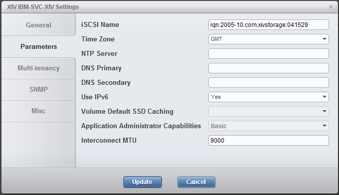
Figure 13-2 XIV system settings with iSCSI IQN
To show the same information in the XCLI, run the XCLI config_get command, as shown in Example 13-1.
Example 13-1 XIV system settings in XCLI
XIV IBM-SVC-XIV>>config_get
Name Value
dns_primary
dns_secondary
system_name XIV IBM-SVC-XIV
snmp_location Unknown
snmp_contact Unknown
snmp_community XIV
snmp_trap_community XIV
snmp_type V2C
snmpv3_user
snmpv3_encryption_type AES
snmpv3_encryption_passphrase ****
snmpv3_authentication_type SHA
snmpv3_authentication_passphrase ****
system_id 41529
machine_type 2810
machine_model 999
machine_serial_number 9041529
machine_unique_id a9d61f84264c42a8895b3ccaae95fb2e
email_sender_address
email_reply_to_address
email_subject_format {severity}: {description}
iscsi_name iqn.2005-10.com.xivstorage:041529
ntp_server
support_center_port_type Management
isns_server
ipv6_state enabled
ipsec_state disabled
ipsec_track_tunnels no
impending_power_loss_detection_method UPS
After installing the XIV management tools and collecting the necessary information, you configure the XIV system in three steps:
1. Configure the iSCSI target ports (13.2.1, “Port configuration” on page 245).
2. Define the SAN Volume Controller or IBM Storwize initiator nodes as hosts (13.2.2, “Host mappings and authentication” on page 247).
3. Map XIV LUNs to these nodes (13.2.3, “Mapping XIV LUNs to the SAN Volume Controller or IBM Storwize system” on page 253).
13.2.1 Port configuration
To set up the iSCSI ports, complete these steps:
1. From the XIV GUI, select View → Host and Clusters → iSCSI Connectivity, and then click Define IP Interface - iSCSI.
2. In the window that opens (Figure 13-3), enter the parameters for one iSCSI target port:
– If you are managing multiple XIV systems from the GUI, select the iSCSI target system from the Systems drop-down menu.
– In the Name field, enter a text string to identify this port in other GUI panes and XCLI output. In the example, the string describes the port as Module 1, iSCSI port 1.
– Specify the IP address, the netmask, and the default gateway in the next fields.
– Set the MTU to 9000, if it is supported by your network.
– From the drop-down menu Node and the Port Number switch, select the module and its port to which these settings apply. (The Port Number switch varies, depending on the ports that are available in this module.)
3. Click Define to complete the IP interface and iSCSI setup.

Figure 13-3 Defining an IP interface for iSCSI
To configure iSCSI ports by using the XCLI, enter the ipinterface_create command, as shown in Example 13-2.
Example 13-2 Defining an IP interface for iSCSI by using XCLI
XIV IBM-SVC-XIV>>ipinterface_create ipinterface="mod1-iscsi-p1" address=192.168.100.121 netmask=255.255.0.0 module=1:Module:1 ports="1" gateway=192.168.100.1 mtu=9000
As explained in 13.1, “Planning considerations” on page 240, you must configure at least two iSCSI target ports in different XIV modules. Therefore, the minimum configuration of iSCSI ports in the XIV GUI looks like Figure 13-4.
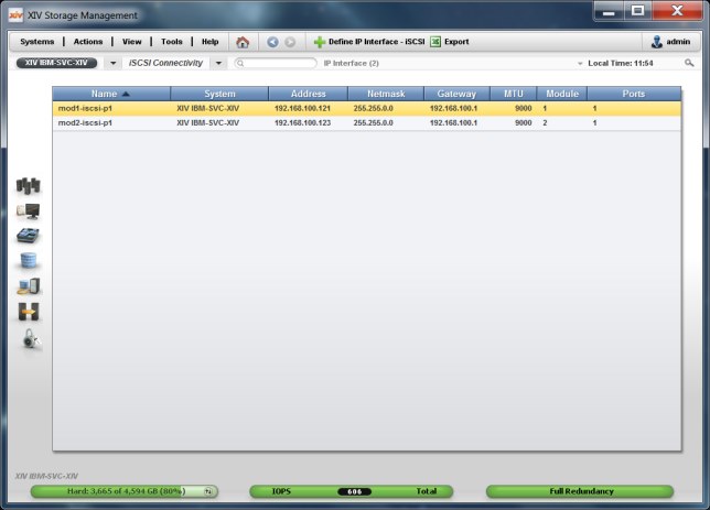
Figure 13-4 Minimum iSCSI port configuration in the XIV GUI
To show the same information in the XCLI, run the XCLI ipinterface_list command, as shown in Example 13-3.
Example 13-3 Minimum iSCSI port configuration in XCLI
XIV IBM-SVC-XIV>>ipinterface_list
Name Type IP Address Network Mask Default Gateway IPv6 Address IPv6 Gateway MTU Module Ports IP access group name
management Management 9.113.57.64 255.255.254.0 9.113.56.1 1500 1:Module:1
interconnect Interconnect 192.168.64.161 255.255.255.0 9000 1:Module:1
management Management 9.113.57.65 255.255.254.0 9.113.56.1 1500 1:Module:2
interconnect Interconnect 192.168.64.162 255.255.255.0 9000 1:Module:2
management Management 9.113.57.78 255.255.254.0 9.113.56.1 1500 1:Module:3
interconnect Interconnect 192.168.64.163 255.255.255.0 9000 1:Module:3
mod1-iscsi-p1 iSCSI 192.168.100.121 255.255.0.0 192.168.100.1 9000 1:Module:1 1
mod2-iscsi-p1 iSCSI 192.168.100.123 255.255.0.0 192.168.100.1 9000 1:Module:2 1
The ipinterface_list command displays configured network ports only. The output lines that are highlighted in blue correspond to the same two iSCSI ports that are shown in Figure 13-4 on page 246. The other output lines display XIV management and interconnect ports. The rows might be in a different order each time you run this command. To see a complete list of IP interfaces, use the ipinterface_list_ports command.
13.2.2 Host mappings and authentication
The XIV, IBM FlashSystem A9000, and IBM Spectrum Accelerate systems support unidirectional iSCSI Challenge Handshake Authentication Protocol (CHAP).
|
Note: The CHAP configuration is defined on a per-initiator basis. There are no global configurations for CHAP that affect all the initiators that are connected to the system.
|
For the iSCSI initiator to log in with CHAP, both the iscsi_chap_name and the iscsi_chap_secret parameters must be set. After both of these parameters are set, the initiator can run an iSCSI login to the IBM XIV Storage System only if the login information is correct.
CHAP name and secret parameter guidelines
The following guidelines apply to the CHAP name and secret parameters:
•Both the iscsi_chap_name and iscsi_chap_secret parameters must either be specified or not specified. You cannot specify just one of them.
•The iscsi_chap_name and iscsi_chap_secret parameters must be unique. If they are not unique, an error message is displayed. However, the command does not fail.
•The secret must be 96 - 128 bits. You can use one of the following methods to enter the secret:
– Base64 requires that 0b is used as a prefix for the entry. Each subsequent character that is entered is treated as a 6-bit equivalent length.
– Hex requires that 0x is used as a prefix for the entry. Each subsequent character that is entered is treated as a 4-bit equivalent length.
– String requires that a prefix is not used (it cannot be prefixed with 0b or 0x). Each character that is entered is treated as an 8-bit equivalent length.
•If the iscsi_chap_secret parameter does not conform to the required secret length (96 - 128 bits), the command fails.
•If you change the iscsi_chap_name or iscsi_chap_secret parameters, a warning message is displayed. The message says that the changes will be applied the next time that the host is connected.
CHAP can be configured either through the XIV GUI or through XCLI when you add the iSCSI initiators as XIV hosts. The SAN Volume Controller or IBM Storwize nodes that act as iSCSI initiators must be configured as iSCSI hosts in the XIV, IBM FlashSystem A9000, or IBM Spectrum Accelerate system.
|
Tip: Because all initiator nodes share the XIV LUNs to be virtualized, you configure these nodes as a cluster of hosts.
|
The section “Configuring SAN Volume Controller or IBM Storwize nodes as XIV hosts with the GUI” describes how to configure the initiator nodes as a host cluster with the XIV GUI. The section “Configuring SAN Volume Controller or IBM Storwize nodes as XIV hosts with the XCLI” on page 252 explains the same procedure with the XCLI. When the initiators are configured as hosts, you can map XIV LUNs to them, as shown in 13.2.3, “Mapping XIV LUNs to the SAN Volume Controller or IBM Storwize system” on page 253.
Configuring SAN Volume Controller or IBM Storwize nodes as XIV hosts with the GUI
To configure the SAN Volume Controller or Storwize nodes as XIV hosts with the GUI, complete these steps:
1. In the XIV Storage System main GUI window, hover your cursor over the Hosts and Clusters icon and select Hosts and Clusters. Alternatively, you can select View → Hosts and Clusters → Hosts and Clusters from the top menu bar.
2. The Hosts window opens, and shows a list of hosts (if any) that are already defined. To add a cluster, click Add Cluster.
3. The Add Cluster dialog box opens, as shown in Figure 13-5. Enter a name for the cluster. For the Type, the default option is correct.
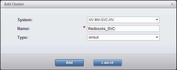
Figure 13-5 Add Cluster dialog box
4. To add a node to the cluster, select the cluster in the Hosts and Clusters pane, right-click, and select Add Host (Figure 13-6).
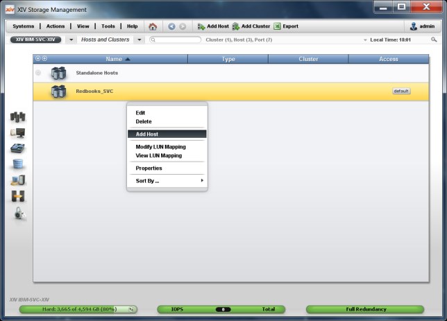
Figure 13-6 Adding a host to the cluster
5. The Add Host dialog box opens, as shown in Figure 13-7. Enter a name that identifies your SAN Volume Controller or IBM Storwize node. For the Type, the default option is correct. Enter the CHAP name and the CHAP secret.
|
Important: You must use the same CHAP name and CHAP secret for each initiator node because the target discovery runs on all connected SAN Volume Controller or IBM Storwize nodes for the single system-wide target IQN.
|

Figure 13-7 Host parameters
6. After adding all SAN Volume Controller or IBM Storwize nodes as hosts to the cluster, the Hosts and Clusters pane looks similar to Figure 13-8.
Host access to XIV LUNs is granted depending on the host adapter ID. For an iSCSI connection, the host adapter ID is the initiator IQN. To add an IQN to a host definition, right-click the host and select Add Port from the menu.

Figure 13-8 Adding a port to a node of the SAN Volume Controller or IBM Storwize cluster
7. The Add Port window opens, as shown in Figure 13-9. Select iSCSI as the Port Type and enter the IQN of the node as the iSCSI Name.
Because all Ethernet ports of a SAN Volume Controller or IBM Storwize node use the same IQN, a single iSCSI port definition per host is sufficient, independent of the number of Ethernet ports.
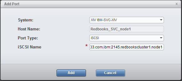
Figure 13-9 iSCSI initiator port parameters
8. Repeat steps 4 on page 249 to 7 for all initiator nodes in your SAN Volume Controller or IBM Storwize cluster.
Now, map your XIV LUNs to your SAN Volume Controller or IBM Storwize system (see 13.2.3, “Mapping XIV LUNs to the SAN Volume Controller or IBM Storwize system” on page 253). The XIV Host Connectivity GUI pane does not show any connections to the newly configured ISCSI hosts. You see the connections after the iSCSI discovery during the initiator configuration (see 13.3, “Initiator configuration” on page 254).
Configuring SAN Volume Controller or IBM Storwize nodes as XIV hosts with the XCLI
To configure the SAN Volume Controller or IBM Storwize nodes as XIV hosts with the XCLI, complete these steps:
1. Define a cluster by using the cluster_create command:
cluster_create cluster=[SVCClusterName]
2. Define a host as a member of this cluster by using the host_define command:
host_define host=[SVCNodeName] cluster=[SVCClusterName] iscsi_chap_name=[SVCChapName] iscsi_chap_secret=[SVCChapSecret]
|
Important: You must use the same CHAP name and CHAP secret for each initiator node because the target discovery runs on all connected SAN Volume Controller or IBM Storwize nodes for the single system-wide target IQN.
|
3. Add an iSCSI port by using the host_add_port command:
host_add_port host=[SVCNodeName] iscsi_name=[SVCNodeIQN]
Because all Ethernet ports of a SAN Volume Controller or IBM Storwize node use the same IQN, a single port definition per host name is sufficient, independent of the number of Ethernet ports.
4. Repeat steps 2 and 3 for all initiator nodes of your SAN Volume Controller or IBM Storwize cluster.
Now, map XIV LUNs to your SAN Volume Controller or IBM Storwize system (see 13.2.3, “Mapping XIV LUNs to the SAN Volume Controller or IBM Storwize system” on page 253). The output of the XCLI host_list command does not show any connections to the newly configured ISCSI hosts. You see the connections after the iSCSI discovery during the initiator configuration (see 13.3, “Initiator configuration” on page 254).
13.2.3 Mapping XIV LUNs to the SAN Volume Controller or IBM Storwize system
The final configuration step is to map XIV LUNs (that becomes MDisks) to the initiator nodes. Using the GUI, complete the following steps:
1. In the Hosts and Clusters configuration window, right-click the cluster of your initiator nodes to which the LUN is to be mapped and select Modify LUN Mappings (Figure 13-10).

Figure 13-10 Modifying the LUN mapping in the XIV GUI
2. The Volume to LUN Mapping window opens, as shown in Figure 13-11. Select the volume that will become an MDisk from the left pane. The GUI suggests a LUN ID to which to map the volume; there is no need to change it. Click Map and the volume is assigned immediately.
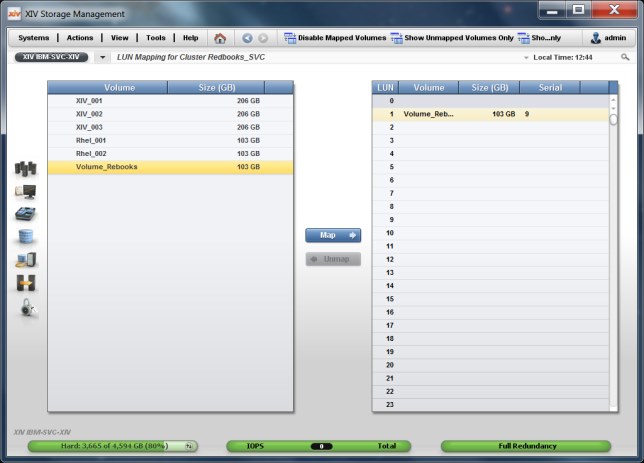
Figure 13-11 Selecting a LUN for mapping in the XIV GUI
Alternatively, you can use the map_vol command to map a LUN to the cluster of initiator nodes, as shown in Example 13-4. The LUN ID is a mandatory parameter.
Example 13-4 Mapping an XIV LUN to the cluster iSCSI initiator nodes
XIV IBM-SVC-XIV>>map_vol cluster=Redbooks_SVC vol=Volume_Redbooks lun=1
13.3 Initiator configuration
After mapping the XIV LUNs (which become MDisks) to the SAN Volume Controller or Storwize cluster, you configure these cluster nodes as initiators. The following sections describe how to accomplish this task:
•Section 13.3.1, “Overview” on page 255 gives an overview of the whole procedure.
•Section 13.3.2, “Workflow that uses the CLI” on page 255 shows the detailed configuration steps by using the CLI.
•Section 13.3.3, “Workflow with GUI” on page 257 shows the configuration by using the GUI.
•Section 13.3.4, “Configuration validation” on page 261 explains how to validate the configuration before you create SAN Volume Controller or IBM Storwize volumes.
13.3.1 Overview
As a prerequisite, the SAN Volume Controller or IBM Storwize initiator ports must be configured with IPv4 or IPv6 addresses. For more information, see Chapter 11, “iSCSI virtualization overview” on page 213.
The configuration procedure for the SAN Volume Controller or IBM Storwize initiators consists of two phases:
•Discovery of the targets
•Session establishment to these targets
You must repeat these two phases for each initiator port. Section 13.3.2, “Workflow that uses the CLI” on page 255 explains these steps by using the CLI. Section 13.3.2, “Workflow that uses the CLI” on page 255 shows the steps by using the GUI.
13.3.2 Workflow that uses the CLI
To configure the XIV, IBM FlashSystem A9000, or IBM Spectrum Accelerate storage system as an external iSCSI controller, complete the following steps:
1. to discover manually the XIV iSCSI target with the provided IP and CHAP secret, run the following command:
detectiscsistorageportcandidate -targetip [XIVIP1] -srcportid [SVCSourcePortID] -username [SVCChapName] -chapsecret [SVCChapSecret]
The [SVCChapName] and [SVCChapSecret] values must match the [SVCChapName] and [SVCChapSecret] values that are specified for authentication for the XIV system’s host mappings (see 13.2.2, “Host mappings and authentication” on page 247). Otherwise, the SAN Volume Controller or IBM Storwize system cannot detect the XIV target ports.
2. List the status of the most recently discovered target by running the following command:
lsiscsistorageportcandidate
3. After the discovery was successful, you can establish sessions from the initiator port to the most recently discovered target by running the following command:
addiscsistorageport -username [SVCChapName] -chapsecret [SVCChapSecret] [ID]
In this command, [ID] is the row ID of the lsiscsistorageportcandidate command in step 2. Again, the [SVCChapName] and [SVCChapSecret] values are the same as specified for authentication for the XIV system’s host mappings.
4. Verify that new sessions are established by running the following command:
lsiscsistorageport
The command lists the status of the initiator and target for each session in separate rows.
Additionally, you can verify the detailed status of initiator node connectivity through the ports to the target by running the following command:
lsiscistorageport [ID]
5. Repeat steps 1 on page 255 to 4 on page 255 for each initiator port. Choose a different target IP each time, as described in 13.1, “Planning considerations” on page 240.
Example 13-5 Initiator port configuration
# Step 1 on page 255: Discover the XIV iSCSI target 192.168.100.121 from initiator port 3.
IBM_2145:Redbooks_cluster1:superuser>detectiscsistorageportcandidate -targetip 192.168.100.121 -srcportid 3 -username XIVchap -chapsecret Redbooks12345
#
# Step 2 on page 255: List the status of the most recently discovered target.
# The single output row (with ID 0) shows the target from source port 3 in IO group 1.
IBM_2145:Redbooks_cluster1:superuser>lsiscsistorageportcandidate
id src_port_id target_ipv4 target_ipv6 target_iscsiname iogroup_list configured status site_id site_name
0 3 192.168.100.121 iqn.2005-10.com.xivstorage:041529 1:-:-:- no full
#
# Step 3 on page 255: Establish sessions from the initiator port to the most recently discovered target.
# Use the row ID 0 from the previous output as parameter in this command.
IBM_2145:Redbooks_cluster1:superuser>addiscsistorageport -username XIVchap -chapsecret Redbooks12345 0
#
# Step 4 on page 255: Verify that new sessions had been established.
# (Extra output rows for other iSCSI controllers omitted.)
IBM_2145:Redbooks_cluster1:superuser>lsiscsistorageport
id src_port_id target_ipv4 target_ipv6 target_iscsiname controller_id
iogroup_list status site_id site_name
4 3 192.168.100.121 iqn.2005-10.com.xivstorage:041529 3
1:-:-:- full
Now, you can configure the XIV LUNs that are mapped to the cluster of initiator nodes (see 13.2.3, “Mapping XIV LUNs to the SAN Volume Controller or IBM Storwize system” on page 253) as managed disks in the SAN Volume Controller or IBM Storwize system. The steps are the same as for external LUNs that are attached through Fibre Channel (FC):
1. Verify the controller by using the lscontroller command.
2. Discover the managed disks by using the detectmdisk command.
3. Verify the managed disks with the lsmdisk command.
4. Create a pool by running the mkmdiskgrp command if necessary and add the managed disks to the pool by running the addmdisk command.
Example 13-6 shows that the XIV LUNs that are mapped in the examples of 13.2.3, “Mapping XIV LUNs to the SAN Volume Controller or IBM Storwize system” on page 253. (Extra output rows for other external controllers are omitted.)
Example 13-6 Configuration of the XIV LUNs as managed disks
# Step 1: Verify the controller.
# The XIV system is shown as controller4.
IBM_2145:Redbooks_cluster1:superuser>lscontroller
id controller_name ctrl_s/n vendor_id product_id_low product_id_high site_id site_name
0 controller4 A2390000 IBM 2810XIV- LUN-0
#
# Step 2: Discover the new LUNs.
# The command completes asynchronously and can take some minutes to complete.
IBM_2145:Redbooks_cluster1:superuser>detectmdisk
#
# Step 3 on page 256: Verify the LUNs.
# The MDisk with ID 7 is presented by controller4 in status unmanaged.
IBM_2145:Redbooks_cluster1:superuser>lsmdisk
id name status mode mdisk_grp_id mdisk_grp_name capacity ctrl_LUN_# controller_name UID tier encrypt site_id site_name distributed dedupe
7 mdisk7 online unmanaged 96.2GB 0000000000000001 controller4 00173800a2390009000000000000000000000000000000000000000000000000 tier_enterprise no no no
#
# Step 4 on page 256: Create a pool and add the MDisk with ID 7 to this pool.
IBM_2145:Redbooks_cluster1:superuser>mkmdiskgrp -name XIVpool -mdisk 7 -ext 1024
MDisk Group, id [0], successfully created
13.3.3 Workflow with GUI
To configure the XIV, IBM FlashSystem A9000, or IBM Spectrum Accelerate storage system as an external iSCSI controller by using the SAN Volume Controller or Storwize GUI, complete the following steps:

Figure 13-12 External Storage window to add external iSCSI storage
2. The dialog box to select the type of the iSCSI controller opens (Figure 13-13). Select IBM Spectrum Accelerate for XIV, IBM FlashSystem A9000, and IBM Spectrum Accelerate systems.

Figure 13-13 Selecting the type of the iSCSI storage controller
3. Click Next. The window for the iSCSI controller parameters opens (Figure 13-14). Enter the CHAP name (as User name), the CHAP secret, and at least two initiator port names with their XIV target port addresses.
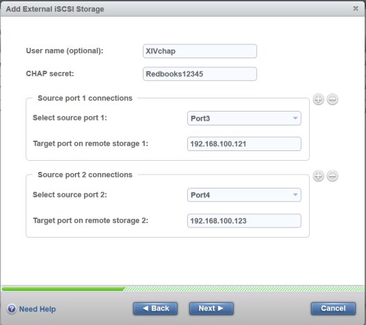
Figure 13-14 iSCSI controller parameters

Figure 13-15 iSCSI controller summary
5. The External Storage window shows the new controller with its LUNs as MDisks (Figure 13-16).
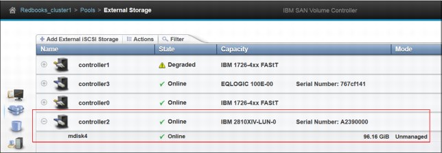
Figure 13-16 New external iSCSI controller with LUN
Now, you can configure the XIV LUNs that are mapped to the cluster of initiator nodes (see 13.2.3, “Mapping XIV LUNs to the SAN Volume Controller or IBM Storwize system” on page 253) as managed disks in the SAN Volume Controller or IBM Storwize system. The steps are the same as for external LUNs that are attached through FC, that is, click Pools → MDisks by Pools, create a pool if necessary, and add the managed disks to the pool (Figure 13-17).

Figure 13-17 MDisks from the XIV that is configured in the new pool
13.3.4 Configuration validation
To validate the configuration from the initiator side, you can use the lsiscsistorageport command. Without parameters, the command lists all the established iSCSI sessions. Then, you see the row IDs of this output in lsiscsiport [ID] commands to display the details of the XIV sessions. Example 13-7 shows an output for the iSCSI session that is configured in 13.3.2, “Workflow that uses the CLI” on page 255.
Example 13-7 Detailed output of lsiscsiport
IBM_2145:Redbooks_cluster1:superuser>lsiscsistorageport 1
id 1
src_port_id 3
target_ipv4 192.168.100.121
target_ipv6
target_iscsiname iqn.2005-10.com.xivstorage:041529
controller_id 3
iogroup_list 1:-:-:-
status full
site_id
site_name
node_id 1
node_name node1
src_ipv4 192.168.104.199
src_ipv6
src_iscsiname iqn.1986-03.com.ibm:2145.redbookscluster1.node1
connected yes
node_id 2
node_name node2
src_ipv4 192.168.104.197
src_ipv6
src_iscsiname iqn.1986-03.com.ibm:2145.redbookscluster1.node2
connected yes
The iogroup_list field shows a colon-separated list of discovery result codes per I/O group:
•Value 0 indicates that the I/O group is available in the system, but discovery is either not triggered through the I/O group or discovery through the I/O group failed.
•Value 1 indicates that the I/O group is present and discovery is successful through the I/O group.
•Value - (dash) indicates that the I/O group is not valid or is not present in the system.
In this example, the first I/O group discovered successfully the iSCSI target (value 1 in field iogroup_list and value full in field status), and the fields connected show yes for both nodes of the I/O group.
For configuration validation from the target side, you can use XIV GUI window and select Hosts and Clusters → Host Connectivity (Figure 13-18).

Figure 13-18 XIV host connectivity from two initiator nodes to two target nodes (modules)
The green check marks show that two iSCSI initiators (from the host cluster Redbooks_SVC) successfully established sessions to port 1 in two different target nodes (modules 1:1 and 1:2). You can detect failed connections easily as missing check marks.
Using the XCLI, you can get the same output from the host_connectivity_list command, as shown in Example 13-8.
Example 13-8 XCLI output of host_connectivity_list with sessions from two initiator nodes to two target nodes
XIV IBM-SVC-XIV>>host_connectivity_list
Host Host Port Module Local FC port Local iSCSI port Type
Redbooks_SVC_node2 iqn.1986-03.com.ibm:2145.redbookscluster1.node2 1:Module:1 mod1-iscsi-p1 iSCSI
Redbooks_SVC_node1 iqn.1986-03.com.ibm:2145.redbookscluster1.node1 1:Module:1 mod1-iscsi-p1 iSCSI
Redbooks_SVC_node2 iqn.1986-03.com.ibm:2145.redbookscluster1.node2 1:Module:2 mod2-iscsi-p1 iSCSI
Redbooks_SVC_node1 iqn.1986-03.com.ibm:2145.redbookscluster1.node1 1:Module:2 mod2-iscsi-p1 iSCSI
For further analysis of connectivity from the XIV side, Table 13-1 lists some useful built-in tools. See the full XCLI command descriptions in the IBM XIV Storage System documentation.
Table 13-1 XIV built-in tools
|
Tool
|
Description
|
|
host_connectivity_list
|
Lists FC and iSCSI connectivity to hosts.
|
|
ipinterface_list_ports
|
Lists all Ethernet ports, their configuration, and their status.
|
|
ipinterface_run_arp
|
Prints the ARP database of a specified IP address.
|
|
ipinterface_run_traceroute
|
Tests connectivity to a remote IP address.
|
..................Content has been hidden....................
You can't read the all page of ebook, please click here login for view all page.