


External virtualization of Dell Equallogic PS Series
This chapter describes the IBM SAN Volume Controller cluster with support for the Internet Small Computer System Interface (iSCSI)-based external storage, and guidelines to virtualize a Dell Equallogic PS Series storage controller over iSCSI. This chapter also describes the command-line interface (CLI) and graphical user interface (GUI) configuration guidelines for initiator and target controllers, along with migration considerations.
This chapter describes the following topics:
14.1 Planning considerations
One of the first prerequisites to consider is the interconnect for the IP network. Figure 14-1 shows a suggested configuration for the Dell Equallogic PS Series connections in this chapter.

Figure 14-1 Connecting a Dell Equallogic PS Series iSCSI storage
Figure 14-1 provides a detailed description of the fundamentals of how to configure Dell Equallogic PS Series controllers with SAN Volume Controller. The front-end system consists of two SAN Volume Controller I/O groups, with each I/O group possessing two nodes. Each node has a maximum of four initiator ports. The target side that is shown in the figure reflects a Dell Equallogic PS Series controller with a group IP configured, which possess the access to the iSCSI qualified name (IQN) of each node. Ethernet switches are used for the networking that is required for the communication between the initiator and the target.
The ports that are colored in orange and blue signify the logic behind the establishment of the iSCSI sessions between the initiator and the target. IPA (initiator port-node1) on the initiator is connected to the group IP and eventually to IQN-1 through Ethernet switch 1. Similarly, IPB (initiator port-node1) is connected to the group IP and eventually to IQN-2 through the Ethernet switch 2. The same logic is implemented while connecting the initiator ports IPE and IPF to the IQN-1and IQN-2 by using the respective switches.
Also, while establishing sessions, defining the source ports implies that connections to the target ports will be established by all of the initiator ports on the system. The target IQN, IQN-1, will have sessions with IPA and IPE, which are the initiator ports on the system. The same is true for the target IQN, IQN-2, because they maintain sessions with IPB and IPF.
The ports that stand idle, both on the initiator and the target, can be used for further connections by using the same logic, which helps to increase throughput and the level of session redundancy.
14.1.1 Dell Equallogic PS Series connection considerations
This section describes the considerations when you connect a Dell Equallogic PS Series controller to a SAN Volume Controller or IBM Storwize system. You should consider these points while planning for the Dell Equallogic PS Series external storage for migration or virtualization.
No redundant paths per node
Connecting to the target IQN by using two ports of the same initiator nodes is not allowed. This is a limitation in the current code-line, which results in reduced session redundancy per node. There is I/O group-wide redundancy present because each node has one connection to back-end storage.
Session limits
Although it is possible to establish sessions by using both cluster-wide and I/O group-wide connectivity, it is preferable to have I/O group-wide connectivity because Dell has a limitation on the number of sessions between the initiator and the target system. Currently, 128 sessions to one back-end controller are allowed. Therefore, the recommendation is to exhaust the number of sessions to gain maximum storage access, and not to access the same storage through multiple I/O groups.
LUN mapping limits
Every LUN in the Dell controller has a unique IQN, and the session must be established with each LUN separately, which consumes many sessions from the initiator to the Dell controller. With the current available code version, only 64 LUNs can be virtualized from an external Dell controller. Therefore, it is preferable to have fewer larger LUNs to reduce the iSCSI sessions for the Dell controller if you are planning to connect the Dell controller for virtualization.
14.1.2 Migration considerations
In the Dell Equallogic PS Series implementation design, every volume is associated with one IQN and you must establish the session to the back-end LUN, which creates multiple iSCSI sessions and might reach the limit if not managed properly. The initiator system has a limit of 64 LUNs per external Dell Equallogic PS Series controller to be virtualized behind SAN Volume Controller or an IBM Storwize system. If there are more than 64 LUNs that are mapped to the initiator system from Dell Equallogic PS Series, discovery output is truncated, and only the first 64 LUNs are listed in the lsiscsistorageportcandidate output.
At the time of data migration from the internal Dell Equallogic PS Series controller to a SAN Volume Controller or IBM Storwize system, if there are more than 64 LUNs on Dell, consider migrating the LUNs in chunks of 64:
1. Connect the first 64 LUNs to the initiator system and migrate them to the SAN Volume Controller or IBM Storwize system.
2. Remove the target sessions when the migration is complete.
3. Change the access policy on the target Dell controller for those LUNs.
4. Remove the LUN access to the initiator system.
5. Now, redo the discovery and login process to connect another chunk of 64 LUNs to initiator system and perform migration activity.
14.2 Target configuration
To configure your Dell Equallogic PS Series system as a target controller for a SAN Volume Controller or IBM Storwize cluster, you must perform the initial setup activities that are described in the Dell documentation center to start the Dell system. (For more information about how to configure the Dell controller, see the product documentation for your system.) This initial setup includes using the setup utility to configure an array, and creating a PS Series group with the array as the initial group member.
For hardware installation information, see the PS Series QuickStart guide in your Dell documentation. The following subsections provide information about setting up Group IP and iSCSI IPs, volume creation, and access policy settings on the Dell Equallogic PS Series storage array:
14.2.1 Port configuration
This section provides information about Group IP configuration and iSCSI port configuration for the Dell Equallogic PS Series controller.
Setting up the Group IP
The Group IP address is the network address for the Dell controller group. You should use the Group IP address as the iSCSI discovery address when you connect initiators to iSCSI targets in the group. You also must use the Group IP address to access the group for management purposes, unless you configure a dedicated management network.
|
Prerequisite: Before changing the Group IP address or the Group name for a system that is already configured, check your Dell documentation for information about the effects of these changes.
Also, for more information, see Group Network Configuration.
|
While assigning IP addresses to Dell Equallogic PS Series Arrays or Members, you must assign a single Group IP address. Ethernet ports are assigned IP addresses on the active controller in the group, and an optional management IP address.
To configure or change the Group IP, complete the following steps:
1. Open the Dell Equallogic PS Series Group manager by using the management IP address in a supported browser.
2. Select Group Configuration → General. Specify the IP address and the netmask, as shown in Figure 14-2.

Figure 14-2 Dell Equallogic PS Series Group IP configuration
3. Click Save all changes.
4. Refresh the window to view the changed Group IP address of the system.
Network interface configuration
Dell Equallogic PS Series Controllers run in active-standby mode. The active controller is running, and all Ethernet traffic and I/O processing is done by the active controller. The standby controller is running, and replicates cache from the active controller.
If the active controller fails, the standby controller becomes active and serves all Ethernet traffic. The IP addresses that are assigned to the active controller’s Ethernet ports are failovers to the standby controller when a failure of the active controller occurs. Because of this mechanism of IP failover, the IP assignment is done for the active controller only, and settings are overridden to the failover controller upon failure of the active controller.
To set up the iSCSI ports, complete the following steps:
1. From the Dell Equallogic PS Series Group Manager console in the browser, click Member → Network. This window that opens shows the IP configuration of the member, and displays a list of network interfaces, as shown in Figure 14-3.

Figure 14-3 Network interface view of Dell Equallogic PS Series

Figure 14-4 Modifying the IP settings of the Dell controller
3. In the dialog box that is shown in Figure 14-5, enter the parameters for one iSCSI target port. Specify the IP address, the Subnet mask, and the Default gateway. Select the Enable interface check box.

Figure 14-5 Window to assign the IP address of the network interface
4. Click OK.
5. Click the interface name and validate the changed settings in the detailed view, as shown in Figure 14-6.

Figure 14-6 Window to view the changed IP addresses of the Dell system
6. Repeat the steps to configure other planned network interfaces.
14.2.2 Setting up access policies
Access control policies are the centralized mechanism for managing access controls for volume access. This access policy mechanism is implemented to ensure that only wanted hosts can access the volumes. For iSCSI connectivity, this access control can be achieved by using either one or a combination of the following methods:
•The host iSCSI initiator IQN
•The IP address that the server is using for iSCSI access
•Challenge Handshake Authentication Protocol (CHAP)
Dell Equallogic PS Series enables you to create the access policies and apply them on the volume that allows access to the defined hosts to the volume. One access policy can be applied to multiple volumes in the system. If you are planning to virtualize LUNs from SAN Volume Controller or IBM Storwize systems, then it is advisable that you use the same access policy for all the LUNs that are mapped to the SAN Volume Controller or IBM Storwize system.
To create access policies on Dell Equallogic PS Series, complete the following steps:
1. Open the Dell Equallogic PS Series Group manager by using the management IP address in a supported browser.

Figure 14-7 Adding an access policy
3. Click the New Access Policy dialog box.
4. Provide a policy Name with an optional Description, as shown in Figure 14-8.

Figure 14-8 Providing an access policy name
5. Select New to create an extended access point. Figure 14-9 shows the New Extended Access Point dialog box.
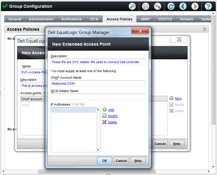
Figure 14-9 Dialog box to add the access policy details
6. Click Add to provide the IP addresses of the initiator ports that are intended to access the volume. CHAP authentication is optional and can be used, if required. For connecting a SAN Volume Controller or IBM Storwize controller, it is advised to use an IP address while creating the access policies. Therefore, you must add multiple IP addresses to one extended access point. Repeating this step for all of the initiator IP addresses creates a single extended access policy for all of the initiator IP addresses.
Figure 14-10 shows the added IP addresses of the IBM Storwize initiator.

Figure 14-10 Added IP addresses in the access policy
7. Click OK. You see the list of IP addresses that are added in the extended access point, as shown in Figure 14-11.

Figure 14-11 Window to review the new access policy details
8. Click OK. You see the newly created access policy in the Access Policies tab of the Group Configuration window, as shown in Figure 14-12.

Figure 14-12 Access policy creation completed
14.2.3 Creating volumes and applying access policies
To create the volume of Dell Equallogic PS Series Group, you might need to create a storage pool. You must use Dell product guidelines to plan the storage pools for better performance. The volumes can be created by using a default pool.
To create a volume, complete the following steps:
1. Open the Dell Equallogic PS Series Group Manager and go to the management IP address in a supported browser.

Figure 14-13 Creation of the volume on the Dell system
3. Provide the volume Name and an optional Description. You can optionally select the folder, select the needed storage pool, and click Next, as shown in Figure 14-14.

Figure 14-14 Providing Name, optional Description, and storage pool for volume
4. Specify the volume size. Select the check box if you want to create a thin-provisioned volume. Select a suitable snapshot reserve that is based on the requirement and Dell configuration guidelines, and click Next. Figure 14-15 shows a sample volume creation with the default pool and no thin provisioning.

Figure 14-15 Window to provide volume size and capacity saving details
5. Select the access policy for the volume. If you are planning to connect a Dell Equallogic PS Series system behind a SAN Volume Controller or Storwize cluster, it is advised that you should use the same access policies for all of the LUNs that are virtualized behind the SAN Volume Controller or IBM Storwize cluster. To create access policies, see 14.2.2, “Setting up access policies” on page 271. Select the Select or define access control policies radio button. Select the access policy that you want to apply on the volume and click Add, as shown in Figure 14-16.

Figure 14-16 Applying the access policy to volume
6. When you add the access policy, it is moved to the Selected box. Because each SAN Volume Controller node has an IQN, for one SAN Volume Controller or IBM Storwize cluster there are multiple iSCSI initiators. Therefore, you must enable simultaneous access to the volume from more than one iSCSI initiator by selecting Yes.
7. If you need default Dell controller settings, click Skip to end, as shown in Figure 14-17. Otherwise, select Next to change the sector size and specify the size that is recommended by Dell configuration guidelines for controller virtualization.

Figure 14-17 Allowing simultaneous access to more than one iSCSI initiator
8. Validate the summary and click Finish, as specified in Figure 14-18 to create the volume in the Dell controller.

Figure 14-18 Volume summary to validate before creation
Your volume is now created, and it can be viewed in the list of volumes. Figure 14-19 shows the created volume in the volume list. You can validate volume information in this window.

Figure 14-19 Dell volume details after volume creation
14.2.4 Modifying the settings of existing volumes
This section explains how to change the access policy mapping to the existing pre-created volume, and how to allow multiple iSCSI initiator access simultaneously. These steps are needed if you have a volume that is created on Dell Equallogic PS Series and you are planning online data migration to an SAN Volume Controller or IBM Storwize system. These settings also must be applied if you plan to use existing volumes for iSCSI-based virtualization with SAN Volume Controller or IBM Storwize systems.
Applying access policies on an existing volume
If you have a volume that is created on a Dell Equallogic PS Series system, and you are planning to change the access policies due to the reasons mentioned previously, complete the following steps to apply a new access policy on an existing volume. It is advised that you should remove older access policy mappings to prevent unwanted initiators from accessing the volume.
To apply the access policy on the volume, complete the following steps:
1. Open the Dell Equallogic PS Series Group manager by using the management IP address in a supported browser.
2. Select Volumes and click the volume name in the list. You see general volume information and volume space information in the window.

Figure 14-20 Window to add an access policy
4. Select the access policy that you want to apply on the volume. You can optionally create a new access policy by clicking New, which takes you to the access policy creation wizard that is described in 14.2.2, “Setting up access policies” on page 271. Click OK. The access policy is now applied to the volume. Figure 14-21 shows the access policy that is applied to the volume.

Figure 14-21 Selection of the access policy
5. To validate the access policy application, you must view the Access tab of the volume, as shown in Figure 14-22. This tab gives you information about the access policies for the selected volume. Other access policies can be added by clicking Add for access policies.

Figure 14-22 Window to validate access policy application
Allowing simultaneous access from multiple initiators
If you are planning to connect the Dell Equallogic PS Series volume to a SAN Volume Controller or IBM Storwize system, a SAN Volume Controller system has multiple iSCSI initiators. Due to this, the volume is accessed by multiple iSCSI initiators at the same time. You must perform the following steps for all the volumes that are supposed to be connected to a SAN Volume Controller or IBM Storwize system for migration or virtualization purposes.
If you must provide simultaneous access through multiple iSCSI initiators, complete the following steps:
1. Open the Dell Equallogic PS Series Group manager by using the management IP address in a supported browser.
2. Select Volumes and click the volume name in the list. You see general volume information and volume space information in the window.

Figure 14-23 Selection of the access type for the volume
4. Select the Allow simultaneous connections from initiators with different IQNs check box and click OK, as shown in Figure 14-24.

Figure 14-24 Enabling simultaneous access
14.3 Initiator configuration
This section deals with SAN Volume Controller system configuration and setting up iSCSI-attached storage with SAN Volume Controller or IBM Storwize Version 7.7.0 and later to virtualize Dell Equallogic PS Series. To virtualize Dell Equallogic PS Series, refer to 14.1, “Planning considerations” on page 266 before connecting Dell to the SAN Volume Controller or IBM Storwize systems. Before this step, users are expected to configure back-end storage by using the guidelines that are described in the previous sections of this chapter. In addition, it is assumed that the IQNs of the SAN Volume Controller or IBM Storwize initiators are added to the back-end system.
This section describes the initiator configuration while connecting a Dell Equallogic PS Series controller for migration or virtualization purpose through the iSCSI protocol. After you ensure that the target configuration is complete, the steps in this section must be followed to complete SAN Volume Controller or IBM Storwize initiators. This section is bifurcated into two subsections elaborating GUI and CLI configurations, respectively.
14.3.1 GUI workflow
When your target is configured and ready to connect, complete the following steps to connect Dell Equallogic PS Series to a SAN Volume Controller or IBM Storwize initiator system by using the GUI:
1. Log in to the SAN Volume Controller cluster user interface in a supported browser.
2. Check that the storage flags are enabled for all of the ports that you are planning for the Dell controller attachments. This information can be viewed in the Ethernet Ports window. Click Settings → Network → Ethernet ports and check for the Storage Port IPv4 or Storage Port IPv6, as shown in Figure 14-25. If ports are not enabled, follow the procedure that is described in 11.2.2, “Source port configuration” on page 220 to enable the storage ports.
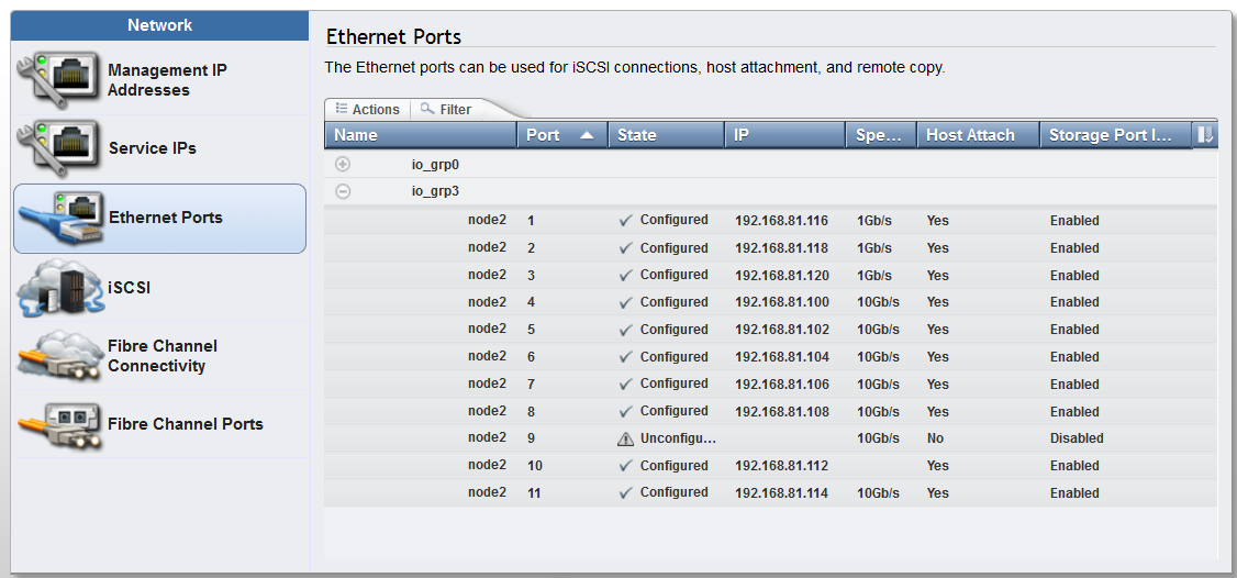
Figure 14-25 Storage flag settings GUI window
3. Click Pools → External Storage and click Add External iSCSI Storage. A dialog box displays prompts you to input the external storage controller type.
4. Select Dell and click Next, as shown in Figure 14-26. This action routes you to the Dell storage configuration wizard.

Figure 14-26 GUI dialog box for the selection of the controller type
5. Select the required I/O group from the drop-down menu options and provide the target IP address. Optionally, you can also specify a user name and CHAP secret. Specify the source ports from the drop-down list and click Next. Figure 14-27 provides an example of a completed form with all of the mentioned details.

Figure 14-27 Completed form for Dell Equallogic PS Series connection wizard
6. The list of discovered targets is displayed in a window with their respective IQNs and source ports. Figure 14-28 shows the sample window showing all of the discovered Dell LUNs.

Figure 14-28 Discovered LUNs from the Dell controller

Figure 14-29 Including LUNs for connection
8. After you click Include, click the drop-down list to select the source port from which you want to connect the target LUN and click OK. Figure 14-30 shows the selected port to connect the back-end LUN from where the back end is discovered.

Figure 14-30 Port selection window for back-end LUN connectivity
9. The LUN discovery window shows the included status and the appropriate port from where the LUN is included. In Figure 14-31, port 7 is selected to connect the back-end LUN. Perform this task for all of the LUNs that you are planning to include. Click Next to proceed.

Figure 14-31 Included LUN to connect from the initiator system
10. The summary of the included LUN is displayed in the summary window for validation, as shown in Figure 14-32. Click Finish after you review the summary. This action creates sessions to the specified LUNs of Dell controller.

Figure 14-32 Summary for back-end connection establishment
11. A set of commands run, and you see the task completion window indicting that the sessions are established from the initiator system to the target Dell controller.
12. To validate the added external storage controller, click Pools → External Storage. The newly added Dell Controller window opens, as shown in Figure 14-33. Click the plus sign (+) to see the MDisks that are associated with the controller and validate the correct status of the MDisks.

Figure 14-33 Added external Dell controller to the SAN Volume Controller system
After these steps are complete, you can use the added external Dell Equallogic PS Series controller for migration or virtualization purposes. The steps are the same as for external LUNs attached through Fibre Channel (FC): In the Pools → MDisks by Pools window, create a pool if necessary and add the managed disks to the pool (Figure 14-34).

Figure 14-34 MDisks from a Dell controller that is configured in a new pool
14.3.2 CLI workflows
This section provides information about configuring a Dell Equallogic PS Series storage system as an external iSCSI controller by using SAN Volume Controller or IBM Storwize CLI commands:
1. Log in to the SAN Volume Controller cluster command-line interface (CLI) by performing an SSH connection to the cluster IP address.
2. Check that the storage flags are enabled for all of the ports that you are planning for the Dell controller attachments, as shown in the lsportip CLI view in Example 14-1.
Example 14-1 The lspportip command output
IBM_2145:Redbooks_cluster1:superuser> svcinfo lsportip -delim ,
id,node_id,node_name,IP_address,mask,gateway,IP_address_6,prefix_6,gateway_6,MAC,duplex,state,speed,failover,link_state,host,remote_copy,host_6,remote_copy_6,remote_copy_status,remote_copy_status_6,vlan,vlan_6,adapter_location,adapter_port_id,lossless_iscsi,lossless_iscsi6,storage,storage_6
1,1,node1,,,,,,,08:94:ef:1b:bc:71,Full,unconfigured,1Gb/s,no,active,,0,,0,,,,,0,1,,,,
1,1,node1,,,,,,,08:94:ef:1b:bc:71,Full,unconfigured,1Gb/s,yes,active,,0,,0,,,,,0,1,,,,
2,1,node1,,,,,,,08:94:ef:1b:bc:72,Full,unconfigured,1Gb/s,no,active,,0,,0,,,,,0,2,,,,
2,1,node1,,,,,,,08:94:ef:1b:bc:72,Full,unconfigured,1Gb/s,yes,active,,0,,0,,,,,0,2,,,,
3,1,node1,,,,,,,08:94:ef:1b:bc:73,,unconfigured,,no,inactive,,0,,0,,,,,0,3,,,,
3,1,node1,,,,,,,08:94:ef:1b:bc:73,,unconfigured,,yes,inactive,,0,,0,,,,,0,3,,,,
4,1,node1,192.168.104.50,255.255.0.0,192.168.104.1,,,,40:f2:e9:e0:de:f4,Full,configured,10Gb/s,no,active,yes,0,,0,,,,,1,1,off,,yes,
4,1,node1,,,,,,,40:f2:e9:e0:de:f4,Full,configured,10Gb/s,yes,active,,0,,0,,,,,1,1,,,,
5,1,node1,192.168.104.51,255.255.0.0,192.168.104.1,,,,40:f2:e9:e0:de:f5,Full,configured,10Gb/s,no,active,yes,0,,0,,,,,1,2,off,,yes,
5,1,node1,,,,,,,40:f2:e9:e0:de:f5,Full,configured,10Gb/s,yes,active,,0,,0,,,,,1,2,,,,
6,1,node1,192.168.104.52,255.255.0.0,192.168.104.1,,,,40:f2:e9:e0:de:f6,,configured,,no,inactive,yes,0,,0,,,,,1,3,off,,yes,
6,1,node1,,,,,,,40:f2:e9:e0:de:f6,,configured,,yes,inactive,,0,,0,,,,,1,3,,,,
7,1,node1,192.168.104.53,255.255.0.0,192.168.104.1,,,,40:f2:e9:e0:de:f7,Full,configured,10Gb/s,no,active,yes,0,,0,,,,,1,4,off,,yes,
7,1,node1,,,,,,,40:f2:e9:e0:de:f7,Full,configured,10Gb/s,yes,active,,0,,0,,,,,1,4,,,,
1,3,node2,,,,,,,08:94:ef:1b:b6:29,Full,unconfigured,1Gb/s,no,active,,0,,0,,,,,0,1,,,,
1,3,node2,,,,,,,08:94:ef:1b:b6:29,Full,unconfigured,1Gb/s,yes,active,,0,,0,,,,,0,1,,,,
2,3,node2,,,,,,,08:94:ef:1b:b6:2a,Full,unconfigured,1Gb/s,no,active,,0,,0,,,,,0,2,,,,
2,3,node2,,,,,,,08:94:ef:1b:b6:2a,Full,unconfigured,1Gb/s,yes,active,,0,,0,,,,,0,2,,,,
3,3,node2,,,,,,,08:94:ef:1b:b6:2b,Full,unconfigured,1Gb/s,no,active,,0,,0,,,,,0,3,,,,
3,3,node2,,,,,,,08:94:ef:1b:b6:2b,Full,unconfigured,1Gb/s,yes,active,,0,,0,,,,,0,3,,,,
4,3,node2,192.168.104.54,255.255.0.0,192.168.104.1,,,,40:f2:e9:e0:03:c8,Full,configured,10Gb/s,no,active,yes,0,,0,,,,,1,1,off,,yes,
4,3,node2,,,,,,,40:f2:e9:e0:03:c8,Full,configured,10Gb/s,yes,active,,0,,0,,,,,1,1,,,,
5,3,node2,192.168.104.55,255.255.0.0,192.168.104.1,,,,40:f2:e9:e0:03:c9,Full,configured,10Gb/s,no,active,yes,0,,0,,,,,1,2,off,,yes,
5,3,node2,,,,,,,40:f2:e9:e0:03:c9,Full,configured,10Gb/s,yes,active,,0,,0,,,,,1,2,,,,
6,3,node2,192.168.104.56,255.255.0.0,192.168.104.1,,,,40:f2:e9:e0:03:ca,Full,configured,10Gb/s,no,active,yes,0,,0,,,,,1,3,off,,yes,
6,3,node2,,,,,,,40:f2:e9:e0:03:ca,Full,configured,10Gb/s,yes,active,,0,,0,,,,,1,3,,,,
7,3,node2,192.168.104.57,255.255.0.0,192.168.104.1,,,,40:f2:e9:e0:03:cb,Full,configured,10Gb/s,no,active,yes,0,,0,,,,,1,4,off,,yes,
7,3,node2,,,,,,,40:f2:e9:e0:03:cb,Full,configured,10Gb/s,yes,active,,0,,0,,,,,1,4,,,,
IBM_2145:Redbooks_cluster1:superuser>
If ports are not enabled for storage virtualization, you can use the cfgportip command to enable the ports for storage, as shown in Example 14-2.
Example 14-2 Using the cfgportip command to change the storage flag
IBM_2145:Redbooks_cluster1:superuser>
IBM_2145:Redbooks_cluster1:superuser>svctask cfgportip -node node1 -storage yes 7
IBM_2145:Redbooks_cluster1:superuser>
3. Discover the remote iSCSI targets by using the svctask detectiscsistorageportcandidate command, as shown in Example 14-3. Using this command, you can discover all of the iSCSI targets to which you are authorized to connect.
Example 14-3 The detectiscsistorageportcandidate CLI example
IBM_2145:Redbooks_cluster1:superuser>
IBM_2145:Redbooks_cluster1:superuser>svctask detectiscsistorageportcandidate -srcportid 7 -iogrp 0 -username Redbooks -chapsecret Redbooks12345 -targetip 192.168.104.100
IBM_2145:Redbooks_cluster1:superuser>
4. Confirm the discovered remote targets by using the svcinfo lsiscsistorageportcandidate command. This command shows all of the discovered Dell LUNs and their respective IQNs. Example 14-4 shows the Dell LUN that is discovered from I/O group 0 and its configured status as no, indicating that the connection to this LUN is not established.
Example 14-4 The lsiscsistorageportcandidate command example
IBM_2145:Redbooks_cluster1:superuser>lsiscsistorageportcandidate
id src_port_id target_ipv4 target_ipv6 target_iscsiname iogroup_list configured status site_id site_name
0 7 192.168.104.100 iqn.2001-05.com.equallogic:4-42a846-f1c8d8531-2170000303858d0f-volumerb 1:-:-:- no full
IBM_2145:Redbooks_cluster1:superuser>
5. After you decide to establish sessions with the targets, you can use the svctask addiscsistorageport command to add the targets to the SAN Volume Controller or
IBM Storwize system and make them appear as managed disks (MDisks). Example 14-5 shows the sample addiscsistorageport storage command. Because every Dell LUN has a different IQN, this command needs to be run for all of the LUN IDs listed in the addiscsistorageportcandidate output to which you want to connect.
IBM Storwize system and make them appear as managed disks (MDisks). Example 14-5 shows the sample addiscsistorageport storage command. Because every Dell LUN has a different IQN, this command needs to be run for all of the LUN IDs listed in the addiscsistorageportcandidate output to which you want to connect.
Example 14-5 The addiscsistorageport command example
IBM_2145:Redbooks_cluster1:superuser>
IBM_2145:Redbooks_cluster1:superuser>svctask addiscsistorageport -iogrp 0 -username Redbooks -chapsecret Redbooks12345 0
IBM_2145:Redbooks_cluster1:superuser>
6. View the iSCSI connection status by using the svcinfo lsiscsistorageport command, which provides the details of the iSCSI initiator connections. Example 14-6 shows how to verify the status of the established sessions by using the CLI.
Example 14-6 Status verification by using the lsiscsistorageport command
IBM_2145:Redbooks_cluster1:superuser>lsiscsistorageport
id src_port_id target_ipv4 target_ipv6 target_iscsiname controller_id iogroup_list status site_id site_name
0 7 192.168.104.100 iqn.2001-05.com.equallogic:4-42a846-f1c8d8531-2170000303858d0f-volumerb 1 1:-:-:- full
IBM_2145:Redbooks_cluster1:superuser>
IBM_2145:Redbooks_cluster1:superuser>lsiscsistorageport 0
id 0
src_port_id 7
target_ipv4 192.168.104.100
target_ipv6
target_iscsiname iqn.2001-05.com.equallogic:4-42a846-f1c8d8531-2170000303858d0f-volumerb
controller_id 1
iogroup_list 1:-:-:-
status full
site_id
site_name
node_id 1
node_name node1
src_ipv4 192.168.104.53
src_ipv6
src_iscsiname iqn.1986-03.com.ibm:2145.redbookscluster1.node1
connected yes
node_id 3
node_name node2
src_ipv4 192.168.104.57
src_ipv6
src_iscsiname iqn.1986-03.com.ibm:2145.redbookscluster1.node2
connected yes
IBM_2145:Redbooks_cluster1:superuser>
7. Optionally, you can run the svctask detectmdisk command on the SAN Volume Controller or IBM Storwize system that you are trying to virtualize from to detect any LUNs that are exported to the system from the external controller, as shown in Example 14-7.
Example 14-7 Discovering the storage at the initiator
IBM_2145:Redbooks_cluster1:superuser>svctask detectmdisk
8. You can then run the svcinfo lsmdisk command to list discovered storage. Example 14-8 shows the iSCSI attached MDisk upon a successful Dell external controller addition.
Example 14-8 Concise and detailed view of MDisks listing the iSCSI-related fields
IBM_2145:Redbooks_cluster1:superuser>lsmdisk
id name status mode mdisk_grp_id mdisk_grp_name capacity ctrl_LUN_# controller_name UID tier encrypt site_id site_name distributed dedupe
0 mdisk0 online managed 0 mdiskgrp0 200.0GB 0000000000000000 controller0 600a0b800068b0ca0000128f559c826100000000000000000000000000000000 tier_enterprise no no no
1 mdisk1 online managed 0 mdiskgrp0 200.0GB 0000000000000001 controller0 600a0b800068b0ca00001292559c827f00000000000000000000000000000000 tier_enterprise no no no
3 mdisk3 online unmanaged 100.0GB 0000000000000000 controller1 64842a1453d8c8f10f8d85030300702100000000000000000000000000000000 tier_enterprise no no no
IBM_2145:Redbooks_cluster1:superuser>
IBM_2145:Redbooks_cluster1:superuser>lsmdisk 3
id 3
name mdisk3
status online
mode unmanaged
mdisk_grp_id
mdisk_grp_name
capacity 100.0GB
quorum_index
block_size 512
controller_name controller1
ctrl_type 4
ctrl_WWNN
controller_id 1
path_count 2
max_path_count 2
ctrl_LUN_# 0000000000000000
UID 64842a1453d8c8f10f8d85030300702100000000000000000000000000000000
preferred_WWPN
active_WWPN
fast_write_state empty
raid_status
raid_level
redundancy
strip_size
spare_goal
spare_protection_min
balanced
tier tier_enterprise
slow_write_priority
fabric_type iscsi
site_id
site_name
easy_tier_load medium
encrypt no
distributed no
drive_class_id
drive_count 0
stripe_width 0
rebuild_areas_total
rebuild_areas_available
rebuild_areas_goal
dedupe no
preferred_iscsi_port_id 0
active_iscsi_port_id 0
replacement_date
IBM_2145:Redbooks_cluster1:superuser>
9. View the discovered external iSCSI-attached controllers by using the svctask lscontroller command. A detailed view shows the protocol by which the controller is attached to the system, as shown in Example 14-9.
Example 14-9 Listing the discovered external Dell controller
IBM_2145:Redbooks_cluster1:superuser>lscontroller 1
id 1
controller_name controller1
WWNN
mdisk_link_count 1
max_mdisk_link_count 1
degraded no
vendor_id EQLOGIC
product_id_low 100E-00
product_id_high
product_revision 9.0
ctrl_s/n f3fba8e3
allow_quorum no
fabric_type iscsi
site_id
site_name
WWPN
path_count 2
max_path_count 2
iscsi_port_id 0
ip 192.168.104.100
IBM_2145:Redbooks_cluster1:superuser>
Now, you can configure the Dell LUNs that are mapped to the cluster of initiator nodes as managed disks in the SAN Volume Controller or IBM Storwize system. The steps are the same as for external LUNs attached through FC. Using the mkmdiskgrp CLI command, you can create a pool, if necessary, and add the managed disks to the pool (Example 14-10).
Example 14-10 The mkmdiskgrp command
IBM_2145:Redbooks_cluster1:superuser> svctask mkmdiskgrp -ext 1024 -mdisk mdisk3 -name Pool_Dell
MDisk Group, id [0], successfully created
IBM_2145:Redbooks_cluster1:superuser>
..................Content has been hidden....................
You can't read the all page of ebook, please click here login for view all page.