


Preinstallation planning and sizing
This chapter provides information to help you plan the installation and implementation of the IBM TS7700.
This chapter includes the following topics:
|
Remember: For this chapter, the term tape library refers to the IBM TS3500 and TS4500 tape libraries.
|
4.1 Hardware installation and infrastructure planning
This section describes planning information that is related to your TS7700. The topics that are covered include system requirements and infrastructure requirements. Figure 4-1 shows an example of the connections and infrastructure resources that might be used for a TS7700 grid configuration with two separate data centers.

Figure 4-1 TS7700 grid configuration example
The letters in Figure 4-1 refer to the following items:
•A: TS7740/TS7720T/TS7760T – 3584-L23 library control frame
TS7760T – 3584-L25 library control frame
•B: TS7740/TS7720T/TS7760T – 3584-D23 frames with 3592, TS1120, TS1130, TS1140, or TS1150 drives, 3584-S24 HD storage frames
TS7760T – 3584-D25 frames with TS1140 or TS1150 drives, 3584-S25 storage frames
•C: TS7740/TS7720T/TS7760T – 3584-HA1 frame and 3584-D23/HA frame (optional)
•D: TS7740/RS7720T/TS7760T – 3592 Advanced media type JA/JB/JC/JD and 3592 Advanced Economy media type JJ/JK/JL data cartridges for the data repository
TS7760T – 3592 Advanced media type JA/JB/JC/JD and 3592 Advanced Economy media type JJ/JK/JL data cartridges for the data repository
•F: Total Storage System Console (TSSC) for IBM Service Support Representatives
(IBM SSRs) and Autonomic Ownership Takeover Manager (AOTM)
(IBM SSRs) and Autonomic Ownership Takeover Manager (AOTM)
•G: TS7700
•H: TS7740/TS7720 – two or four 1 Gb Ethernet (copper or SW fibre) or two 10 Gb Ethernet for Grid communication
TS7760 – two or four 1 Gb Ethernet (copper or SW fibre) or two or four 10 Gb Ethernet for Grid communication
•I: Ethernet connections for Management Interfaces (MIs)
•J: TS7740/TS7720 – FICON connections for host workload, two - four 4 Gb or two - eight
8 Gb
8 Gb
TS7760 - FICON connections for host workload, two - eight 8 Gb or two - eight 16 Gb
•K: FICON fabric infrastructure with extension technology when appropriate
4.1.1 System requirements
Ensure that your facility meets the system requirements for the TS7700 when you plan for installation. System requirements for installation include requirements for power, cooling, floor leveling, loading, distribution, clearance, environmental conditions, and acoustics.
For more information about system requirements, see IBM TS7700 R4.2 at IBM Knowledge Center:
IBM 3952 Tape Frame specifications
The 3952 Tape Frame F05 houses the components of the TS7720 and TS7740, while 3952 F06 houses the components of the TS7760. Table 4-1 lists the dimensions of the frame that encloses the TS7700.
Table 4-1 Physical characteristics of a maximally configured 3952 Tape Frame
|
Characteristic
|
3952 F05
|
3952 F06Value
|
|
Height
|
1804 mm (71.0 in.)
|
1930.4 mm (76 in.)
|
|
Width
|
644 mm (25.4 in.)
|
616 mm (24.25 in.)
|
|
Depth
|
1098 mm (43.23 in.)
|
Closed doors:
1425 mm (56.1 in.)
Open doors (both front/rear):
2515 mm (99 in.)
|
|
Weight
|
270 kg (595.25 lb.) empty
669.1 kg (1475 lb.) maximally configured
|
746 kg (1645 lb.) maximally configured
|
|
Power
|
240 Vac, 15 amp (single phase)
|
240 Vac, 15 amp (single phase)
|
|
Unit height
|
36 U
|
40 U
|
Environmental operating requirements
Your facility must meet specified temperature and humidity requirements before you install the TS7700. Table 4-2 lists the preferred environmental conditions for the TS7700.
Table 4-2 Environmental specifications
|
Condition
|
Air temperature
|
Altitude
|
Relative humidity1
|
Wet bulb temperature
|
|
Operating
(low altitude) |
10°C - 32°C (50°F - 89.6°F)
|
Up to 5000 ft. above mean sea level (AMSL)
|
20% - 80%
|
23°C (73°F)
|
|
Operating
(high altitude) |
10°C - 28°C (50°F - 82.4°F)
|
5001 ft. AMSL - 7000 ft. AMSL
|
20% - 80%
|
23°C (73°F)
|
|
Preferred operating range2
|
20°C - 25°C (68°F - 77°F)
|
Up to 7000 ft. AMSL
|
40% - 55%
|
N/A
|
|
Power off
|
10°C - 43°C (50°F - 109°F)
|
N/A
|
8% - 80%
|
27°C (80°F)
|
|
Storage
|
1°C - 60°C (33.8°F - 140°F)
|
N/A
|
5% - 80%
|
29°C (84°F)
|
|
Shipping
|
-40°C - 60°C (-40°F - 140°F)
|
N/A
|
5% - 100%
|
29°C (84°F)
|
1 Non-condensing
2 Although the TS7700 can operate outside this range, it is advised that you adhere to the preferred operating range.
Power considerations
Your facility must have ample power to meet the input voltage requirements for the TS7700.
The standard 3952 Tape Frame includes one internal power distribution unit. However, feature code 1903, Dual AC power, is required to provide two power distribution units to support the high availability (HA) characteristics of the TS7700. The 3952 Storage Expansion Frame has two power distribution units and requires two power feeds.
TS7720 Base Frame power requirements
Your facility must have ample power to meet the input voltage requirements for the TS7720 Base Frame. Table 4-3 lists the maximum input power for a fully configured TS7720 Base Frame.
Table 4-3 TS7720 Base Frame maximum input power requirements
|
Power requirement
|
Value
|
|
Voltage
|
200 - 240 V AC (single phase)
|
|
Frequency
|
50 - 60 Hz (+/- 3 Hz)
|
|
Current
|
20 A
|
|
Inrush current
|
250 A
|
|
Power (W)
|
3,140 W
|
|
Input power required
|
4.0 kVA (single phase)
|
|
Thermal units
|
11.0 KBtu/hr, 2.76 kcal/hr
|
TS7720 Storage Expansion Frame power requirements
Your facility must have ample power to meet the input voltage requirements for the TS7720 Storage Expansion Frame. Table 4-4 lists the maximum input power for a fully configured TS7720 Expansion Frame.
Table 4-4 TS7720 Storage Expansion Frame maximum input power requirements
|
Power requirement
|
Value
|
|
Voltage
|
200 - 240 V AC (single phase)
|
|
Frequency
|
50 - 60 Hz (+/- 3 Hz)
|
|
Current
|
20 A
|
|
Inrush current
|
250 A
|
|
Power (W)
|
3,460 W
|
|
Input power required
|
4.0 kVA (single phase)
|
|
Thermal units
|
11.8 KBtu/hr, 2.96 kcal/hr
|
TS7740 Base Frame power requirements
Your facility must have ample power to meet the input voltage requirements for the TS7740 Base Frame. Table 4-5 lists the maximum input power for a fully configured TS7740 Base Frame.
Table 4-5 TS7740 Base Frame maximum input power requirements
|
Power requirement
|
Value
|
|
Voltage
|
200 - 240 V AC (single phase)
|
|
Frequency
|
50 - 60 Hz (+/- 3 Hz)
|
|
Current
|
20 A
|
|
Inrush current
|
250 A
|
|
Power (W)
|
1786 W
|
|
Input power required
|
4.0 kVA (single phase)
|
|
Thermal units
|
6.05 kBtu/hr, 1.52 kcal/hr
|
TS7760 Base Frame power requirements
Your facility must have ample power to meet the input voltage requirements for the TS7760 Base Frame. Table 4-6 lists the maximum input power for a fully configured TS7760.
Table 4-6 TS7760 Base Frame maximum input power requirements
|
Power requirement
|
Value
|
|
Voltage
|
200 - 240 V AC (single phase)
|
|
Frequency
|
50 - 60 Hz (+/- 3 Hz)
|
|
Current
|
24 amp
|
|
Inrush current
|
250 amp
|
|
Power (W)
|
3280 watts
|
|
Input power required
|
4.8 kVa (single phase)
|
|
Thermal units
|
11.5 kBtu/hr, 2.9 kcal/hr
|
TS7760 Storage Expansion Frame power requirements
Your facility must have ample power to meet the input voltage requirements for the TS7760 Storage Expansion Frame. Table 4-7 lists the maximum input power for a fully configured TS7760.
Table 4-7 TS7760 Storage Expansion Frame maximum input power requirements
|
Power requirement
|
Value
|
|
Voltage
|
200 - 240 V AC (single phase)
|
|
Frequency
|
50 - 60 Hz (+/- 3 Hz)
|
|
Current
|
24 amp
|
|
Leakage current
|
13.5 ma
|
|
Inrush current
|
250 amp
|
|
Power (W)
|
3200 watts
|
|
Input power required
|
4.8 kVa (single phase)
|
|
Thermal units
|
11.2 kBtu/hr, 2.9 kcal/hr
|
Tape drives and media support (TS7740,TS7720T, and TS7760T)
The TS7740, TS7720T, and TS7760T support the 3592 Tape Cartridge (JA), 3592 Expanded Capacity Cartridge (JB), 3592 Advanced Tape Cartridge (JC), 3532 Advanced Data Tape Cartridge (JD), 3592 Economy Tape Cartridge (JJ), 3592 Economy Advanced Tape Cartridge (JK) media, and 3592 Economy Tape Cartridge (JL).
The TS7740, TS7720T, and TS7760T support the 3592 Extended Tape Cartridge (JB) media and require TS1120 model E05 Tape Drives in E05 mode, TS1130 Model E06/EU6 tape drives, TS1140 Model E07 or EH7 tape drives. Alternatively, they require a heterogeneous setup involving the TS1150 Model E08 or EH8 tape drives and either of the TS1120 Model E05, TS1130 Model E06/EU6, or TS1140 Model E07 or EH7 tape drives, depending on the library generation.
In a TS3500 tape library, all tape drives and media are supported. In a TS4500 tape library, only TS1140 and TS1150 with the corresponding media is supported.
The TS7740, TS7720T, and TS7760T tape encryption (FC 9900) require that all the backend drives be encryption capable. TS1130 Model E06/EU6, TS1140 Model E07 or EH7, and TS1150 Model E08 or EH8 drives are encryption capable. TS1120 Model E05 Tape Drives in E05 mode are encryption capable, with either FC 9592 from the factory, or FC 5592 as a field upgrade.
Support for the fourth generation of the 3592 drive family is included in TS7700 Release 2.0 PGA1. At this code level, the TS1140 tape drive that is attached to a TS7740 and TS7720T cannot read JA or JJ media. Ensure that data from all JA and JJ media has been migrated to JB media before you replace older-generation tape drives with TS1140 drives. Starting with Release 2.1 PGA0 the reading of JA and JJ media by the TS1140 drive is supported. The client can choose to keep the data on the JA/JJ media or can plan to migrate the data to newer generations of media.
Heterogeneous Tape Drive Support
Starting with release R3.3, the TS7740 and TS7720 Tape attach supports Heterogeneous Tape Drives. Heterogeneous Tape Drives are also supported by TS7760T and release R4.0 or later.
TS1150 tape drives can be intermixed with some other drive types. The E08 drives are supported in a limited heterogeneous configuration.
The new media types JD and JL are supported by the TS7700. Up to 10 TB of data can be written to the JD cartridge in the 3593 E08 tape drive recording format. Up to 2 TB of data can be written to the JL cartridge in the 3592 E08 tape drive recording format. The 3592 E08 tape drive also supports writing to prior generation media types JK and JC. When the 3592 E08 recording format is used starting at the beginning of tape, up to 7 TB of data can be written to a JC cartridge and up to 900 GB of data can be written to a JK cartridge.
The 3592 E08 tape drive does not support reading or writing to media type JJ, JA, and JB cartridges. The TS7700 does not support any type of Write Once Read Many (WORM) physical media.
|
Important: Not all cartridge media types and media formats are supported by all 3592 tape drive models. For the media, format, and drive model compatibility to see which tape drive model is required for a certain capability (see Table 4-8).
|
Table 4-8 Supported 3592 read/write formats
|
3592
Tape Drive
|
EFMT1
512 tracks,
8 R/W channels
|
EFMT2
896 tracks,
16 R/W channels
|
EFMT3
1152 tracks,
16 R/W channels
|
EFMT4
664 tracks (JB/JX)
2176 tracks (JC/JK),
32 R/W channels
|
EFMT5
4608 tracks (JC/JK)
5120 tracks (JD/JL),
32 R/W channels
|
|
Model J1A
|
Read/write
|
Not supported
|
Not supported
|
Not supported
|
Not supported
|
|
Model E05
|
Read/write1
|
Read/write
|
Not supported
|
Not supported
|
Not supported
|
|
Model E06/EU6
|
Read
|
Read/write
|
Read/write
|
Not supported
|
Not supported
|
|
Model E07/EH7
|
Read2
|
Readb
|
Read/write3
|
Read/write
|
Not supported
|
|
Model E08/EH8
|
Not supported
|
Not supported
|
Not supported
|
Read/write
|
Read/write
|
1 Model E05 can read and write EFMT1 operating in native or J1A emulation mode.
2 Model E07/EH7 can read JA and JJ cartridge types only with a tape drive firmware level of D3I3_5CD or higher.
3 Cartridge type JB only.
Table 4-9 lists the tape drive models, capabilities, and supported media by tape drive model.
Table 4-9 3592 Tape Drive models and characteristics versus supported media and capacity
|
3592 drive type
|
Supported media type
|
Encryption support
|
Capacity
|
Data rate
|
|
TS1150 Tape Drive
(3592-E08/EH8 Tape Drive)
|
JC
JD
JK
JL
|
Yes
|
7 TB (JC native)
10.0 TB (JD native)
900 GB (JK native)
2 TB (JL native)
10.0 TB (maximum all)
|
360 MBps
|
|
TS1140 Tape Drive
(3592-E07/EH7 Tape Drive)
|
JB
JC
JK
Media read only:
JA
JJ
|
Yes
|
1.6 TB (JB native)
4.0 TB (JC native)
500 GB (JK native)
4.0 TB (maximum all)
|
250 MBps
|
|
TS1130 Tape Drive
(3592-EU6 or 3592-E06 Tape Drive)
|
JA
JB
JJ
|
Yes
|
640 GB (JA native)
1.0 TB (JB native)
128 GB (JJ native)
1.0 TB (maximum all)
|
160 MBps
|
|
TS1120 Tape Drive
(3592-E05 Tape Drive)
|
JA
JB
JJ
|
Yes
|
500 GB (JA native)
700 GB (JB native)
100 GB (JJ native)
700 GB (maximum all)
|
100 MBps
|
|
3592-J1A
|
JA
JJ
|
No
|
300 GB (JA native)
60 GB (JJ native)
300 GB (maximum all)
|
40 MBps
|
|
Notes:
•To use tape encryption, all drives that are associated with the TS7740, TS7720T, or TS7760T must be Encryption Capable and encryption-enabled.
•Encryption is not supported on 3592 J1A tape drives.
|
||||
The media type is the format of the data cartridge. The media type of a cartridge is shown by the last two characters on standard bar code labels. The following media types are supported:
•JA: An Enterprise Tape Cartridge (ETC)
A JA cartridge can be used in native mode in a 3592-J1A drive or a 3592-E05 Tape Drive operating in either native mode or J1A emulation mode. The native capacity of a JA tape cartridge that is used in a 3592-J1A drive or a 3592-E05 Tape Drive in J1A emulation mode is 300 GB, equivalent to 279.39 gibibytes (GiB). The native capacity of a JA tape cartridge that is used in a 3592-E05 Tape Drive in native mode is 500 GB (465.6 GiB). The native capacity of a JA tape cartridge that is used in a 3592-E06 drive in native mode is 640 GB (596.04 GiB).
•JB: An Enterprise Extended-Length Tape Cartridge (ETCL)
Use of JB tape cartridges is supported only with TS1140 Tape Drives, TS1130 Tape Drives, and TS1120 Tape Drives operating in native capacity mode. When used with TS1140 Tape Drives, JB media that contains data that is written in native E05 mode is only supported for read-only operations.
After this data is reclaimed or expired, the cartridge can be written from the beginning of the tape in the new E07 format. If previously written in the E06 format, appends are supported by the TS1140 drive.
The native capacity of a JB tape cartridge that is used in a 3592-E05 drive is 700 GB
(651.93 GiB). When used in a 3592-E06 drive, the JB tape cartridge native capacity is 1000 GB (931.32 GiB). When used within a Copy Export pool, a JB tape cartridge can be written in the E06 format with a TS1140 drive, enabling Copy Export restores to occur with TS1130 hardware. The native capacity of JB media that are used in a 3592-E07 tape drive in native mode is 1600 GB (1490.12 GiB).
(651.93 GiB). When used in a 3592-E06 drive, the JB tape cartridge native capacity is 1000 GB (931.32 GiB). When used within a Copy Export pool, a JB tape cartridge can be written in the E06 format with a TS1140 drive, enabling Copy Export restores to occur with TS1130 hardware. The native capacity of JB media that are used in a 3592-E07 tape drive in native mode is 1600 GB (1490.12 GiB).
•JC: Advanced Type C Data (ATCD)
This media type is supported for use with TS1150 and TS1140 tape drives. The native capacity of JC media that is used in a 3592-E07 drive is 4 TB (3.64 TiB) and in a 3592-E08 drive is 7 TB (6.52 TiB).
•JD: Advanced Type D Data (ATDD)
This media type is supported for use only with TS1150 tape drives.
•JJ: An Enterprise Economy Tape Cartridge (EETC)
A JJ cartridge can be used in native mode in a 3592-J1A drive or a 3592-E05 Tape Drive operating in either native mode or J1A emulation mode. The native capacity of a JJ tape cartridge that is used in a 3592-J1A drive or 3592-E05 Tape Drive in J1A emulation mode is 60 GB (58.88 GiB). The native capacity of a JJ tape cartridge that is used in a 3592-E05 Tape Drive in native mode is 100 GB (93.13 GiB). A JJ cartridge can be used in native mode in a 3592-J1A drive or a 3592-E05 Tape Drive operating in either native mode or J1A emulation mode.
•JK: Advanced Type K Economy (ATKE)
This media type is supported for use only with TS1150 and TS1140 tape drives.
•JL: Advanced Type L Economy (ATLE)
This media type is supported for use only with TS1150 tape drives.
The following media identifiers are used for diagnostic and cleaning cartridges:
•CE: Customer Engineer diagnostic cartridge for use only by IBM SSRs. The VOLSER for this cartridge is CE xxxJA, where a space occurs immediately after CE and xxx is three numerals.
•CLN: Cleaning cartridge. The VOLSER for this cartridge is CLN xxxJA, where a space occurs immediately after CLN and xxx is three numerals.
Planning for a TS7740, TS7720T, or TS7760T tape drive model change
|
Important: WORM cartridges, including JW, JR, JX, JY, and JZ, are not supported. Capacity scaling of 3592 tape media is also not supported by TS7740, TS7720T, and TS7760T.
|
When you change the model of the 3592 tape drives of an existing TS7740, TS7720T or TS7760T, the change must be in the later version direction, from an older 3592 tape drive model to a newer 3592 tape drive model.
3592 E08 drives can be mixed with one other previous generation tape drive through heterogeneous tape drive support, which allows a smooth migration of existing TS7700 tape drives with older tape drives to TS1150 tape drives.
For more information, see 7.2.6, “Upgrading drive models in an existing TS7740 or TS7700T” on page 279.
4.1.2 TS7700 specific limitations
Consider the following restrictions when you perform your TS7700 preinstallation and planning:
•Cloud Storage Tier capabilities can only be enabled in a TS7760 that is not attached to a physical tape library.
•Cloud Storage Tier requires that the server in the target TS7760 installed more 32 GB of RAM memory (Feature Code 3466) to reach a total of 64 GB available.
•Release 4.2 is supported on models 3957-V07, 3957-VEB, and 3957-VEC only.
•Existing supported machines can be upgraded to install Release 4.2 only if they have Version 3.3 or later installed.
•TS1120 Tape Drives set in static emulation mode are not supported by the TS7740, TS7720T, and TS7760T. Static emulation mode forces the 3592-E05 to operate as a 3592-J1A drive.
•The maximum FICON cable distance for a direct connection between a TS7700 and host processor using short wavelength attachments at the 4 Gbps speed is up to 150 meters using 50 micron fiber cable, and up to 55 meters using 62.5 micron fiber.
•At 8 Gbps speed, the short wave total cable length cannot exceed the following measurements:
– 150 meters using 50 micron OM3 (2000 MHz*km) Aqua blue colored fiber.
– 50 meters using 50 micron OM2 (500 MHz*km) Orange colored fiber.
– 21 meters using 62.5 micron OM1 (200 MHz*km) Orange colored fiber.
•At 16 Gbps speed, the short wave total cable length cannot exceed the following measurements:
– 130 meters using 50 micron OM4 (4700 MHz*km) Aqua blue colored fiber.
– 100 meters using 50 micron OM3 (2000 MHz*km) Aqua blue colored fiber.
– 35 meters using 50 micron OM2 (500 MHz*km) Orange colored fiber.
•Long wavelength attachments (4 Gb, 8 Gb, or 16 Gb) provide a direct link of up to 10 km between the TS7700 and host processor on 9-micron fiber.
•Short and long wavelength attachments provide for up to 100 km between the TS7700 and host processor using appropriate fiber switches, and up to 250 km with DWDMs. Support is not provided through more than one dynamic switch.
For more information about Ficon connectivity, see IBM Z Connectivity Handbook, SG24-5444.
•The maximum length of the Cat 5e or Cat 6 cable between the grid Ethernet adapters in the TS7700 and the customer’s switches or routers is 100 meters.
•The TS7700 does not support capacity scaling of 3592 tape media.
•The TS7700 does not support physical WORM tape media.
•The TS3500/TS4500 and TS7700 must be within 100 feet of the TSSC.
•The 3592 back-end tape drives for a TS7740, TS7720T, or TS7760T cluster must be installed in a TS3500 or TS4500 tape library.
•The TS7740 and TS7720T support 4 Gb, 8 Gb, or 16 Gb fiber switches for connection to the back-end drives.
•TS7760T can only be connected to backend tape drives through 16 Gb fiber switches
•Clusters that are running Release 4.2 code level can be joined only in a grid with clusters that are running Release 2.1 or later. Release 4.2 supports up to three different code levels within the same grid. This situation can happen when grids are composed of clusters V06/VEA intermixed with clusters V07/VEB/VEC within the same grid. TS7700 cluster models V06/VEA are not compatible with LIC R4.2, and must stay at Release 2.1 or Release 3.0.
|
Note: Existing TS7700 (3957-V06 with 3956-CC7 or 3956-CC8, 3957-VEA, 3957-V07, or 3957-VEB) can be upgraded to Release 3.0. To upgrade to Release 3.0, the existing cluster must be at least at 8.20.x.x (R2.0) level or later. Upgrade from 8.7.x.x (R1.7) level to Release 3.0 is only supported by RPQ.
3957-V06 with 3956-CC6 is not supported by Release 3.0.
|
•For this reason, during the code upgrade process, one grid can have clusters that are simultaneously running three different levels of code. Support for three different levels of code is available on a short-term basis (days or a few weeks), which should be long enough to complete the Licensed Internal Code upgrade in all clusters in a grid. The support for two different levels of code in a grid enables an indefinite coexistence of V06/VEA and V07/VEB/VEC clusters within the same grid.
•Because one new cluster can be joined in an existing grid with clusters that are running up to two different code levels, the joining cluster must join to a target cluster at the higher of the two code levels. Merging of clusters with mixed code levels is not supported.
•The grid-wide functions available to a multi-cluster grid are limited by the lowest code level present in that grid.
4.1.3 TCP/IP configuration considerations
The Transmission Control Protocol/Internet Protocol (TCP/IP) configuration considerations and local area network/wide area network (LAN/WAN) requirements for the TS7700 are described in the following sections. Single and multi-cluster grid configurations are covered.
Figure 4-2 shows you the different networks and connections that are used by the TS7700 and associated components. This two-cluster TS7740/TS7720T/TS7760T grid shows the TS3500 and TS4500 tape library connections (not present in a TS7720D and TS7760D configuration).

Figure 4-2 TCP/IP connections and networks
TS7700 grid and cloud LAN/WAN requirements
The LAN/WAN requirements for the TS7700 cross-site grid Internet Protocol network infrastructure are described in this section.
The TS7700 grid IP network infrastructure must be in place before the grid is activated so that the clusters can communicate with one another as soon as they are online. Two or four 1-GbE or 10-GbE connections must be in place before grid installation and activation.
An Ethernet extender or other extending equipment can be used to complete extended distance Ethernet connections.
Extended grid Ethernet connections can be any of the following connections:
•1 Gb copper 10/100/1000 Base-TX
This adapter conforms to the Institute of Electrical and Electronics Engineers (IEEE) 802.3ab 1000Base-T standard, which defines gigabit Ethernet operation over distances up to 100 meters by using four pairs of CAT6 copper cabling.
•1 Gb optical SW
This SX adapter has an LC Duplex connector that attaches to 50-micron (µ) or 62.5-µ multimode fiber cable. It is a standard SW, 850-nanometer (nm) adapter that conforms to the IEEE 802.3z standards. This adapter supports distances of 2 - 260 meters for 62.5-µ multimode fiber (MMF) and 2 - 550 meters for 50.0-µ MMF.
•10 Gb optical LW
This 10 Gb grid optical LW connection provides single or dual port options, 10-Gbps Ethernet LW adapter for grid communication between TS7700 tape systems. This adapter has an LC Duplex connector for attaching 9-µ, single-mode fiber cable. This is a standard LW (1310 nm) adapter that conforms to the IEEE 802.3ae standards. It supports distances up to 10 kilometers (km), equivalent to 6.21 miles.
The default configuration for a R4.2 TS7700 server from manufacturing (3957-VEC) is two dual-ported PCIe 1-GbE adapters. You can use FC 1038, 10 Gb dual port grid optical LW connection to choose support for two 10 Gb optical LW Ethernet adapters instead.
If the TS7700 server is a 3957-V07, 3957-VEB or 3957-VEC, two instances of either FC 1036 (1 Gb grid dual port copper connection) or FC 1037 (1 Gb dual port optical SW connection) must be installed. You can use FC 1034 to activate the second port on dual-port adapters.
Clusters that are configured by using four 10-Gb, two 10-Gb, four 1-Gb, or two 1-Gb clusters, can be interconnected within the same TS7700 grid, although the explicit same port-to-port communications still apply.
|
Important: Identify, order, and install any new equipment to fulfill grid installation and activation requirements. The connectivity and performance of the Ethernet connections must be tested before grid activation. You must ensure that the installation and testing of this network infrastructure is complete before grid activation.
To avoid performance issues, the network infrastructure should not add packet metadata (increase its size) to the default 1500-byte maximum transmission unit (MTU), such as with an encryption device or extender device.
|
The network between the TS7700 clusters in a grid must have sufficient bandwidth to account for the total replication traffic. If you are sharing network switches among multiple TS7700 paths or with other devices, the total bandwidth of the network must be sufficient to account for all of the network traffic.
|
Consideration: Jumbo Frames are not supported.
|
The TS7700 uses TCP/IP for moving data between each cluster. Bandwidth is a key factor that affects inter-cluster throughput for the TS7700. The following key factors can also affect throughput:
•Latency between the TS7700 clusters
•Network efficiency (packet loss, packet sequencing, and bit error rates)
•Network switch capabilities
•Flow control to pace the data from the TS7700 tape drives
•Inter-switch link capabilities (flow control, buffering, and performance)
The TS7700 clusters attempt to drive the grid network links at the full speed that is allowed by the adapter (1 Gbps or 10 Gbps rate), which might exceed the network infrastructure capabilities. The TS7700 supports the IP flow control frames so that the network paces the level at which the TS7700 attempts to drive the network. The preferred performance is achieved when the TS7700 can match the capabilities of the underlying grid network, resulting in fewer dropped packets.
|
Remember: When the grid network capabilities are below TS7700 capabilities, packets are lost. This causes TCP to stop, resync, and resend data, resulting in a less efficient use of the network. Flow control helps to reduce this behavior. 1-Gb and 10-Gb clusters can be within the same grid, but compatible network hardware must be used to convert the signals because 10 Gb cannot negotiate down to 1 Gb.
Note: It is advised to enable flow control in both directions to avoid grid link performance issues.
|
To maximize throughput, ensure that the underlying grid network meets these requirements:
•Has sufficient bandwidth to account for all network traffic that is expected to be driven through the system to eliminate network contention.
•Can support the flow control between the TS7700 clusters and the switches, which enables the switch to pace the TS7700 to the WAN capability. Flow control between the switches is also a potential factor to ensure that the switches can pace their rates to one another. The performance of the switch should be capable of handling the data rates that are expected from all of the network traffic.
Latency can be defined as the time interval elapsed between a stimulus and a response. In the network world, latency can be understood as how much time it takes for a data package to travel from one point to another in a network infrastructure. This delay is introduced by some factors, such as the electronic circuitry used in processing the data signals, or plainly by the universal physics constant, the speed of light. Considering the current speed of data processing, this is the most important element for an extended distance topology.
In short, latency between the sites is the primary factor. However, packet loss due to bit error rates or insufficient network capabilities can cause TCP to resend data, which multiplies the effect of the latency.
The TS7700 uses clients LAN/WAN to replicate virtual volumes, access virtual volumes remotely, and run cross-site messaging. The LAN/WAN must have adequate bandwidth to deliver the throughput necessary for your data storage requirements.
The cross-site grid network is 1 GbE with either copper (RJ-45) or SW fiber (single-ported or dual-ported) links. For copper networks, CAT5E or CAT6 Ethernet cabling can be used, but CAT6 cabling is preferable to achieve the highest throughput. Alternatively, two or four 10-Gb LW fiber Ethernet links can be provided. Internet Protocol Security (IPSec) is now supported on grid links to support encryption.
|
Important: To avoid any network conflicts, the following subnets must not be used for LAN/WAN IP addresses, for MI primary, secondary, or virtual IP addresses:
•192.168.251.xxx
•192.168.250.xxx
•172.31.1.xxx
|
For TS7700 clusters configured in a grid, the following extra assignments must be made for the grid WAN adapters. For each adapter port, you must supply the following information:
•A TCP/IP address
•A gateway IP address
•A subnet mask
|
Tip: In a TS7700 multi-cluster grid environment, you must supply two or four IP addresses per cluster for the physical links that are required by the TS7700 for grid cross-site replication.
|
|
Note: DNS must be configured in the Cluster Network Settings (under Management Interface corresponding panel) if the selected Cloud Object Store is Amazon S3.
|
The TS7700 provides up to four independent 1 Gb copper (RJ-45) or SW fiber Ethernet links for grid network connectivity, or up to four 10 Gb LW links. To be protected from a single point of failure that can disrupt all WAN operating paths to or from a node, connect each link through an independent WAN interconnection.
|
Note: It is a strongly preferred practice that the primary and alternative grid interfaces exist on separate subnets. Plan different subnets for each grid interface. If the grid interfaces are directly connected (without using Ethernet switches), you must use separate subnets.
|
Local IP addresses for Management Interface access
You must provide three TCP/IP addresses on the same subnet. Two of these addresses are assigned to physical links, and the third is a virtual IP address that is used to connect to the TS7700 MI.
Use the third IP address to access a TS7700. It automatically routes between the two addresses that are assigned to physical links. The virtual IP address enables access to the TS7700 MI by using redundant paths, without the need to specify IP addresses manually for each of the paths. If one path is unavailable, the virtual IP address automatically connects through the remaining path.
You must provide one gateway IP address and one subnet mask address.
|
Important: All three provided IP addresses are assigned to one TS7700 cluster for MI access.
|
Each cluster in the grid must be configured in the same manner as explained previously, with three TCP/IP addresses providing redundant paths between the local intranet and cluster.
Connecting to the Management Interface
This section describes how to connect to the IBM TS7700 MI. Table 4-10 lists the supported browsers.
Table 4-10 Supported browsers
|
Browser
|
Version supported
|
Version tested
|
|
Microsoft Edge
|
25.x
|
25.0
|
|
Internet Explorer
|
9, 10, or 11
|
11
|
|
Mozilla Firefox
|
24.0, 24.x ESR, 31.0, 31.x ESR, 38.0, 38.x ESR or higher
|
38.0 ESR
|
|
Google Chrome
|
39.x or 42.x
|
42.0
|
Perform the following steps to connect to the interface:
1. In the address bar of a supported web browser, enter “http://” followed by the virtual IP entered during installation. The virtual IP is one of three IP addresses given during installation. The complete URL takes this form:
http://<virtual IP address>
2. Press Enter on your keyboard or click Go on your web browser.
The web browser then automatically redirects to http://<virtual IP address>/<cluster ID>, which is associated with the virtual IP address. If you bookmark this link and the cluster ID changes, you must update your bookmark before the bookmark resolves correctly. Alternatively, you can bookmark the more general URL, http://<virtual IP address>, which does not require an update after a cluster ID change.
3. The login page for the MI loads. The default login name is admin and the default password is admin.
For the list of required TSSC TCP/IP port assignments, see Table 4-11 on page 152.
The MI in each cluster can access all other clusters in the grid through the grid links. From the local cluster menu, select a remote cluster. The MI goes automatically to the selected cluster through the grid link. Alternatively, you can point the browser to the IP address of the target cluster that you want.
This function is handled automatically by each cluster’s MI in the background. Figure 4-3 shows a sample setup for a two-cluster grid.
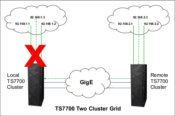
Figure 4-3 TS7700 Management Interface access from a remote cluster
IPv6 support
All network interfaces that support monitoring and management functions are now able to support IPv4 or IPv6:
•Management Interface (MI)
•Key manager server: IBM Security Key Lifecycle Manager
•Simple Network Management Protocol (SNMP) servers
•Rocket-fast System for Log processing (RSYSLOG) servers
•Lightweight Directory Access Protocol (LDAP) server
•Network Time Protocol (NTP) server
|
Important: All of these client interfaces must be either IPv4 or IPv6 for each cluster. Mixing IPv4 and IPv6 is not supported within a single cluster. For grid configurations, each cluster can be either all IPv4 or IPv6 unless an NTP server is used, in which case all clusters within the grid must be all one or the other.
Note: The TS7700 grid link interface does not support IPv6.
|
For implementation details, see “Enabling IPv6” on page 563.
IPSec support for the grid links
Use IPSec capabilities only if they are required by the nature of your business. Grid encryption might cause a considerable slowdown in all grid link traffic, such as in the following situations:
•Synchronous, immediate, or deferred copies
•Remote read or write
For more information about implementation, see “Enabling IPSec” on page 564.
TSSC Network IP addresses
The TS3000 Total Storage System Console (TSSC) uses an internal isolated network that is known as the TSSC network. All separate elements in the TS7700 tape subsystem connect to this network and are configured in the TSSC by the IBM SSR.
Each component of your TS7700 tape subsystem that is connected to the TSSC uses at least one Ethernet port in the TSSC Ethernet hub. For example, a TS7700 cluster needs two connections (one from the primary switch and other from the alternative switch). If your cluster is a TS7740, TS7720T, or TS7760T, you need a third port for the TS3500 or TS4500 tape library. Depending on the size of your environment, you might need to order a console expansion for your TSSC. For more information, see FC2704 in the IBM TS7700 R4.2 IBM Knowledge Center:
https://ibm.biz/Bd2H99
Generally, there should be at least one TSSC available per location in proximity of the tape devices, such as TS7700 clusters and TS3500 tape libraries. Apart from the internal TSSC network, the TSSC can also have another two Ethernet physical connections:
•External Network Interface
•Grid Network Interface
Those two Ethernet adapters are used by advanced functions, such as AOTM, LDAP, Assist On-site (AOS), and Call Home (not using a modem). If you plan to use them, provide one or two Ethernet connections and the corresponding IP addresses for the TSSC. The ports in the table must be opened in the firewall for the interface links to work properly. Table 4-11 lists the network port requirements for the TSSC.
Table 4-11 TSSC TCP/IP port requirement
|
TSSC interface link
|
TCP/IP port
|
Role
|
|
TSSC External
|
80
|
Call Home
|
|
|
443
|
|
|
|
53
|
Advise to remain open for the domain name server
|
|
|
Internet Control Message Protocol (ICMP)
|
|
|
TSSC Grid
|
80
|
Autonomic Ownership Takeover Mode (AOTM)
|
|
|
22
|
Secure Shell (ssh)
|
|
|
443
|
Secure HTTP (outbound broadband call home)
|
|
|
9666
|
Internal TSSC network communication protocol
|
|
|
ICMP
|
|
Network switches and TCP/IP port requirements
The network switch and TCP/IP port requirements for the WAN of a TS7700 in the grid configuration are listed in Table 4-12.
|
Clarification: These requirements apply only to the LAN/WAN infrastructure. The TS7700 internal network is managed and controlled by internal code.
|
Table 4-12 Infrastructure grid WAN TCP/IP port assignments
|
Link
|
TCP/IP port
|
Role
|
|
TS7700 MI
|
ICMP
|
Dead gateway detection
|
|
1231
|
NTP uses the User Datagram Protocol (UDP) time server
|
|
|
443
|
Access the TS7700 MI (HTTPS)
|
|
|
80
|
Access the remote MI when clusters are operating at different code levels (HTTP)
|
|
|
1443
|
Encryption Key Management (EKM)
|
|
|
3801
|
Encryption Key Management (EKM)
|
|
|
TS7700 GRID
|
ICMP
|
Check cluster health
|
|
9
|
Discard port for speed measurement between grid clusters
|
|
|
80
|
Access the remote MI when clusters are operating at different code levels
|
|
|
123a
|
NTP time server
|
|
|
1415/1416
|
IBM WebSphere® message queues
|
|
|
443
|
Access the TS7700 MI
|
|
|
350
|
TS7700 file replication, Remote Mount, and Sync Mode Copy (distributed library file transfer)
|
|
|
20
|
For use by IBM Support
|
|
|
21
|
For use by IBM support
|
|
|
500
|
IPSec Key Exchange (TCP and UDP): Must remain open when grid encryption is enabled.
|
|
|
8500
|
IPSec Key Exchange (TCP and UDP): Must remain open when grid encryption is enabled.
|
1 Port 123 is used for grid link time synchronization within clusters, not for an external time server.
4.1.4 Factors that affect performance at a distance
Fibre Channel distances depend on the following factors:
• Type of laser used: Long wavelength or short wavelength
• Type of fiber optic cable: Multi-mode or single-mode
• Quality of the cabling infrastructure in terms of decibel (dB) signal loss:
– Connectors
– Cables
– Bends and loops in the cable
•Link extenders
Native SW Fibre Channel transmitters have a maximum distance of 150 m with 50-micron diameter, multi-mode, optical fiber (at 4 Gbps). Although 62.5-micron, multimode fiber can be used, the larger core diameter has a greater dB loss and maximum distances are shortened to 55 meters. Native LW Fibre Channel transmitters have a maximum distance of 10 km (6.2 miles) when used with 9-micron diameter single-mode optical fiber. See the Table 4-13 on page 156 for a comparative table.
Link extenders provide a signal boost that can potentially extend distances to up to about
100 km (62 miles). These link extenders act as a large, fast pipe. Data transfer speeds over link extenders depend on the number of buffer credits and efficiency of buffer credit management in the Fibre Channel nodes at either end. Buffer credits are designed into the hardware for each Fibre Channel port. Fibre Channel provides flow control that protects against collisions.
100 km (62 miles). These link extenders act as a large, fast pipe. Data transfer speeds over link extenders depend on the number of buffer credits and efficiency of buffer credit management in the Fibre Channel nodes at either end. Buffer credits are designed into the hardware for each Fibre Channel port. Fibre Channel provides flow control that protects against collisions.
This configuration is important for storage devices, which do not handle dropped or out-of-sequence records. When two Fibre Channel ports begin a conversation, they exchange information about their number of supported buffer credits. A Fibre Channel port sends only the number of buffer frames for which the receiving port has given credit.
This approach both avoids overruns and provides a way to maintain performance over distance by filling the pipe with in-flight frames or buffers. The maximum distance that can be achieved at full performance depends on the capabilities of the Fibre Channel node that is attached at either end of the link extenders.
This relationship is vendor-specific. There must be a match between the buffer credit capability of the nodes at either end of the extenders. A host bus adapter (HBA) with a buffer credit of 64 communicating with a switch port with only eight buffer credits is able to read at full performance over a greater distance than it is able to write because, on the writes, the HBA can send a maximum of only eight buffers to the switch port.
On the reads, the switch can send up to 64 buffers to the HBA. Until recently, a rule has been to allocate one buffer credit for every 2 km (1.24 miles) to maintain full performance.
Buffer credits within the switches and directors have a large part to play in the distance equation. The buffer credits in the sending and receiving nodes heavily influence the throughput that is attained in the Fibre Channel. Fibre Channel architecture is based on a flow control that ensures a constant stream of data to fill the available pipe. Generally, to maintain acceptable performance, one buffer credit is required for every 2 km (1.24 miles) distance that is covered. For more information, see IBM SAN Survival Guide, SG24-6143.
4.1.5 Host attachments
The TS7700 attaches to IBM Z hosts through the FICON adapters on the host, either FICON LW or SW, at speeds of 4, 8, or 16 Gbps. 1 and 2 Gbps connection speeds are no longer supported by the newest 16 Gb FICON Adapters:
•ESCON channel attachment is not supported.
•FICON channel extension and DWDM connection are supported.
•FICON directors and director cascading are supported.
|
Note: Considerations for host FICON connections:
•IBM Z systems using 8 Gbps FICON ports do support only TS7700 connections running 4 Gbps and 8 Gbps speeds for direct attachments. However, 2 Gbps connections to TS7700 are also supported if FICON Director provides proper speed conversion.
•IBM Z 16 Gbps FICON supports only TS7700 16 Gbps and 8 Gbps FICON direct-attached.
•IBM Z 16 Gbps FICON supports TS7700 4 Gbps FICON if FICON Director provides proper speed conversion.
|
Host attachment supported distances
When directly attaching to the host, the TS7700 can be installed at a distance of up to 10 km (6.2 miles) from the host. With FICON switches, also called FICON Directors or Dense Wave Division Multiplexers (DWDMs), the TS7700 can be installed at extended distances from the host.
Figure 4-4 shows a sample diagram that includes the DWDM and FICON Directors specifications. For more information, see “FICON Director support” on page 156.

Figure 4-4 The IBM Z host attachment to the TS7700 (at speed of 8 Gbps)
The maximum distances vary depending on the cable type and on the speed and type of optical transducer. There are three basic types of optical cable fiber:
•The orange colored cables are SW, multimode OM2 type cables.
•The aqua colored multimode cables are OM3, OM4 type and are laser-optimized.
•The yellow colored LW cables are single mode. The connection speed in Gbps determines the distance that is allowed.
Table 4-13 lists the relationship between connection speed and distance by cable type.
Table 4-13 Connection speed and distance by cable type
|
Cable type
|
Connection Speed
|
Maximum Distance
|
|
OM2
|
4 Gbps
|
150 m (492 ft.)
|
|
OM3
|
4 Gbps
|
270 m (886 ft.)
|
|
OM3
|
8 Gbps
|
150 m (492 ft.)
|
|
OM4
|
8 Gbps
|
190 m (623 ft.)
|
|
OM2
|
16 Gbps
|
35 m (115 ft.)
|
|
OM3
|
16 Gbps
|
100 m (328 ft.)
|
|
OM4
|
16 Gbps
|
130 m (426 ft.)
|
Figure 4-4 on page 155 shows the supported distances using different fiber cables for single-mode long wave laser and multimode short wave laser.
These attachments used the following abbreviations:
•SM: Single Mode fiber
•LW: Long Wave Laser
•MM: Multimode Fiber
•SW: Short Wave Laser
The TS7700 supports IBM Z servers by using IBM FICON at distances up to
250 km (155 miles) by using dense wavelength division multiplexing (DWDM) in combination with switches, or more extended distances by using supported channel extension products.
250 km (155 miles) by using dense wavelength division multiplexing (DWDM) in combination with switches, or more extended distances by using supported channel extension products.
Distances greater than 30 km require DWDM in combination with qualified switches or directors with adequate random access memory (RAM) buffer online cards. An adequate RAM buffer is defined as capable of reaching distances of 100 - 250 km.
|
Note: Long wave cables attach only to long wave adapters and short wave cables attach only to short wave adapters. There is no intermixing.
|
FICON Director support
All FICON Directors are supported for single and multi-cluster grid TS7700 configurations where code level 4.2 is installed with 2 Gbps, 4 Gbps, 8 Gbps, or 16 Gbps links. The components auto-negotiate to the highest speed allowed. The 16 Gbps ports cannot negotiate down to 2 Gbps links.
You cannot mix different vendors, such as Brocade (formerly McData, CNT, and InRange) and CISCO, but you can mix models of one vendor.
For more information about specific supported intermix combinations, see the System Storage Interoperation Center (SSIC):
The FICON switch support matrix is available at the following web page:
FICON channel extenders
FICON channel extenders can operate in one of the following modes:
•Frame shuttle or tunnel mode
•Emulation mode
Using the frame shuttle or tunnel mode, the extender receives and forwards FICON frames without performing any special channel or control unit (CU) emulation processing. The performance is limited to the distance between the sites and the normal round-trip delays in FICON channel programs.
Emulation mode can go unlimited distances, and it monitors the I/O activity to devices. The channel extender interfaces emulate a CU by presenting command responses and channel end (CE)/device end (DE) status ahead of the controller, and emulating the channel when running the pre-acknowledged write operations to the real remote tape device. Therefore, data is accepted early and forwarded to the remote device to maintain a full pipe throughout the write channel program.
The supported channel extenders between the IBM Z host and the TS7700 are in the same matrix as the FICON switch support at the following web page (see the FICON Channel Extenders section):
Cascaded switches
The following list summarizes the general configuration rules for configurations with cascaded switches:
•Director Switch ID
This is defined in the setup menu.
The inboard Director Switch ID is used on the SWITCH= parameter in the CHPID definition. The Director Switch ID does not have to be the same as the Director Address. Although the example uses a different ID and address for clarity, keep them the same to reduce configuration confusion and simplify problem determination work.
The following allowable Director Switch ID ranges have been established by the manufacturer:
– McDATA range: x'61' - x'7F'
– CNT/Inrange range: x'01' - x'EF'
– Brocade range: x'01' - x'EF'
•Director Address
This is defined in the Director GUI setup.
The Director Domain ID is the same as the Director Address that is used on the LINK parameter in the CNTLUNIT definition. The Director Address does not have to be the same as the Director ID, but again, keep them the same to reduce configuration confusion and simplify PD work.
The following allowable Director Address ranges have been established by the manufacturer:
– McDATA range: x'61' - x'7F'
– CNT/Inrange range: x'01' - x'EF'
– Brocade range: x'01' - x'EF'
•Director Ports
The Port Address might not be the same as the Port Number. The Port Number identifies the physical location of the port, and the Port Address is used to route packets.
The Inboard Director Port is the port to which the CPU is connected. The Outboard Director Port is the port to which the CU is connected. It is combined with the Director Address on the LINK parameter of the CNTLUNIT definition:
– Director Address (hex) combined with Port Address (hex): Two bytes
– Example: LINK=6106 indicates a Director Address of x'61' and a Port Address of x'06'
•External Director connections:
– Inter-Switch Links (ISLs) connect to E Ports.
– FICON channels connect to F Ports.
•Internal Director connections
Port type and port-to-port connections are defined by using the available setup menu in the equipment. Figure 4-5 shows an example of host connection that uses DWDM and cascaded switches.

Figure 4-5 Host connectivity that uses DWDM and cascaded switches
4.1.6 Planning for LDAP for user authentication in your TS7700 subsystem
Depending on the security requirements in place, the user of the TS7700 can choose to
have all of the TS7700 users’ authentications controlled and authorized centrally by an LDAP server.
have all of the TS7700 users’ authentications controlled and authorized centrally by an LDAP server.
|
Important: Enabling LDAP requires that all users must authenticate with the LDAP server. All interfaces to the TS7700, such as MI, remote connections, and even the local serial port, are blocked. The TS7700 might be inaccessible if the LDAP server is unreachable.
|
The previous implementation relied on System Storage Productivity Center to authenticate users to a client’s LDAP server. Beginning with Release 3.0 of LIC, both the TS7700 clusters and the TSSC have native support for the LDAP server (currently, only Microsoft Active Directory (MSAD) is supported). System Storage Productivity Center continues to be a valid approach for LDAP.
Enabling authentication through an LDAP server means that all personnel with access to the TS7700 subsystem, such as computer operators, storage administrators, system programmers, and IBM SSRs (local or remote), must have a valid account in the LDAP server, along with the roles assigned to each user. The role-based access control (RBAC) is also supported. If the LDAP server is down or unreachable, it can render a TS7700 inaccessible from the outside.
|
Important: Create at least one external authentication policy for IBM SSRs before a service event.
|
When LDAP is enabled, the TS7700 MI is controlled by the LDAP server. Record the
Direct LDAP policy name, user name, and password that you created for IBM SSRs and keep this information easily available in case you need it. Service access requires the IBM SSR to authenticate through the normal service login and then to authenticate again by using the IBM SSR Direct LDAP policy.
Direct LDAP policy name, user name, and password that you created for IBM SSRs and keep this information easily available in case you need it. Service access requires the IBM SSR to authenticate through the normal service login and then to authenticate again by using the IBM SSR Direct LDAP policy.
For more information about how to configure LDAP availability, see “Defining security settings” on page 564.
4.1.7 Cluster time coordination
All nodes in the entire subsystem must coordinate their time with one another. All nodes in the system keep track of time in relation to Coordinated Universal Time (UTC), also known as Greenwich Mean Time (GMT). Statistics are also reported in relation to UTC.
External NTP is required when any of the grid members are configured to use the Cloud Storage Tier because Time Synchronization is demanded for the cloud TS7760C interaction.
Figure 4-6 shows the NTP server configuration in grid.

Figure 4-6 NTP server configuration
The NTP server address is configured into system VPD on a system-wide scope, so that all clusters access the same NTP server. All of the clusters in a grid need to be able to communicate with the same NTP server that is defined in VPD. In the absence of an NTP server, all nodes coordinate time with Cluster 0 (or the lowest-numbered available cluster in the grid).
4.2 Planning for a grid operation
The TS7700 grid provides configuration flexibility to meet various requirements. Those requirements depend on both your business and your applications. This section specifically addresses planning a two-cluster grid configuration to meet HA needs. However, the configuration easily converts to a three-cluster grid configuration with two production clusters of HA and disaster recovery (DR). The third cluster is strictly a DR site.
4.2.1 Autonomic Ownership Takeover Manager considerations
The Autonomic Ownership Takeover Manager (AOTM) is an optional function which, following a TS7700 cluster failure, will automatically enable one of the methods for ownership takeover without operator intervention, improving the availability of the TS7700. It uses the TS3000 System Console associated with each TS7700 to provide an alternate path to check the status of a peer TS7700.
Without AOTM, an operator must determine if one of the TS7700 clusters has failed, and then enable one of the ownership takeover modes. This is required to access the virtual volumes that are owned by the failed cluster. It is very important that write ownership takeover be enabled only when a cluster has failed, and not when there is a problem only with communication between the TS7700 clusters.
If it is enabled and the cluster in question continues to operate, data might be modified independently on other clusters, resulting in a corruption of the data. Although there is no data corruption issue with the read ownership takeover mode, it is possible that the remaining clusters might not have the latest version of the virtual volume and present previous data.
Even if AOTM is not enabled, it is advised that it be configured. Doing so provides protection from a manual takeover mode being selected when the other cluster is still functional.
With AOTM, one of the takeover modes is enabled if normal communication between the clusters is disrupted and the cluster to perform takeover can verify that the other cluster has failed or is otherwise not operating. If a TS7700 suspects that the cluster that owns a volume it needs has failed, it asks the TS3000 System Console to which it is attached to query the System Console attached to the suspected failed cluster.
If the remote system console can validate that its TS7700 has failed, it replies back and the requesting TS7700 enters the default ownership takeover mode. If it cannot validate the failure, or if the system consoles cannot communicate, an ownership takeover mode can only be enabled by an operator.
To take advantage of AOTM, the customer should provide IP communication paths between the TS3000 System Consoles at the cluster sites. For AOTM to function properly, it should not share the same paths as the Grid interconnection between the TS7700s.
|
Note: When the TSSC code level is Version 5.3.7 or higher, the AOTM and Call Home IP addresses can be on the same subnet. However, earlier levels of TSSC code require the AOTM and Call Home IP addresses to be on different subnets. It is advised to use different subnets for those interfaces.
|
AOTM can be enabled through the MI interface, and it is also possible to set the default ownership takeover mode.
4.2.2 Defining grid copy mode control
When upgrading a stand-alone cluster to a grid, FC4015, Grid Enablement must be installed on all clusters in the grid. Also, you must set up the Copy Consistency Points in the Management Class (MC) definitions on all clusters in the new grid. The data consistency point is defined in the MC’s construct definition through the MI. You can perform this task only for an existing grid system.
In a stand-alone cluster configuration, you can choose between three consistency points per cluster:
•No Copy (NC): No copy is made to this cluster.
•Rewind Unload (RUN): A valid version of the virtual volume has been copied to this cluster as part of the volume unload processing.
•Deferred (DEF): A replication of the modified virtual volume is made to this cluster after the volume had been unloaded.
•Synchronous Copy: Provides tape copy capabilities up to synchronous-level granularity across two clusters within a multi-cluster grid configuration. For more information, see “Synchronous mode copy” on page 86.
•Time Delayed: Introduced in Release 3.1, this policy enables better control of what data needs to be replicated to other existing clusters in the grid. For example, if a large portion of the data that is written to tape expires quickly in your environment, Time Delayed replication makes it possible to delay the copies to a remote Tape-attached cluster for later than the average Lifecycle of your data.
• Then, most of the data expires before the time set for the delayed copies runs out, avoiding the processor burden introduced by the replication of archive or short retention data, and later the additional reclamation activity on the Tape-attached cluster. Time delay can be set from 1 hour to 65,535 hours.
For more information, see the following web pages:
•IBM TS7700 Series Best Practices - TS7700 Hybrid Grid Usage
•IBM TS7700 Series Best Practices - Copy Consistency Points
•IBM TS7700 Series Best Practices - Synchronous Mode Copy
Define Copy Policy Override settings
With the TS7700, you can define and set the optional override settings that influence the selection of the I/O Tape Volume Cache (TVC) and replication responses. The settings are specific to each cluster in a multi-cluster grid configuration, which means that each cluster can have different settings, tailored to meet your requirements. The settings take effect for any mount requests received after you save the changes. Mounts already in progress are not affected by a change in the settings.
You can define and set the following settings:
•Prefer local cache for Fast Ready mount requests
A scratch (Fast Ready) mount selects a local copy if a cluster Copy Consistency Point is not specified as No Copy in the MC for the mount. The cluster is not required to have a valid copy of the data.
•Prefer local cache for private (non-Fast Ready) mount requests
This override causes the local cluster to satisfy the mount request if the cluster is available and the cluster has a valid copy of the data, even if that data is only resident on physical tape. If the local cluster does not have a valid copy of the data, the default cluster selection criteria applies.
|
Important: The Synchronous mode copy feature takes precedence over any Copy Override settings.
|
•Force volumes that are mounted on this cluster to be copied to the local cache
For a private (non-Fast Ready) mount, this override causes a copy to be created on the local cluster as part of mount processing. For a scratch (Fast Ready) mount, this setting overrides the specified MC with a Copy Consistency Point of Rewind-Unload for the cluster. This does not change the definition of the MC, but serves to influence the Replication policy.
•Enable fewer RUN consistent copies before reporting RUN command complete
If selected, the value that is entered for Number of required RUN consistent copies, including the source copy, is used to determine the number of copies to override before the RUN operation reports as complete. If this option is not selected, the MC definitions are used explicitly. Therefore, the number of RUN copies can be from one to the number of clusters in the grid.
•Ignore cache preference groups for copy priority
If this option is selected, copy operations ignore the cache preference group when determining the priority of volumes that are copied to other clusters.
|
Consideration: In a Geographically Dispersed Parallel Sysplex (GDPS), all three Copy Policy Override settings (cluster overrides for certain I/O and copy operations) must be selected on each cluster to ensure that wherever the GDPS primary site is, this TS7700 cluster is preferred for all I/O operations. If the TS7700 cluster of the GDPS primary site fails, you must complete the following recovery actions:
1. Vary on virtual devices from a remote TS7700 cluster from the primary site of the GDPS host.
2. Manually start, through the TS7700 MI, a read/write Ownership Takeover (WOT), unless AOTM already has transferred ownership.
|
4.2.3 Defining scratch mount candidates
Scratch allocation assistance (SAA) is an extension of the device allocation assistance (DAA) function for scratch mount requests. SAA filters the list of clusters in a grid to return to the host a smaller list of candidate clusters that are designated as scratch mount candidates.
If you have a grid with two or more clusters, you can define scratch mount candidates. For example, in a hybrid configuration, the scratch allocation assist (SAA) function can be used to direct certain scratch allocations (workloads) to one or more TS7700Ds or cache partition (CP0) of a TS7700Ts for fast access, while other workloads can be directed to TS7740s or the cache partition (CPx) of TS7760Ts for archival purposes.
Clusters not included in the list of scratch mount candidates are not used for scratch mounts at the associated MC unless those clusters are the only clusters that are known to be available and configured to the host. If you have enabled SAA, but not selected any cluster as SAA candidates in the Management Class, all clusters are treated as SAA candidates.
Understand that SAA only influences the mount behavior of the grid. Although other clusters can be selected as mount point if the original SAA clusters are not available or not configured to the host, they will not be considered for the TVC selection. If all clusters specified in the Management Class as target are not available, the mount might be processed, but the job will hang afterwards.
Before SAA is operational, the SAA function must be enabled in the grid by using the LI REQ SETTING SCRATCH ENABLE command.
4.2.4 Retain Copy mode
Retain Copy mode is an optional attribute, controlled by Management Class construct configuration, where a volume’s previously existing Copy Consistency Points are accepted rather than applying the Copy Consistency Points defined at the mounting cluster. This applies to private volume mounts for reads or write appends. It is used to prevent more copies of a volume from being created in the grid than wanted. This is important in a grid with three or more clusters that has two or more clusters online to a host.
4.2.5 Defining cluster families
If you have a grid with three or more clusters, you can define cluster families.
This function introduces a concept of grouping clusters together into families. Using cluster families, you can define a common purpose or role to a subset of clusters within a grid configuration. The role that is assigned, for example, production or archive, is used by the TS7700 Licensed Internal Code to make improved decisions for tasks, such as replication and TVC selection. For example, clusters in a common family are favored for TVC selection, or replication can source volumes from other clusters within its family before using clusters outside of its family.
4.2.6 TS7720 and TS7760 cache thresholds and removal policies
These thresholds determine the state of the cache as it relates to remaining free space.
Cache thresholds for a TS7720 or TS7760 cluster
There are three thresholds that define the capacity of CP0 in a TS7720T or TS7760T and the active cache capacity in a TS7720D or TS7760D. These thresholds determine the state of the cache as it relates to remaining free space.
The following list describes the three thresholds in ascending order of occurrence:
•Automatic Removal
The policy removes the oldest logical volumes from the TS7720 or TS7760 cache if a consistent copy exists elsewhere in the grid. This state occurs when the cache is 3 TB below the out-of-cache-resources threshold. In the automatic removal state, the TS7720 or TS7760 automatically removes volumes from the disk-only cache to prevent the cache from reaching its maximum capacity.
This state is identical to the limited-free-cache-space-warning state unless the Temporary Removal Threshold is enabled. You can also lower the removal threshold in the LI REQ. The default is 4 TB.
To perform removal operations in a TS7720T or TS7760T, the size of CP0 must be at least 10 TB:
– You can disable automatic removal within any specific TS7720 cluster by using the following LIBRARY REQUEST command:
LIBRARY REQUEST,library-name,CACHE,REMOVE,{ENABLE|DISABLE}
– The default automatic removal threshold can be changed from the command line by using the following library request command:
LIBRARY REQUEST,library-name,CACHE,REMVTHR,{VALUE}
Automatic removal is temporarily disabled while disaster recovery write protect is enabled on a disk-only cluster so that a DR test can access all production host-written volumes. When the write protect state is lifted, automatic removal returns to normal operation.
•Limited free cache space warning
This state occurs when there is less than 3 TB of free space that is left in the cache. After the cache passes this threshold and enters the limited-free-cache-space-warning state, write operations can use only an extra 2 TB before the out-of-cache-resources state is encountered. When a TS7720 or TS7760 enters the limited-free-cache-space-warning state, it remains in this state until the amount of free space in the cache exceeds 3.5 TB.
The following messages can be displayed on the MI during the limited-free-cache-space-warning state:
– HYDME0996W
– HYDME1200W
For more information about these messages, see TS7700 IBM Knowledge Center:
https://ibm.biz/Bd2HCd
|
Clarification: Host writes to the TS7720 or TS7760 and inbound copies continue during this state.
|
•Out of cache resources
This state occurs when there is less than 1 TB of free space that is left in the cache. After the cache passes this threshold and enters the out-of-cache-resources state, it remains in this state until the amount of free space in the cache exceeds 3.5 TB. When a TS7720 or TS7760 is in the out-of-cache-resources state, volumes on that cluster become read-only and one or more out-of-cache-resources messages are displayed on the MI. The following messages can display:
– HYDME0997W
– HYDME1133W
– HYDME1201W
For more information about these messages, see TS7700 IBM Knowledge Center:
https://ibm.biz/Bd2HCd
|
Clarification: Although host allocations are not aware of a TS7720 or TS7760 in the out of cache resource state, the TS7700 grid avoids using a TS7720 or TS7760 in this state as a valid TVC candidate. New host allocations sent to a TS7720 or TS7760 in this state choose a remote TVC instead.
If all valid clusters are in this state or unable to accept mounts, the host allocations fail. Read mounts can choose the TS7720 or TS7760 in this state, but modify and write operations fail. Copies inbound to this TS7720 or TS7760 are queued as Deferred until the TS7720 or TS7760 exits this state.
|
Table 4-14 lists the start and stop thresholds for each of the active cache capacity states that are defined.
Table 4-14 Active cache capacity state thresholds
|
State
|
Enter state (free space available)
|
Exit state (free space available)
|
Host message displayed
|
|
Automatic removal
|
< 4 TB
|
> 4.5 TB
|
CBR3750I when automatic removal begins
|
|
Limited free cache space warning (CP0 for a TS7720T)
|
< 3 TB
|
> 3.5 TB or 15% of the size of CP0, whichever is less
|
CBR3792E upon entering state
CBR3793I upon exiting state
|
|
Out of cache resources (CP0 for a TS7720T)
|
< 1 TB
|
> 3.5 TB or 5% of the size of CP0, whichever is less
|
CBR3794A upon entering state
CBR3795I upon exiting state
|
|
Temporary removal1
|
< (X = 1 TB)2
|
> (X + 1.5 TB)b
|
Console message
|
1 When enabled
2 Where X is the value set by the TVC window on the specific cluster
Volume removal policies in a grid configuration
Removal policies determine when virtual volumes are removed from the cache of a TS7720 or TS7760 cluster in a grid configuration. These policies provide more control over the removal of content from a TS7720 or TS7760 cache as the active data reaches full capacity. To perform removal operations in a TS7720T or TS7760T cluster, the size of CP0 must be at least 10 TB.
To ensure that data is always in a TS7720 or TS7760, or is in for at least a minimal amount of time, a volume copy retention time must be associated with each removal policy. This volume retention time in hours enables volumes to remain in a TS7720 or TS7760 TVC for at least x hours before it becomes a candidate for removal, where x is 0 - 65,536. A volume retention time of zero assumes no minimal requirement.
In addition to pin time, three policies are available for each volume within a TS7720D or TS7760D and for CP0 within a TS7720T or TS7760T. For more information, see Chapter 2, “Architecture, components, and functional characteristics” on page 15.
Removal threshold
The default, or permanent, removal threshold is used to prevent a cache overrun condition in a TS7720 or TS7760 cluster that is configured as part of a grid. By default, it is a 4 TB (3 TB fixed plus 1 TB) value that, when taken with the amount of used cache, defines the upper size limit for a TS7720 or TS7760 cache, or for a TS7720T or TS7760T CP0.
Above this threshold, virtual volumes are removed from a TS7720 or TS7760 cache.
|
Note: Virtual volumes are only removed if there is another consistent copy within the grid.
|
Virtual volumes are removed from a TS7720 or TS7760 cache in this order:
1. Volumes in scratch categories.
2. Private volumes that are least recently used by using the enhanced removal policy definitions.
After removal begins, the TS7720 or TS7760 continues to remove virtual volumes until the stop threshold is met. The stop threshold is a value that is the removal threshold minus
500 GB.
500 GB.
A particular virtual volume cannot be removed from a TS7720 or TS7760 cache until the TS7720 or TS7760 verifies that a consistent copy exists on a peer cluster. If a peer cluster is not available, or a volume copy has not yet completed, the virtual volume is not a candidate for removal until the appropriate number of copies can be verified later. Time delayed replication can alter the removal behavior.
|
Tip: This field is only visible if the selected cluster is a TS7720 or TS7760 in a grid configuration.
|
Temporary removal threshold
The temporary removal threshold lowers the default removal threshold to a value lower than the stop threshold in anticipation of a service mode event, or before a DR test where FlashCopy for DR testing is used.
Virtual volumes might need to be removed before one or more clusters enter service mode. When a cluster in the grid enters service mode, remaining clusters can lose their ability to make or validate volume copies, preventing the removal of enough logical volumes. This scenario can quickly lead to the TS7720 or TS7760 cache reaching its maximum capacity.
The lower threshold creates more free cache space, which enables the TS7720 or TS7760 to accept any host requests or copies during the service outage without reaching its maximum cache capacity.
The temporary removal threshold value must be greater than or equal to (>=) the expected amount of compressed host workload that is written, copied, or both to the TS7720 or TS7760 during the service outage. The default temporary removal threshold is 4 TB, which provides 5 TB (4 TB plus 1 TB) of existing free space. You can lower the threshold to any value from 2 TB to full capacity minus 2 TB.
All TS7720 or TS7760 clusters in the grid that remain available automatically lower their removal thresholds to the temporary removal threshold value that is defined for each one. Each TS7720 or TS7760 cluster can use a different temporary removal threshold. The default temporary removal threshold value is 4 TB or 1 TB more data than the default removal threshold of 3 TB. Each TS7720 or TS7760 cluster uses its defined value until the originating cluster in the grid enters service mode or the temporary removal process is canceled. The cluster that is initiating the temporary removal process does not lower its own removal threshold during this process.
4.2.7 Data management settings (TS7740/TS7700T CPx in a multi-cluster grid)
The following settings for the TS7700 are optional, and they can be configured during the installation of the TS7700, or later through the TS7700 LIBRARY REQUEST (LI REQ) command interface:
•Copies to Follow Storage Class Preference (COPYFSC)
•Recalls Preferred to be Removed from Cache (RECLPG0)
|
Note: A detailed description of the Host Console Request functions and their responses is available in IBM Virtualization Engine TS7700 Series z/OS Host Command Line Request User’s Guide, which is available at the Techdocs website:
|
Copies to follow Storage Class Preference (COPYFSC)
Normally, the TVCs in both TS7700 tape drives in a multi-cluster grid are managed as one TVC to increase the likelihood that a needed volume is in cache. By default, the volume on the TS7700 that is selected for I/O operations is preferred to stay in cache on that TS7700. The copy that is made on the other TS7700 is preferred to be removed from cache as soon as a copy to physical media is completed (through the premigrate/migrate process):
•Preferred to stay in cache means that when space is needed for new volumes, the oldest volumes are removed first. This algorithm is called the least recently used (LRU) algorithm. This is also referred to as Preference Group 1 (PG1).
•Preferred to be removed from cache means that when space is needed for new volumes, the largest volumes are removed first, regardless of when they were written to the cache. This is also referred to as Preference Group 0 (PG0).
Applied Cache Preference Group (PG0/PG1) to be applied is actually dependent on the Storage Class construct associated to individual virtual volumes. Therefore, it is possible to use different Cache Preference settings for different virtual volumes.
|
Note: Construct names are assigned to virtual volumes by the attached Host System, and they are used to establish Data Management policies to be executed by the TS7700 against specific volumes. Constructs (and associated policies) are defined in advance using the TS7700 MI. For more information, see “Defining TS7700 constructs” on page 558. If the Host System assigns a construct name without first defining it, the TS7700 will create the construct with the default parameters.
|
In the default Storage Class Case, for a TS7700 running in a dual production multi-cluster grid configuration, virtual tape drives in both TS7700 are selected as the I/O TVCs, and have the original volumes (newly created or modified) preferred in cache. The copies to the other TS7700 are preferred to be removed from cache. Therefore, each TS7700 TVC is filled with unique, newly created, or modified volumes, roughly doubling the amount of cache seen by the host.
However, for a TS7700 running in a multi-cluster grid configuration that is used for business continuance, particularly when all I/O is preferred to the local TVC, this default management method might not be wanted. If the remote site of the multi-cluster grid is used for recovery, the recovery time is minimized by having most of the needed volumes already in cache. What is needed is to have the most recent copy volumes remain in the cache, not being preferred out of cache.
Based on business requirements, this behavior can be modified for a TS7700 using the COPYFSC control:
LI REQ, <distributed-library>, SETTING, CACHE, COPYFSC, <ENABLE/DISABLE>
This control features the following characteristics:
•The default is set to disabled.
•When disabled, virtual volumes copied into the cache from a peer TS7700 are managed as PG0 volumes (prefer largest files out of cache first), regardless of local definition of the associated Storage Class construct.
•When set to enabled, virtual volumes copied into the cache from a peer TS7700 are managed using the actions defined for the Storage Class construct associated with the volume, as locally defined.
Recalls preferred for cache removal (RECLPG0)
Normally, a volume recalled into cache is managed as though it were newly created or modified because it is in the TS7700 that is selected for I/O operations on the volume. A recalled volume displaces other volumes in cache.
If the remote TS7700 is used for recovery, the recovery time is minimized by having most of the needed volumes in cache. However, it is not likely that all of the volumes to restore will be resident in the cache, so some number of recalls is required. Unless you can explicitly control the sequence of volumes to be restored, it is likely that recalled volumes will displace cached volumes that have not yet been restored from, resulting in further recalls later in the recovery process.
After a restore completes from a recalled volume, that volume is no longer needed. These volumes must be removed from the cache after they have been accessed so that they minimally displace other volumes in the cache.
Based on business requirements, this behavior can be modified using the RECLPG0 setting:
LI REQ, <distributed-library>, SETTING, CACHE, RECLPG0, <ENABLE/DISABLE>
This setting has these characteristics:
•When disabled, which is the default, virtual volumes that are recalled into cache are managed using the actions defined for the Storage Class construct associated with the volume as defined in the local TS7700.
•When enabled, recalls are managed as PG0 volumes (prefer out of cache first by largest size), regardless of local definition of the associated Storage Class construct.
4.2.8 High availability considerations
High availability means being able to provide continuous access to virtual volumes through planned and unplanned outages with as little user effect or intervention as possible. It does not mean that all potential for user effect or action is eliminated. The following guidelines relate to establishing a grid configuration for HA:
•The production systems, which are the sysplexes and logical partitions (LPARs), have FICON channel connectivity to both clusters in the grid. The IBM Data Facility Storage Management Subsystem (DFSMS) library definitions and input/output definition file (IODF) have been established, and the appropriate FICON Directors, DWDM attachments, and fiber are in place.
Virtual tape devices in both clusters in the grid configuration are varied online to the production systems. If virtual tape device addresses are not normally varied on to both clusters, the virtual tape devices to the standby cluster need to be varied on in a planned or unplanned outage to enable production to continue.
•For the workload placed on the grid configuration, when using only one of the clusters, performance throughput needs to be sufficient to meet service level agreements (SLAs). Assume that both clusters are normally used by the production systems (the virtual devices in both clusters are varied online to production). In the case where one of the clusters is unavailable, the available performance capacity of the grid configuration can be reduced by up to one half.
•For all data that is critical for high availability, consider using an MC whose Copy Consistency Point definition has both clusters with a Copy Consistency Point of RUN (immediate copy) or SYNC (sync mode copy). Therefore, each cluster has a copy of the data when the following conditions occur:
– The volume is closed and unloaded from the source cluster for immediate copy.
– Both clusters have copies that are written at the same time with Synchronous mode copy.
•The following types of applications can benefit from Synchronous mode copy (SMC):
– DFSMS Hierarchical Storage Manager (DFSMShsm).
– DFSMS Data Facility Product (DFSMSdfp) OAM Object Support.
– Other applications that use data set-style stacking.
– Any host application that requires zero recovery point objective (RPO) at sync point granularity.
The copy is updated at the same time as the original volume, keeping both instances of this logical volume synchronized at the record level. See Chapter 2, “Architecture, components, and functional characteristics” on page 15 for a detailed description.
•The distance of grid links between the clusters might influence the grid link performance. Job execution times that use Synchronous or Immediate mode might be affected by this factor. Low-latency directors, switches, or DWDMs might help to optimize the network performance. Avoid network quality of service (QoS) or other network sharing methods because they can introduce packet loss, which directly reduces the effective replication bandwidth between the clusters.
•To improve performance and take advantage of cached versions of logical volumes, do not configure the Prefer Local Cluster for private mounts and Force Local Copy Override settings in either cluster. This setting is suggested for homogeneous TS7720D or TS7760D grids. See 11.21, “Virtual Device Allocation in z/OS with JES2” on page 731.
•To minimize operator actions when a failure has occurred in one of the clusters, which makes it unavailable, set up the AOTM to automatically place the remaining cluster in at least the Read Ownership Takeover (ROT) mode. Use read/WOT mode if you want to modify existing tapes, or if you think that your scratch pool might not be large enough without using those scratch volumes that are owned by the downed cluster.
If AOTM is not used, or it cannot positively determine whether a cluster has failed, an operator must determine whether a cluster has failed and, through the MI on the remaining cluster, manually select one of the ownership takeover modes.
•If multiple grid configurations are available for use by the same production systems, you can optionally remove the grid that experienced an outage from the Storage Group (SG) for scratch allocations. This directs all scratch allocations to fully functional grids while still enabling reads to access the degraded grid. This approach might be used if the degraded grid cannot fully complete the required replication requirements. Use this approach only for read access.
By following these guidelines, the TS7700 grid configuration supports the availability and performance goals of your workloads by minimizing the effect of the following outages:
•Planned outages in a grid configuration, such as Licensed Internal Code or hardware updates to a cluster. While one cluster is being serviced, production work continues with the other cluster in the grid configuration after virtual tape device addresses are online to the cluster.
•Unplanned outage of a cluster. For the logical volumes with an Immediate or Synchronous Copy policy effective, all jobs that completed before the outage have a copy of their data available on the other cluster. For jobs that were in progress on the cluster that failed, they can be reissued after virtual tape device addresses are online on the other cluster (if they were not already online) and an ownership takeover mode has been established (either manually or through AOTM).
If it is necessary, access existing data to complete the job. For more details about AOTM, see 2.3.34, “Autonomic Ownership Takeover Manager” on page 96. For jobs that were writing data, the written data is not accessible and the job must start again.
|
Important: Scratch categories and Data Classes (DCs) settings are defined at the system level. Therefore, if you modify them in one cluster, it applies to all clusters in that grid.
|
4.2.9 Planning for cloud operation
The following tasks must be performed from the cloud administration side:
•Choose the cloud provider and obtain its URL so it can be associated to a cluster in the grid to perform the premigrate tasks to cloud.
•Obtain the access credentials to configure TS7700 cloud accounts.
•Determine the cloud space to serve as cloud containers for the TS7700.
The following tasks must be performed from the TS7760C management interface:
•Define the cloud pool
•Define the non-resident cache partition
4.3 Planning for software implementation
This section provides information for planning tasks that are related to host configuration and software requirements for use with the TS7700.
4.3.1 Host configuration definition
Library names, Library IDs, and port IDs are used to define the TS7700 to the host at the hardware, operating system, and SMS levels. Some of these identifiers are also used by the IBM SSR in the hardware configuration phase of installation.
On the host side, definitions must be made in HCD and in the SMS. For an example, see Table 4-15, and create a similar one during your planning phase. It is used in later steps. The Library ID must contain only hexadecimal characters (0 - 9 and A - F).
Table 4-15 Sample of library names and IDs in a four-cluster grid implementation
|
TS7700 virtual library names
|
SMS name1
|
LIBRARY-ID
|
Defined in HCD
|
Defined in SMS
|
|
IBMC1 (Composite)
|
IBMC1
|
C7401
|
Yes
|
Yes
|
|
IBMD1TU (Distributed Tucson)
|
IBMD1TU
|
D1312
|
No
|
Yes
|
|
IBMD1PH (Distributed Phoenix)
|
IBMD1PH
|
D1307
|
No
|
Yes
|
|
IBMD1SJ (Distributed San Jose)
|
IBMD1SJ
|
D1300
|
No
|
Yes
|
|
IBMD1AT (Distributed Atlanta)
|
IBMD1AT
|
D1963
|
No
|
Yes
|
1 The SMS name cannot start with a “V”.
Distributed library name and composite library name
The distributed library name and the composite library name are defined to z/OS and DFSMS. The composite library name is linked to the composite library ID when defining the tape library to DFSMS, as shown in Figure 6-6 on page 242. In the same manner, the distributed library name is linked to the distributed library ID, as shown in Figure 6-9 on page 243. Use names that are similar to those listed in Table 4-15.
Use the letter “C” to indicate the composite library names and the letter “D” to indicate the distributed library names. The composite library name and the distributed library name cannot start with the letter “V”.
The distributed library name and the composite library name are not directly tied to the configuration parameters that are used by the IBM SSR during the installation of the TS7700. These names are not defined to the TS7700 hardware. However, to make administration easier, associate the LIBRARY-IDs with the SMS library names through the nickname setting in the TS7700 MI.
|
Remember: Match the distributed and composite library names that are entered at the host with the nicknames that are defined at the TS7700 MI. Although they do not have to be the same, this guideline simplifies the management of the subsystem.
|
LIBRARY-ID and LIBPORT-ID
LIBRARY-ID and LIBPORT-ID are z/OS HCD parameters that enable HCD to provide the composite library configuration information that is normally obtained by the operating system at IPL time. If the devices are unavailable during IPL, the HCD information enables the logical tape devices to be varied online (when they later become available to the system) without reactivating the IODF.
|
Tip: Specify the LIBRARY-ID and LIBPORT-ID in your HCD/IOCP definitions, even in a stand-alone configuration. This configuration reduces the likelihood of having to reactivate the IODF when the library is not available at IPL, and provides enhanced error recovery in certain cases. It might also eliminate the need to have an IPL when you change your I/O configuration. In a multicluster configuration, LIBRARY-ID and LIBPORT-ID must be specified in HCD, as shown in Table 4-15.
|
Distributed library ID
During installation planning, each cluster is assigned a unique, five-digit hexadecimal number (that is, the sequence number). This number is used during subsystem installation procedures by the IBM SSR. This is the distributed library ID. This sequence number is arbitrary, and can be selected by you. It can start with the letter D.
In addition to the letter D, you can use the last four digits of the hardware serial number if it consists only of hexadecimal characters. For each distributed library ID, it is the last four digits of the TS7700 serial number.
If you are installing a new multi-cluster grid configuration, you might consider choosing LIBRARY-IDs that clearly identify the cluster and the grid. The following examples can be the distributed library IDs of a four-cluster grid configuration:
Cluster 0 DA01A
Cluster 1 DA01B
Cluster 2 DA01C
Cluster 3 DA01D
The composite library ID for this four-cluster grid can then be CA010.
|
Important: Whether you are using your own or IBM nomenclature, the important point is that the subsystem identification must be clear. Because the identifier that appears in all system messages is the SMS library name, it is important to distinguish the source of the message through the SMS library name.
The distributed library ID is not used in defining the configuration in HCD.
|
Composite library ID
The composite library ID is defined during installation planning and is arbitrary. The LIBRARY-ID is entered by the IBM SSR into the TS7700 configuration during hardware installation. All TS7700 tape drives participating in a grid have the same composite library ID. In the example in “Distributed library ID”, the composite library ID starts with a “C” for this five hex-character sequence number.
The last four characters can be used to identify uniquely each composite library in a meaningful way. The sequence number must match the LIBRARY-ID that is used in the HCD library definitions and the LIBRARY-ID that is listed in the Interactive Storage Management Facility (ISMF) Tape Library definition windows.
|
Remember: In all configurations, each LIBRARY-ID, whether distributed or composite, must be unique.
|
LIBPORT-ID
Each logical control unit (LCU), or 16-device group, must present a unique subsystem identification to the IBM Z host. This ID is a 1-byte field that uniquely identifies each LCU within the cluster, and is called the LIBPORT-ID. The value of this ID cannot be 0.
Table 4-16 on page 174 lists the definitions of the LIBPORT-IDs in a multi-cluster grid. For Cluster 0, 256 devices is 01 - 10 and 496 devices is 01 - 1F. LIBPORT-ID is always one more than CUADD.
Table 4-16 Subsystem identification definitions
|
Cluster
|
Logical CU (hex)
|
LIBPORT-ID (hex)
|
|
0
|
0 - 1E
|
X’01’-X’1F’
|
|
1
|
0 - 1E
|
X’41’-X’5F’
|
|
2
|
0 - 1E
|
X’81’-X’9F’
|
|
3
|
0 - 1E
|
X’C1’-X’DF’
|
|
4
|
0 - 1E
|
X’21’-X’3F’
|
|
5
|
0 - 1E
|
X’61’-X’7F’
|
|
6
|
0 - 1E
|
X’A1’-X’BF’
|
|
7
|
0 - 1E
|
X’E1’-X’FF’
|
Virtual tape drives
The TS7700 presents a tape drive image of a 3490 C2A, identical to the IBM Virtual Tape Server (VTS) and peer-to-peer (PTP) subsystems. Command sets, responses to inquiries, and accepted parameters match the defined functional specifications of a 3490E drive. Depending on the machine model and installed features, this collection can contain up to 31 LCUs and 496 virtual drives. Virtual drives are organized in groups of 16 drive addresses under a single LCU address.
4.3.2 Software requirements
The TS7700 is supported at z/OS V2R2 or later (earlier release level support must be done through the RPQ process). For more information about the support that is provided for the specified releases of the TS7700, see the following APARs:
•APAR OA37267 for Release 2.1.
•No other host software support is provided for Release 3.0.
•APAR OA40572 for Release 3.1.
•APAR OA44351 is advised for Release 3.2.
•APAR OA47487 is advised for Release 3.3.
•APAR OA49373 is advised for Release 4.0.
•APAR OA52376 is advised for Release 4.1.2 (some of the enhancements that are software-only can also be used with prior release levels).
•APAR OA55481 is not required for Release 4.2, but recommended if the client enables TS7700 Cloud Storage Tier.
In general, install the host software support. For more information about software maintenance, see the VTS, PTP, and 3957 Preventive Service Planning (PSP) topics at the IBM Support and Downloads web page:
4.3.3 System-managed storage tape environments
System-managed tape enables you to manage tape volumes and tape libraries according to a set of policies that determine the service to be given to the data sets on the volume.
The automatic class selection (ACS) routines process every new tape allocation in the system-managed storage (SMS) address space. The production ACS routines are stored in the active control data set (ACDS). These routines allocate to each volume a set of classes (DC, SC, MC, and SG) that reflect your installation’s policies for the data on that volume.
The ACS routines are started for every new allocation. Tape allocations are passed to the OAM, which uses its Library Control System (LCS) component to communicate with the Integrated Library Manager.
The SC ACS routine determines whether a request is SMS-managed. If no SC is assigned, the request is not SMS-managed, and allocation for non-specific mounts is made outside the tape library.
For SMS-managed requests, the SG routine assigns the request to an SG. The assigned SG determines which LPARs in the tape library are used. Through the SG construct, you can direct logical volumes to specific tape libraries.
In addition to defining new SMS classes in z/OS, the new SMS classes must be defined in the TS7700 through the MI. This way, the name is created in the list and the default parameters are assigned to it. Figure 4-7 shows the default MC in the first line and another MC defined as described in the second line.

Figure 4-7 Default construct
4.3.4 Sharing and partitioning considerations
This section includes the following topics:
Tape management system and OAM
Your tape management system (TMS) enables the management of removable media across systems. The TMS manages your tape volumes and protects the data sets on those volumes. It handles expiring data and scratch tapes according to policies that you define.
Data Facility System Managed Storage Removable Media Manager (DFSMSrmm) is one such TMS that is included as a component of z/OS. The placement and access to the disk that contains the DFSMSrmm control data set (CDS) determines whether a standard or client/server subsystem (RMMplex) should be used. If all z/OS hosts have access to a shared disk, an RMMplex is not necessary.
For more information about which RMM subsystem is best for your environment, see the following publications:
•DFSMSrmm Primer, SG24-5983
•z/OS DFSMSrmm Implementation and Customization Guide, SC23-6874
The OAM is a component of DFSMSdfp that is included with z/OS as part of the storage management system (SMS). Along with your TMS, OAM uses the concepts of system-managed storage to manage, maintain, and verify tape volumes and tape libraries within a tape storage environment. OAM uses the tape configuration database (TCDB), which consists of one or more volume catalogs, to manage volume and library entries.
If tape libraries are shared among hosts, they must all have access to a single TCDB on shared disk, and they can share the DEVSUPxx parmlib member. If the libraries are to be partitioned, each set of sharing systems must have its own TCDB. Each such TCDBplex must have a unique DEVSUPxx parmlib member that specifies library manager categories for each scratch media type, error, and private volumes.
Planning what categories are used by which hosts is an important consideration that needs to be addressed before the installation of any tape libraries. For more information about OAM implementation and category selection, see z/OS DFSMS OAM Planning, Installation, and Storage Administration Guide for Tape Libraries, SC23-6867.
Partitioning the physical media (TS7740, TS7720T, or TS7760T) between multiple hosts
The virtual drives and virtual volumes in a TS7700 can be partitioned just like physical drives and real volumes. Any virtual volume can go to any physical stacked volume when you use a TS7740, TS7720T, or TS7760T. The TS7700 places no restrictions on the use and management of those resources. When you use a TS7740, TS7720T, or TS7760T, you can partition your stacked media in up to 32 separate pools by assigning an SG to a defined range of stacked volumes before insertion time.
4.3.5 Library Manager Category Usage Considerations
To partition a library among multiple TCDBplexes requires separation of the scratch pools; that is, each TCDBplex must have a separate library manager category for each scratch media type. For logical completeness, the error and private volume categories should also be unique to each TCDBplex.
To change the default category assignments, specify the categories in PARMLIB member DEVSUPxx. The category specification parameters enable the installation to change the default category assignments that are associated with a system or sysplex, or both.
It is the responsibility of the installation to ensure that all systems or sysplexes (or both) that are associated with the same TCDB (TCDBplex) use the same category assignments. For more information about the partitioning-related DEVSUPxx parameters, see z/OS MVS Initialization and Tuning Reference, SA23-1380:
In a partitioned library, it is recommended that the installation use DEVSUPxx to change the default categories that are associated with each TCDBplex. Therefore, because no TCDBplex uses the default categories, no volumes are in those categories.
If the DEVSUPxx parameters are inadvertently removed from one system, scratch mount requests are directed to the empty default categories and the mount requests fail. If a TCDBplex is using the default categories, volumes can be mounted by the system where the DEVSUPxx parameters were removed.
If a scratch volume from a default category is mounted on the system where the parameters were removed, it is not used because no tape volume record is in the TCDB. The volume is assigned to the error category with resultant disruption in library operations in the TCDBplex that owns the default categories.
4.3.6 Sharing the TS7700 by multiple hosts
Each multi-cluster grid or stand-alone grid has its own library sequence number, which is used to define the logical library to the host. Each logical library that is identified as a composite library looks like a separate library to the host. A TS7700 can be shared by multiple z/OS, VM, VSE, and TPF systems.
Sharing can be achieved in two ways:
•By logically dividing the TS7700 into separate partitions (partitioning)
•By enabling all attached systems to sequentially access all physical and logical volumes (sharing)
Sharing of an IBM automated tape library (ATL) means that all attached hosts have the same access to all volumes in the tape library. To achieve this sharing, you need to share the host CDSs, that is, the TMS inventory and the integrated catalog facility (ICF) catalog information, among the attached hosts.
Additionally, you need to have the same categories defined in the DEVSUPxx member on all hosts. In a non-SMS environment, all systems must share the ICF catalog that contains the Basic Tape Library Support (BTLS) inventory.
In general, these requirements can be met only in a single-platform environment. In this configuration, only one global tape volume scratch pool per media type is available.
4.3.7 Partitioning the TS7700 between multiple hosts
Partitioning is the solution if you need to dedicate the use of volume ranges to certain systems or complexes, or separate host platforms. Dividing one or more libraries into logical libraries is the easiest way to enable different hosts to access them. Each host or complex owns its own set of drives, volumes, and DEVSUPxx scratch categories that another system or complex cannot access. Each system knows only about its part of the library. Partitioning is also appropriate for the attachment to a z/OS LPAR for testing.
This partition is implemented through values that are updated in the DEVSUPxx category definitions. Until now, to modify a category value you needed to change the DEVSUPxx member and restart the system. A new command, DS QLIB, CATS, enables you to query and modify these category values without an initial program load (IPL). However, this command must be used with great care because a discrepancy in this area causes scratch mounts
to fail.
to fail.
Partitioning the TS7700 with Selective Device Access Control
SDAC enables exclusive access to one or more volume serial number (VOLSER) ranges by only certain LCUs or subsystem IDs within a composite library for host-initiated mounts, ejects, and changes to attributes or categories.
You can use SDAC to configure hard partitions at the LIBPORT-ID level for independent host LPARs or system complexes. Hard partitioning prevents a host LPAR or system complex with an independent tape management configuration from inadvertently modifying or removing data that is owned by another host. It also prevents applications and users on one system from accessing active data on volumes that are owned by another system.
SDAC is enabled by using FC 5271, Selective Device Access Control. This feature license key must be installed on all clusters in the grid before SDAC is enabled. You can specify one or more LIBPORT-IDs per SDAC group. Each access group is given a name and assigned mutually exclusive VOLSER ranges. Use the Library Port Access Groups window on the TS7700 MI to create and configure Library Port Access Groups for use with SDAC.
Access control is imposed as soon as a VOLSER range is defined. As a result, selective device protection applies retroactively to pre-existing data. A case study about sharing and partitioning the TS7700 is in Appendix I, “Case study for logical partitioning of a two-cluster grid” on page 931.
4.3.8 Logical path considerations
The TS7700 attaches to the host system or systems through two or four FICON adapters. For both 16 Gb and 8 Gb FICON adapters, each channel that is connected to the FICON adapter port supports 512 logical paths. The 4 Gb FICON adapter continues to support 256 paths per port. A four FICON (16/8 Gb adapter) configuration with dual ports enabled results in a total of 4,096 logical paths per TS7700:
Four adapters x 2 ports x 512 paths_per_port=4,096 total paths
To calculate the number of logical paths that are required in an installation, use the following formula:
Number of logical paths per FICON channel = number of LPARs x number of CUs
This formula assumes that all LPARs access all CUs in the TS7700 with all channel paths. For example, if one LPAR has 16 CUs defined, you are using 16 logical paths of the 512 logical paths available on each FICON adapter port.
For more information about planning and implementing FICON channels, operating in FICON native (Fibre Channel [FC]) mode, and the FICON and FC architectures, terminology, and supported topologies, see FICON Planning and Implementation Guide, SG24-6497.
Define one tape CU in the HCD dialog for every 16 virtual devices. Up to eight channel paths can be defined to each CU. A logical path might be thought of as a three-element entity:
•A host port
•A TS7700 port
•A logical CU in the TS7700
|
Remember: A reduction in the number of physical paths reduces the throughput capability of the TS7700 and the total number of available logical paths per cluster. A reduction in CUs reduces the number of virtual devices available to that specific host.
|
4.4 Planning for logical and physical volumes
As part of your planning process, you need to determine the number of virtual and stacked physical volumes that are required for your workload. The topics in this section provide information to help you determine the total number of virtual volumes that are required, suggestions about the volume serial number (VOLSER) ranges to define, and the number of physical volumes required.
The VOLSER of the virtual and physical volumes must be unique throughout a system-managed storage complex (SMSplex) and throughout all storage hierarchies, such as DASD, tape, and optical storage media. To minimize the risk of misidentifying a volume, the VOLSER should be unique throughout the grid and across different clusters in different TS3500 or TS4500 tape libraries.
4.4.1 Volume serial numbering
Before you define logical volumes to the TS7700, consider the total number of logical volumes that are required, the volume serial ranges to define, and the number of volumes within each range. The VOLSERs for logical volumes and physical volumes in any cluster within the same grid must be unique.
The VOLSERs must be unique throughout an SMSplex and throughout all storage hierarchies. It must also be unique across LPARs connected to the grid. Have independent plexes use unique ranges in case volumes ever need to be shared. In addition, future merges of grids require that their volume ranges be unique.
|
Tip: Try not to insert an excessive amount of scratch that isn’t likely to be used over a few months duration given that it can add processor burden to allocations, especially when expire with hold is enabled. Volumes can always be inserted later if scratch counts become low.
|
When you insert volumes, you do that by providing starting and ending volume serial number range values.
The TS7700 determines how to establish increments of VOLSER values based on whether the character in a particular position is a number or a letter. For example, inserts starting with ABC000 and ending with ABC999 add logical volumes with VOLSERs of ABC000, ABC001, ABC002…ABC998, and ABC999 into the inventory of the TS7700. You might find it helpful to plan for growth by reserving multiple ranges for each TS7700 that you expect to install.
If you have multiple partitions, it is better to plan which ranges will be used in which partitions, for example, A* for the first sysplex and B* for the second sysplex. If you need more than one range, you can select A* and B* for the first sysplex, C* and D* for the second sysplex, and so on.
4.4.2 Virtual volumes
Determine the number of virtual volumes that are required to handle the workload that you are planning for the TS7700. The default number of logical volumes that is supported is 1,000,000. You can add support for more logical volumes in 200,000 volume increments (FC5270), up to a total of 4,000,000 logical volumes.
|
Tip: For 3957-V06/VEA, the maximum is 2,000,000 virtual volumes, which will also be the limit for the overall grid that contains clusters corresponding to one of those models.
|
The TS7700 supports logical WORM (LWORM) volumes. Consider the size of your logical volumes, the number of scratch volumes you need per day, the time that is required for return-to-scratch processing, how often scratch processing is run, and whether you need to define LWORM volumes.
Size of virtual volumes
The TS7700 supports logical volumes with maximum sizes of 400, 800, 1000, 2000, 4000, 6000, and 25,000 mebibytes (MiB), although effective sizes can be larger if data is compressed. For example, if your data compresses with a 3:1 ratio, the effective maximum logical volume size for a 6000 MiB logical volume is 18,000 MiB.
Depending on the virtual volume sizes that you choose, you might see the number of volumes that are required to store your data grow or shrink depending on the media size from which you are converting. If you have data sets that fill native 3590 volumes, even with 6000 MiB virtual volumes, you need more TS7700 virtual volumes to store the data, which is stored as multivolume data sets.
The 400 MiB cartridge storage tape (CST)-emulated cartridges or 800 MiB with emulated enhanced capacity cartridge system tape (ECCST)-emulated cartridges are the two types you can specify when adding volumes to the TS7700. You can use these sizes directly, or use policy management to override them to provide for the 1000, 2000, 4000, 6000, or 25,000 MiB sizes.
A virtual volume size can be set by VOLSER, and can change dynamically by using the DFSMS DC storage construct when a job requires a scratch volume or writes from the beginning of tape (BOT). The amount of data that is copied to the stacked cartridge is only the amount of data that was written to a logical volume. The choice between all available virtual volume sizes does not affect the real space that is used in either the TS7700 cache or the stacked volume.
In general, unless you have a special need for CST emulation (400 MiB), specify the ECCST media type when you insert volumes in the TS7700.
In planning for the number of logical volumes that is needed, first determine the number of private volumes that make up the current workload that you will be migrating. One way to do this is by looking at the amount of data on your current volumes and then matching that to the supported logical volume sizes. Match the volume sizes, accounting for the compressibility of your data. If you do not know the average ratio, use the conservative value of 2:1.
If you choose to use only the 800 MiB volume size, the total number that is needed might increase depending on whether current volumes that contain more than 800 MiB compressed need to expand to a multivolume set. Take that into account for planning the number of logical volumes required. Consider using smaller volumes for applications such as DFSMShsm and larger volumes for backup and full volume memory dumps.
If you plan to use 25,000 MiB virtual volumes, a maximum size of 25,000 MiB for virtual volumes is allowed without any restriction if all clusters in a grid operate at R3.2 or later level of Licensed Internal Code. Otherwise, the 25,000 MiB is not supported if one or more TS7740 clusters are present in the grid, and at least one cluster in the grid operates at an Licensed Internal Code level earlier than R3.2.
Now that you know the number of volumes you need for your current data, you can estimate the number of empty scratch logical volumes you must add. Based on your current operations, determine a nominal number of scratch volumes from your nightly use. If you have an existing VTS installed, you might have already determined this number, and are therefore able to set a scratch media threshold with that value through the ISMF Library Define window.
Next, multiply that number by the value that provides a sufficient buffer (typically 2×) and by the frequency with which you want to perform returns to scratch processing.
The following formula is suggested to calculate the number of logical volumes needed:
Vv = Cv + Tr + (Sc)(Si + 1)
The formula contains the following values:
Vv Total number of logical volumes needed
Cv Number of logical volumes that is needed for current data rounded up to the nearest 10,000
Tr Threshold value from the ISMF Library Define window for the scratch threshold for the media type used (normally MEDIA2), set to equal the number of scratch volumes that are used per night
Sc Number of empty scratch volumes that are used per night, rounded up to the nearest 500
Si Number of days between scratch processing (return-to-scratch) by the TMS
For example, assuming the current volume requirements (that use all the available volume sizes), that use 2500 scratch volumes per night, and running return-to-scratch processing every other day, you need to plan on the following number of logical volumes in the TS7700:
75,000 (current, rounded up) + 2,500 + 2,500 (1+1) = 82,500 logical volumes
If you plan to use the expired-hold option, take the maximum planned hold period into account when calculating the Si value in the previous formula.
If you define more volumes than you need, you can always eject the additional volumes. Unused logical volumes do not use space, but excessive scratch counts in the 100,000+ might add processor burden to scratch allocation processing.
The default number of logical volumes that is supported by the TS7700 is 1,000,000. You can add support for more logical volumes in 200,000 volume increments, up to a total of 4,000,000 logical volumes. This is the maximum number either in a stand-alone or grid configuration.
To make this upgrade, see how to use FC 5270 in the Increased logical volumes bullet in 7.2.1, “TS7700 concurrent system component upgrades” on page 269.
|
Consideration: Up to 10,000 logical volumes can be inserted at one time. Attempting to insert over 10,000 logical volumes at one time returns an error.
|
Number of scratch volumes needed
As you run your daily production workload, you need enough virtual volumes in SCRATCH status to support the data that is written to the TS7700. This amount can be hundreds or thousands of volumes, depending on your workload. More than a single day’s worth of scratch volumes should be available at any time.
Return-to-scratch processing
Return-to-scratch processing involves running a set of tape management tools that identify the logical volumes that no longer contain active data, and then communicating with the TS7700 to change the status of those volumes from private to scratch.
The amount of time the process takes depends on the type of TMS being employed, how busy the TS7700 is when it is processing the volume status change requests, and whether a grid configuration is being used. You can see elongated elapsed time in any TMSs return-to-scratch process when you migrate to or install a multicluster configuration solution.
If the number of logical volumes that is used daily is small (fewer than a few thousand), you might choose to run return-to-scratch processing only every few days. A good rule is to plan for no more than a 4-hour time period to run return to scratch. By ensuring a nominal run time of 4 hours, enough time exists during first shift to run the process twice if problems are encountered during the first attempt. Unless there are specific reasons, run return-to-scratch processing one time per day.
With z/OS V1.9 or later, return-to-scratch in DFSMSrmm has been enhanced to speed up this process. To reduce the time that is required for housekeeping, it is now possible to run several return-to-scratch processes in parallel. For more information about the enhanced return-to-scratch process, see the z/OS DFSMSrmm Implementation and Customization Guide, SC23-6874.
|
Tip: The expire-hold option might delay the time that the scratch volume becomes usable again, depending on the defined hold period.
|
Preferred migration of scratch volumes
TS7740, TS7720T, and TS7760T use the preferred migration of scratch volumes enhancement, which migrates scratch volumes before migrating non-scratch volumes. This enhancement modifies the least recently used (LRU) algorithm to ensure that more critical data remains in cache for a longer period.
Under this preferred migration, hierarchical storage management (HSM) first migrates all volumes in a scratch category according to size (largest first). Only when all volumes (PG0 or PG1) in a scratch category have been migrated and the PG1 threshold is still unrelieved does HSM operate on private PG1 volumes in LRU order.
|
Note: You must define all scratch categories before using the preferred migration enhancement.
|
4.4.3 Logical WORM
TS7700 supports the LWORM function through TS7700 software emulation. The LWORM enhancement can duplicate most of the 3592 WORM behavior. The host views the TS7700 as an LWORM-compliant library that contains WORM-compliant 3490E logical drives and media. Similar to volume emulated capacity, the LWORM capability is dynamically selected through DATACLAS.
TS7700 reporting volumes (BVIR) cannot be written in LWORM format. For more information, see 11.14.1, “Overview of the BVIR function” on page 690.
4.4.4 Physical volumes for TS7740, TS7720T, and TS7760T
This section describes the number of physical volumes that are required to accommodate the workload you are planning for the TS7740, TS7720T, and TS7760T. To determine the number of physical volumes that are required to accommodate your workload, consider the following information:
•Amount of data that is stored for a given host workload
•Average compression ratio that is achieved per workload
•Average utilization rate of filling physical volumes
•Scratch physical volumes
Amount of data that is stored for a given host workload
The amount of data that is stored per workload can be extracted from your Tape Management System, such as RMM, or from TS7700 by using VEHSTATS.
Average compression ratio that is achieved per workload
The data that a host writes to a virtual volume might be compressible. The space that is required on a physical volume is calculated after the effect of compression. If you do not know the average number for your data, assume a conservative 2:1 ratio.
Average utilization rate of filling physical volumes
The average utilization rate of filling physical volumes can be calculated from the Reclaim Threshold Percentage. This is the percentage that is used to determine when to perform reclamation of free storage on a stacked volume. When the amount of active data on a physical stacked volume drops below this percentage, a reclaim operation is performed on the stacked volume. The valid range of possible values is 0 - 95%; 35% is the default value. Therefore, the utilization rate of filling physical volumes should range 35% - 100%. The average utilization rate of filling physical volumes can be calculated as (35+100)/2 = 67.5%.
Scratch physical volumes
Answer the following questions to determine the number of scratch physical volumes you need for each pool.
Is the E08 or E07 drive installed?
•If yes:
– Is borrow/return sharing enabled?
• Yes: 15 volumes in the common scratch pool
• No: 15 volumes in each dedicated pool
•If no:
– Is borrow/return sharing enabled?
• If yes: 50 volumes in the common scratch pool
• If no: 50 volumes in each dedicated pool
If the number of scratch physical volumes in your system is fewer than these thresholds, the following situations can occur:
•Reclamation of sunset media does not occur
•Reclamation runs more frequently
You can have fewer than 15 or 50 volumes in your pool if these conditions are acceptable. Keep in mind that you need at least two scratch physical volumes to avoid an out of scratch state.
The following is a suggested formula to calculate the number of physical volumes needed:
•For each workload, calculate the number of physical volumes needed:
Px = (Da/Cr)/(Pc × Ut/100)
•Next, add in physical scratch counts and the Px results from all known workloads:
Pv = Ps + P1 + P2 + P3 + ...
The formula contains the following values:
Pv Total number of physical volumes needed
Da Total amount of data that is returned from your Tape Management System or VEHSTATS per workload
Cr Compression Ratio per workload
(Use Cr=1 when Da represents previously compressed data)
Ut Average utilization rate of filling physical volumes
Pc Capacity of a physical volume in TB
Px Resulting number of physical volumes that are needed for a particular workload x
Ps Number of physical volumes in common scratch pool
Using the suggested formula and the assumptions, plan to use the following number of physical volumes in your TS7700:
•Example 1 by using the following assumptions:
– Da = 100 TB
– Cr = 2
– Ut = 67.5%
– Pc = 10 TB (capacity of a JD volume)
P1 = (100/2)/(10 × 67.5/100) = 8 physical volumes
•Example 2 by using the following assumptions:
– Da = 150 TB
– Cr = 2
– Ut = 67.5%
– Pc = 7 TB (capacity of a JC volume in 3592-E08 format)
P2 = (150/2)/(7 × 67.5/100) = 16 physical volumes
If the number of physical volumes in the common scratch pool is Ps = 15, you would need to plan on the following number of physical volumes in the TS7740, the TS7720T, or the TS7760T:
Pv = Ps + P1 + P2 = 15 + 8 + 16 = 39 physical volumes
If you need dual copied virtual volumes in a single cluster, you need to double the number of physical volumes for that workload. If a workload uses dedicated pools with the borrow/return sharing disabled, then each workload must have its own dedicated additional scratch count versus the shared Ps count.
If you are planning to use the Copy Export function, plan for enough physical volumes for the Copy Export function and enough storage cells for the volumes in the library destined for Copy Export or in the Copy Export state. The Copy Export function defaults to a maximum of 2,000 physical volumes in the Copy Export state. This number includes offsite volumes, the volumes still in the physical library that are in the Copy Export state, and the empty, filling, and full physical volumes that will eventually be set to the Copy Export state.
The default value can be adjusted through the MI (use the Copy Export Settings window) to a maximum value of 10,000. After your Copy Export operations reach a steady state, approximately the same number of physical volumes is being returned to the library for reclamation as there are those being sent offsite as new members of the Copy Export set of volumes.
4.4.5 Data compression
Starting with R4.1.2, there are three options available for TS7700 data compression:
•FICON compression: Same compression method that has been available for previous releases, and is embedded on the Ficon adapter.
•LZ4 compression: Compression algorithm that prioritizes processing speed.
•ZSTD compression: Like LZ4, it is a lossless algorithm but, unlike the latter, it aims for the best possible compression ratio, which might come with a speed trade-off.
No special feature code is needed for these options to be available, but all clusters in the Grid must run R4.1.2 or later (the presence of lower levels of code in the grid will prevent the use of this feature).
Different virtual volumes in the same grid can use different compression algorithms, depending on Data Class construct assignment (which will contain the selected algorithm information). This feature implies this is a grid-scope setting. The option to be selected then depends on desired compression ratio/speed level.
Only virtual volumes which are written from BOT will be able to go through LZ4/ZSTD processing (as long as its associated Data Class is configured for that). Previously written data in existing virtual volumes will keep the initially applied compression method, even if Data Class parameters are changed. There is no available method to convert old data to the new compression algorithms.
|
Note: The uncompressed data size allowed to be written to a single virtual volume has a “logical” limit of 68 GB for channel byte counters tracking the amount of written data. This limit can be surpassed when using compression rates equal or higher than 2.7:1 (either with FICON traditional compression or the new enhanced algorithms) against volumes assigned to Data Classes configured for 25,000 MiB volume sizes (after compression).
Taking that circumstance into consideration, Data Classes can now be configured to decide how to handle that event, using the new attribute 3490 Counters Handling with the following available options:
•Surface EOT: Set this option to surface EOT (End Of Tape) when channel bytes written reaches maximum channel byte counter (68 GB).
•Wrap Supported: Set this option to allow channel bytes written to exceed maximum counter value and present the counter overflow unit attention to the attached LPAR, which will then be able to collect and reset the counters in the TS7700 by using the RBL (X'24') command.
|
If FICON compression method has been selected, host compression definition will be accepted (same behavior shown with previous releases) when writing data to a virtual volume. Compression will then be turned on or off by the JCL parameter DCB=TRTCH=COMP (or NOCOMP), the DC parameter COMPACTION=YES|NO, or the COMPACT=YES|NO definition in the DEVSUPxx PARMLIB member. The TRTCH parameter overrides the DC definition, and both override the PARMLIB definition.
|
Important: To achieve the optimum throughput when Ficon compression is in use, verify your definitions to ensure that you specified compression for data that is written to the TS7700.
|
4.4.6 Secure Data Erase function
Expired data on a physical volume remains readable until the volume is overwritten with new data. Some clients prefer to delete the content of a reclaimed stacked cartridge, due to security or business requirements.
TS7740, TS7720T, and TS7760T implement the Secure Data Erasure on a pool basis. With the Secure Data Erase function, all reclaimed physical volumes in that pool are erased by writing a random pattern across the whole tape before reuse. If a physical volume has encrypted data, the erasure is accomplished by deleting Encryption Keys on the physical volume, rendering the data unrecoverable on this cartridge. A physical cartridge is not available as a scratch cartridge if its data is not erased.
|
Consideration: If you choose this erase function and you are not using tape encryption, TS7740, TS7720T, or TS7760T need time to erase every physical tape. Therefore, the TS7740, TS7720T, or TS7760T need more time and more back-end drive activity every day to complete reclamation and erase the reclaimed cartridges afterward. With tape encryption, the Secure Data Erase function is relatively fast.
|
The Secure Data Erase function also monitors the age of expired data on a physical volume and compares it with the limit set by the user in the policy settings. Whenever the age exceeds the limit that is defined in the pool settings, the Secure Data Erase function forces a reclaim and subsequent erasure of the volume.
In a heterogeneous drive configuration, older generations of tape drives are used for read-only operation. However, the Secure Data Erase function uses older generations of tape drives to erase older media (discontinued media) that cannot be written by 3592-E08 tape drives.
|
Note: In a homogeneous drive configuration with 3592-E07 drives or a heterogeneous drive configuration with 3592-E08 and E07 drives, JA/JJ media cannot be erased because 3592-E07 drives cannot write to JA/JJ media. If JA/JJ media exists in a pool where Secure Data Erase is enabled with 3592-E07 drives installed, the following text message is shown:
AL5019 The erase of physical volume xxxxxx is skipped due to the functional limitation of the installed physical tape drives.
|
For more information about the Secure Data Erase function, see 2.2.25, “Secure Data Erase function” on page 55 and “Defining physical volume pools in the TS7700T” on page 543.
Encryption and Secure Data Erasure
If a physical volume is encrypted, the TS7700 does not perform a physical overwrite of the data. The EK is shredded, rendering the encrypted data unrecoverable.
When compared to the normal or long erasure operation, EK shredding is much faster. Normal erasure is always used for non-encrypted tapes, and EK shredding is the default that is used for encrypted tapes. The first time an encrypted tape is erased, a normal erasure is performed, followed by an EK shredding. A TS7700 can be configured to perform a normal erasure with every data operation, but this function must be configured by an IBM SSR.
4.4.7 Planning for tape encryption in a TS7740, TS7720T, and TS7760T
The importance of data protection has become increasingly apparent with news reports of security breaches, loss and theft of personal and financial information, and government regulation. Encryption of the physical tapes that are used by a TS7740, TS7720T, and TS7760T helps control the risks of unauthorized data access without excessive security management burden or subsystem performance issues.
Encryption on the TS7740, TS7720T, and TS7760T is controlled on a storage pool basis. SG and MC DFSMS constructs specified for logical tape volumes determine which physical volume pools are used for the primary and backup (if used) copies of the logical volumes. The storage pools, originally created for the management of physical media, have been enhanced to include encryption characteristics.
The tape encryption solution in a TS7740, TS7720T, and TS7760T consists of several components:
•The TS7740, TS7720T, and TS7760T tape encryption solution uses either the IBM Security Key Lifecycle Manager (SKLM) or the IBM Security Key Lifecycle Manager for z/OS (ISKLM) as a central point from which all EK information is managed and served to the various subsystems.
•The TS1120, TS1130, TS1140, or TS1150 encryption-enabled tape drives are the other fundamental piece of TS7740, TS7720T, and TS7760T tape encryption, providing hardware that runs the cryptography function without reducing the data-transfer rate.
•The TS7740, TS7720T, or TS7760T provides the means to manage the use of encryption and the keys that are used on a storage-pool basis. It also acts as a proxy between the tape drives and the IBM Security Key Lifecycle Manager (SKLM) or IBM Security Key Lifecycle Manager for z/OS (ISKLM) by using Ethernet to communicate with the SKLM or ISKLM (or in-band through FICONs) to the tape drives. Encryption support is enabled with FC9900.
Rather than user-provided key labels per pool, the TS7740, TS7720T, and TS7760T can also support the use of default keys per pool. After a pool is defined to use the default key, the management of encryption parameters is run at the key manager. The tape encryption function in a TS7740, TS7720T, or TS7760T does not require any host software updates because the TS7740, TS7720T, or TS7760T controls all aspects of the encryption solution.
Although the feature for encryption support is client-installable, check with your IBM SSR for the prerequisites and related settings before you enable encryption on your TS7740, TS7720T, or TS7760T.
|
Tip: Pool encryption settings are disabled by default.
|
Encryption key managers
The encryption key managers must be installed, configured, and operational before you install the encryption feature on the TS7740, TS7720T, or TS7760T.
|
Note: The IBM Encryption Key Manager is not supported for use with TS1140 3592 E07 and TS1150 3592 E08 tape drives. Either the IBM Security Key Lifecycle Manager (SKLM) or the IBM Security Key Lifecycle Manager for z/OS (ISKLM) is required.
|
You also need to create the certificates and keys that you plan to use for encrypting your back-end tape cartridges.
Although it is possible to operate with a single key manager, configure two key managers for redundancy. Each key manager needs to have all of the required keys in its respective keystore. Each key manager must have independent power and network connections to maximize the chances that at least one of them is reachable from the TS7740, TS7720T, and TS7760T when needed.
If the TS7740, TS7720T, and TS7760T cannot contact either key manager when required, you might temporarily lose access to migrated logical volumes. You also cannot move logical volumes in encryption-enabled storage pools out of cache.
IBM Security Key Lifecycle Manager
You can use IBM Security Key Lifecycle Manager (SKLM) (formerly called IBM Tivoli Key Lifecycle Manager) to create, back up, and manage the lifecycle of keys and certificates that an enterprise uses. You can manage encryption of symmetric keys, asymmetric key pairs, and certificates. IBM Security Key Lifecycle Manager also provides a graphical user interface (GUI), command-line interface (CLI), and REST interface to manage keys and certificates.
IBM Security Key Lifecycle Manager waits for and responds to key generation or key retrieval requests that arrive through TCP/IP communication. This communication can be from a tape library, tape controller, tape subsystem, device drive, or tape drive.
For more information, see the IBM Security Key Lifecycle Manager website:
https://ibm.biz/Bd2HCy
IBM Security Key Lifecycle Manager for z/OS
The IBM Security Key Lifecycle Manager for z/OS (ISKLM) has been available since April 2011. ISKLM removes the dependency on IBM System Services Runtime Environment for z/OS and DB2, which creates a simpler migration from IBM Encryption Key Manager.
ISKLM manages EKs for storage, simplifying deployment and maintaining availability to data at rest natively on the IBM Z mainframe environment. It simplifies key management and compliance reporting for the privacy of data and compliance with security regulations.
|
Note: The IBM Security Key Lifecycle Manager for z/OS (ISKLM) external key manager supports TS7700 physical tape but does not support TS7700 disk encryption.
|
For more information, see the IBM Security Key Lifecycle Manager for z/OS website:
Encryption capable tape drives
Data is encrypted on the back-end tape drives, so the TS7740, TS7720T, and TS7760T must be equipped with Encryption Capable tape drives, such as these tape drives:
•TS1120 3592 E05 (Encryption Capable) tape drives. Must be running in 3592 E05 native mode. TS1120 tape drives with FC5592 or FC9592 are Encryption Capable.
•TS1130 3592 E06 tape drives.
•TS1140 3592 E07 tape drives.
•TS1150 3592 E08 tape drives.
The TS7740, TS7720T, and TS7760T must not be configured to force the TS1120 drives into J1A mode. This setting can be changed only by your IBM SSR. If you need to update the Licensed Internal Code level, be sure that the IBM SSR checks and changes this setting, if needed.
Encryption key manager IP addresses
The encryption key manager assists encryption-enabled tape drives in generating, protecting, storing, and maintaining encryption keys that are used to encrypt information being written to tape media and decrypting information being read from tape media. It must be available in the network, and the TS7740, TS7720T, and TS7760T must be configured with the IP addresses and TCP/IP ports to find the encryption key managers in the network.
For more information about a comprehensive TS7740, TS7720T, and TS7760T encryption implementation plan, see “Implementing TS7700 Tape Encryption” in IBM System Storage Tape Encryption Solutions, SG24-7320.
4.4.8 Planning for cache disk encryption in the TS7700
The TS7700 cache models 3956-CC9/CS9, 3956-CS9XS9, and 3956-CSA/XSA support Full Disk Encryption (FDE). FDE uses the Advanced Encryption Standard (AES) 256-bit data encryption to protect the data at the hard disk drive (HDD) level. Cache performance is not affected because each HDD has its own encryption engine, which matches the drive’s maximum port speed.
FDE encryption uses two keys to protect HDDs:
•The data encryption key: Generated by the drive and never leaves the drive. It is stored in an encrypted form within the drive and runs symmetric encryption and decryption of data at full disk speed.
•The lock key or security key: A 32-byte random number that authenticates the drive with the CC9/CS9/CSA Cache Controller by using asymmetric encryption for authentication. When the FDE drive is secure-enabled, it must authenticate with the CC9/CS9/CSA cache controller or it does not return any data and remains locked. One security key is generated for all FDE drives that are attached to the CC9/CS9/CSA cache controller and CX9/XS9/CSA cache expansion drawers.
Authentication occurs after the FDE disk has powered on, where it will be in a locked state. If encryption was never enabled (the lock key is not initially established between CC9/CS9/CSA cache controller and the disk), the disk is considered unlocked with access unlimited just like a non-FDE drive.
The following feature codes are required to enable FDE:
•Feature Code 7404: Required on all 3956-CC9, 3956-CX9, 3956-CS9, 3956-XS9,3956-CSA, and 3956-XSA cache drawers
•Feature Code 7730: Required on the 3952-F05 base frame for a TS7740
•Feature Code 7331: Required on the 3952-F05 base frame for a TS7720
•Feature Code 7332: Required on the 3952-F05 expansion frame
•Feature Code 7333: Required on the 3952-F06 base frame for a TS7760
•Feature Code 7334: Required on the 3952-F06 expansion frame for a TS7760
Disk-based encryption is activated with the purchase and installation of Feature Code 5272: Enable Disk Encryption, which is installable on the TS7720-VEB, TS7740-V07, and TS7760-VEC (Encryption Capable Frames, as listed in the previous required feature code list).
Key management for FDE does not use the IBM Security Key Lifecycle Manager (SKLM), or IBM Security Key Lifecycle Manager for z/OS (ISKLM). Instead, the key management is handled by the disk controller, either the 3956-CC9, 3956-CS9, or 3956-CSA. There are no keys to manage by the user, because all management is done internally by the cache controllers.
Disk-based encryption FDE is enabled on all HDDs that are in the cache subsystem (partial encryption is not supported). It is an “all or nothing” proposition. All HDDs, disk cache controllers, and drawers must be Encryption Capable as a prerequisite for FDE enablement. FDE is enabled at a cluster TVC level, so you can have clusters with TVC encrypted along with clusters with TVC that are not encrypted as members of the same grid.
When disk-based encryption is enabled on a system already in use, all previously written user data is encrypted retroactively, without a performance penalty. After disk-based encryption is enabled, it cannot be disabled again.
External key management
You can manage the EK for the disk drive modules (DDMs) externally since Release 3.3. For external key management of encryption, the encryption must be enabled onsite by an IBM SSR. You just need to ensure that the EK server, IBM SKLM, is installed and configured in the network before actual enablement in the TS7700. Keep in mind that the z/OS version of ISKLM does not currently support Disk encryption for TS7700, but versions for other platforms (Windows, Linux, zLinux) support it.
4.5 Tape analysis and sizing the TS7700
This section documents the process of using various tools to analyze current tape environments, and to size the TS7700 to meet specific requirements. It also shows you how to access a tools library that offers many jobs to analyze the current environment, and a procedure to unload specific System Management Facility (SMF) records for a comprehensive sizing with BatchMagic, which must be done by an IBM SSR or IBM Business Partner.
4.5.1 IBM tape tools
Most of the IBM tape tools are available to you, but some, such as BatchMagic, are only available to IBM personnel and IBM Business Partners. You can download the tools that are generally available from the following web page:
A page opens to a list of .TXT, .PDF, and .EXE files. To start, open the OVERVIEW.PDF file to see a brief description of all the various tool jobs. All jobs are in the IBMTOOLS.EXE file, which is a self-extracting compressed file that, after it has been downloaded to your PC, can expand into four separate files:
•IBMJCL.XMI: Job control language (JCL) for current tape analysis tools
•IBMJCL.XMI: Parameters that are needed for job execution
•IBMLOAD.XMI: Load library for executable load modules
•IBMPAT.XMI: Data pattern library, which is only needed if you run the QSAMDRVR utility
Two areas of investigation can assist you in tuning your current tape environment by identifying the factors that influence the overall performance of the TS7700. An example of factors is bad block sizes, that is, smaller than 16 KB, and low compression ratios, both of which can affect performance in a negative way.
SMF record types
System Management Facilities (SMF) is a component of the mainframe z/OS that provides a standardized method for writing out records of activity to a data set. The volume and variety of information in the SMF records enable installations to produce many types of analysis reports and summary reports.
By keeping historical SMF data and studying its trends, an installation can evaluate changes in the configuration, workload, or job scheduling procedures. Similarly, an installation can use SMF data to determine wasted system resources because of problems, such as inefficient operational procedures or programming conventions.
The examples that are listed in Table 4-17 show the types of reports that can be created from SMF data. View the examples primarily as suggestions to assist you in planning SMF reports.
Table 4-17 SMF input records
|
Record type
|
Record description
|
|
04
|
Step End.
|
|
05
|
Job End.
|
|
14
|
End-of-volume (EOV) or CLOSE when open for reading. Called “open for input” in reports.
|
|
15
|
EOV or CLOSE when open for writing. Called “open for output” in reports.
|
|
211
|
Volume dismount.
|
|
302
|
Address Space Record (Contains subtypes 04, 05, 34, 35, and others).
|
|
34
|
Step End (Time Sharing Option, called TSO).
|
|
35
|
Job End (TSO).
|
1 Type 21 records exist only for tape data.
2 Record type 30 (subtypes 4 and 5) is a shell record that contains the same information that is in record types 04, 05, 34, and 35. If a type 30 record has the same data as type 04, 05, 34, and 35 records in the input data set, use the data from the type 30 record and ignore the other records.
Tape compression analysis for TS7700
By analyzing the miscellaneous data records (MDRs) from the SYS1.LOGREC data set or the EREP history file, you can see how well current tape volumes are compressing.
The following job stream was created to help analyze these records. See the installation procedure in the member $$INDEX file:
•EREPMDR: JCL to extract MDR records from the EREP history file
•TAPECOMP: A program that reads either SYS1.LOGREC or the EREP history file and produces reports on the current compression ratios and MB transferred per hour
The SMF 21 records record both channel-byte and device-byte information. The TAPEWISE tool calculates data compression ratios for each volume. The following reports show compression ratios:
•HRS
•DSN
•MBS
•VOL
TAPEWISE
The TAPEWISE tool is available from the IBM Tape Tools FTP site. TAPEWISE can, based on input parameters, generate several reports that can help with various items:
•Tape activity analysis
•Mounts and MBs processed by hour
•Input and output mounts by hour
•Mounts by SYSID during an hour
•Concurrent open drives used
•Long VTS mounts (recalls)
MDR analysis for bad TS7700 block sizes
Again, by analyzing the MDR from SYS1.LOGREC or the EREP history file, you can identify tape volumes that are writing small blocks to the TS7700 and causing extended job run times.
The following job stream was created to help analyze these records. See the installation procedure in the member $$INDEX file:
•EREPMDR: JCL to extract MDR records from EREP history file
•BADBLKSZ: A program that reads either SYS1.LOGREC or the EREP history file, finds volumes writing small block sizes, and then gathers the job name and data set name from a TMS copy
Data collection and extraction
To size the TS7700 correctly, the current workload must be analyzed. The SMF records that are required to run the analysis are record types 14, 15, and 21.
Collect the stated SMF records for all z/OS systems that share the current tape configuration and might have data that is migrated to the TS7700. The data that is collected must span one month (to cover any month-end processing peaks) or at least those days that represent the peak load in your current tape environment. Check in SYS1.PARMLIB in member SMF to see whether the required records are being collected. If they are not being collected, arrange for their collection.
The following steps in the unload process are shown in Figure 4-8:
1. The TMS data and SMF data collection use FORMCATS and SORTSMF. Select only the required tape processing-related SMF records and the TMS catalog information.
2. The files that are created are compressed by the BMPACKT and BMPACKS procedures.
3. Download the packed files (compressed file format) to your PC and send them by email to your IBM SSR.

Figure 4-8 Unload process for TMS and SMF data
In addition to the extract file, the following information is useful for sizing the TS7700:
•Number of volumes in current tape library
This number includes all the tapes (located within automated libraries, on shelves, and offsite). If the unloaded Tape Management Catalog (TMC) data is provided, there is no need to collect the number of volumes.
•Criteria for identifying volumes
Because volumes are transferred offsite to be used as backup, their identification is important. Identifiers, such as high-level qualifiers (HLQs), program names, or job names, must be documented for easier reference.
•Number and type of tape CUs installed
This information provides a good understanding of the current configuration and helps identify the reasons for any apparent workload bottlenecks.
•Number and type of tape devices installed
This information, similar to the number and type of tape CUs installed, helps identify the reasons for any apparent workload bottlenecks.
•Number and type of host channels that are attached to tape subsystems
This information also helps you identify the reasons for any apparent workload bottlenecks.
4.5.2 BatchMagic
The BatchMagic tool provides a comprehensive view of the current tape environment and predictive modeling of workloads and technologies. The general methodology behind this tool involves analyzing SMF type 14, 15, 21, and 30 records, and data extracted from the TMS. The TMS data is required only if you want to make a precise forecast of the cartridges to be ordered based on the current cartridge usage that is stored in the TMS catalog.
When you run BatchMagic, the tool extracts data, groups data into workloads, and then targets workloads to individual or multiple IBM tape technologies. BatchMagic examines the TMS catalogs and estimates cartridges that are required with new technology, and it models the operation of a TS7700 and 3592 drives (for TS7740, TS7720T, or TS7760T) and estimates the required resources.
The reports from BatchMagic give you a clear understanding of your current tape activities. They make projections for a TS7700 solution together with its major components, such as 3592 drives, which cover your overall sustained and peak throughput requirements.
BatchMagic is specifically for IBM internal and IBM Business Partner use.
4.5.3 Workload considerations
The TS7700 appears as a group of 3490E subsystems, ranging from 16 to 31 Virtual Control Units (depending on installed instances of Feature Code 5275), with a maximum of 496 virtual devices attached per cluster. Any data that can be on a 3480, 3490, 3590, or 3592, previous generations of VTS systems, or cartridges from other vendors, can be on the TS7700. However, processing characteristics of workloads differ, so some data is more suited for the TS7700 than other data.
This section highlights several important considerations when you are deciding what workload to place in the TS7700:
•Throughput
The TS7700 has a finite bandwidth capability, as does any other device that is attached to a host system. With 8 Gb and 16 Gb FICON channels and large disk cache repositories that operate at disk speeds, most workloads are ideal for targeting a TS7700.
•Drive concurrency
Each TS7700 appears to the host operating system as up to the maximum of 496 3490E logical drives. If there are periods during the day when your tape processing jobs are limited by drive availability, the TS7700 might help considerably in the area of processing.
The TS7720 and TS7760 enable access to multiple logical volumes directly from cache, at disk speed.
The design of the TS7740/TS7700T enables access to multiple logical volumes on the same stacked physical volume because access to the logical volumes is solely through the TS7740/TS7700T TVC. If there is access that is needed to more than one logical volume on a physical volume, it is provided without requiring any user involvement, unlike some alternatives, such as stacking by using JCL.
•Allocation considerations
For more information about scratch and specific allocation considerations in a TS7700 TVC, see the “Load Balancing Considerations” section in z/OS DFSMS OAM Planning, Installation, and Storage Administration Guide for Tape Libraries, SC23-6867, and 11.21, “Virtual Device Allocation in z/OS with JES2” on page 731.
•Cartridge capacity usage
A key benefit of the TS7740, TS7720T, and TS7760T is its ability to use fully the capacity of the 3592 cartridges independent of the data set sizes that are written, and to manage that capacity effectively without host or user involvement. A logical volume can contain up to 25,000 MiB of data (75,000 MiB, assuming a data compressibility of 3:1) by using the extended logical volume sizes.
The size of a logical volume is only the amount of data that is written by the host. Therefore, even if an application writes only 20 MB to a 25,000 MiB volume, only the 20 MB is kept in the TS7700 cache, or on a TS7740, TS7720T, and TS7760T, a managed physical volume.
•Volume caching
Often, one step of a job is writing a tape volume and a subsequent step (or job) is reading it. A major benefit can be gained by using the TS7700 because the data is cached in the TS7700 cache, which effectively removes the rewind time, the robotics time, and load or thread times for the mount.
Figure 4-9 shows an example effect that a TS7700 can have on a job and drive assignment as compared to a native drive. The figure is an out-of-scale freehand drawing. It shows typical estimated elapsed times for elements that make up the reading of data from a tape. When comparing the three timelines in Figure 4-9, notice that the TS7700 cache hit timing does not include robotics, load, or thread time at the beginning of the timeline, and no rewind or unload time at the end of it.

Figure 4-9 Tape processing time comparison example (not to scale)
In this example, the TS7700 cache hit results in savings in tape processing elapsed time of 40 seconds.
The time reduction in the tape processing has two effects:
– It reduces the elapsed time of the job that is processing the tape.
– It frees up a drive earlier, so the next job that needs a tape drive can access it sooner because there is no rewind or unload and robotics time after closing the data set.
When a job attempts to read a volume that is not in the TS7740, TS7720T and TS7760T TVC, the logical volume is recalled from a stacked physical volume back into the cache. When a recall is necessary, the time to access the data is greater than if it were already in the cache. The size of the cache and the use of the cache management policies can reduce the number of recalls. Too much recall activity can negatively affect the overall throughput of the TS7740, TS7720T, and TS7760T.
|
Remember: The TS7720 and TS7760 resident-only partition (CP0) features a large disk cache and no back-end tape drives. These characteristics result in a fairly consistent throughput at peak performance most of the time, operating with 100% of cache hits.
|
During normal operation of a TS7700 grid configuration, logical volume mount requests can be satisfied from the local TVC or a remote TVC. TS7700 algorithms can evaluate the mount request and determine the most effective way to satisfy the request from within the TS7700 grid.
If the local TVC does not have a current copy of the logical volume and a remote TVC does, the TS7700 can satisfy the mount request through the grid by accessing the volume in the TVC of a remote TS7700. The result is that in a multicluster configuration, the grid combines the TS7700 TVCs to produce a larger effective cache size for logical mount request.
|
Notes: Consider the following points:
•The term local means the TS7700 cluster that is running the logical mount to
the host. •The term remote means any other TS7700 that is participating in the same grid as the local cluster.
•The acronym TVC means tape volume cache.
|
•Scratch mount times
When a program issues a scratch mount to write data, the TS7700 completes the mount request without having to recall the logical volume into the cache. With the TS7720D or TS7760D, all mounts are cache hit mounts. For workloads that create many tapes, this significantly reduces volume processing times and improves batch window efficiencies.
The effect of the use of the scratch category on the TVC improves mount performance in the TS7740, TS7720T, and TS7760T because no physical mount is required. The performance for scratch mounts is the same as for TVC read hits.
Scratch mount times are further reduced when the optimal scratch allocation assistance function is enabled. This function designates one or more clusters as preferred candidates for scratch mounts by using a Management Class construct that is defined from the TS7700 Management Interface. The comparison between the time that is taken to process a mount request on a subsystem with cache to a subsystem without cache is shown in Figure 4-9 on page 196.
•Disaster recovery
The TS7700 grid configuration is a perfect integrated solution for disaster recovery data. The TS7700 clusters in a multi-cluster grid can be separated over long distances and interconnected by using a TCP/IP infrastructure to provide for automatic data replication.
Data that is written to a local TS7700 is accessible at the remote TS7700 as though it were created there. Flexible replication policies make it easy to tailor the replication of the data to your business needs.
The Copy Export function provides another disaster recovery (DR) method. The copy-exported physical volumes can be used in an empty TS7700 to recover from a disaster or merged into an existing TS7700 grid. See 2.3.32, “Copy Export” on page 95 for more details.
•Multifile volumes
Stack multiple files onto volumes by using JCL constructs, or by using other methods, to better use cartridge capacity. Automatic use of physical cartridge capacity is one of the primary attributes of the TS7740, TS7720T, and TS7760T. Therefore, in many cases, manual stacking of data sets onto volumes is no longer required. If there is planning for a new application that uses JCL to stack data sets onto a volume, the TS7740, TS7720T, or TS7760T makes this JCL step unnecessary.
Multifile volumes that are moved to the TS7740, TS7720T, and TS7760T can also work without changing the stacking. However, the TS7740, TS7720T, and TS7760T recalls the complete logical volume to the TS7740, TS7720T, and TS7760T cache if the volume is not in cache, rather than moving each file as you access it.
Therefore, in certain cases, a possible advantage is to enable the TS7740, TS7720T, and TS7760T to do the stacking automatically. It can save not only manual management processor burden, but also in certain cases, host processor cycles, host channel bandwidth, direct access storage device (DASD) space, or a combination of all of these items.
•Interchange or offsite storage
As currently delivered, the TS7740, TS7720T, and TS7760T does not support the capability to remove a stacked volume to be used for interchange. Native 3490, 3590, or 3592 tapes are better suited to your data for interchange. The Copy Export function can be used for offsite storage of data for the purposes of DR, or to merge into an existing TS7700 grid. See 2.3.32, “Copy Export” on page 95 for more details.
•Grid network load balancing
For a TS7700 Grid link, the dynamic load balancing function calculates and stores the following information:
– Instantaneous throughput
– Number of bytes queued to transfer
– Total number of jobs queued on both links
– Whether deferred copy throttling is enabled on the remote node
– Whether a new job will be throttled (is deferred or immediate)
As a new task starts, a link selection algorithm uses the stored information to identify the link that most quickly completes the data transfer. The dynamic load balancing function also uses the instantaneous throughput information to identify degraded link performance.
The TS7700 provides a wide range of capabilities. Unless your data sets are large or require interchange or offsite storage, it is likely that the TS7700 is a suitable place to store your data.
4.5.4 Education and training
There is plenty of information in IBM Redbooks publications, operator manuals, IBM Knowledge Centers, and other places about the IBM TS7700 and IBM TS3500/TS4500 tape library. The amount of education and training your staff requires on the TS7700 depends on several factors:
•If you are using a TS7740, TS7720T, or TS7760T, are you installing the TS7740, TS7720T, or TS7760T in an existing TS3500/TS4500 tape library environment?
•Are both the TS7740, TS7720T, or TS7760T and the library new to your site?
•Are you installing the TS7700 into an existing composite library?
•Is the tape library or the TS7700 shared among multiple host systems?
•Do you have existing tape drives at your site?
•Are you installing the TS7720D or TS7760D solution?
•Are you migrating from existing B10/B20 hardware to a TS7740, TS7720T, or TS7760T?
A new TS7740, TS7720T, or TS7760T sharing an existing TS3500 or TS4500
When the TS7740, TS7720T, or TS7760T is installed and shares an existing TS3500 or TS4500 tape library, the amount of training that is needed for the operational staff, system programmers, and storage administrators is minimal. They are already familiar with the tape library operation, so the area to be covered with the operation staff must focus on the TS7740, TS7720T, or TS7760T management interface (MI).
Also, you must cover how the TS7740, TS7720T, or TS7760T relates to the TS3500 or TS4500, which helps operational personnel understand the tape drives that belong to the TS7740, TS7720T, or TS7760T, and which logical library and assigned cartridge ranges are dedicated to the TS7740, TS7720T, or TS7760T.
The operational staff must be able to identify an operator intervention, and perform the necessary actions to resolve it. They must be able to perform basic operations, such as inserting new volumes in the TS7740, TS7720T, or TS7760T, or ejecting a stacked cartridge by using the MI.
Storage administrators and system programmers need to be familiar with the operational aspects of the equipment and the following information:
•Be able to understand the advanced functions and settings, and how they affect the overall performance of the subsystem (TS7740, TS7720, TS7760 or grid)
•Software choices, takeover decision, and library request commands: How to use them and how they affect the subsystem
•Disaster recovery considerations
Storage administrators and system programmers need to also receive the same training as the operations staff, in addition to the following information:
•Software choices and how they affect the TS7700
•Disaster recovery considerations
For more information about these topics, see the following resources:
•IBM TS3500 Tape Library with System z Attachment A Practical Guide to Enterprise Tape Drives and TS3500 Tape Automation, SG24-6789
4.5.5 Implementation services
A range of services is available to assist with the TS7700. IBM can deliver end-to-end storage services to help you throughout all phases of the IT lifecycle:
•Assessment
Provides an analysis of the tape environment and an evaluation of potential savings and benefits of installing new technology, such as tape automation, virtual tape, and tape mounting management.
•Planning
Helps with the collection of information that is required for tape analysis, analysis of your current environment, and the design of the automated tape library (ATL) environment, including coding and testing of customized DFSMS ACS routines.
•Implementation:
– TS7700 implementation provides technical consultation, software planning, and assistance and operator education to clients that are implementing an IBM TS7700.
– Options include Data Analysis and SMS Tape Design for analysis of tape data in preparation and design of a DFSMS tape solution, New Allocations for assistance and monitoring of tape data migration through new tape volume allocations, and Static Data for migration of existing data to a TS7700 or traditional automated tape library.
– ATL implementation provides technical consultation, software planning assistance, and operational education to clients that are implementing an ATL.
– Tape Copy Service runs copying of data on existing media into an ATL. This service is run after an Automated Library, TS7700, or grid implementation.
•Support
Support Line provides access to technical support professionals who are experts in all IBM tape products.
IBM Integrated Technology Services include business consulting, outsourcing, hosting services, applications, and other technology management tasks.
These services help you learn about, plan, install, manage, or optimize your IT infrastructure to be an on-demand business. They can help you integrate your high-speed networks, storage systems, application servers, wireless protocols, and an array of platforms, middleware, and communications software for IBM and many non-IBM offerings.
For more information about storage services and IBM Global Services, contact your IBM marketing representative, or see the following website:
References in this publication to IBM products or services do not imply that IBM intends to make them available in all countries in which IBM operates.
Planning steps checklist
This section lists the steps to be revised and run from initial planning up to the complete installation or migration. The list spans different competencies, such as hardware, software, educational, and performance monitoring activities.
Table 4-18 can help you when you plan the preinstallation and sizing of the TS7700. Use the table as a checklist for the main tasks that are needed to complete the TS7700 installation.
Table 4-18 Main checklist
|
Task
|
Reference
|
|
Initial meeting
|
N/A
|
|
Physical planning
|
4.1, “Hardware installation and infrastructure planning” on page 136 and your IBM SSR
|
|
Host connectivity
|
|
|
Hardware installation
|
Specific hardware manuals and your IBM SSR
|
|
IP connectivity
|
|
|
HCD
|
|
|
Maintenance check (PSP)
|
Preventive Service Planning buckets
|
|
SMS
|
|
|
OAM
|
z/OS DFSMS OAM Planning, Installation, and Storage Administration Guide for Tape Libraries, SC23-6867
|
|
Removable Media Management (RMM)
|
z/OS DFSMSrmm Implementation and Customization Guide, SC23-6874
|
|
TS7700 customization
|
|
|
Setting up the BVIR
|
|
|
Specialist training
|
N/A
|
|
DR implications
|
|
|
Functional/performance test
|
|
|
Cutover to production
|
N/A
|
|
Postinstallation tasks (if any)
|
|
|
Data migration (if required)
|
..................Content has been hidden....................
You can't read the all page of ebook, please click here login for view all page.