


Hardware configurations and upgrade considerations
In this chapter, we describe the hardware configurations and upgrade considerations for the TS7700.
This chapter includes the following sections:
7.1 TS7700 hardware components
IBM TS7700 Release 4.2 Licensed Internal Code (LIC) runs only on a 3957 model V07/VEB/VEC with requisite hardware installed. The model V07 and VEB are based on an IBM POWER7® processor-based server. Model VEC is based on an IBM POWER8 processor-based server. Both servers have attached redundant I/O expansion drawers that contain Peripheral Component Interface Express (PCIe) adapters. The hardware platform enhances the performance capabilities of the subsystem when compared to the previous implementation. It also makes room for future functions and enhancements.
This section describes the hardware components that are part of the TS7700. These components include the TS7720, TS7740, and TS7760, which can be attached to an IBM TS3500 or TS4500 tape library that is configured with IBM 3592 tape drives. The attachment of the TS7760 is now mutually exclusive to a IBM tape library or to a cloud storage tier.
The TS7760C contains the following components:
•One IBM 3952 F06 Tape Base Frame, which houses the following components:
– One TS7760 Server
– Two TS7700 Input/Output (I/O) Expansion Drawers (primary and alternate)
– One TS7760 Encryption Capable 3956-CSA Cache Controller Drawer with up to nine optional TS7760 Encryption Capable 3956-XSA Cache Expansion Drawers
– Two Ethernet switches
– One TS3000 Total System Storage Console (TSSC)
•One or two optional 3952 Model F06 Storage Expansion Frames, which house the following components:
– One TS7760 Encryption Capable 3956-CSA Cache Controller Drawer
– Optional attachment to up to 15 TS7760 Cache Drawers (3956-XSA) depending on DDM type
– Up to three cache strings1 that are housed within all the frames
– Supports connection to a cloud storage tier
The TS7760D contains the following components:
•One IBM 3952 F06 Tape Base Frame, which houses the following components:
– One TS7760 Server
– Two TS7700 Input/Output (I/O) Expansion Drawers (primary and alternate)
– One TS7760 Encryption Capable 3956-CSA Cache Controller Drawer with up to nine optional TS7760 Encryption Capable 3956-XSA Cache Expansion Drawers
– Two Ethernet switches
– One TS3000 Total System Storage Console (TSSC)
•One or two optional 3952 Model F06 Storage Expansion Frames, housing the following components:
– One TS7760 Encryption Capable 3956-CSA Cache Controller Drawer
– Optional attachment to up to 15 TS7760 Cache Drawers (3956-XSA) depending on DDM type
– Up to three cache strings2 that are housed within all the frames
The TS7760T contains the following components:
•One IBM 3952 Model F06 Tape Base Frame, which houses the following components:
– One TS7760T tape-attached Server
– Two TS7700 Input/Output (I/O) Expansion Drawers (primary and alternate)
– One TS7760 Encryption Capable 3956-CSA Cache Controller Drawer with up to nine optional TS7760 Encryption Capable 3956-XSA Cache Expansion Drawers
– Two Ethernet switches
– One TS3000 TSSC
•One or two optional IBM 3952 Model F06 Storage Expansion Frames, which house the following components:
– One TS7760 Encryption Capable 3956-CSA Cache Controller Drawer
– Optional attachment to up to 15 TS7760 Cache Drawers (3956-XSA) depending on DDM type
– Up to three cache strings that are housed within all the frames
•Connection to a TS3500 or TS4500 tape library with 4 - 16 IBM 3592 tape drives and two Fibre Channel (FC) switches
The TS7720D contains the following components:
•One IBM 3952 F05 Tape Base Frame, which houses the following components:
– One TS7720 Server
– Two TS7700 Input/Output (I/O) Expansion Drawers (primary and alternate)
– One TS7720 Encryption Capable 3956-CS9 Cache Controller Drawer with up to nine optional TS7720 Encryption Capable 3956-XS9 Cache Expansion Drawers
– Two Ethernet switches
– One TS3000 Total System Storage Console (TSSC)
•One or two optional 3952 Model F05 Storage Expansion Frames, which house the following components:
– One TS7720 Encryption Capable 3956-CS9 Cache Controller Drawer
– Up to 15 optional TS7720 Encryption Capable 3956- XS9 Cache Expansion Drawers
– Up to three cache strings that are housed within all the frames
The TS7720T contains the following components:
•One IBM 3952 Model F05 Tape Base Frame, which houses the following components:
– One TS7720T tape-attached Server
– Two TS7700 Input/Output (I/O) Expansion Drawers (primary and alternate)
– One TS7720 Encryption Capable 3956-CS9 Cache Controller Drawer with up to nine optional TS7720 Encryption Capable 3956-XS9 Cache Expansion Drawers
– Two Ethernet switches
– One TS3000 TSSC
•One or two optional IBM 3952 Model F05 Storage Expansion Frames, which house the following components:
– One TS7720 Encryption Capable 3956-CS9 Cache Controller Drawer
– Up to 15 optional TS7720 Encryption Capable 3956- XS9 Cache Expansion Drawers
– Up to three cache strings that are housed within all the frames
•Connection to a TS3500 or TS4500 tape library with 4 - 16 IBM 3592 tape drives and two Fibre Channel (FC) switches
The TS7740 contains the following components:
•One IBM 3952 Model F05 Tape Base Frame, which houses the following components:
– One TS7740 Server
– Two TS7700 Input/Output (I/O) Expansion Drawers (primary and alternate)
– One TS7740 Encryption Capable 3956-CC9 Cache Controller Drawer with up to three optional, TS7740 Encryption Capable 3956-CX9 Cache Expansion Drawers
– Two Ethernet switches
– One TS3000 TSSC
•Connection to a TS3500 or TS4500 tape library with 4 - 16 IBM 3592 tape drives and two Fibre Channel switches
7.1.1 Common components for the TS7700 models
This section lists the components for the TS7700 models.
3952 Tape Frame
The 3952 Tape Frame houses TS7700 controllers and their components. The 3952 Tape Frame that is used with the TS7700 contains the following components:
•Ethernet switches
•Optional components:
– TSSC Server
– Keyboard and monitor
– Ethernet switch
•TS7700 Server:
– TS7760 Server (3957-VEC)
– TS7720 Server (3957-VEB)
– TS7740 Server (3957-V07)
•I/O drawers
•Cache controller:
– TS7760 Cache Controller (3956-CSA)
– TS7720 Cache Controller (3956-CS9)
– TS7740 Cache Controller (3956-CC9)
•Optional cache expansion drawers:
– TS7760 Cache Drawer (3956-XSA)
– TS7720 Cache Drawer (3956-XS9)
– TS7740 Cache Drawer (3956-CX9)
The 3952 Tape Frame can be designated as a TS7700 Storage Expansion Frame when ordered with FC 7334, TS7700 Encryption-capable expansion frame.
Any lock on the 3952 Tape Frame prevents access to the TS7700 Emergency Power Off (EPO) switch. If a lock (FRU 12R9307) is installed on the 3952 Tape Frame, an external EPO switch or circuit breaker must be installed near the TS7700 to allow an emergency shutdown. Additionally, the emergency contact label that is included with the Installation Instruction RPQ 8B3585 (Front/Rear and Side Panel Locking Procedure), PN 46X6208, must be completed and affixed to the 3952 Tape Frame door in an immediately visible location. This label must clearly indicate the location of the external EPO switch or circuit breaker.
If a lock is installed on the 3952 Tape Frame and the original key is not available, any 3952 Tape Frame key can be used to open the lock. If no frame key is available and immediate access is required to get inside the frame, you must contact a locksmith to open the lock. If the key is still unavailable after the lock is opened, you can contact your IBM service representative to order a new lock and key set (FRU 12R9307).
For more information, see Table 4-1 on page 137.
The IBM 3952 Model F05 Tape Base Frame provides up to 36U (rack units or Electronics Industry Association (EIA) units) of usable space. The IBM 3952 Model F06 Tape Base Frame provides up to 40U of usable space. The rack units contain the components of the defined tape solution.
The 3952 Tape Base Frame is not a general-purpose frame. The 3952 Model F05 is designed to contain the components of specific tape offerings, such as the TS7740, TS7720, and TS7720T. The 3952 Model F06 is designed to contain the components of the TS7760.
Only components of one solution family can be installed in a 3952 Tape Frame. The 3952 Tape Frame is configured with Dual AC Power Distribution units for redundancy.
|
Note: Available by RPQ, feature 8B3670 allows the cable to exit from the top of the 3952 F06 frame.
|
Ethernet switches
Primary and alternate switches are used in the TS7700 internal network communications for redundancy.
The communications to the external network use a set of dedicated Ethernet ports on adapters in the 3957 server. Internal network communications (interconnecting TS7700 switches, TSSC, Disk Cache System, and TS3500 or TS4500 when present) use their own set of Ethernet ports on the adapters in the I/O Expansion Drawers.
Figure 7-1 shows the Ethernet switch that is used in the TS7700.
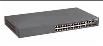
Figure 7-1 Ethernet switch
TS7700 grid adapters
The connection paths between multiple TS7700 clusters in a grid configuration are the two grid adapters in slot one of the I/O expansion drawers. The dual-ported 1 gigabit per second (Gbps) Ethernet adapters can be copper RJ45 or optical fiber (shortwave (SW)). These optical adapters have an LC duplex connector.
Depending on your bandwidth and availability needs, TS7700 can be configured with two or four 1-Gb links. Feature Code 1034 (FC1034) is needed to enable the second pair of ports in the grid adapters. These ports can be either fiber SW or copper. Optionally, there is a choice of two longwave (LW) single-ported Optical Ethernet adapters (FC1035) for two or four 10-Gb links. Your network infrastructure must support 10 Gbps for this selection. The adapter does not scale down to 1 Gbps.
The Ethernet adapters cannot be intermixed within the same cluster, they must be of the same type (same feature code).
Disk encryption
The latest TS7700 cache models, 3956-CC9/CS9, 3956-CS9/XS9, and 3956-CSA/XSA, support full disk encryption (FDE). All cache controllers and cache drawers must be encryption capable in order for FDE to be activated. With FDE, data is secure at the most basic level – the hard drive. FDE covers most data exposures and vulnerabilities all at once.
FDE simplifies security planning and provides unparalleled security assurance with government-grade encryption. FDE uses the Advanced Encryption Standard (AES) 256 bit encryption to protect the data. This algorithm is approved by the US government for protecting secret-level classified data. Data is protected through the hardware lifecycle and enables return of defective drives for servicing. It also allows for quick decommission or repurposing of drives with instant cryptographic erase.
FDE preserves performance because the encryption is hardware-based in the disk drive. FDE doesn’t slow the system down because the encryption engine matches the drive’s maximum port speed and scales as more drives are added. In order for drive-level encryption to provide this value, the key that enables encryption must be protected and managed.
There are two types of keys that are used with the FDE drives. The data encryption key is generated by the drive and never leaves the drive, so it always stays secure. It is stored in an encrypted form within the drive and performs symmetric encryption and decryption of data at full disk speed with no effect on disk performance. Each FDE drive uses its own unique encryption key, which is generated when the disk is manufactured and regenerated when required by the SSR.
The lock key or security key is a 32-byte random number that authenticates the drive with the CC9/CS9/CSA Cache Controller by using asymmetric encryption for authentication. When the FDE drive is secure enabled, it must authenticate with the CC9/CS9/CSA Cache Controller or it does not return any data and remains locked.
After the drive is authenticated, access to the drive operates like an unencrypted drive. One security key is created for all FDE drives attached to the CC9/CS9/CSA cache controller and CX9/XS9/CSA Cache Expansion drawers. The authentication key is generated, encrypted, and hidden in the subsystem (NVSRAM) of the CC9/CS9/CSA Cache Controller in each of the two CECs. The TS7700 stores a third copy in the Vxx persistent storage disks. A method is provided to securely export a copy to DVD.
The authentication typically occurs only after the FDE starts, where it will be in a “locked” state. If encryption was never enabled (the lock key is not initially established between the CC9/CS9/CSA Cache Controller and the disk), the disk is considered unlocked with access unlimited, as in a non-FDE drive.
The lock key or security key is set up by the SSR using the SMIT panels. There are two feature codes that are required to enable FDE. Feature Code 7404 is required on all 3956-CC9, 3956-CX9, 3956-CS9, 3956-XS9, 3956-CSA, and 3956-XSA cache drawers.
In addition, the following feature codes are required:
•FC7330 is required on the 3952-F05 base frame for a TS7740.
•FC7331 is required on the 3952-F05 base frame for a TS7720.
•FC7332 is required on the 3952-F05 Expansion frame for a TS7720.
•FC7333 is required on the 3952-F06 base frame for a TS7760.
•FC7334 is required on the 3952-F06 Expansion frame for a TS7760.
Through the SMIT menus, the SSR can “Re-generate Encryption Key” on the cache subsystem disks by requesting the FDE drives to erase their data encryption key and generate a new one. After FDE is enabled, it cannot be disabled.
Starting with R3.3 code, the TS7700 can use external key management with 3956-CC9 and 3956-CS9 cache types. Similarly, R4.1 adds the same functionality with 3956-CSA. Feature codes 5276 and 5277 are required to enable the external management. Systems that are already set up with Local encryption key management can be converted to external key management.
Back-end drive 16 Gbps fibre switch
|
Note: Only IBM Security Key Lifecycle Manager (SKLM) supports both external disk encryption and TS1140 and TS1150 tape drives. The settings for Encryption Server are shared for both tape and external disk encryption.
The IBM Security Key Lifecycle Manager for z/OS (ISKLM) external key manager supports TS7700 physical tape, but does not support TS7700 disk encryption.
|
Release 4.1 includes support for TS7740/TS7720T/TS7760T to attach to a TS4500 library. R4.1 also includes support for a new 16 Gbps fibre switch that can be used to communicate with the back-end tape drives. The TS7700 16 Gbps fibre switch can be housed in a 3584-LXX or 3584-DXX frame. TS7740/TS7720T/TS7760T can use the new 16 Gbps fibre switch attached to either a TS3500 or TS4500.
The switches can be in a frame that contains some of the associated back-end drives, or can reside in a frame that does not contain any of the associated drives. The switches are placed at the bottom of the tape library frame. The fibre patch panel must be removed from the frame if it has one.
A frame that contains the back-end switches can still house up to 12 or 16 drives (Based on TS3500 or TS4500). Feature code 4879 supplies the mounting hardware for the back-end switches and a pair of dressed eight fiber cable trunks to connect the back-end switches to the associated back end drives in the frame.
Only eight pairs are supplied in the trunks because the preferred practice for TS7740/TS7720T/TS7760T drive placement states that the drives should be split evenly between two frames. Drives that do not attach to the back-end switches must be cabled directly to the drives, because the patch panel has been removed.
|
Note: The TS7760T does not support 4 Gbps and 8 Gbps fiber switches for connection to the back-end drives. Currently, a TS7760T must use the 16 Gbps fiber switch to connect to the back-end drives.
|
Table 7-1 lists the feasible combination of TS7700, TSx500, and the necessary switches.
Table 7-1 Combination of TS7700, TSx500, and the necessary switches
|
Machine with code R4.1
|
TS3500 with 4 or 8 Gb
drive switch
|
TS3500 with 16 Gb drive switch1
|
TS4500 with 16 Gb drive switch
|
|
TS7760T
|
N/A
|
Homogeneous with
all generation drives
|
Heterogeneous with TS1150 and TS1140
|
|
TS7720T/TS7740
|
All configurations as supported in R3.3
|
All configurations as supported in R3.3
|
Heterogeneous with TS1150 and TS1140
|
1 TS3500 top rack required due to size of switches
7.1.2 TS7760 components
This section describes the TS7760 components. Figure 7-2 shows the frame layout for a manufacturer-installed TS7760.

Figure 7-2 Single frame layout of a TS7760
Figure 7-3 shows the frame layout for a TS7760 Storage Expansion Frame.

Figure 7-3 Layout of a TS7760 Storage Expansion Frame with 3956-CSA and 3956-XSA
The TS7760 Storage Expansion Frame is a 3952 Tape Frame that is designated as a cache expansion frame for use with a fully configured TS7700 Base Frame.
The TS7760 Storage Expansion Frame enables expansion of the TS7760 Cache by attaching of up to two more storage frames. Each frame contains one extra TS7760 Cache Controller and optional TS7760 Cache Drawers. Additionally, 8 TB disk drives were introduced in R4.1. For more information, see 7.2.3, “TS7760 Cache upgrade options” on page 274.
The distance between a TS7760 Storage Expansion Frame and the TS7700 Base Frame cannot exceed 10 meters. This distance enables connection of the frames by using a 30-meter fibre cable.
TS7760 Server model (3957-VEC)
The TS7760 Server comprises a server and two I/O expansion drawers for PCIe adapters. The TS7760 Server controls virtualization processes such as host connectivity, device virtualization, and hierarchical storage management (HSM) functions such as storage, replication, and organization of data across physical media and libraries.
The TS7700 Server (3957-VEC) offers the following features:
•Two 10-core 3.42 GHz POWER8 processor cards
•Processor card and memory configuration (using only 2 x 16 GB DDR3 DIMMs):
– 32 GB total memory with 1 processor card and 20 cores
•Another SAS controller with support for RAID 0, 1, 5, 6, and 10
•8 SFF 300 GB SAS internal drives using RAID 0
•1 Gb or 10 Gb Ethernet
•Four USB ports:
– Two USB 3.0 ports for general use
– Two USB 2.0 ports for the FSP service processor
•One system (serial) port with RJ45 connector
•Two Hardware Management Console (HMC) ports
•Extended Error Handling (EEH) and hot plug support on PCI expansion slots
•Two 6-drive SAS bays
•One slim line DVD RAM drive
Each Expansion I/O adapter drawer offers the following features:
•Six additional hot-pluggable PCIe cartridge style slots (used to house FICON adapters for host attachment, Fibre Channel adapters for cache drawer attachment, Fibre Channel adapters for tape communication, and Ethernet adapters for grid communication).
•Redundant AC power
•Redundant cooling
•Concurrent maintenance of:
– PCIe or PCI-X adapters
– Two power supplies
– Two fans
Figure 7-4 and Figure 7-5 show the TS7700 Server System Unit.

Figure 7-4 TS7700 Server (3957-VEC) System Unit (front view)
Figure 7-5 shows the rear view of the unit.

Figure 7-5 TS7700 Server (3957-VEC) System Unit (rear view)
Figure 7-6 shows the TS7700 Server Expansion Unit I/O drawer.

Figure 7-6 TS7700 Server Expansion Unit I/O drawer (rear view)
TS7760 Cache Controller
The TS7760 Cache Controller is a self-contained 2U enclosure that mounts in the 3952 Tape Frame. The TS7760 Cache Controller provides dynamic disk pools-protected virtual volume disk storage for fast retrieval of data from cache. The TS7760 Cache Controller offers the following features:
•Two Fibre Channel processor cards
•CPU microprocessor
•Two battery backup units (one for each processor card)
•Two AC power supplies with imbedded enclosure cooling units
•12 DDMs, each with a storage capacity of 4 TB or 8 TB
•Supports Advanced Encryption Standard (AES) 256-bit encryption
•Optional attachment to a maximum of nine TS7760 Cache Drawers in a TS7760 Base Frame
•Optional attachment to up to 15 TS7760 Cache Drawers (3956-XSA), each containing 12 DDMs with a storage capacity of 4 TB or optional attachment to up to 14 TS7760 Cache Drawers (3956-XSA), each containing 12 DDMs with a storage capacity of 8 TB
•12 Gb SAS port
•Dual active 16 Gb Fibre Channel connectivity to server 3957-VEC
Figure 7-7 shows the TS7760 Cache Controller from the front.

Figure 7-7 TS7760 Cache Controller 3956-CSA (front view)
Figure 7-8 shows the TS7760 Cache Controller from the rear.

Figure 7-8 TS7760 Cache Controller 3956-CSA (rear view)
TS7760 Cache Drawer
The TS7760 Cache Drawer is a self-contained 2U enclosure that mounts in the 3952 Tape Frame.
The TS7760 Cache Drawer expands the capacity of the TS7760 Cache Controller by providing additional dynamic disk pools-protected disk storage. Each TS7760 Cache Drawer offers the following features:
•Two Environmental Services Module (ESM) cards
•Two AC power supplies with embedded enclosure cooling units
•12 DDMs, each with a storage capacity of 4 TB or 8 TB
•Supports Advanced Encryption Standard (AES) 256-bit encryption
•Attachment to the TS7760 Cache Controller
Figure 7-9 shows the TS7760 Cache drawer from the front.

Figure 7-9 TS7760 Cache Drawer 3956-XSA (front view)
Figure 7-10 shows the TS7760 Cache drawer from the rear.

Figure 7-10 TS7760 Cache Drawer 3956-XSA (rear view)
7.1.3 TS7720 components
The TS7720 provides most of the benefits of the TS7740 without physical tape attachment.
The TS7720 consists of a 3952 Model F05 Encryption Capable Base Frame and one or two optional 3952 Model F05 Encryption Capable Storage Expansion Frames. FC5272 enables FDE on the VEB. FC7404 is needed to enable FDE on each cache drawer. After it is enabled, FDE cannot be disabled.
The 3952 Model F05 Tape Base Frame houses the following components:
•One TS7720 Server, 3957 Model VEB.
•One TS7700 I/O Expansion Drawer (primary and alternative).
•One TS7720 Encryption Capable 3956-CS9 Cache Controller Drawer. The controller drawer has 0 - 9 TS7720 Encryption Capable 3956- XS9 Cache Expansion Drawers. The base frame must be fully configured before you can add a first storage expansion frame.
•Two Ethernet switches.
The 3952 Model F05 Storage Expansion Frame houses one TS7720 Encryption Capable 3956-CS9 Cache Controller Drawer. Each controller drawer can have 0 - 15 TS7720 Encryption Capable 3956-XS9 Cache Expansion Drawers. The first expansion frame must be fully configured before you can add a second storage expansion frame.
The base frame, first expansion frame, and second expansion frame are not required to be of the same model and type. Only when the base frame is of the CS9 type is it required to be fully populated when you add an expansion frame. When you add a second expansion frame, the first expansion frame must be fully populated if it contains CS9 technology.
Using 3 TB HDDs, the maximum configurable capacity of the TS7720 at Release 3.2 or later with the 3952 Model F05 Storage Expansion Frame is 1007.86 TB of data before compression.
Figure 7-11 shows the TS7720 Base Frame components.
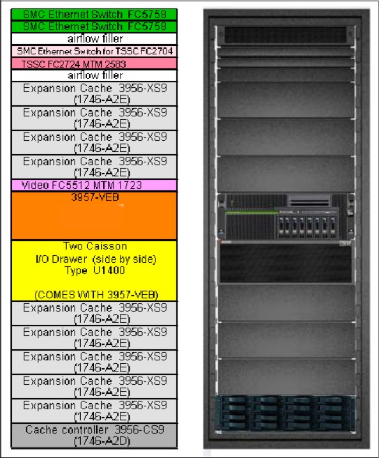
Figure 7-11 TS7720 Base Frame components
Figure 7-12 shows the TS7720 Expansion Frame components.

Figure 7-12 TS7720 Expansion Frame components
TS7720 Server model (3957-VEB)
The server consists of an IBM System POWER7 processor-based server and an expansion I/O drawer (primary and alternative) containing PCIe adapters. This replaces the original IBM POWER® 5 ++ and the I/O drawer from the V06/VEA version. The TS7700 Server controls virtualization processes, such as host connectivity and device virtualization. It also controls the internal hierarchical storage management (HSM) functions for logical volumes and replication.
Figure 7-13 shows the front view of the TS7700 Server models 3957-VEB.

Figure 7-13 TS7700 Server models 3957-VEB (front view)
The TS7700 Server VEB offers the following features:
•Rack-mount (4U) configuration.
•One 3.0-gigahertz (GHz) 8-core processor card.
•16 GB of 1066 MHz error-checking and correcting (ECC) memory (32 GB when 8-Gb Fibre Channel connection (FICON) is present).
•Integrated features:
– Service processor
– Quad-port 10/100/1000 megabits (Mb) Ethernet
– IBM EnergyScale™ technology
– Hot-swap capability and redundant cooling
– Two system (serial) ports
– Two Hardware Management Console (HMC) ports
– Two system power control network (SPCN) ports
– One slim bay for a DVD-RAM
•Five hot-swap slots:
– Two PCIe x8 slots, short card length (slots 1 and 2)
– One PCIe x8 slot, full card length (slot 3)
– Two PCI-X DDR slots, full card length (slots 4 and 5)
The hot-swap capability is only for replacing an existing adapter with another of the same type. It is not available if you change adapter types in a machine upgrade
or change.
or change.
•SAS HDD: The TS7700 uses eight HDDs. Four disks mirror one SAS adapter, and the other four backup drives are assigned to a separate SAS adapter.
•A SAS card is used for the mirroring and SAS controller redundancy. It has an external cable for accessing the mirrored disks.
Each I/O expansion Drawer offers six extra PCI Express adapter slots:
•One or two 4 Gb FICON adapters per I/O Expansion Drawer, for a total of two or four FICON adapters per cluster. Adapters can work at 1, 2, or 4 Gbps. FICON card must be of the same type within one cluster.
•One or two 8 Gb FICON adapters per I/O Expansion Drawer, for a total of two or four FICON adapters per cluster. Adapters can work at 2, 4, or 8 Gbps.
The FICON card must be of the same type within one cluster. 8 Gb FICON card requires FC 3462, 16 GB memory upgrade. All servers with 8 Gb FICON adapters require 32 GB of memory, an increase of 16 GB of memory to the default server configuration.
•Grid Ethernet card (PCI Express). Grid Ethernet can be copper or fiber (1 or 10 Gbps).
•8 Gbps Fibre Channel to disk cache (PCI Express).
•8 Gbps Fibre Channel PCI Express connection to tape in a TS7740 and TS7720T or
8 Gbps Fibre Channel PCI Express for connection to TS7720 Expansion frames.
8 Gbps Fibre Channel PCI Express for connection to TS7720 Expansion frames.
TS7720 Cache Controller (3956-CS9)
The TS7720 Encryption Capable 3956-CS9 Cache Controller Drawer is a self-contained 2U enclosure. It mounts in the 3952 Tape Base Frame and the optional 3952 Storage Expansion Frame. Figure 7-14 shows the TS7720 Cache Controller Drawer from the front (left side) and rear (right side). The rear view details the two separated controllers that are used for access redundancy and performance (Controller A on left and Controller B on the right side).

Figure 7-14 TS7720 Encryption Capable Cache Controller, 3956-CS9 (front and rear views)
The TS7720 Cache Controller provides RAID 6 protection for virtual volume disk storage, enabling fast retrieval of data from cache.
The TS7720 Cache Controller Drawer offers the following features:
•Two 8 Gbps Fibre Channel processor cards
•Two battery backup units (one for each processor card)
•Two power supplies with embedded enclosure cooling units
•Twelve disk drive modules (DDMs), each with a storage capacity of 3 TB, for a usable storage capacity of 23.86 TB
•Configurations with only CS9 controllers support one, two, or three TS7720 Cache Controllers:
– All configurations provide one TS7720 Cache Controller in the 3952 Tape Base Frame. The 3952 Tape Base Frame can have 0 - 9 TS7720 Encryption Capable SAS Cache Drawers, 3956 Model XS9.
– All configurations with the optional 3952 Storage Expansion Frame provide one extra TS7720 Encryption Capable Cache Controller, 3956 Model CS9. When the second is added, an extra set of 8 Gb FC adapters is also added. The 3952 Storage Expansion Frame can have 0 - 15 TS7720 Encryption Capable SAS Cache Drawers, 3956 Model XS9.
TS7720 Cache Drawer (3956-XS9)
The TS7720 Encryption Capable Cache Drawer is a self-contained 2U enclosure. It mounts in the 3952 Tape Base Frame and in the optional 3952 Storage Expansion Frame. Figure 7-15 shows the TS7720 Cache Drawer from the front (left side) and rear (right side). It offers attachment to the TS7720 Encryption Capable Cache Controller.

Figure 7-15 TS7720 Encryption Capable Cache Drawer (front and rear views)
The TS7720 Cache Drawer expands the capacity of the TS7720 Cache Controller by providing extra RAID 6-protected disk storage. Each TS7720 Cache Drawer offers the following features:
•Two 8 Gb Fibre Channel processor cards
•Two power supplies with embedded enclosure cooling units
•Eleven DDMs, each with a storage capacity of 3 TB, for a usable capacity of 24 TB
per drawer
per drawer
The TS7720 disk-only can be used to write tape data that does not need to be copied to physical tape, which enables access to the data from the Tape Volume Cache (TVC) until the data expires.
The TS7720T enables a TS7720 to act like a TS7740 to form a virtual tape subsystem to write to physical tape. Full disk and tape encryption are supported. It contains the same components as the TS7720 disk-only. In a TS7720 disk-only configuration, the Fibre Channel ports are used to communicate with the attached cache, whereas in a TS7720T configuration, two of the Fibre Channel ports are used to communicate with the attached tape drives.
7.1.4 TS7740 components
The TS7740 combines the TS7700 with a tape library to form a virtual tape subsystem to write to physical tape. Since Release 3.2, TS7740 plant-built configurations include these components:
•One TS7740 Server, 3957 Model V07.
•One TS7740 Encryption Capable 3956-CC9 Cache Controller Drawer.
•The controller drawer has a maximum of three attached Encryption Capable 3956-CX9 Cache Expansion Drawers.
The total usable capacity of a TS7740 with one 3956-CC9 and two 3956-CX9s is approximately 28 TB before compression.
The Model CX9s can be installed at the plant or in an existing TS7740.
Figure 7-16 shows a summary of the TS7740 components.

Figure 7-16 TS7740 components
TS7740 Server model (3957-V07)
The detailed hardware of the TS7740 server 3957-V07 is that same as the TS7720 server 3957-VEB. For more information, see “TS7720 Server model (3957-VEB)” on page 260.
TS7740 Cache Controller (3956-CC9)
The TS7740 Encryption Capable Cache Controller is a self-contained 2U enclosure that mounts in the 3952 Tape Frame.
Figure 7-17 shows the front and rear views of the TS7740 Encryption Capable 3956-CC9 Cache Controller Drawer.
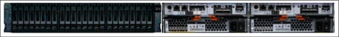
Figure 7-17 TS7740 Encryption Capable Cache Controller Drawer (front and rear views)
Figure 7-18 shows the rear view, detailing the two separated controllers that are used for access redundancy and performance (Controller A and Controller B).

Figure 7-18 TS7740 Encryption Capable Cache Controller (rear view)
The TS7740 Encryption Capable Cache Controller Drawer provides RAID 6-protected virtual volume disk storage. This storage temporarily holds data from the host before writing it to physical tape. When the data is in the cache, it is available for fast retrieval from the disk.
The TS7740 Cache Controller Drawer offers the following features:
•Two 8 Gbps Fibre Channel processor cards
•Two battery backup units (one for each processor card)
•Two power supplies with embedded enclosure cooling units
•Twenty-two DDMs, each possessing 600 GB of storage capacity, for a usable capacity of 9.45 TB
•Optional attachment to one or two TS7740 Encryption Capable 3956-CX9 Cache Expansion Drawers
TS7740 Cache Expansion Drawers (3956-CX9)
The TS7740 Encryption Capable Cache Expansion Drawer is a self-contained 2U enclosure that mounts in the 3952 Tape Frame.
Figure 7-19 shows the front view and the rear view of the TS7740 Encryption Capable 3956-CX9 Cache Expansion Drawer.

Figure 7-19 TS7740 Encryption Capable Cache Drawer (front and rear views)
The TS7740 Encryption Capable Cache Expansion Drawer expands the capacity of the TS7740 Cache Controller Drawer by providing extra RAID 6 disk storage. Each TS7740 Cache Expansion Drawer offers the following features:
•Two Environmental Service Modules (ESMs)
•Two power supplies with embedded enclosure cooling units
•22 DDMs, each with 600 GB of storage capacity, for a total usable capacity of 9.58 TB per drawer
•Attachment to the TS7740 Encryption Capable 3956-CC9 Cache Controller Drawer
7.1.5 TS7700 tape library attachments, drives, and media
In TS7700 configurations, the TS7740, TS7720T, and TS7760T are used with an attached tape library. The TS7740, TS7720T, and TS7760 must have their own logical partitions (LPARs) within the TS3500 or TS4500 tape library, with dedicated tape drives and tape cartridges.
Tape libraries
A TS7740, TS7720T, or a TS7760T attached to a TS3500 or TS4500 tape library interfaces directly with tape drives in the library.
When attached to a TS3500 or TS4500 tape library, the TS7700 can attach only to 3592 Tape Drives. Up to 16 3592 Tape Drives can be attached.
Communication, control, and data signals travel along Fibre Channel connections between the TS7700 and tape drives contained in the TS3500 or TS4500 tape library. A pair of Fibre Channel switches routes the data to and from the correct tape drive.
|
Note: TS1140 EH7 tape drives and TS1150 EH8 tape drives are used with the TS4500 tape library. All other tape drives are used with the TS3500 tape library.
|
Tape drives
The 3592 Tape Drives supported for use with the TS7740, TS7720T, and TS7760T include:
•TS1150 Tape Drive
•TS1140 Tape Drive
•TS1130 Tape Drives
•TS1120 Tape Drives (in native mode and emulating 3592 J1A Tape Drives)
•3592 J1A Tape Drives
Tape media
The TS7740 and TS7720T support the following types of media:
•3592 Tape Cartridge (JA)
•3592 Expanded Capacity Cartridge (JB)
•3592 Advanced Type C Data (JC)
•3592 Advanced Type D Data (JD)
•3592 Economy Tape Cartridge (JJ)
•3592 Advanced Type K Economy (JK)
•3592 Advanced Type L Economy (JL)
For more information, see “Tape drives and media support (TS7740,TS7720T, and TS7760T)” on page 141.
7.1.6 TS3000 Total System Storage Console
The TS3000 TSSC connects to multiple Enterprise Tape Subsystems, including TS3500/TS4500 tape libraries, 3592 Controllers, and the TS7700. The TS3000 TSSC is a required component for the TS7700. It can be a new console or an existing TSSC. A new TSSC can be installed in the TS7700 3952 Tape Base Frame or another existing rack.
All of these devices are connected to a dedicated, private local area network (LAN) that is owned by TSSC. Remote data monitoring of each one of these subsystems is provided for early detection of unusual conditions. The TSSC sends this summary information to IBM if something unusual is detected and the Call Home function has been enabled.
|
Note: For Call Home and remote support since TS7700 R3.2, an internet connection is necessary.
|
For IBM TS7700 R4.1, the following features are available for installation:
• FC 2704, TS3000 System Console expansion 26-port Ethernet switch/rackmount
• FC 2715, Console attachment
• FC 2725, Rackmount TS3000 System Console
• FC 2748, Optical drive
For more information, see Appendix A, “Feature codes and RPQ” on page 817.
7.1.7 Cables
This section describes the cable feature codes for attachment to the TS7700, extra cables, fabric components, and cabling solutions.
Required cable feature codes
The following cable feature codes are needed for attachment to the TS7700.
A TS7700 Server with the FICON Attachment features (FC 3441, FC 3442, FC 3443, FC 3438, FC 3439, FC 3402 or FC 3403) can attach to FICON channels of IBM Z components by using FICON cable features ordered on the TS7700 Server.
One cable must be ordered for each host system attachment by using the following cable features:
•FC3441 (4 Gb FICON Short-Wavelength Attachment) feature: The FICON shortwave-length adapter that is included with FC 3441 has an LC Duplex connector. It can connect to FICON short-wavelength channels of IBM Z components by using a 50-micron or 62.5-micron multimode fiber cable. At 4 Gbps, the maximum fiber cable length that is allowed by 50-micron cable is 150 m, or 55 m if you use a 62.5-micron cable.
•FC 3442 and FC 3443, 4-Gb FICON Long-Wavelength Attachment feature: The FICON long-wavelength adapter that is included with FC 3442 (4-Gb FICON Long-Wavelength Attachment) or FC 3443 (4 Gb FICON 10-kilometer (km) Long-Wavelength Attachment) has an LC Duplex connector. It can connect to FICON long-wavelength channels of
IBM Z components by using a 9-micron single-mode fiber cable.
IBM Z components by using a 9-micron single-mode fiber cable.
The maximum fiber cable length is 4 KM (2.48 miles) for FC 3442 and 10 KM (6.2 miles) for FC 3443.
|
Requirement: 8-Gb FICON adapters require FC 3462 (16-GB memory upgrade) and TS7700 Licensed Internal Code R3.1 or later.
|
•FC 3438 (8 Gb FICON Short Wavelength Attachment) provides one short-wavelength FICON adapter with an LC Duplex connector for attachment to a FICON host system shortwave (SW) channel by using a 50 micron or 62.5-micron multimode fiber cable. Each FICON attachment can support up to 512 logical channels. At 8 Gbps speed, the total cable length cannot exceed the following lengths:
– 150 meters using 50-micron OM3 (2000 MHz*km) Aqua blue-colored fiber
– 50 meters using 50-micron OM2 (500 MHz*km) Orange-colored fiber
– 21 meters using 62.5-micron OM1 (200 MHz*km) Orange-colored fiber
•FC 3439 (8 Gb FICON Long Wavelength Attachment) provides one long-wavelength FICON adapter, with an LC Duplex connector, for the attachment to a FICON host system long wave channel that uses a 9-micron single-mode fiber cable. The total cable length cannot exceed 10 km. Each FICON attachment can support up to 512 logical channels.
•FC 3402 (16 Gb FICON Short Wavelength Attachment) provides one short-wavelength FICON adapter with an LC Duplex connector for attachment to a FICON host system shortwave (SW) channel by using a 50 micron or 62.5-micron multimode fiber cable. Each FICON attachment can support up to 512 logical channels. At 16 Gbps speed, the total cable length cannot exceed the following lengths:
– 130 meters using 50-micron OM4 (47000 MHz*km) Aqua blue-colored fiber
– 100 meters using 50-micron OM3 (500 MHz*km) Orange-colored fiber
– 35 meters using 50-micron OM2 (500 MHz*km) Orange-colored fiber
•FC 3403 (16 Gb FICON Long Wavelength Attachment) provides one long-wavelength FICON adapter, with an LC Duplex connector, for the attachment to a FICON host system long wave channel that uses a 9-micron single-mode fiber cable. The total cable length cannot exceed 10 km. Each FICON attachment can support up to 512 logical channels.
|
Requirement: FC 3401 (Enable 8 Gb or 16 Gb FICON dual port) enables the second port on each installed 8-Gb FICON adapter.
|
Extra cables, fabric components, and cabling solutions
Conversion cables from SC Duplex to LC Duplex are available as features on IBM Z platforms if you are using cables with SC Duplex connectors that now require attachment to fiber components with LC Duplex connections. Extra cable options, along with product support services, such as installation, are offered by IBM Global Technology Services.
See the IBM Virtualization Engine TS7700 Introduction and Planning Guide, GA32-0568, for Fibre Channel cable planning information.
If Grid Enablement (FC4015) is ordered, Ethernet cables are required for the copper/optical 1 Gbps and optical LW adapters to attach to the communication grid.
7.2 TS7700 component upgrades
Several field-installable upgrades give an existing TS7700 more functions or capacities. This section reviews the TS7700 component FC upgrades.
7.2.1 TS7700 concurrent system component upgrades
Concurrent system upgrades can be installed while the TS7700 is online and operating. The following component upgrades can be made concurrently to an onsite TS7700:
•Enable 1 TB Active Premigration Queue capacity (FC 5274).
Each instance of FC 5274 (Enable 1 TB Active Premigration Queue Capacity) enables up to 1 TB of data to be pending migration to physical tape or cloud storage tier. Up to 10 instances can be installed.
•Enable 5 TB Active Premigration Queue Capacity (FC 5279).
Each instance of FC 5279 (Enable 5 TB Active Premigration Queue Capacity) enables up to 5 TB of data to be pending migration to physical tape or cloud storage tier. Up to 10 instances can be installed after 10 instances of FC 5274 are installed for a active premigration queue size to 60 TB and higher.
•Incremental disk cache capacity enablement (TS7740 only).
You can add a 1 TB (0.91 tebibytes (TiB)) increment of disk cache to store virtual volumes, up to 28 TB (25.46 TiB). Use FC 5267 (1 TB cache enablement) to achieve this upgrade.
•Enable 8 Gb or 16 Gb FICON second port. Use FC 3401.
•Incremental data throughput.
You can add a 100 MBps increment of peak data throughput, up to your system’s hardware capacity. When the maximum number of performance increments are installed, the system no longer restricts performance. Use FC 5268 (100 MBps increment) to achieve this upgrade.
Peak data throughput increments of 100 MBps are available as transferred from a host to a vNode before compression. If more peak data throughput capacity is needed, up to 10 more increments can be ordered for the 3957-V07/VEB when FC 3441/3442/3443
(4 Gb FICON) is installed, or up to 24 can be ordered for the 3957-V07/VEB/VEC when FC 3438/3439 (8 Gb FICON) is installed (to complement FC 9268, Plant installation of 100 MBps throughput installed at the plant). The 3957-VEC with FC 3402/3403 (16 Gbps FICON) allows a max of 40 performance increments.
(4 Gb FICON) is installed, or up to 24 can be ordered for the 3957-V07/VEB/VEC when FC 3438/3439 (8 Gb FICON) is installed (to complement FC 9268, Plant installation of 100 MBps throughput installed at the plant). The 3957-VEC with FC 3402/3403 (16 Gbps FICON) allows a max of 40 performance increments.
If the maximum number of increments is installed, the TS7700 places no limits on data transfers through the cluster. This installation is performed by you through the TS7700 Management Interface by entering the license key that is obtained with the purchase of FC 5268, 100 MBps increment.
|
Note: All host data transfers through the TS7740 Cluster are considered for the data transfer limit regardless of which TS7740 Cluster initiated or received the data transfer.
|
•Selective Device Access Control.
You can grant exclusive access to one or more logical volume ranges by only certain logical control units (LCUs) or subsystem IDs within a composite library for host-initiated mounts, ejects, and changes to attributes or categories. Use FC 5271, Selective Device Access Control (SDAC) to add this upgrade.
Each instance of this feature enables the definition of eight selective device access groups. The default group provides a single access group, resulting in nine total possible access groups. This feature is available only with a Licensed Internal Code level of 8.20.0.xx or later.
|
Consideration: The feature must be installed on all clusters in the grid before the function becomes enabled.
|
•Increased logical volumes.
The default number of logical volumes that is supported is 1,000,000. You can add support for extra logical volumes in 200,000 volume increments by using FC 5270. Up to a total of 4,000,000 logical volumes are supported by the maximum quantity of 15 FC 5270 components.
|
Remember: The number of logical volumes that are supported in a grid is set by the cluster with the smallest number of FC 5270 increments installed.
When joining a cluster to an existing grid, the joining cluster must meet or exceed the currently supported number of logical volumes of the existing grid.
When merging one or more clusters into an existing grid, all clusters in the ending grid configuration must contain enough FC 5270 increments to accommodate the sum of all post-merged volumes.
|
•Dual-port grid connection.
You can concurrently enable the second port of each dual port, 1 Gb grid connection adapter in the following TS7700 Server configurations:
– On a 3957-V07, 3957-VEB, or 3957-VEC when FC 1036 (1 Gb grid dual port copper connection) or FC 1037 (1 Gb dual port optical SW connection) are present.
– On a 3957-VEC when FC 1038 (10 Gb dual port optical LW connection) is present.
Use FC 1034 (Enable dual port grid connection) to achieve these upgrades.
|
Note: A non-concurrent install is required to change grid adapters to a different configuration.
|
•Disk encryption.
You can encrypt the DDMs within a TS7700 disk storage system.
•TS7700 Storage Expansion frame.
You can add up to two cache expansion frames to a fully configured TS7760 using FC 9323 (Expansion frame attachment) and applying FC 7334 (TS7700 Encryption-capable expansion frame) to a 3952 F06 Tape Frame.
|
Note: The adapter installation (FC 5241, Dual port FC HBA) is non-concurrent.
|
7.2.2 TS7700 non-concurrent system component upgrades
A multi-cluster GRID configuration can enable practically all changes or upgrades to be concurrent from a client’s standpoint, putting one individual member in service at a time. In a stand-alone cluster configuration, non-concurrent upgrades require the TS7700 to be brought offline before installation. In certain instances, the targeted component must be reconfigured before the upgrade takes effect. The component upgrades listed in the following sections must be made non-concurrently to an existing TS7700:
•TS7760C enable connection to cloud storage - refer to the IBM TS7760 R4.2 Cloud Storage Tier Guide, REDP-5514
•TS7720 /TS7760 enable tape attach
For TS7720 /TS7760 servers (VEB/VEC hardware), use the following features to upgrade and enable the server to attach to a tape library:
– FC 5273 (TS7720/TS7760 Tape Attach enablement)
– FC 5274 (Enable 1 TB Pending Tape Capacity)
Before installing the features, ensure that all hardware and microcodes prerequisites are met. In addition, you should plan the future usage of the TS7700T and prepare the necessary information ahead. After the upgrade is installed, you need to update the information on the MI.
– Number of tape partitions: Depending on the usage decision, you might want to introduce multiple tape partitions, either for different customers, different LPARs (like prod, test, and development), or for different workload types.
– Size of the tape partitions: CP1 is the only tape partition that will be assigned during the upgrade. The origin tape partition size is 3 TB. Consider that currently all data is still in CP0, and if you do not redirect the workload to the CP1 the origin value is acceptable. However, you should adjust the size before you redirect the workload to CP1.
– Delay premigration limit: In each tape partition, you can define how much data with a “delay premigration” attribute can be stored.
– Storage Class updates: To direct workload to the Tape partitions, consider whether you want to introduce either new Storage Classes, or redirect the workload of existing Storage Classes to the CP1 partition.
– Storage Group: You might want to use different physical pools in the TS7700T. If so, you need dedicated Storage Groups to direct the data to the physical pool.
– Setup of the physical pool: You might want to specify the number of premigration drives, or the reclaim value in a physical pool. In addition, you might also want to introduce a Copy export pool. If so, you also need to update the appropriate Management Class.
– Set inhibit reclaim schedule: Depending on your workload, you might want to inhibit the reclaim at different schedules in the day or week.
– Adjust Settings: Adjust at least PMPRIOR and PMTHLVL (use the amount of FC 5274 for the PMTHLVL). We also strongly advise you to update the ALERT settings to ensure that alerts will be reported on several threshold levels.
– Update your automation to pick up the new Alert messages.
– After the upgrade, all data is still in CP0. If you want to move this data to a CPx partition, IBM provides a LI REQ PARTRFSH command to do so. However, plan the movement carefully. All data moved from a CP0 counts immediately to the premigration queue. Moving too much data concurrently fills up the premigration queue and can lead to throttling.
For detailed information about the LI REQ PARTRFSH command, see the IBM TS7700 Series z/OS Host Command Line Request User’s Guide:
•16 Gb FICON adapters
Only TS7760 model VEC supports 16 Gb FICON adapter in R4.1.2 or later. You can install up to four 16 Gb FICON adapters and enable the second port with FC 3401 on each adapter for a total of eight host ports. There can cannot be a intermix of adapters. FICON adapter replacement is non-concurrent when used with a 3957-VEC. Use FC 3402 (16 Gb FICON Short Wavelength Attachment) or FC 3403 (16 Gb FICON Long Wavelength Attachment) for this installation.
•8 Gb FICON adapters
You can install up to two 8 Gb FICON adapters or exchange adapters for another type (SW-to-LW or LW-to-SW) to connect a TS7700 Server (3957-V07, 3957-VEB, or 3957-VEC) to a host system. FICON adapter replacement is non-concurrent when used with a 3957-V07 or 3957-VEB. Use FC 3438 (8 Gb FICON Short Wavelength Attachment) or FC 3439 (8 Gb FICON Long Wavelength Attachment) for this installation.
You can also use FC 3401 (Enable 8 Gb FICON dual port) to enable a second 8 Gb FICON adapter port for double the number of host connections. The enablement of the second port is concurrent.
When replacing the 4 Gbps FICON cards with 8 Gbps FICON cards, make sure that you also examine the number of performance increments. If you are exceeding 1,000 MBps on your 4 Gbps machine, and you install 8 Gbps FICON without more throughput increments, you could actually reduce your peak performance. It is important to consider purchasing additional throughput increments when you upgrade to 8 Gbps FICON.
•4 Gb FICON adapters
You can install Fibre Channel (FICON) adapters to convert a two FICON configuration to a four FICON configuration, or to replace one pair of FICON adapters of a certain type with a pair of another type for SW (4 km (2.48 miles)) or LW (10 km (6.2 miles)). Replacement of an existing FICON adapter requires the removal of the original feature and addition of the new feature.
Use FC 3441, FICON short-wavelength attachment, FC 3442, FICON long-wavelength attachment, and FC 3443, FICON 10-km long-wavelength attachment for these upgrades.
•Ethernet adapters for grid communication:
– SW fiber Ethernet
You can add a 1 Gb shortwave fibre Ethernet adapter for grid communication between TS7700s.
For a TS7760 Server (3957-VEC) use FC 1037, 1 Gb dual port optical SW connection to achieve this upgrade.
For a 3957-V07 or 3957-VEB use FC 1037, 1 Gb dual port optical SW connection to achieve this upgrade.
– LW fiber Ethernet
You can add a longwave fibre Ethernet adapter for grid communication between TS7700s.
For a 3957-VEC use FC 1038, 10 Gb dual port optical LW connection to achieve this upgrade.
For a 3957-V07 or 3957-VEB use FC 1035, 10 Gb grid optical LW connection to achieve this upgrade.
|
Consideration: These 10 Gb adapters cannot negotiate down to run at 1 Gb. They must be connected to a 10 Gb capable network connection.
|
– Copper Ethernet
You can add a 1 Gbps copper Ethernet adapter for grid communication between TS7700 tape drives. On a 3957-V07, 3957-VEB, or 3957-VEC use FC 1036, 1 Gbps grid dual port copper connection to achieve this upgrade.
|
Clarification: On a TS7700, you can have two 1 Gbps copper Ethernet adapters or two 1 Gbps SW fiber Ethernet adapters or two 10 Gbps LW fiber Ethernet adapters (3957-V07, VEB, and VEC only) installed. Intermixing different types of Ethernet adapters within one cluster is not supported.
|
– TS7700 Server dual copper/optical Ethernet Adapter Card Conversion
You can convert a dual port grid Ethernet adapter in a TS7700 Server for a dual port adapter of the opposite type, by ordering FC 1036 (dual port copper) in exchange for a dual port optical Ethernet adapter FC 1037, or vice versa. In a similar way, you can order the 10 Gb grid LW adapter (FC 1035) in exchange for the 1 Gbps adapters (FC 1036 and FC 1037) and vice versa.
When you upgrade four 1 Gbps grid links to two 10 Gbps grid links, consult with your IBM SSR. Each grid link can communicate only to the corresponding grid link in other clusters in the grid. When one cluster upgrades four 1 Gbps grid links to two 10 Gbps grid links, only these two can communicate to the cluster with 4 times 1 Gbps.
The other two grid links will not be used any more, and will report link degradation hardware messages. Consider disabling these unused grid links until all the clusters upgrade to two 10 Gbps grid links.
•TS7720 Server Fibre Channel host bus adapter installation
You can install two Fibre Channel interface cards in the TS7760 Server (3957-VEC) to connect the TS7760 Server to the disk arrays in the TS7760 Storage Expansion Frame. Use FC 5242, Dual Port 16 Gb Fibre Channel HBA to achieve this installation.
You can install two Fibre Channel interface cards in the TS7720 Server (3957-VEB) to connect the TS7720 Server to the disk arrays in the TS7720 Storage Expansion Frame. Use FC 5241, Dual port FC HBA to achieve this installation.
•TS7700 Server physical memory upgrade
You can add 16 GB of physical memory to a 3957-V07 or 3957-VEB that contains 16 GB, for a resulting total of 32 GB of physical memory. Use FC 3462, 16 GB memory upgrade to achieve this upgrade.
•TS7740 to TS7760T frame replacement
This replaces a 3952 F05 frame containing a TS7740 3957-V06 (F05 with FC 5628) or a 3952 F05 frame containing a TS7740 3957-V07 (F05 with FC 5629) with 3952 F06 frame containing a TS7760 tape attach 3957-VEC.
16 Gb switches are required for TS7760T connectivity and R2.1 or above microcode is mandatory. Existing J1A/TS1120/TS1130/TS1140/TS1150 and the accompanying tape media can be retained.
•Additional Virtual Devices (FC5275)
Each instance of FC 5275 enables up to 16 additional virtual devices (virtual tape drives). The maximum number of features that is supported is 15 for a total of 496 virtual devices. If FC 5275 is installed on a cluster in a mixed GRID microcode level, the additional devices will not be available to the host until all cluster members are at 8.32.x.x or later.
When all cluster members are at 8.32.x.x or later, the cluster member with FC 5275 needs to be taken offline and back online. If this was done previously, while the cluster member had FC 5275 installed, there is no need to take the cluster back offline again.
To gain access to the new devices, the IODF needs to be modified. Additional control units with new libport-IDs need to be defined. This can either be done before or after the installation of the feature codes. For more information, see Appendix H, “Extra IODF examples” on page 919.
After the installation and activation of the FCs and the activation of the new IODF, you need to restart the OAM address space on all attached LPARs where the additional drives will be used to refresh the unit control blocks in OAM. Then you can vary online the drives to the LPARs.
If FC 5271 (Selective Device Access Enablement) is installed on the cluster the customer must need to include the new Library Port IDs into the Access port groups using the TS7700 Management Interface. If you do not include these in the appropriate access groups, the z/OS can select the device for a mount, but the TS7700 does not enable you to mount the virtual volume. The following message is displayed:
CBR4175I Volume volser library library-name access group denies mount
7.2.3 TS7760 Cache upgrade options
This section describes the TVC upgrade options that are available for the TS7760. If you want to implement encryption, see the feature codes in Appendix A, “Feature codes and RPQ” on page 817.
For the data storage values in TB versus TiB, see 1.6, “Data storage values” on page 12. The TS7760 Base frame minimum cache configuration is one CSA Cache Controller containing 12 DDMs, each with a storage capacity of 4 TB (3.63 TiB) or 8 TB (7.27 TiB). Optional attachment to a maximum of nine TS7760 Cache Drawers in a TS7760 Base Frame.
The TS7760 Storage Expansion Frame consists of one TS7760 Cache Controller (3956-CSA), containing 12 DDMs, each of which have a storage capacity of 4 TB or 8 TB. Optional attachment to up to 15 TS7760 Cache Drawers (3956-XSA), each containing 12 DDMs with a storage capacity of 4 TB or optional attachment to up to 14 TS7760 Cache Drawers (3956-XSA), each containing 12 DDMs with a storage capacity of 8 TB.
|
Note: FC 5659, Field installation of 3956-XSA, is the same as FC 5662, Field installation of 3956-XSA with 8 TB DDMs, in all aspects, except for the drives that are installed in the drawer.
If the TS7760/TS7760T has any 8 TB drives installed in a string, only 3957-XSA expansion drawers with 8 TB drives can be added. For example, if the 3957-CSA cache controller and the first 3957-XSA expansion drawer in the string contain 4 TB drives, but the second 3957-XSA expansion drawer contains 8 TB drives, every other 3957-XSA expansion drawer also must contain 8 TB drives.
If the cache string has an odd number of drawers (Controller + Expansion drawers) that contain 4 TB drives, FC 5659, Field installation of 3956-XSA, should be installed first. This configuration completes the dynamic disk pool (DDP), and ensures that all drawers in the pool contain the same size drives. If FC 5662, Field installation of 3956-XSA with 8 TB DDMs, is installed in this scenario, the 8 TB drives are configured to use only 4 TB of space to complete the DDP.
For example, if a TS7760/TS7760T has a 3956-CSA with two 3956-XSA expansion drawers (three total drawers) that contain 4 TB drives, the next drawer that is installed should be FC 5659, Field installation of 3956-XSA, which contains 4 TB drives.
|
Table 7-2 shows the TS7760 Storage Expansion Frame configurations for 4 TB capacity drives.
Table 7-2 TS7760 Storage Expansion Frame configurations using 4 TB drives
|
Cache configuration in a new TS7760
|
Cache units1 in eachTS7760 Storage Expansion Frame cache controller (3956-CSA) plus optional cache drawers (3956-XSA)
|
First TS7760 Storage Expansion Frame
|
Second TS7760 Storage Expansion Frame
|
||
|
Total cache units (including TS7760 Base Frame)
|
Available
capacity
|
Total cache units (including TS7760 Base Frame)
|
Available capacity
|
||
|
1 TS7760 Cache Controller (3956-CSA)
9 TS7760 Cache Drawers (3956-XSA)
|
1 (controller only)
|
11
|
345.07 TB
(313.84 TiB)
|
27
|
847.60 TB
(770.88 TiB)
|
|
2
|
12
|
376.49 TB
(342.42 TiB)
|
28
|
879.03 TB
(799.47 TiB)
|
|
|
3
|
13
|
407.92 TB
(371 TiB)
|
29
|
910.45 TB
(828.05 TiB)
|
|
|
4
|
14
|
439.35 TB
(399.59 TiB)
|
30
|
941.88 TB
(856.64 TiB)
|
|
|
5
|
15
|
470.78 TB
(428.17 TiB)
|
31
|
973.31 TB
(885.22 TiB)
|
|
|
6
|
16
|
502.21 TB
(456.76 TiB)
|
32
|
1004.74 TB
(913.80 TiB)
|
|
|
7
|
17
|
533.64 TB
(485.34 TiB)
|
33
|
1036.17 TB
(942.39 TiB)
|
|
|
8
|
18
|
565.06 TB
(513.92 TiB)
|
34
|
1067.60 TB
(970.97 TiB)
|
|
|
9
|
19
|
596.49 TB
(542.51 TiB)
|
35
|
1099.02 TB
(999.56 TiB)
|
|
|
10
|
20
|
627.92 TB
(571.09 TiB)
|
36
|
1130.45 TB
(1028.14 TiB)
|
|
|
11
|
21
|
659.35 TB
(599.67 TiB)
|
37
|
1161.88 TB
(1056.72 TiB)
|
|
|
12
|
22
|
690.78 TB
(628.26 TiB)
|
38
|
1193.31 TB
(1085.31 TiB)
|
|
|
13
|
23
|
722.21 TB
(656.84 TiB)
|
39
|
1224.74 TB
(1113.89 TiB)
|
|
|
14
|
24
|
753.63 TB
(685.43 TiB)
|
40
|
1256.17 TB
(1142.48 TiB)
|
|
|
15
|
25
|
785.06 TB
(714.01 TiB)
|
41
|
1287.59 TB
(1171.06 TiB)
|
|
|
16
|
26
|
816.49 TB
(742.59 TiB)
|
42
|
1319.02 TB
(1199.64 TiB)
|
|
1 The term Total cache units refers to the combination of cache controllers and cache drawers.
Table 7-3 shows the TS7760 Storage Expansion Frame configurations for 8 TB capacity
Table 7-3 TS7760 Storage Expansion Frame configurations using 8 TB capacity drives
|
Cache configuration in a new TS7760
|
Cache units1 in eachTS7760 Storage Expansion Frame cache controller (3956-CSA) plus optional cache drawers (3956-XSA)
|
First TS7760 Storage Expansion Frame
|
Second TS7760 Storage Expansion Frame
|
||
|
Total cache units (including TS7760 Base Frame)
|
Available
capacity
|
Total cache units (including TS7760 Base Frame)
|
Available capacity
|
||
|
1 TS7760 Cache Controller (3956-CSA)
9 TS7760 Cache Drawers (3956-XSA)
|
1 (controller only)
|
11
|
679.67 TB
(618.16 TiB)
|
26
|
1606.99 TB
(1461.55 TiB)
|
|
2
|
12
|
714.51 TB
(674.40 TiB)
|
27
|
1668.83 TB
(1517.80 TiB)
|
|
|
3
|
13
|
803.35 TB
(730.64 TiB)
|
28
|
1730.68 TB
(1574.04 TiB)
|
|
|
4
|
14
|
865.19 TB
(786.89 TiB)
|
29
|
1792.52 TB
(1630.28 TiB)
|
|
|
5
|
15
|
927.03 TB
(843.13 TiB)
|
30
|
1854.36 TB
(1686.53 TiB)
|
|
|
6
|
16
|
988.87 TB
(899.38 TiB)
|
31
|
1916.20 TB
(1742.77 TiB)
|
|
|
7
|
17
|
1050.72 TB
(955.62 TiB)
|
32
|
1978.04 TB
(1799.02 TiB)
|
|
|
8
|
18
|
1112.56 TB
(1011.86 TiB)
|
33
|
2039.88 TB
(1855.26 TiB)
|
|
|
9
|
19
|
1174.40 TB
(1068.11 TiB)
|
34
|
2101.72 TB
(1911.50 TiB)
|
|
|
10
|
20
|
1236.24 TB
(1124.35 TiB)
|
35
|
2163.56 TB
(1967.75 TiB)
|
|
|
11
|
21
|
1298.08 TB
(1180.60 TiB)
|
36
|
2225.40 TB
(2023.99 TiB)
|
|
|
12
|
22
|
1359.92 TB
(1236.84 TiB)
|
37
|
2287.24 TB
(2080.24 TiB)
|
|
|
13
|
23
|
1421.76 TB
(1293.08 TiB)
|
38
|
2349.08 TB
(2136.48 TiB)
|
|
|
14
|
24
|
1483.60 TB
(1349.33 TiB)
|
39
|
2410.93 TB
(2192.72 TiB)
|
|
|
15
|
25
|
1545.44 TB
(1405.57 TiB)
|
40
|
2472.77 TB
(2248.97 TiB)
|
|
1 The term Total cache units refers to the combination of cache controllers and cache drawers.
7.2.4 TS7720 Cache upgrade options
This section describes the TVC upgrade options that are available for the TS7720. If you want to implement encryption, see the feature codes in Appendix A, “Feature codes and RPQ” on page 817.
For the data storage values in TB versus TiB, see 1.6, “Data storage values” on page 12.
A TS7720 existing frame operating with a 3956-CS7/CS8 controller drawer can be expanded by adding another expansion frame that contains CSA/XSA cache drawers. Empty CS7/CS8 slots remain empty.
A TS7720 existing frame operating with a 3956-CS9 controller drawer can be expanded by adding XS9 expansion drawers, or by adding CSA-based expansion frames after the existing CS9 frames are completely populated.
|
Note: CS9/XS9 MES was withdrawn.
|
7.2.5 TS7740 Tape Volume Cache upgrade options
This section describes the TVC upgrade options that are available for the TS7740. If you want to introduce encryption, see the feature codes in Appendix A, “Feature codes and RPQ” on page 817. Incremental features help tailor storage costs and solutions to your specific data requirements.
Subsets of total cache and peak data throughput capacity are available through incremental features FC 5267, 1 TB cache enablement, and FC 5268, 100 MBps increment. These features enable a wide range of factory-installed configurations, and enable you to enhance and update an existing system.
They can help you meet specific data storage requirements by increasing cache and peak data throughput capability to the limits of your installed hardware. Increments of cache and peak data throughput can be ordered and installed concurrently on an existing system through the TS7740 MI.
Incremental disk cache capacity enablement
Incremental disk cache capacity enablement is available in 1 TB (0.91 TiB) increments in a TS7740 cluster. Disk cache is used for these types of data:
•Data that is originated by a host through the vNodes of a local or remote cluster
•Data recalled from a physical tape drive associated with the cluster
•Data that is copied from another cluster
The capacity of the system is limited to the number of installed 1 TB increments, but the data that is stored is evenly distributed among all physically installed disk cache. Therefore, larger drawer configurations provide improved cache performance even when usable capacity is limited by the 1 TB installed increments. Extra cache can be installed up to the maximum capacity of the installed hardware.
Table 7-4 on page 279 displays the maximum physical capacity of the TS7740 Cache configurations and the instances of FC 5267, 1 TB cache enablement, required to achieve each maximum capacity. Install the cache increments by using the TS7740 MI.
|
Note: Consider the following points:
•A minimum of one instance of FC5267, 1 TB cache enablement, can be ordered on the TS7740 Cache Controller, and the required amount of disk cache capacity is 1 TB.
•Enough physical cache must be installed before you add extra 1-TB cache increments.
•Cache increments become active within 30 minutes.
•FC5267, 1 TB Cache Enablement, is not removable after activation.
|
Table 7-4 lists the maximum physical capacity of the TS7740 Cache configurations by using the 3956-CC9 cache controller.
Table 7-4 Supported TS7740 Cache configurations that use the 3956-CC9 cache controller
|
Configuration
|
Physical capacity
|
Maximum usable capacity
|
Maximum quantity of FC52671
|
|
1 TS7740 Cache Controller (3956-CC9)
|
09.6 TB
|
09.45 TB (8.59 TiB)
|
10
|
|
1 TS7740 Cache Controller (3956-CC9)
1 TS7740 Cache Drawer (3956-CX9)
|
19.2 TB
|
19.03 TB (17.30 TiB)
|
19
|
|
1 TS7740 Cache Controller (3956-CC9)
2 TS7740 Cache Drawer (3956-CX9)
|
28.8 TB
|
28.60 TB (26.02 TiB)
|
28
|
1 Number of instances that are required to use maximum physical capacity
7.2.6 Upgrading drive models in an existing TS7740 or TS7700T
This section describes upgrading back-end tape drives in an existing TS7740 or TS7700T cluster with data. You might want to upgrade the back-end tape drives to a higher model to have more capacity from the existing media because the drives are not encryption capable, or for any other reason. TS7740 or TS7700T supports the 3592-J1A, TS1120 (3592-E05), TS1130 (3592-E06/EU6), TS1140 (3592-E07), and TS1150 (3592-E08) tape drives.
|
Consideration: Drive model changes can be made only in an upward direction (from an older to a newer model). Fallback to the older models is not supported.
|
Hardware configuration and limitations
For more information about tape drives and supported media, see 4.1.2, “TS7700 specific limitations” on page 144.
|
Note: Throughout this section, the term TS7700 refers to either the TS7740, the TS7720 Tape Attach, or the TS7760 Tape Attach.
|
Restrictions for use with TS1140 Tape Drives
TS1140 Tape Drives are supported in new TS7700 orders from manufacturing, and with existing TS7700s attached to a library. The following additional media restrictions apply when a library attached to a TS7740 or TS7700T contains TS1140 Tape Drives:
•JA and JJ media are supported for read-only operations. If JA or JJ media exist or are installed in a library that contains TS1140 Tape Drives, the following actions occur:
– Online processing succeeds, but all JA and JJ media is marked read-only for reclamation.
|
Note: One main purpose of reclamation is to increase the number of available physical scratch volumes in the pool. When TS1140 Tape Drives are installed, JJ and JA media reclamation reduces, instead of increases, the number of available scratch volumes. Reclamation of a JA or JJ cartridge does not occur if the TS7700 is in a low scratch state (fewer than 15 available scratch volumes) for the pool.
For example, if borrowing is enabled and there are JA physical volumes to be reclaimed in pool 1, the sum of available scratch tapes in pool 1 and the common scratch pool 0 must be greater than 15 for reclamation of the JA physical volumes to occur. If the system contains TS1140 or TS1150 tape drives, the system requires at least 15 scratch physical volumes to run reclamation for sunset media.
|
– JA and JJ media can be ejected by using the TS7700 Management Interface after their active data is reclaimed onto newer media.
|
Note: JA and JJ media should not be inserted if the volumes do not exist in the TS7700 database.
|
•If JB media contains data that is written in E05 format, it is marked full and is supported as READ-ONLY data. After the data is reclaimed or written in E06 or E07 format, it is supported for read/write operations. The IBM Encryption Key Manager is not supported for use with TS1140 Tape Drives. If encryption is used, either the IBM Security Key Lifecycle Manager (ISKLM) or Security Key Lifecycle Manager (SKLM) must be used.
•3592 EU6 Tape Drives cannot be converted to TS1140 Tape Drives.
Restrictions for use with TS1150 Tape Drives (Homogeneous Configuration)
TS1150 Tape Drives are supported in new TS7700 orders from manufacturing, and with existing TS7700s attached to a library. The following additional media restrictions apply when a library attached to a TS7740 or TS7700T contains TS1150 Tape Drives:
•JA, JJ, and JB media are not supported.
•The IBM Encryption Key Manager is not supported for use with a 3592 E08 Tape Drive. If encryption is used, either the IBM Security Key Lifecycle Manager (ISKLM) or Security Key Lifecycle Manager (SKLM) must be used.
•TS1140 Tape Drives cannot be converted to TS1150 Tape Drives.
Restrictions for use with TS1150 Tape Drives (Heterogeneous Configuration)
TS1150 Tape Drives are supported in new TS7700 orders from manufacturing, and with existing TS7700s attached to a library. The following additional media restrictions apply when a library attached to a TS7740, TS7720 Tape Attach, or TS7760 Tape Attach contains TS1150 Tape Drives:
•TS1150 Tape Drives can be intermixed with one other TS11xx drive type in a library that is attached to a TS7740 or TS7700T for migration purposes.
•JA, JJ, and JB media are supported for read-only operations. If JA, JJ, or JB media exist or are installed in a library that contains TS1150 Tape Drives, the following actions occur:
– Online processing succeeds, but all JA, JJ, and JB media is marked read-only for reclamation.
|
Note: One main purpose of reclamation is to increase the number of available physical scratch volumes in the pool. When TS1150 Tape Drives are installed, JJ, JA, and JB media reclamation reduces, instead of increases, the number of available scratch volumes. Reclamation of a JA, JJ, or JB cartridge does not occur if the TS7700 is in a low scratch state (fewer than 15 available scratch volumes) for the pool.
For example, if borrowing is enabled and there are JA physical volumes to be reclaimed in pool 1, the sum of available scratch tapes in pool 1 and the common scratch pool 0 must be greater than 15 for reclamation of the JA physical volumes to occur. If the system contains TS1140 or TS1150 tape drives, the system requires at least 15 scratch physical volumes to run reclamation for sunset media.
|
– JA, JJ, and JB media are read by the TS11xx drive.
– JA, JJ, and JB media can be ejected by using the TS7700 Management Interface after their active data is reclaimed onto newer media.
|
Note: JA, JJ, and JB media should not be inserted if the volumes do not exist in the TS7700 database.
|
•The IBM Encryption Key Manager is not supported for use with a TS1150 Tape Drive. If encryption is used, either the IBM Security Key Lifecycle Manager (ISKLM) or the Security Key Lifecycle Manager (SKLM) must be used.
•TS1140 Tape Drives cannot be converted to TS1150 Tape Drives.
Considerations for upgrading tape drives
This section describes considerations that you need to consider when you upgrade your back-end tape drives.
Upgrading to homogeneous TS1150 tape drive configuration
Here are the limitations for homogeneous tape drive configuration:
•A maximum of 16 tape drives is supported.
•A minimum of 4 tape drives is required.
•JJ, JA, and JB cannot be read or written by TS1150 drives. These media are called sunset media.
•TS7700 does not go online if there is a logical volume in sunset media and no read-compatible drives are available.
For existing TS7740 or TS7700T customers, it is possible to replace all existing tape drives with TS1150 tape drives if all active data on tape is on JK or JC cartridges, which implies that the tape drives that are currently installed are TS1140s. If the existing TS7740 or TS7700T has TS1140 drives installed but uses JB media, data must first be migrated to JK or JC cartridges.
Another possible use case is to use the existing TS7700T to complete the following steps:
1. Change the Storage Class definitions to point to the resident-only partition.
2. Run a PARTRFSH command to move the logical volumes from the tape-attached partition to the resident-only partition.
3. Recall all of the migrated data from the legacy tapes into the cache resident partition and allow the MES to have TS1150 tape drives installed.
4. After the MES, you can again change the Storage Class by running a PARTRFSH command, and push the logical volumes back to backend tapes.
After the first TS1150 is installed and configured, the TS7700 detects the new drive generation during the online process and acknowledges the cartridge types. Make sure that all of the logical volumes in sunset media, such as JJ, JA, or JB, are migrated to JC or JK media before TS1150 installation. If TS7700 detects logical volumes in sunset media, the online process fails. TS7700 comes online if no logical volumes exist in sunset media. They can be ejected from the TS7700 MI after TS7700 becomes online.
When a TS7700 has all TS1150 tape drives, the following 3592 media types can be used as scratch media for read/write:
• JK - Advanced Type K Economy (ATKE) (900 GB)
• JC - Advanced Type C Data (ATCD) (7000 GB)
• JL - Advanced Type L Economy (ATLE) (2000 GB)
• JD - Advanced Type D Data (ATDD) (10000 GB)
Empty sunset media, such as JJ, JA, or JB, are marked as sunset read-only after TS7700 comes online. This media cannot be used as scratch tapes.
For a storage pool that is not a copy export pool, the E08 recording format is used from the beginning when writing tapes. If the storage pool is a copy export pool, the recording format must be selected through the TS7700 MI.
Upgrading to limited heterogeneous drive configuration
A heterogeneous tape drive configuration includes the following limitations:
• A maximum of 16 tape drives is supported.
• Up to 14 TS1150 tape drives are allowed.
• A minimum of four TS1150 tape drives is required.
•A minimum of two previous generation 3592 tape drives to be used for data migration over time.
•Previous generation 3592 tape drives are defined as read-only drives and used for reading logical volumes from JA, JB, and JJ media.
• JA, JB, and JJ cannot be read or written by TS1150 . They cannot be used as scratch media.
•At least 15 empty scratch media (JC, JK, JD, or JL) are necessary to support data migration from sunset media to newer media.
Support for limited heterogeneous tape drives seamlessly helps customers move from older media and drives to JK, JC, JL, and JD media, and TS1150 tape drives. This option enables you to add TS1150 tape drives to the existing TS7700 so that all new workloads can be directed to the TS1150 tape drives, and to leave at least one of the legacy tape drive generations (3592-J1A, TS1120, TS1130, or TS1140) to handle legacy media.
|
Note: Only one generation of legacy tape drives can be together with the newly installed TS1150.
|
During the TS7700 online processing, media types JJ, JA, and JB are marked as sunset read-only. Those volumes are mounted only for recall or idle reclamation according to the reclaim percentage pool settings. Make sure at least 15 scratch JC, JK, JD, or JL media are inserted to run reclamation of sunset media. After the reclaim process moves the data to TS1150 supported media, the operator can eject sunset media by using the TS7700 MI.
In heterogeneous drive configuration, legacy tape drives are defined as read-only drives. They are used for reading logical volumes from sunset media, and are not used for writing new data. However, there are two exceptions when read-only drives are used for writing data:
•One is Secure Data Erase (SDE) for a sunset media. If SDE is enabled, previous generation 3592 tape drives write a repeating pattern to the legacy media to erase data.
•The other is a Copy Export operation. If the legacy media exist in a Copy Export pool, previous generation 3592 tape drives write a DB backup to the legacy media.
Drive change scenarios
The drive change is performed by your IBM SSR. Work with your IBM SSR when you plan for cluster downtime.
|
Clarification: This section provides high-level information about the subject. Do not use this information as a step-by-step guide, but work with your IBM SSR to prepare for update.
|
Complete the following steps:
1. Before you change the tape drives, stop all host activity to this cluster. If this TS7740 or TS7700T is part of a grid, vary on the logical drives in the other clusters to provide tape resources to the host. If this is a stand-alone cluster, plan for a 3 - 4 hour outage.
2. Vary off all logical drives in this cluster. The IBM SSR places this cluster in service mode (if part of a grid) and offline. All physical drives must be unloaded and emptied of cartridges. Next, from the TS3500/TS4500 Management Interface (MI), the drives must be unassigned from the TS7740 or TS7700T Logical Library.
3. Now, drives can be removed and the new drives can be installed in their places. The IBM SSR installs new drives, and checks the configuration and firmware code level by using the TS3500/TS4500 MI or another tool. If necessary, the IBM SSR updates the firmware level of the new drives. Also, 4 Gb fiber switches can be replaced with the new 8 Gb switches, if ordered. If a TS7760T is used, 16 Gb switches are necessary.
4. New drives are assigned back to the TS7740 or TS7700T Logical Library by the TS3500/TS4500 MI, and the control paths are correctly assigned. Drive fiber cables are reconnected, and connections to the switches are verified. If everything appears correct, the IBM SSR runs a drive reconfiguration at the TS7740 or TS7700T cluster.
5. After the reconfiguration, all new drives and paths must be available and healthy. If not, the IBM SSR acts upon the errors to correct them. This completes the drive upgrade change. Now, the TS7740 or TS7700T can be taken out-of-service mode and varied online by the IBM SSR.
|
Remember: In the previous scenario, all cartridges in the filling state are closed if the new drives do not support writing in the original tape format. Otherwise, the cartridges continue to be written in the same format to the end. Scratch tapes that are in use after the change are automatically reinitialized to the new tape format.
|
You can apply the same procedure when changing the tape emulation mode in the TS7740 or TS7700T from 3592-J1A emulation to TS1120-E05 native mode. All steps apply except the steps that relate to changing drives physically and changing drive emulation mode within the TS3500. Drive emulation is changed in the TS3500 web interface (see Figure 9-92 on page 534 for a reference) by using a specific command in the TS7740 or TS7700T by the IBM SSR. The media format is handled as described in the previous scenario.
Migrating TS7740 or TS7700T data from sunset media type after upgrading heterogeneous drive configuration
|
Consideration: Restrictions apply to some configurations. For the valid combinations of media type and drive models within the TS7740 or TS7720T, see “Tape drives and media support (TS7740,TS7720T, and TS7760T)” on page 141.
|
This procedure can be helpful when upgrading your tape drives to the TS1150 3592-E08 tape drives, or when replacing the existing media cartridges with a newer type to increase the storage capacity of your library. The E08 drives cannot read JA, JB, or JJ tapes, so you must have JC, JK, JL, or JD media for the TS7740 or TS7700T to support new logical volumes that are written to TS1150 drives. In addition, you must have at least two drives of a sunset generation that are available to read logical volumes from JA, JB, or JJ tapes.
In this scenario, coming from a previous 3592 tape drive model to the E08, all JA, JB, or JJ media are sunset, which means that after reclaiming the active logical volumes still contained in it, the JA, JB, or JJ media can be ejected from the library. In this case, you must have a working pool of stacked volumes of the supported media, such as JC, JK, JD, or JL. Your data, formerly in a JA, JB, or JJ media, is forcibly migrated into the supported media.
There are two alternatives to introduce the new media. You can either use one physical volume pool or two physical volume pools. In the second scenario, complete the following steps:
1. Create a range of physical volumes in the TS7740 or TS7700T for the new media, as shown in Figure 9-57 on page 428.
2. Create a Cartridge Assignment Policy (CAP) for the new range and assign it to the correct TS7740 or TS7700T logical partition (LPAR), as described in “Defining Cartridge Assignment Policies” on page 535.
3. Insert the new cartridges in the TS3500/TS4500 tape library, as described in “Inserting TS7700T physical volumes” on page 536.
4. Assign an existing pool or pools of physical volumes in the TS7740 or TS7700T to the new media type, as described in “Defining physical volume pools in the TS7700T” on page 543.
5. Modify the Storage Group (SG) in the TS7740 or TS7700T constructs to point to the new cartridge pools, as described in “Defining TS7700 constructs” on page 558.
6. Modify the reclaim settings in the existing media pool by using the new pools as the target pools, as described in “Defining physical volume pools in the TS7700T” on page 543.
These settings cause the TS7740 or TS7700T to start using the new media for stacking newly created logical volumes. Existing physical volumes are reclaimed into the new JD media, becoming empty.
You might prefer to keep your pool definitions unchanged throughout the media change process. In this case, you can just run the previous steps 1-3. No further change is necessary if you are migrating from JJ/JA/JB cartridges to JD cartridges. If you are migrating from JC/JK to JD/JL cartridges, you should set the new media as “First media” in the Pool Properties table. This way, cartridges of the previous media type are not available for selection in the common scratch pool.
You can keep the previous media type as the secondary media type as a precaution to not run out of scratch media. For more information, see “Defining physical volume pools in the TS7700T” on page 543. After the old-type cartridges are emptied, they can be ejected from the tape library.
|
Clarification: You might use the new Host Console Request Resident on Recall for Sunsetting RRCLSUN (ReCaLl SUNset) to expedite the replacement of the sunset media with newer media. In this case, ensure that the common scratch pool has the new media type available, and that the storage pools are set to borrow from the common scratch pool. Otherwise, the storage pools run out of scratch.
This function invalidates the logical volume on the sunset media just after recall, regardless of whether the logical volume is updated. As a result, any recalled volume is premigrated to newer media. The library request command is shown:
LI REQ, lib_name,RRCLSUN ENABLE/DISABLE/STATUS
Where:
ENABLE Activates the force residency on recall function.
DISABLE Deactivates the force residency on recall function.
STATUS Displays the current setting.
|
If you are changing existing drives to new drive models that use the same media type, use the Library Request (LI REQ) command to accelerate the media type conversion. Use this process to reclaim capacity from your existing media. In this scenario, you are not changing the existing cartridges already in use. There are no changes that are needed regarding the existing physical volume pools.
To accelerate the media type conversion, modify the pool property to set a high value to Sunset Media Reclaim Threshold Percentage by using TS7700 MI. Whenever the active data percentage of sunset media goes below the threshold, the sunset media is reclaimed and active data is migrated to the newer media.
Figure 7-20 shows how the Sunset Media Reclaim Threshold Percentage is set in the Physical Volume Pool properties.

Figure 7-20 Sunset Media Reclaim Threshold Percentage
If you want to limit the service resource of data migration, there is a new Host Console Request command in Release 3.3 that is available to influence the performance of the replacement of the sunset media.
|
Clarification: Use Host Console Request, Reclaim Maximum Tasks Limit For Sunset Media (RCLMSMAX) so that the TS7700 has fewer reclaims. You change the format of the sunset media to the newest one, and use the service resource for other activities in the cluster.
This function provides a method to limit the maximum number of concurrent reclamation tasks that run against sunset media. The maximum is the number of installed sunset drives - 1. You can set the maximum by specifying “0” (this is the default value). Here is the library request command:
LI REQ, <lib_name>, SETTING, RECLAIM, RCLMSMAX, <number_of_drives>
|
Low Sunset Drive warning PDRVSLOW/PDRVSCRT
The new keywords PDRVSLOW and PDRVSCRT generate messages that indicate that the available sunset physical drives have fallen below the low warning limit and the critical warning limit.
The values that can be set for these new keywords are the same as the existing keywords PDRVLOW and PDRVCRIT, except that the existing keywords are used for non-sunset drives and the new keywords are for sunset drives.
|
Clarification: The low sunset drive alert includes the following parameters:
•SETTING2,ALERT,PDRVSLOW
Gives an “orange” alert if only x drives from sunset drives are available. The parameter can be set to 0 (no alert) or 3 - the number of installed sunset drives.
•SETTING2,ALERT,PDRVSCRT
Gives a “red” alert if only x drives from sunset drives are available. It can be set to 0 (no alert) or 3 - the number of installed sunset drives.
The following library request command is available:
LI REQ, <lib_name>, SETTING2, ALERT, [PDRVSLOW|PDRVSCRT], <number_of_drives>
|
7.2.7 Frame replacement of old hardware with new hardware
This scenario describes frame replacement of the following cases:
•Frame replacement of TS7740 (V06 or V07) with TS7760T (VEC)
•Frame replacement of TS7720T (VEB) with TS7760T (VEC)
You might want to replace old hardware (V06, V07, or VEB) with the new hardware (VEC) to have significant performance improvement and increased disk cache capacity over the old ones. R4.0 PGA1 and later supports frame replacement of a cluster at R2.1 and later code level.
To replace the old hardware, all the logical volumes need to be pre-migrated to physical volumes, transferred to the new frame, and recalled from the physical volumes. There are several considerations before perform frame replacement:
•If the frame you want to replace is TS7720T (VEB), all the private logical volumes in CP0 need to be moved to CPx before frame replacement.
•If the frame you want to replace is TS7720T (VEB), all the resident logical volumes with delayed premigration setting need to be premigrated before frame replacement.
All the physical volumes that you want to migrate to the new frame must be able to be read by the new tape drives. See 4.1.2, “TS7700 specific limitations” on page 144.
7.3 TS7700 upgrade to Release 4.2
Release 4.2 can be installed on a previous V07, VEB, or VEC-based TS7700 system.
|
Note: The TS7700 must be at a minimum microcode level of R4.0 or later.
|
7.3.1 Planning for the upgrade
A multi-cluster GRID configuration can enable practically all changes or upgrades to be concurrent from a client’s standpoint, putting one individual cluster into service at a time. The Release 4.2 Licensed Internal Code upgrade is a disruptive activity in a stand-alone cluster. A Licensed Internal Code update is done by an IBM service support representative
(IBM SSR). Preinstallation planning and a scheduled outage are necessary.
(IBM SSR). Preinstallation planning and a scheduled outage are necessary.
When you are updating code on a cluster in a grid configuration, plan an upgrade to minimize the time that a grid operates clusters at different code levels. Also, the time in service mode is important.
Before you start a code upgrade, all devices in this cluster must be varied offline. A cluster in a grid environment must be put into service mode and then varied offline for the code update. You might consider making more devices within other clusters in the grid available because you are losing devices for the code upgrade.
|
Consideration: Within the grid, some new functions or features are not usable until all clusters within the grid are updated to the same Licensed Internal Code (LIC) level and feature codes.
The MI in the cluster that is being updated is not accessible during installation. You can use a web browser to access the remaining clusters, if necessary.
|
Apply the required software support before you perform the Licensed Internal Code upgrade and have the IBM service representative apply any required maintenance associated with the LIC level you are installing.
|
Important: Ensure that you check the D/T3957 Preventive Service Planning (PSP) bucket for any recommended maintenance before performing the LIC upgrade.
PSP buckets are at the following web page (search for D/T3957):
|
7.4 Adding clusters to a grid
The TS7700 cluster can be installed in stand-alone or multi-cluster grid configurations. This section describes the available options and the required steps to add a cluster to a grid, merge a cluster into a grid, or merge a grid with another grid. Adding clusters to a grid is a concurrent process from the client’s standpoint. None of the existing clusters must go into service when joining a new cluster to the grid.
7.4.1 TS7700 grid upgrade concept
A TS7700 grid refers to up to eight TS7700 clusters that can be physically separated and are interconnected by using an Internet Protocol network.
Migrations to a TS7700 multi-cluster grid configuration require the use of the Internet Protocol network. In a two-cluster grid, the grid link connections can be direct-connected (in a point-to-point mode) to clusters that are located within the supported distance for the adapters present in the configuration.
See “TS7700 grid and cloud LAN/WAN requirements” on page 147 for distances that are supported by different grid adapters and cabling options. For separated sites or three or more cluster grids, be sure that you have the network prepared at the time that the migration starts. The TS7700 provides two or four independent 1 Gbps copper (RJ-45) or SW fiber Ethernet links (single-ported or dual-ported) for grid network connectivity.
Alternatively, on a 3957-V07 /VEB server, two 10 Gbps LW fiber Ethernet links or 3957-VEC with four 10 Gbps LW fiber Ethernet links can be provided. Be sure to connect each one through an independent WAN interconnection to be protected from a single point of failure that disrupts service to both WAN paths from a node. See 4.1.3, “TCP/IP configuration considerations” on page 146 for more information.
Grid upgrade terminology
The following terminology is used throughout the grid configuration sections:
•Join
Join is the process that is performed when an empty cluster is joined to another cluster or clusters to create a grid or a larger grid. The empty cluster is referred to as the joining cluster. The cluster or clusters to which it is joined must have a chosen cluster to act as the existing cluster. The existing cluster can be a new empty cluster, an existing stand-alone cluster, or a cluster that is a member of an existing grid. There are many combinations of code levels and configurations that are supported when joining an
empty cluster.
empty cluster.
•Merge
Merge is the process that is performed in the following situations:
– Merging a cluster with data to another stand-alone cluster with data (to create a grid)
– Merging a cluster with data to an existing grid
– Merging a grid with data to another existing grid
The merging cluster can be a stand-alone cluster or it can be a cluster in an existing grid. Similarly, the existing cluster can be a stand-alone cluster or it can be a cluster in an existing grid.
|
Note: An RPQ is required before you can implement a seven or eight cluster configuration.
|
7.4.2 Considerations when adding a cluster to the existing configuration
Figure 7-21 shows an example of joining or merging a new cluster to an existing stand-alone configuration.

Figure 7-21 Example of a join or merge of a new cluster
Figure 7-22 shows an example of merging or joining a new cluster to an existing grid configuration. The example shows a join or merge of a new cluster to an existing 5-cluster grid.

Figure 7-22 Join or merge a new cluster to a multi-cluster grid
Preparation
When performing a join, the actual data does not get copied from one cluster to another. This process instead creates only placeholders for all of the logical volume data in the final grid. When joining to an existing grid, the process is initiated to a single cluster in the grid and the information is populated to all members of the grid.
TS7700 constructs, such as Management Class (MC), Data Class (DC), Storage Class (SC), and Storage Group (SG), are copied over from the existing cluster or grid to the joining cluster.
Host configuration changes
It is important to consider the host configuration changes that are needed before you attempt to use the newly joined cluster. For more information, see 4.3.1, “Host configuration definition” on page 171 and 6.4, “Hardware configuration definition” on page 231. Consider the following points:
•All HCDs, subsystem IDs, and Port IDs must be updated, and the cabling must be done correctly.
•Define the new distributed library ID to the storage management subsystem (SMS). Check with the IBM SSR for the appropriate library sequence number (LIBRARY-ID). Management and data policy planning.
Plan to define the following management and data policies after the TS7740 Cluster join is complete:
•Define stacked volume ranges
•Define reclaim threshold percentage
Logical volume considerations
Ensure that the joining cluster has at least the same number of FC5270 components installed as in the existing cluster or grid.
Licensed Internal Code supported levels and feature code for join
Release 4.1 supports the ability to have V07/VEB/VEC clusters (new from manufacturing or empty through a manufacturing clean-up process) join an existing grid with a restricted mixture of Release 2.1, Release 3.x clusters, and Release 4.1. There can be three total code level differences across both targets and the joining system during the MES where R2.1 can be the lowest of the three levels.
The joining cluster must be at an equal or later code level than the existing clusters. One or more Release 4.1, Release 3.x, or Release 2.1 clusters can exist in the grid if the total of all levels, including the joining cluster, does not exceed three unique levels.
When you join one cluster to a cluster in an existing grid, all clusters in the existing grid are automatically joined. Before you add an empty cluster to an existing cluster or grid, ensure that you have addressed the following restrictions for the join process:
•The joining cluster must be empty (contain no data, no logical volumes, and no constructs).
•If the existing cluster to be joined to is a member of a grid, it must be the current code level of any member in the grid.
•The joining cluster must be at an equal or later code level than the existing clusters.
•The joining cluster and existing cluster must have FC 4015 installed.
•The joining cluster must support at least the number of logical volumes that are supported by the grid by using FC 5270.
•The joining cluster must contain FC 5271 if the existing cluster to be joined has this feature code installed.
•If the joining cluster has FC 1035 installed, the client’s infrastructure must support 10 Gb.
Join steps
Complete the following steps to join the cluster:
1. Arrange for these join cluster tasks to be performed by the IBM SSR:
a. Verify the feature code.
b. Establish the cluster index number on the joining cluster.
c. Configure the grid IP address on both clusters and test.
d. Configure and test Autonomic Ownership Takeover Manager (AOTM) when needed. See Chapter 2, “Architecture, components, and functional characteristics” on page 15 for more information.
2. Change HCD channel definitions.
Define the new channels and the device units’ addresses in HCD.
3. Change SMS and tape configuration database (TCDB).
With the new grid, you need one composite library and up to six distributed libraries. All distributed libraries and cluster IDs must be unique. You must now define the new added distributed library in SMS. Ensure that you enter the correct Library-ID that was delivered by the IBM SSR.
4. Activate the input/output definition file (IODF) and the SMS definitions and issue an object access method (OAM) restart (if it was not done after the SMS activation).
|
Consideration: If the new source control data set (SCDS) is activated before the new library is ready, the host cannot communicate with the new library yet. Expect message CBR3006I to be generated:
CBR3006I Library <library-name> with Library ID <library-ID> unknown in I/O configuration.
|
5. Vary devices online to all connected hosts. After a new cluster is joined to a cluster in an existing grid, all clusters in the existing grid are automatically joined. Now, you are ready to validate the grid.
6. Modify Copy Policies and Retain Copy mode in the MC definitions according to your needs. Check all constructs on the MI of both clusters and ensure that they are set properly for the grid configuration. For more information, see 2.3.25, “Copy Consistency Point: Copy policy modes in a multi-cluster grid” on page 85.
7. Review your family definitions, and decide if the cluster needs to be included in one of the families. In specific situations, you might want to introduce a new family, for example if a new site is populated.
8. Review your SDAC definition, and include the new LIBPORT ID statements if necessary.
9. Review the cluster settings with the LI REQ SETTING for the new distributed library. Enable the alerts according to the TS7700 model, and review COPYFSC and RECLPG0 settings (especially if the new cluster is used for DR purposes).
10. For a disk-only model, check the REMOVE and RMVTHR.
11. For a tape-attached model, check the same settings, but also review the PMTHLVL setting and set it to the amount of installed FC 5274, for example, 6 x FC5274 = 6000. For more information about these settings, see Chapter 11, “Performance and monitoring” on page 623.
12. If the joined cluster is a tape attach, also define the tape partitions or resize CP1 and revisit the Storage Classes. Also review the Storage groups and the inhibit reclaim schedule. If you use multiple physical pools, you might also want to influence the number of maximum used premigration drives or the reclaim value. For more information, see Chapter 11, “Performance and monitoring” on page 623.
13. Run test jobs to read and write to volumes from all of the clusters.
14. Test the write and read capabilities with all of the clusters, and validate the copy policies to match the previously defined Copy Consistency Points and other constructs.
15. Consider creating a new MC for BVIR purposes to be able to run specific cluster reports.
Population of a new cluster (COPYRFSH)
If you want part or all of the existing logical volumes to be replicated to the new cluster, this can be done in different ways. In general, the new rules of the management policies need to be retrieved for every logical volume that will be replicated to the new cluster. Ensure that the Management Classes do not have Retain mode copy selected before you start the population process.
The following methods can be considered:
•Mount or demount to an LVOL
•COPYRFSH, a LI REQ command, based on a single logical volume
To produce a new copy, the data needs to be in cache. If your source cluster is a TS7740 or a TS7700T you should consider sorting the logical volumes in a copy order that maps to the physical volume layout. This will improve the performance of the copy action. The COPYRFSH processing enables you to specify a source cluster.
Also, prestaging the data to the cache helps to improve the performance. To simplify these actions, IBM provides some support in the “TAPE TOOL” suite. For more information about the performance, see Chapter 11, “Performance and monitoring” on page 623.
The tools are available at the following web page:
7.4.3 Considerations for merging an existing cluster or grid into a grid
Figure 7-23 shows a grid merge scenario that involves a two-cluster grid and a three-cluster grid being merged into a five-cluster grid.

Figure 7-23 Grid merge example
Preparation
You can add an existing TS7700 Cluster to another existing TS7700 Cluster to form a grid for the first time or to create a larger grid. You can also merge a stand-alone cluster to an existing grid, or merge two grids together.
You can merge two existing TS7700 grids to create a larger grid. This solution enables you to keep redundant copies of data in both grids during the entire merge process versus needing to remove one or more clusters first and exposing them to a single copy loss condition.
When performing a merge, it is important to note that the actual data does not get copied from one cluster to another. This process creates place holders for all of the logical volumes in the final grid. When merging grids, the process is initiated to a single cluster in the grid and the information is populated to all members of the grid.
Schedule this process during a low activity time on the existing cluster or grid. The grid or cluster that is chosen to be inaccessible during the merge process has its indexes changed to not conflict with the other grid or cluster. Check with your IBM SSR for planning information.
Ensure that no overlapping logical volume ranges or physical volume ranges exist. The merge process detects that situation. You need to check for duplicate logical volumes and, on TS7740, TS7720T, or TS7760T clusters, for duplicate physical volumes. Logical volume ranges in a TS7700 must be unique. If duplicate volumes are identified during the merge process, the process stops before the actual merge process begins.
Host configuration changes
If you merge clusters or grids together, you must plan which LPAR will have access to which clusters and which device ranges in the grid in advance. These changes need to be prepared in each LPAR (HCD, SMS, and TCDB):
•Define the new distributed Library ID to SMS. Check with the IBM SSR for the appropriate ID number.
•The Tape Management System (TMS) and volume category (volcat) definitions must be updated within their respective SGs. These updates are necessary to maintain continued access to the original volumes that were created when the systems were configured as stand-alone clusters.
•Review your DEVSUPxx members in all connected LPARs to ensure that no duplicate scratch or private categories are defined.
•All HCDs, subsystem IDs, and Port IDs must be updated, and the cabling must be correct.
There are conditions during a MERGE of two existing grids where the newly merged clusters are not correctly recognized in the new grid and do not come online to the host. This is typically only seen if the newly merged grid reuses one of the existing composite library names and a dynamic activate is issued for the changes to the IODF rather than an IPL. The following messages can be issued during VARY ONLINE for the library:
CBR3715I REQUEST FOR LIBRARY libname FAILED. NO PATHS AVAILABLE FOR I/O.
CBR3002E LIBRARY libname NO LONGER USEABLE.
If the DS QLIB,libname console command is issued against merged distributed library names that are now part of the new grid, they might show up erroneously as part of the old grid and continue to be associated with a composite library name that is no longer in use.
|
Note: The following settings are defined in the ACTIVE configuration:
LIBID PORTID DEVICES
COMPOSITE LIBID <libname>
|
If the libname is in the old composite library name that is no longer being used to identify the grid, then the situation can be resolved by issuing the console command DS QLIB,libname,DELETE. The libname that is used in this command is the old composite library name that was previously displayed in response to the DS QL,libname command.
This command flushes the old composite name out of the device services control blocks and then the newly merged distributed libraries should come online to the host. Another DS QL,libname command can be issued to verify that the correct composite is now being displayed. An alternative solution is to perform an IPL of all the host systems that are reporting this condition.
Management and data policy planning
Check the following information:
•Constructs in a cluster, which are already in the existing cluster, will be updated with the content of the existing cluster.
•Constructs in a cluster, which exist in the existing cluster but not in the merging cluster, will be copied.
•Constructs in a cluster, which exist in the merging cluster but not in the existing cluster, will be kept, but not copied to the existing cluster or grid.
Figure 7-24 shows the MC definition of the merging cluster and the two-cluster grid before the merge.

Figure 7-24 Management Class definition before merge
Figure 7-25 shows the MC definition of the merging cluster and the two-cluster grid after the merge.

Figure 7-25 MC definition after merge
If categories and constructs are already defined on the merging cluster, verify that the total number of each category and construct that will exist in the grid does not exceed 256. If necessary, delete existing categories or constructs from the joining or merging clusters before the grid upgrade occurs. Each TS7700 grid supports a maximum of 256 of each of the following categories and constructs:
•Scratch Categories
•Management Classes
•Data Classes
•Storage Classes
•Storage Groups
Logical volume considerations
The TS7700 default number of supported logical volumes is 1,000,000. With Release 3.0, you can add support for more logical volumes in 200,000 volume increments by using FC 5270, up to a total of 4,000,000 logical volumes. The number of logical volumes that are supported in a grid is set by the cluster with the smallest number of FC 5270 increments installed.
If the current combined number of logical volumes in the clusters to be joined exceeds the maximum number of supported logical volumes, some logical volumes must be moved to another library or deleted to reach the allowed grid capacity. To maximize the full number of logical volumes that is supported on the grid, all clusters must have the same quantity of
FC 5270 components that are installed. If feature counts do not match and the final merged volume count exceeds a particular cluster’s feature count, further inserts are not allowed until the feature counts on those clusters are increased.
FC 5270 components that are installed. If feature counts do not match and the final merged volume count exceeds a particular cluster’s feature count, further inserts are not allowed until the feature counts on those clusters are increased.
Minimum Licensed Internal Code level and feature code for merge
Before the merge of a cluster or a grid into another grid, the following restrictions apply to the merge process:
•When you merge from one cluster or a grid to another grid, all clusters in the existing grids are automatically merged. The merging cluster must be offline, and the cluster to be merged is only online if it has 8.21.x.x code or later.
•A grid-to-grid merge is only supported at 8.21.x.x code or later, and both grids must operate at the same Licensed Internal Code level.
•Merges are only supported when all clusters in the resulting grid are at the exact same code level.
•FC 4015, Grid enablement, must be installed on all TS7700 clusters that operate in a grid configuration.
•Both existing clusters and merging clusters must contain enough features to accommodate the total resulting volume count post merge, or the merge will fail.
•The merging cluster must contain FC 5271 if the cluster to be merged has it installed.
•If the merging cluster has FC 1035 installed, the client’s infrastructure must support 10 Gb.
Merge steps
Complete these steps to merge all of the clusters or grids into a grid:
1. Arrange for these merge cluster tasks to be performed by the IBM SSR:
a. Verify the feature code.
b. Configure the grid IP address on all clusters and test.
c. Configure and test AOTM, when needed. For more information, see Chapter 2, “Architecture, components, and functional characteristics” on page 15.
2. Change HCD channel definitions.
Define the new channels and the device units’ addresses in HCD. For more information about HCD, see 4.3.1, “Host configuration definition” on page 171 and 6.4, “Hardware configuration definition” on page 231.
3. Change SMS and TCDB.
With the new grid, you need one composite library and up to six distributed libraries. All distributed libraries and cluster IDs must be unique. You must now define the new added distributed library in SMS. Make sure to enter the correct Library-ID that was delivered by the IBM SSR.
4. Activate the IODF and the SMS definitions and issue an OAM restart (if it was not done after the SMS activation). If you are merging a cluster that was previously part of an existing grid, you might need to delete the services control blocks of that cluster’s devices using the DS QL,nnnn,DELETE command, where nnnn is the LIBID of the cluster.
5. Vary devices online to all connected hosts. After a cluster is merged to a cluster in an existing grid, all clusters in the existing grid are automatically merged. Now, you are ready to validate the grid.
6. Run test jobs to read and write to volumes from all of the clusters. Remember, you must verify all LPARs in the sysplex.
7. Modify copy policies and Retain Copy mode in the MC definitions according to your needs. Check all constructs on the MI of both clusters and ensure that they are set correctly for the new configuration. For more information, see 2.3.25, “Copy Consistency Point: Copy policy modes in a multi-cluster grid” on page 85.
8. Test the write and read capabilities with all of the clusters and validate the copy policies to match the previously defined Copy Consistency Points.
9. If you want part or all of the existing logical volumes to be replicated to the new cluster, the same methods can be used as after a join processing. See “Population of a new cluster (COPYRFSH)” on page 293.
7.5 Removing clusters from a grid
FC 4016, Remove Cluster from Grid, delivers instructions for a one-time process to remove/unjoin a cluster (either TS7720, TS7740, or TS7760) from a grid configuration. It can be used for removing one cluster from a two-cluster to six-cluster grid. Subsequent invocations can be run to remove multiple clusters from the grid configuration.
After the removal, FC 4017 Cluster Cleanup can be run. FC 4017 is required if the removed cluster is going to be reused. A Cluster Cleanup removes the previous data from cache and returns the cluster to a usable state, similar to a new TS7700 from manufacturing, keeping the existing feature codes in place. Both feature codes are one-time use features.
You can delay the cluster cleanup for a short period while the TS7700 grid continues operation to ensure that all volumes are present after the removal of the TS7700 cluster.
The client is responsible for determining how to handle the volumes that have only a Copy Consistency Point at the cluster that is being removed (eject them, move them to the scratch category, or activate an MC change on a mount/demount to get a copy on another cluster). This process needs to be done before you start the removal process. A new Bulk Volume Information Retrieval (BVIR) option Copy Audit or COPYRFSH is provided for generating a list of inconsistent volumes to help you.
The removal of the cluster from the grid is concurrent with client operations on the remaining clusters, but some operations are restricted during the removal process. During this time, inserts, ejects, and exports are inhibited. Generally, run the removal of a cluster from the grid during off-peak hours.
No data, on cache or tapes, on the removed cluster is available after the cluster is removed with the completion of FC 4016. The cluster cannot normally be rejoined with the existing data. However, there is a special service offering to rejoin a cluster with existing data, if this particular operation is wanted. Contact your IBM sales representative for details.
No secure erase or low-level format is done on the tapes or the cache as part of FC 4016 or FC 4017. If the client requires data secure erase of the TVC contents, it is a contracted service for a fee. Consider delaying the cluster cleanup for a short time while the TS7700 grid continues operation to ensure that all volumes are present after the removal of the TS7700 cluster.
7.5.1 Reasons to remove a cluster
This section describes several reasons for removing a cluster.
Data center consolidation
A client is consolidating data centers by collecting the data from remote data centers and using the TS7700 grid to move the data to their centralized data center. In this scenario, the client potentially has two clusters at the primary data center for high availability.
The third cluster is at a remote data center. To consolidate the data center, it is necessary to copy the data from the third cluster to the existing grid in the primary data center. The third cluster is joined with the two existing clusters and the data is copied with grid replication.
After all of their data is copied to the primary data center TS7700 tape drives, the client can remove the third cluster from the remote data center and clean up the data from it. This TS7700 can now be relocated and the process can be repeated.
TS7700 reuse
A client has a multi-site grid configuration, and the client no longer requires a TS7700 at one site. The client can remove this cluster (after all required data is copied, removed, or expired) and use this resource in another role. Before the cluster can be used, it must be removed from the grid domain and cleaned up by using FC4017.
7.5.2 High-level description of the process
The following high-level preparation activities occur before the removal of a cluster from an existing domain:
•You must determine whether there are any volumes that are only available on the cluster to be removed (for example, MCs defined to have only a copy on one cluster, or auto removal from TS7720 or TS7760). Before the removal, you must create consistent copies on other clusters in the domain. See the BVIR Copy Audit function that is described in the IBM TS7700 Series Bulk Volume Information Retrieval Function User’s Guide at the following website:
•If volumes that only have a valid copy on the cluster are to be removed, you must determine how to handle those volumes by performing one or more of the following tasks:
– Eject the logical volumes (see 10.1.7, “Ejecting logical volumes” on page 606).
– Move the volumes to a scratch category.
– Activate an MC change on the volume with a mount or unmount to get a copy made on another cluster.
•Ensure that there are no volumes in the damaged category. You can use the Repair Logical Volumes menu under the MI window to repair them.
•Remove the cluster from the family definition.
•Modify MCs so that the removed cluster is no longer the target for copies.
•If you have Licensed Internal Code level 8.6.0.x or higher installed and the cluster that is being removed is part of a cluster family, the cluster must be removed from the family before the removal by using the TS7700 MI.
•After the removal, ensure that there is no Management Class on any other cluster where NO COPY is the only remaining copy consistency policy.
•Adjust VEHSTATS runs to reflect the new configuration.
|
Note: If at least one remaining cluster in the grid is at code level 8.7.0.134 or later, you can use one of those clusters to perform the removal of another cluster by using FC4016 even if the grid contains two different code versions. Consult with your IBM SSR for the code version prerequisites for FC4016.
A copy consistency check is run at the beginning of the process. Do not skip consistency checks unless it is a disaster recovery (DR) unjoin or you can account for why a volume is inconsistent. Failure to do this can result in data loss when the only valid copy was present on the removed cluster.
After a cluster is removed, you might want to modify the host configuration to remove the LIBPORT IDs associated with the removed cluster.
|
1 A TS7760 Cache controller and the attached expansion drawers (up to 15) is referred to as a string, with each
TS7760 Cache Controller acting as the “head of [the] string.” A single TS7700 can have up to three “strings”
attached, the first in the base frame (base string) and the next two in the expansion frames (string 1 and string 2).
2 A TS7760 Cache controller and the attached expansion drawers (up to 15) is referred to as a string, with each
TS7760 Cache Controller acting as the “head of [the] string.” A single TS7700 can have up to three “strings”
attached, the first in the base frame (base string) and the next two in the expansion frames (string 1 and string 2)..
..................Content has been hidden....................
You can't read the all page of ebook, please click here login for view all page.