

 Disaster recovery testing
This chapter describes disaster recovery (DR) testing in a TS7700 grid configuration.
This chapter includes the following topics:
13.1 DR testing overview
In a perfect world, there would be no need for disaster recovery testing. However, in reality, there are innumerable factors that could lead to a disaster that prevents the usage of one or more of your production TS7700 clusters in a grid environment. Therefore, it is important to prepare and test your environment for such a scenario.
The fortunate thing is that, in many cases, recovering from a disaster is easier and requires fewer steps than having to simulate a disaster and then clean up your disaster environment as though the simulation had never happened. While Chapter 5, “Disaster recovery” on page 203 discussed disaster recovery concepts in general, this chapter focuses on concepts related to disaster recovery testing specifically, providing examples where needed and includes step-by-step walkthroughs for four methods that clients can use to accomplish DR testing in a TS7700 grid environment. Those methods are:
•DR Testing using FlashCopy
•DR Testing using Write Protect Mode on DR cluster(s)
•DR Testing without Using Write Protect Mode on DR cluster(s)
•DR Testing by Breaking the Grid Links connections to DR cluster(s)
All of these methods have their advantages and disadvantages, so it is important that before you decide which method to use, that you weigh the advantages and disadvantages of each method against your environment and resources and then choose which method best fits your DR testing needs and ability.
The description of each method makes the assumption that you are familiar with the DR concepts presented in Chapter 5. The end of this chapter contains a step-by-step list on how to perform a DR test using each method. While it might be tempting to jump right to these lists, it is recommended that you review this chapter in its entirety before DR testing to ensure that you are familiar with the concepts and options available for DR testing in a TS7700 grid environment.
13.2 DR testing methods
This section describes four different methods that can be used to test disaster recovery in a TS7700 grid environment.
13.2.1 Method 1: DR Testing using FlashCopy
This method of DR testing uses the FlashCopy functionality that was introduced in Release 3.1. This function enables a DR host to perform testing against a point in time consistency snapshot while production operations and replication continue. With FlashCopy, production data continues to replicate during the entire DR test and the same logical volume can be mounted at the same time by a DR host and a production host.
With FlashCopy and the underlying Write Protect Mode for DR testing, DR test volumes can be written to and read from while production volumes are protected from modification by the DR host. All access by a DR host to write-protected production volumes is provided by using a snapshot in time (a flash) of the logical volumes. Because of this, a DR host continues to have read access to any production volumes that have been returned to scratch while the FlashCopy is active.
During a DR test, volumes might need to be mounted from both the DR and production hosts. Before FlashCopy for DR testing, these mounts were serialized such that one host access received an IN USE exception. This was especially painful when the true production host was the instance that fails the mount.
FlashCopy enables logical volumes to be mounted in parallel to a production host and a DR host. Production hosts can scratch volumes, reuse volumes, or modify volumes without affecting the copy of the production data that is used by the DR host while the FlashCopy is active. This method has the following advantages and disadvantages:
•Advantages:
– After the FlashCopy has been enabled, all read activity against volumes that are included in the FlashCopy (those in write-protected categories on one or more DR clusters) are from that point-in-time copy. This very closely simulates a real disaster scenario where one or more production clusters are no longer accessible and the disaster clusters have access to the production data from a point-in-time. Volumes belonging to categories that are excluded from write-protection on the DR clusters can continue to have data written to them during the DR test.
– Data written from a production host to the production cluster(s) can continue to be copied to the disaster cluster(s) without the risk of a disaster host accessing the live data. While the FlashCopy is active, the disaster host can only access the point-in-time copy of the production data already present on the disaster cluster(s) at the time of the FlashCopy.
•Disadvantages:
– Your disaster clusters must be composed of at least one TS7720 or TS7760 to use the FlashCopy functionality.
– The FlashCopy on the DR clusters ensures that if a logical volume is changed by a production host on a production cluster and that change is propagated to the DR clusters, a copy of the previous data is still kept in the DR clusters. This leads to a higher cache utilization on the DR clusters.
– The Write Protect Mode and Write Protect Exclude categories must be configured correctly in order for any data to be able to be written to the DR clusters during a DR test. If they are configured incorrectly (for example, by defining production categories as being excluded from write-protect), production data might be overwritten.
– Release 3.1 and newer release levels are required to use the FlashCopy functionality.
13.2.2 Method 2: DR Testing using Write Protect Mode on DR clusters
This method uses the Write Protect Mode functionality in TS7700 cluster(s) to prevent all write activity or volume attribute changes to the hardware categories that are NOT in the Exclude-from-write-protect list in the DR clusters. The only categories that should be in this list are those categories that will be used by the DR host to read and write from DR volumes that were processed by host cartridge entry on the DR clusters. All other categories (such as the categories that production volumes belong to), will be write-protected on the DR clusters.
This method has the following advantages and disadvantages:
•Advantages:
– By enabling Write Protect Mode on the disaster clusters, even if a job on the DR host tries to mount a production volume for write on a disaster cluster, the cluster will prevent the write at the hardware level.
– Production data can still be written to the production clusters, and those clusters can still copy data to the disaster clusters so that in the event of a real disaster, the data on the disaster clusters will be more up-to-date than if the copying did not occur.
•Disadvantages:
– The Write Protect Mode and Write Protect Exclude categories must be configured correctly in order for any data to be able to be written to the DR clusters during a DR test. If they are configured incorrectly (for example, by defining production categories as being excluded from write-protect), production data might be overwritten.
– There is no point-in-time simulation. The data on the volumes used during a DR test can change if those volumes are written to by a production system on a production cluster and those changes are propagated to the disaster clusters. Jobs running on the DR host that are reading data from production volumes on the DR clusters might fail if they do not account for this possibility.
If you determine that FlashCopy for DR is not suitable to your DR environment, using this method is the recommended alternative.
13.2.3 Method 3: DR testing without using Write Protect Mode on DR clusters
This is similar to the previous method, except instead of using the Write Protect Mode functionality in the DR clusters to prevent any writes issued from the DR host to a production volume on the DR clusters, this method relies on the ability (and correct configuration) of the TMS on a DR host to prevent volumes in the production volume range from being written to by the DR host.
This method has the following advantages and disadvantages:
Advantages:
– Production data can still be written to the production clusters and those clusters can still copy data to the disaster clusters so that in the event of a real disaster, the data on the disaster clusters will be more up-to-date than if the copying did not occur.
Disadvantages:
– There is no hardware-enabled write protection that would prevent a DR host from writing to a production volume. The TMS on the disaster host MUST be configured to prevent any writes directed toward production volumes.
– There is no point-in-time simulation. The data on the volumes used during a DR test can change if those volumes are written to by a production system on a production cluster and those changes are propagated to the disaster clusters. Jobs running on the DR host that are reading data from production volumes on the DR clusters might fail if they do not account for this possibility.
– Return-to-scratch processing might need to be suspended on the production hosts during the DR test. See 13.3.13, “Returning to scratch without using Selective Write Protect” on page 792 for additional information.
If your choice is between using Write Protect Mode and not using Write Protect Mode, it is suggested to use Write Protect Mode (Method 2), to provide an additional level of write-protection in case the TMS on the DR host is not configured correctly to prevent writes to the production volumes.
13.2.4 Method 4: Breaking the interconnects between the TS7700 grid
The final method discussed that you can choose to simulate that of a real disaster is to break the grid links between the production clusters and DR clusters in a TS7700 grid.
As with the previous methods, this method has its advantages and disadvantages:
•Advantages:
– After the grid links have been broken, you are assured that any production data that is accessed from a DR cluster by the DR host is data that had been copied to the DR cluster before the grid links were broken.
– Return-to-scratch processing initiated by a production host again production volumes on production clusters does not affect the copy of the volumes on the DR clusters. The copy on the DR clusters can continue to be accessed for read by the DR host.
– DR volumes that are created for use during the DR test are not copied to the production clusters.
•Disadvantages:
– If a real disaster occurs while the DR test is in progress, data that was created by the production site after the grid links were broken is lost.
– The disaster clusters must be allowed to takeover read-only volume ownership from the production clusters. Normally, the takeover function is only used in the event of a real disaster.
– Breaking the grid links must be done by your CE (SSR). Do not only disable a grid link with the Library Request command to run this method. Disabling the grid link with the command does not stop synchronous mode copies and the exchange of status information.
The concern about losing data in a real disaster during a DR test is the major drawback to using this DR method. Because of this, if it is possible to use one of the DR methods described earlier (using FlashCopy or Write Protect Mode), it is advised to use one of those methods.
|
Important: Do not use logical drives in the DR site from the production site.
|
If you decide to break links during your DR test, you must review carefully your everyday work. For example, if you have 3 TB of cache and you write 4 TB of new data every day, you are a good candidate for a large amount of throttling, probably during your batch window. To understand throttling, see 11.3.7, “Throttling in the TS7700” on page 634.
After the test ends, you might have many virtual volumes in the pending copy status. When TS7700 grid links are restored, communication is restarted, and the first task that the TS7700 runs is to make a copy of the volumes that are created during your links broken window. This task can affect the TS7700 performance.
If your DR test runs over several days, you can minimize the performance degradation by suspending copies by using the GRIDCNTL Host Console command. After your DR test is over and your CE has brought back the grid links, you can enable the copy again during a low activity workload to avoid or minimize performance degradation. See 10.1.3, “Host Console Request function” on page 592 for more information.
13.3 DR testing general considerations
As you design a test that involves the TS7700 grid configuration, there are several capabilities that are designed into the TS7700 that you must consider.
13.3.1 The z/OS test environment represents a point in time
The test environment is typically a point in time, which means that at the beginning of the test, the catalog, TCDB, and TMS control databases are all a snapshot of the production systems. Over the duration of the test, the production systems continue to run and make changes to the catalogs and TMS. Those changes are not reflected in the point-in-time snapshot.
The main effect is that it is possible that a volume that has been returned to SCRATCH status by the production system is used in a test. The test system’s catalogs and TMS do not reflect that change. If the “Ignore fast ready characteristics of write protected categories” option is selected when Write Protect Mode is enabled on the DR clusters, the data can still be accessed, regardless if the logical volume is defined as scratch or not.
13.3.2 The data that is available in the DR cluster
In a real disaster, the data that is available in the clusters in your remaining site might not be consistent with the content in your TMS catalog. This situation depends on the selected Copy Modes, and if the copies are already processed.
During your DR test, production data is updated on the remaining production clusters. Depending on your selected DR testing method, this updated data can be copied to the DR clusters. Also, it depends on the DR testing method if this updated data is presented to the DR host, or if a FlashCopy from a Time Zero is available.
Without the FlashCopy option, both alternatives (updating the data versus not updating the data) have advantages and disadvantages. For more information, see 13.5.4, “Method 4: Breaking the grid link connections” on page 812.
Also, the DR host might create some data in the DR clusters. For more information, see 13.3.6, “Creating data during the disaster recovery test from the DR host: Selective Write Protect” on page 787.
13.3.3 Write Protect Mode
This function enables clients to emulate DR events by running test jobs at a DR location within a TS7700 grid configuration, enabling volumes only within specific categories to be manipulated by the test application. This function prevents any changes to production-written data, which is accomplished by excluding up to 32 categories from the cluster’s write-protect enablement.
When a cluster is write-protect-enabled, all volumes that are protected cannot be modified or have their category or storage construct names modified. As in the TS7700 write-protect setting, the option is grid partition scope (a cluster) and configured through the MI. Settings are persistent, except for DR FLASH, and saved in a special repository.
Also, the new function enables any volume that is assigned to one of the categories that are contained within the configured list to be excluded from the general cluster’s write-protect state. The volumes that are assigned to the excluded categories can be written to or have their attributes modified.
In addition, those scratch categories that are not excluded can optionally have their Fast Ready characteristics ignored, including Delete Expire and hold processing, enabling the DR test to mount volumes as private that the production environment has since returned to scratch (they are accessed as read-only).
One exception to the write protect is those volumes in the insert category. To enable a volume to be moved from the insert category to a write-protect-excluded category, the source category of insert cannot be write-protected. Therefore, the insert category is always a member of the excluded categories.
Be sure that you have enough scratch space when Expire Hold processing is enabled to prevent the reuse of production scratched volumes when planning for a DR test. Suspending the volumes’ return-to-scratch processing during the DR test is also advisable.
Because selective write protect is a cluster-wide function, separated DR drills can be conducted simultaneously within one multi-cluster grid, with each cluster having its own independent client-configured settings. Again, DR FLASH is the exception to this statement.
13.3.4 Protection of your production data
In a real disaster, the protection of your production data is not an issue because the DR hosts become your production hosts. However, during a DR test, you must ensure that the actions at the DR site do not have an influence on production volumes. Therefore, the DR host must not have any connections to the production clusters. You must ensure that all devices that are attached to the remaining production clusters are offline (if they are FICON attached to the DR hosts).
The Write Protect mode on the DR cluster prevents any host action (write data, host command) sent to the DR cluster from creating data on production volsers, modifying existing data on production volumes, or changing volume attributes, such as the volume category on production volumes. The Write Protect mode on the DR cluster does not prevent production volumes being copied from the remaining production clusters to the DR cluster.
As an alternative to the Write Protect Mode or if you wan an extra safeguard to prevent the overwriting of production data, you can use the TMS on the DR host to enable only read-access to the volumes in the production VOLSER ranges. For more information, see 13.3.12, “Considerations for DR tests without Selective Write Protect mode” on page 790.
13.3.5 Separating production and disaster recovery hosts: Logical volumes
The DR host is an isolated LPAR that needs to be segregated from the production environment. To avoid any interference or data loss, complete the following optional steps:
1. Define host-specific media categories for Media1/2, Error, and Private. These categories must be unique from any category that is used by a production system to ensure separation of production volumes from DR (disaster) volumes.
2. Limit the usage of logical volumes by using the TMS.
3. Define separate logical volume serial ranges (insert process).
To ensure that the inserted volume ranges are not accepted by the production systems, complete the following steps:
1. To change the production systems, use the RMM REJECT ANYUSE(TST*),PRTITION VOLUME(TST*) TYPE(NORMM) SMT(IGNORE) NOSMT(IGNORE) or OPENRULE VOLUME(TST*) TYPE(RMM) ANYUSE(REJECT) parameter, which means to not use VOLSERs named TST* here.
2. Make the following changes on the DR test systems:
a. Use the RMM VLPOOL PREFIX(TST*) TYPE(S) parameter to enable use of these volumes for default scratch mount processing.
b. Change DEVSUPxx to point to other categories, which are the categories of the TST* volumes.
Figure 13-1 shows the process to insert cartridges in a DR site to perform a DR test.

Figure 13-1 Insertion considerations in a disaster recovery test
After these settings are done, insert the new TST* logical volumes. It is important that the DR volumes that are inserted by using the MI are associated with the DR host so that the TS7700 at the DR site has ownership of the inserted volumes. The DR host must be running before the insertion is run.
|
Important: Ensure that one logical unit has been or is online on the test system before entering logical volumes.
|
Any new allocations for output that are performed by the DR host use only the logical volumes that are defined for the DR test. At the end of the DR test, the volumes can be returned to SCRATCH status and left in the library. Or, if you prefer, they can be deleted by using the EJECT command in ISMF on the DR host.
13.3.6 Creating data during the disaster recovery test from the DR host: Selective Write Protect
During the DR test, you might want to write data from the DR host to the DR clusters. These DR tests typically include running a batch job cycle that creates data on DR volumes.
This test can be handled in two ways:
•Have a different cluster available as the output target for the test jobs.
•Have a separate logical volume range that is defined for use only by the test system.
The second approach is the most practical in terms of cost. It involves defining the VOLSER range to be used, defining a separate set of categories for scratch volumes in the DFSMS DEVSUP parmlib, and inserting the volume range into the DR cluster before the start of the test.
|
Important: The test volumes that are inserted by using the MI must be associated with the cluster that is used as DR cluster so that cluster has ownership of the inserted volumes.
|
If you require that the DR host be able to write new data, you can use the Write Protect Mode for DR testing function that enables you to write to volumes belonging to certain categories during DR testing. With Selective Write Protect, you can define a set of volume categories on the TS7700 that are excluded from the Write Protect Mode. This configuration enables the test host to write data onto a separate set of logical volumes without jeopardizing normal production data, which remains write-protected.
This requires that the DR host use a separate scratch category or categories from the production environment. If DR volumes also must be updated or if you want to run a TMS housekeeping process that is limited to the DR volumes, the DR host’s private category must also be different from the production environment to separate the two environments.
You must determine the production categories that are being used and then define separate, not yet used categories on the DR host by using the DEVSUPxx member. Be sure that you define a minimum of four categories in the DEVSUPxx member: MEDIA1, MEDIA2, ERROR, and PRIVATE.
In addition to the DR host specification, you must also define on the DR clusters those volume categories that you are planning to use on the DR host and that need to be excluded from Write-Protect mode.
For more information about the necessary definitions for DR testing with a TS7700 grid that uses Selective Write Protect, see 13.5.2, “Method 2: Using Write Protect Mode on DR clusters” on page 808.
The Selective Write Protect function enables you to read production volumes and to write new volumes from the beginning of tape (BOT) while protecting production volumes from being modified by the DR host. Therefore, you cannot modify or append to volumes in the production hosts’ PRIVATE categories, and DISP=MOD or DISP=OLD processing of those volumes is not possible.
At the end of the DR test, be sure to clean up the data that was written to DR volumes during the DR test.
13.3.7 Creating data during the disaster recovery test from the disaster recovery host: Copy policies
If you are using the same MCs used in production, the data that is being created as part of the test might be copied to the production site, wasting space and inter-site bandwidth. This situation can be avoided by defining the copy mode for the MCs differently at the DR clusters than at the production clusters.
Using a copy mode of No Copy for the production clusters prevents the DR clusters from making a copy of the DR test data. It does not interfere with the copying of production data.
Remember to set the content of the MCs back to the original contents during the cleanup phase of a DR test.
13.3.8 Restoring the DR host from a production host
When the DR methods at the end of this chapter discuss restoring a DR environment from a production environment, what is meant is that, at a minimum, the following need to be obtained from a point-in-time copy from a production host and restored and activated on the DR host:
•The tape management system (TMS) CDS.
•The DFSMS data catalogs, including the tape configuration database (TCDB).
•The input/output definition file (IODF)
•The SMS source control data set (SCDS)
13.3.9 Scratch runs during the disaster recovery test from the production host
If return-to-scratch processing runs on a production host for a production volume, that volume can no longer by read by the production host while it is in scratch status. However, it can still be read by a DR host from a DR cluster that has Write Protect Mode active (either with or without DR FlashCopy) if the category the volume is in is being write-protected and the cluster has “Ignore fast read characteristics of write protected categories.” enabled.
During DR testing, you might want to turn off return-to-scratch processing on the production hosts or configure a long expire-hold time for the production tapes that can be scratched to ensure that the data can still be accessed during the DR test.
For scratch processing run during the DR test from the production host without using Selective Write Protect, see 13.3.12, “Considerations for DR tests without Selective Write Protect mode” on page 790.
13.3.10 Scratch runs during the disaster recovery test from the DR host
Depending on the selected method, a return-to-scratch procedure that is run on the DR host should be carefully considered. If Write Protect Mode is enabled and the production category is set to Write Protect Excluded, you can run a scratch procedure on the DR host. It is advised to limit the scratch procedure to the DR volume serial range inserted on the DR host.
If you choose not to use Write Protect or you define the production categories as excluded from write protect, a return-to-scratch procedure that is run on a DR host might lead to data loss. If possible, it is best to avoid running any housekeeping process during a DR test.
Another option is to limit the volume range that is being processed for return to scratch to the range of DR volumes. For DFRMM, this process is done by running EXPROC function with a SYSIN specifying VOLUMES or VOLUMERANGES parameter.
13.3.11 Cleanup phase of a disaster recovery test
When a DR test is complete, you should clean up the DR environment so that it is in the same condition as before you started the DR test. During this process, you should delete the data from the DR clusters that was written by the DR host.
If this data is not deleted (set to scratch and EJECTed by using ISMF) after the DR test, this unneeded data will continue to occupy cache or tape space. Because the volumes this data resides on remain in a PRIVATE category, they will never expire and will continue to occupy space indefinitely.
For this reason, be sure to return to scratch those DR volumes that are written to (converted from SCRATCH to PRIVATE) during the DR test and, at the very least (if you do not want to delete the volumes), ensure that the scratch category that they are assigned to has an expiration time specified in the TS7700 MI. Otherwise, space on the TS7700 continues to be wasted because these logical volumes are not overwritten. Remember, it is possible run DFRMM EXPROC by using SYSIN of VOLUME or VOLUMES parameter to limit the range of volumes returned to scratch to only those written during the DR TEST.
Ownership takeover
If you perform the DR test with the links broken between sites, you must enable Read Ownership Takeover so that the test site can access the data on the production volumes owned by the production site. Because volume ownership is obtained during the insert or mount process in a heathy grid (links not broken), mounting production volumes on a production cluster assigns ownership to that cluster.
After the links are broken, if you attempt to mount one of those volumes from the DR host without ownership takeover enabled, the mount fails because the DR cluster cannot request ownership transfer from the production cluster. By enabling ROT, the DR host can mount the production logical volumes and read their contents.
The DR host is not able to modify the production site-owned volumes or change their attributes. The volume appears to the DR host as a write-protected volume. Because the volumes that are going to be used by the DR host for writing data were inserted through the MI that is associated with the DR cluster, that DR cluster already has ownership of those volumes. The DR host has complete read and write control of these volumes.
|
Important: Never enable Write Ownership Takeover mode for a test. WOT mode must be enabled only during a loss or failure of the production TS7700.
|
If you are not going to break the links between the sites, normal ownership transfer occurs whenever the DR host requests a mount of a production volume.
13.3.12 Considerations for DR tests without Selective Write Protect mode
The TS7700 contains several features that can be used to prevent production volumes from being written to at the hardware level during a DR test, namely Write Protect Mode (which is also enabled during FlashCopy) and (in the case of a DR test accomplished by breaking the grid links) read-only takeover mode. As an alternative to using either of these methods (or in addition to, if wanted), you can use the TMS on the DR host to enable only read-only access to the volumes in the production VOLSER ranges.
For example, with DFSMSrmm, you can insert these extra statements into the EDGRMMxx parmlib member on the DR host:
•For production volumes in a range of A00000 - A09999, add this statement:
REJECT OUTPUT(A0*)
•For production volumes in a range of ABC000 - ABC999, add this statement:
REJECT OUTPUT(ABC*)
With REJECT OUTPUT in effect, products and applications that append data to an existing tape with DISP=MOD must be handled manually to function correctly. If the product is DFSMShsm, tapes that are filling (seen as not full) from the test system control data set (CDS) must be modified to full by running commands. If DFSMShsm then later needs to write data to tape, it requests a scratch volume that is related to the test system’s logical volume range.
As a result of recent changes in DFSMSrmm, it now is easier to manage the following situation:
•Introduced in z/OS V1R10, the commands PRTITION and OPENRULE provide for flexible and simple control of mixed system environments as an alternative to the REJECT examples used here. These commands are used in the EDGRMMxx member of parmlib.
•You can specify extra EXPROC controls in the EDGHSKP SYSIN file to limit the return-to-scratch processing to specific subsets of volumes by using a SYSIN to specify either VOLUMES or VOLUMERANGES parameters. Therefore, you can EXPROC the DR volumes on the DR host and the PROD volumes on the PROD host. You can still continue to run regular batch processing, and run expiration on the DR host.
Figure 13-2 shows how you can protect your tapes in a DR test while your production system continues running.

Figure 13-2 Work process in a disaster recovery test
|
Clarification: The term HSKP is used because this term is typically the job name that is used to run the RMM EDGHSKP utility that is used for daily tasks, such as vital records processing, expiration processing, and backup of control and journal data sets. However, HSKP could refer to any TMS daily return-to-scratch process.
|
This includes stopping any automatic short-on-scratch process, if enabled. For example, RMM has one emergency short-on-scratch procedure.
To illustrate the implications of running the HSKP task in a DR host, see the example in Table 13-1, which displays the status and definitions of a production volume in a normal situation.
Table 13-1 VOLSER AAAAAA before returned to scratch from the disaster recovery site
|
Environment
|
DEVSUP
|
TCDB
|
RMM
|
MI
|
VOLSER
|
|
PROD
|
0002
|
Private
|
Master
|
000F
|
AAAAAA
|
|
DR
|
0012
|
Private
|
Master
|
000F
|
AAAAAA
|
In this example, volume AAAAAA is the master in both environments. However, due to a procedural error, it is returned to scratch by the DR host. You can see its status in Table 13-2.
Table 13-2 VOLSER AAAAAA after returned to scratch from the disaster recovery site
|
Environment
|
DEVSUP
|
TCDB
|
RMM
|
MI
|
VOLSER
|
|
PROD
|
0002
|
Private
|
Master
|
0012
|
AAAAAA
|
|
DR
|
0012
|
Scratch
|
Scratch
|
0012
|
AAAAAA
|
Volume AAAAAA is now in scratch category 0012. This presents two issues:
•If you need to access this volume from a production host, you must change its status to master (000F) by using ISMF ALTER from SCRATCH to PRIVATE on the production host before you can access it. Otherwise, you lose the data on the volume, which can have serious consequences. For example, 1000 production volumes can accidentally be returned to scratch by the DR host.
• On the DR host, RMM is set to reject using the production volumes for output. If this volume is mounted in response to a scratch mount on the DR host, it will be rejected by RMM. Imagine the scenario where the TS7700 must mount 1,000 scratch volumes before the TS7700 mounts a volume that RMM does not reject. This would not be a desirable situation.
To provide maximum protection from a system operator perspective, perform these tasks to protect production volumes from unwanted return-to-scratch processing:
•Ensure that the RMM HSKP procedure is not running on any host during the test window of the DR host. There is a real risk of data loss if the DR host returns production volumes to scratch and you have defined in the TS7700 that the expiration time for the corresponding category is 24 hours. After this time, volumes can become unrecoverable.
•Ensure that the RMM short-on-scratch procedure does not start. The results can be the same as running an HSKP.
If you are going to perform the test with the site-to-site links broken, you can use the ROT mode to prevent the test host from modifying the production site’s volumes. For more information about ownership takeover, see 2.3.34, “Autonomic Ownership Takeover Manager” on page 96.
In addition to the protection options that are described, you can also use the following RACF commands to protect the production volumes:
RDEFINE TAPEVOL x* UACC(READ) OWNER(SYS1)
SETR GENERIC(TAPEVOL) REFRESH
In the command, x is the first character of the VOLSER of the volumes to protect.
13.3.13 Returning to scratch without using Selective Write Protect
In a test environment where the links are maintained, care must be taken to ensure that logical volumes that are to be in the test are not returned to SCRATCH status and used by production applications to write new data. There are several ways to prevent conflicts between the return-to-scratch processing and the test use of older volumes:
1. Suspend all return-to-scratch processing at the production site. Unless the test is fairly short (hours, not days), this is not likely to be acceptable because of the risk of running out of scratch volumes, especially for native tape workloads.
If all tape processing uses logical volumes, the risk of running out of scratch volumes can be eliminated by making sure that the number of scratch volumes available to the production system is enough to cover the duration of the test.
In z/OS V1R9 and later, you can specify more EXPROC controls in the EDGHSKP SYSIN file to limit the return-to-scratch processing to specific subsets of volumes by using SYSIN to pass the VOLUMES or VOLUMERANGES parameters. Therefore, you can EXPROC the DR system volumes on the DR system and the PROD volumes on the PROD system. Also, you can still continue to run regular batch processing and also run expiration on the DR system.
If a volume is returned to a scratch (Fast Ready) category by a production host during a DR test, mounting that volume on the DR host through a specific mount does not recall the previously written data (even though the DR host sees it as a private volume).
The TS7700 always mounts a blank volume from a scratch (Fast Ready) category. It might be possible to recover the data on the volume by assigning the volume back to a private (non-Fast Ready) category, or (only in pre-Release 3.0) taking that category out of the scratch (Fast Ready) list and trying the mount again.
Even if the number of volumes in the list is larger than the number of volumes that are needed per day times the number of days of the test, you still need to take steps to make it unlikely that a volume that is needed for test is reused by production.
For more information, see IBM Virtualization Engine TS7700 Series Best Practices - Return-to-Scratch Considerations for Disaster Recovery Testing with a TS7700 Grid, WP101281:
2. Suspend only the return-to-scratch processing for the production volume that is needed for the test. For RMM, this can be done by using policy management through vital record specifications (VRSs). A volume VRS can be set up that covers each production volume so that this overrides any existing policies for data sets.
For example, assume that the production logical volumes to be used in the test are in a VOLSER range of 990000 - 990999. To prevent them from being returned to scratch, the following subcommand is run on the production system:
RMM AS VOLUME(990*) COUNT(99999) OWNER(VTSTEST) LOCATION(CURRENT) PRIORITY(1)
Then, EDGHSKP EXPROC can be run and not expire the data that is required for test.
After the DR test is finished, you have a set of volumes in the TS7700 that belong to DR test activities. You need to decide what to do with these tapes. As a test ends, the RMM database and VOLCAT will probably be destaged (along with all of the data that is used in the DR test). However, until an action is taken, the volumes remain defined in the MI database.
•One is in master status.
•The others are in SCRATCH status.
If the volumes are not needed anymore, manually release the volumes and then run EXPROC to return the volumes to scratch under RMM control. If the tapes will be used for future test activities, manually release these volumes. The cartridges remain in the SCRATCH status and ready for use. Remember to use a Scratch category with expiration time to ensure that no space is wasted.
|
Important: Although volumes in the MI remain ready to use, you must ensure that the next time that you create the DR test environment that these volumes are defined to RMM and the TCDB. Otherwise, you cannot use them.
|
13.3.14 Tier to Cloud Considerations
With the introduction of a new cloud storage tier, your production cluster and DR cluster can be TS7760Cs where both clusters are connected to the same cloud object store. However, even if both are attached to the same cloud object store and the logical data for a production volume is in the cloud object store, the DR host (via the DR cluster) can only access that data if the copy policy on the production cluster sends a copy to the DR cluster and that copy completed replication to the DR cluster.
The DR cluster being attached to the same cloud object store as the production cluster does not allow it to access the data stored in the cloud object store by the production cluster. The best way to think about a cloud object store (as it relates to functionality from a DR perspective) is that it is synonymous with a tape-attached TS7700.
For more information about DR testing as it relates to the new Tier to Cloud functionality, see IBM TS7760 R4.2 Cloud Storage Tier Guide, REDP-5514.
13.4 DR for FlashCopy concepts and command examples
When enabled, FlashCopy allows two instances of a volume to exist on the same DR cluster. The DR host accesses the content of a logical volume from time zero, while at the same time an active copy of the logical volume can be updated with new copies pulled from the production cluster. You do not need a break of the grid link to ensure that only data from time zero is available to the DR host.
For more information, see IBM Virtualization Engine TS7700 Series Best Practices - FlashCopy for Disaster Recovery Testing, which is available at the Techdocs website (search for the term “TS7700”):
The following terms apply to FlashCopy:
•Live Copy: A real-time instance of a virtual tape within a grid that can be modified and replicated to peer clusters. This is the live instance of a volume in a cluster that is the most recent version of the volume on that cluster. If the Live Copy is also consistent relative to the grid, it can be altered by a production host or from a DR host when it is in the exclusion list of write protect.
•FlashCopy: A snapshot of a live copy at time zero. The content in the FlashCopy is fixed and does not change even if the original copy is modified or if replication events occur. A FlashCopy might not exist at a particular cluster if a live volume was not present within that cluster at time zero. In addition, a FlashCopy does not imply consistency because the live copy might have been down level to the grid, or simply incomplete at time zero. An active FlashCopy indicates that Write Protect Mode is active.
•DR Family: A set of TS7700 clusters (most likely those at the DR site) that serve the purpose of DR. One to seven clusters can be assigned to a DR family. The DR family is used to determine which clusters should be affected by a flash request or write-protect request by using a host console request command (HCR). A DR Family needs at least one TS7760 or TS7720.
•Write Protect Mode (existing function): When Write Protect Mode is enabled on a cluster, host commands fail if they are sent to logical devices in that cluster and attempt to modify a volume’s data or attributes and that volume is not excluded from write protect. The FlashCopy is created on a cluster when it is in the write protect mode only.
Also, only write-protected virtual tapes are flashed. Virtual tapes that are assigned to the excluded categories are not flashed.
•Time Zero: The time when the FlashCopy is taken within a DR family. The time zero mimics the time when a real disaster happens. Customers can establish the time zero using a host console request command.
13.4.1 Basic requirements and concepts
All clusters in the grid must be running with R3.1 or higher microcode level to enable this function.
The FlashCopy for DR testing function is supported on TS7700 Grid configurations where at least one TS7760 or TS7720 cluster exists within the DR location. The function cannot be supported under TS7740-only grids or where a TS7740 is the only applicable DR cluster. A TS7740 might be present and used as part of the DR test if at least one TS7760 or TS7720 is also present in the DR site.
The Write Protect exclusion categories are not a subject for the flash. For these categories only, a Live Copy exists.
During an enabled Flash, the autoremoval process is disabled for the TS7760/TS7720 members of the DR Family. A TS7760/TS7720 within a DR location requires extra capacity to accommodate the reuse of volumes and any DR test data that is created within an excluded category. Volumes that are not modified during the test require no additional TS7760/TS7720 disk cache capacity. The extra capacity requirement must be considered when planning the size of the TS7760/TS7720 disk cache.
If you are using Time Delay Replication Policy, also check the cache usage of the remaining production cluster TS7760/TS7720. Volumes can be removed from the TS7760/TS7720 only when the T copies are processed (either in the complete grid, or in the family).
13.4.2 FlashCopy and Write Protect Enablement/Disablement Enhancement R4.1.2 and R4.2
Before R4.1.2 and R4.2, the LI REQ,,DRSETUP commands that were used to enable or disable FlashCopy and Write Protect (WP/FLASH/DOALL, ENABLE/DISABLE) ran synchronously. However, these commands at times can timeout and report that the operation failed. This issue typically occurs when the snapshots of a large amount of virtual volumes must be deleted while disabling the FlashCopy. To avoid the issue, these commands were modified to be run asynchronously. The asynchronous operation is supported after all of the clusters in the grid are at R4.1.2 (8.41.200.113)/R4.2 or above. With this support, more status messages are appended to the output of a few DRSETUP commands, as described in the following sections.
13.4.3 DR Family
In R4.2, one DR Family can be defined. A DR Family can be defined, modified, and deleted with the Library Request command. After a flash is enabled, a DR Family cannot be modified.
At least one TS7760 or TS7720 must be part of the DR Family. You can optionally include one or more TS7740s. The TS7740 does not have the same functions in a DR Family that the TS7760/TS7720 has. The Write Protect excluded media categories needs to be consistent on all clusters in a DR Family. If they are not consistent, the FlashCopy cannot be enabled.
Creating a DR Family or adding a cluster to the DR Family
A DR Family can be created, or a cluster can be added to a previously created DR Family by using the following command (Example 13-1):
LI REQ, <COMPOSITE>,DRSETUP, <FAMILYNAME>, ADD, <CLUSTER ID>
Example 13-1 Create a DR Family and add a cluster
-LI REQ,HYDRAG,DRSETUP,DRFAM01,add,2
CBR1020I Processing LIBRARY command: REQ,HYDRAG,DRSETUP,DRFAM01,ADD,1.
CBR1280I Library HYDRAG request. 939
Keywords: DRSETUP,DRFAM01,ADD,1
----------------------------------------------------------------------
DRSETUP V1 0.0
DR FAMILY DRFAM01 WAS NEWLY CREATED
CLUSTER 1 WAS ADDED TO DR FAMILY DRFAM01 SUCCESSFULLY

Checking the Current Settings of a DR Family
After using any DRSETUP command for a particular DR Family, it is good to check the current status of the DR Family to ensure that it matches what you expect.
The settings for a DR Family can be checked by using the following command (Example 13-2):
LI REQ, <COMPOSITE>,DRSETUP, SHOW, <FAMILYNAME>
Example 13-2 Check the DR Family Settings
LI REQ,HYDRAG,DRSETUP,SHOW,DRFAM01
CBR1020I Processing LIBRARY command: REQ,HYDRAG,DRSETUP,SHOW,DRFAM01.
CBR1280I Library HYDRAG request. 302
Keywords: DRSETUP,SHOW,DRFAM01
----------------------------------------------------------------------
DRSETUP V1 0.0
DR FAMILY VIEW
ID FAM NAME FLASH FLASH TIME (UTC) LCOPY MEMBER CLUSTERS
1 DRFAM01 INACTIVE N/A FAMILY - 1 2 - - - - -
----------------------------------------------------------------------
FAMILY MEMBER WRITE PROTECT STATUS VIEW
CLUSTER WRT-PROTECT EXCATS-NUM IGNORE-FR ENABLED-BY
CLUSTER1 DISABLED 3 TRUE N/A
CLUSTER2 DISABLED 3 TRUE N/A
----------------------------------------------------------------------
CATEGORIES EXCLUDED FROM WRITE PROTECTION WITHIN DR FAMILY DRFAM01
CLUSTER ACTIVE EXCLUDED CATEGORIES
CLUSTER1 0092 009F 3002
CLUSTER1 0092 009F 3002 
If this command is received by a cluster in the grid that is running R4.1.2 or above, more status information is appended to the output that displays the active asynchronous DRSETUP command status under the following header:
DRSETUP CURRENT ACTIVE OPERATION STATUS
The following status lines can be displayed:
•NO ACTIVE DRSETUP FLC/WP OP IS RUNNING
This status surfaces when no active asynchronous operation is running.
•ASYNC DRSETUP OP IS NOT SUPPORTED
This status surfaces when the grid is in a mixed code configuration with R4.1.2/R4.2 and 8.4.1 or below code levels.
•[Asynchronous operation] STARTED AT [Started time] IS RUNNING
This status surfaces when the operation is started and the start time, where the asynchronous operation field is set to one of the following asynchronous operations:
– WP ENABLE
– WP DISABLE
– FLASH ENABLE
– FLASH DISABLE
– DOALL ENABLE
– DOALL DISABLE
•ACTIVE DRSETUP OP CANNOT BE DETERMINED
This status results if an unexpected error occurs internally and the current active asynchronous operation status cannot be checked. If this occurs, contact IBM hardware support.
13.4.4 LIVECOPY enablement in a DR Family
A DR Family must contain at least one TS7760 or TS7720. If a TS7740, TS7760T, TS7760C, or TS7720T is present within a DR Family, an option is available allowing the “live” copy on the TS7740/TS7760T/TS7760C/TS7720T cluster to be accessed if it is a completed replication or was otherwise consistent within the TS7740/TS7760T/TS7760C/TS7720T before Time Zero of the DR test. This option is applicable if the TS7760/TS7720 removed its copy or if the TS7740 was the only target of the volume. This option is called LIVECOPY.
LIVECOPY allows read access from a DR host to production volumes that were consistent before time zero of a FlashCopy and do not exist in cache on the FLASHed TS7760/TS7720 but do exist on a physical backend tape or object cloud store that is attached to a TS7700,or is in the cache of a TS7740. If a volume in this state is accessed from a DR host and LIVECOPY is enabled, the mount is satisfied. If a volume is in this state and LIVECOPY is NOT enabled, the mount fails. To ensure that during a DR test only data from Time Zero are used, all mounts need to be run on the TS7760/TS7720.
|
Important: Use the TS7740 in a DR Family only for remote mounts. Do not vary online the TS7740 devices directly to the DR host.
|
The option is disabled by default. If you choose to enable this functionality, you must explicitly enable the option using the library request command with “LIVECOPY” keyword as follows (Example 13-3):
LI REQ,<clib_name>,DRSETUP,<family_name>,LIVECOPY,FAMILY
Example 13-3 Enable the LIVECOPY option
LI REQ,HYDRAG,DRSETUP,DRFAM01,LIVECOPY,FAMILY
CBR1020I Processing LIBRARY command: REQ,HYDRAG,DRSETUP,DRFAM01,LIVECOPY
FAMILY.
CBR1280I Library HYDRAG request. 154
Keywords: DRSETUP,DRFAM01,LIVECOPY,FAMILY
---------------------------------------------------------------------
DRSETUP V1 0.0
LIVE COPY USAGE HAS BEEN UPDATED TO FAMILY SUCCESSFULLY
To disable the LIVECOPY option, you must run the following command (Example 13-4):
LI REQ, <clib_name>, DRSETUP, <family_name>, LIVECOPY, NONE
Example 13-4 Disable the LIVECOPY option
LI REQ,HYDRAG,DRSETUP,DRFAM01,LIVECOPY,NONE
CBR1020I Processing LIBRARY command: REQ,HYDRAG,DRSETUP,DRFAM01,LIVECOPY
NONE.
CBR1280I Library HYDRAG request. 154
Keywords: DRSETUP,DRFAM01,LIVECOPY,NONE
---------------------------------------------------------------------
DRSETUP V1 0.0
LIVE COPY USAGE HAS BEEN UPDATED TO NONE SUCCESSFULLY
The LIVECOPY setting is persistent. Disabling the FlashCopy does not change the setting. Only a complete deletion of the DR Family can change the setting. You can verify the current LIVECOPY setting using the DRSETUP,SHOW command. The output of this command contains a column titled “LCOPY”. If the value under LCOPY is FAMILY, this indicates that LIVECOPY is active for the DR Family. If the value under LCOPY is NONE, LIVECOPY is not enabled for the DR Family. Example DRSETUP,SHOW output that shows a DR Family where LIVECOPY is enabled can be found in Example 13-2 on page 796.
Write Protect and FlashCopy enablement / disablement
The FlashCopy is based on a Write Protect Mode. You can enable the Write Protect Mode first and the FlashCopy later, or you can enable them together. If you want to disable the FlashCopy, you need first to disable the FlashCopy and later on the Write Protect Mode. Both of these actions can be run with a single command.
|
Note: A FlashCopy cannot be enabled if Write Protect Mode was enabled from the MI.
|
Do not enable the FlashCopy if production hosts with tape processing have device allocations on the clusters where the Flash will be enabled. Failures might occur because the read-only mode does not enable subsequent mounts.
Starting FlashCopy and Write Protect Mode for a DR Family
After a DR Family has been created and you are ready to initiate Write Protect Mode and the FlashCopy simultaneously, you can issue the following command to do so (Example 13-5):
LI REQ, <COMPOSITE>,DRSETUP, <FAMILYNAME>, DOALL,ENABLE
Example 13-5 Enable the FlashCopy
LI REQ,HYDRAG,DRSETUP,DRFAM01,DOALL,ENABLE
CBR1020I Processing LIBRARY command: REQ,HYDRAG,DRSETUP,DRFAM01,DOALL
ENABLE.
CBR1280I Library HYDRAG request. 154
Keywords: DRSETUP,DRFAM01,DOALL,ENABLE
---------------------------------------------------------------------
DRSETUP V1 0.0
WRITE PROTECT STATUS HAS BEEN ENABLED SUCCESSFULLY
FlashCopy HAS BEEN CREATED SUCCESSFULLY
If the request is received by a R4.1.2/4.2 cluster and the entire Grid is at R4.1.2/R4.2, it is handled asynchronously and the following output is surfaced instead:
DRSETUP V1 .0
DRSETUP DRFAM DOALL ENABLE HAS STARTED SUCCESSFULLY
When the command completes successfully or unsuccessfully, a message is sent to the host and surfaced by way of a CBR3750I message. For more information about these messages, see IBM TS7700 Series Best Practices - Flash Copy for Disaster Recovery Testing, WP102415:
13.4.5 Stopping FlashCopy and Write Protect Mode for a DR Family
After the cleanup from a DR test is complete, you can disable FlashCopy and Write Protect Mode for the DR Family by using the following command (Example 13-6).
Example 13-6 Disable the Write Protect and FlashCopy
LI REQ,HYDRAG,DRSETUP,DRFAM01,DOALL,DISABLE
CBR1020I Processing LIBRARY command: REQ,HYDRAG,DRSETUP,DRFAM01,DOALL
DISABLE.
CBR1280I Library HYDRAG request. 765
Keywords: DRSETUP,DRFAM01,DOALL,DISABLE
---------------------------------------------------------------------
DRSETUP V1 .0
WRITE PROTECT STATUS HAS BEEN DISABLED SUCCESSFULLY
FlashCopy HAS BEEN DELETED SUCCESSFULLY
If the request is received by a R4.1.2/R4.2 cluster and the entire Grid is at R4.1.2/4.2, it is handled asynchronously and the following output is surfaced instead:
DRSETUP V1 .0
DRSETUP DRFAM DOALL DISABLE HAS STARTED SUCCESSFULLY
When the command complete successfully or unsuccessfully, a message is sent to the host and surfaced in the CBR3750I message. For more information about messages, see IBM TS7700 Series Best Practices - Flash Copy for Disaster Recovery Testing, WP102415:
Commands to check volume status during a DR test
During a DR test, you might want to check the status of these logical volumes that are involved in the DR test:
•Newly produced volumes from production
•Updated volumes from production
•Newly produced volumes from DR
You can use the following commands to identify if a FlashCopy exists for a specific volume, and the status from the livecopy and the FlashCopy.
To do so, use the LI REQ,composite_library,LVOL,volser and the LI REQ,composite_library,LVOL,volser,FLASH commands. If the livecopy volume is identical to the FlashCopy volume, the status is ACTIVE. Only if the logical volume was updated from production, and a second instance exists, the status changes to CREATED (see Example 13-7).
Example 13-7 Display of a logical volume after modification from production - Livecopy
LI REQ,HYDRAG,LVOL,Z10000,INFO
CBR1020I Processing LIBRARY command: REQ,HYDRAG,LVOL,Z10000,INFO.
CBR1280I Library HYDRAG request. 883
Keywords: LVOL,Z10000,INFO
-------------------------------------------------------------
LOGICAL VOLUME INFO V1 .0
LOGICAL VOLUME : Z10000
MEDIA, FMT, MAX(MB), CWRAP : ECST, 6, 800, N
SIZE(MB) COMP, CHAN, RATIO : 14, 95, 6.38:1(FICON)
CURRENT OWNER, TVC LIB : Arabian, Lipizzan
MOUNTED LIB/DV, MNT STATE : -/-, -
CACHE PREFERENCE, CATEGORY : PG1, 0001 (SCRATCH)
LAST MOUNTED (UTC) : 2018-08-28 03:34:31
LAST MODIFIED LIB/DV, UTC(UTC): Lipizzan/0000, 2018-08-28 03:34:25
KNOWN CPYS, REQ, REMOVED : 1, 1, 0 (N)
DEL EXP, WHEN (UTC) : N, -
HOT, FLASH COPY : N, ACTIVE
----------------------------------------------------------------------
LIBRARY RQ CA P-PVOL S-PVOL CPS CPQ CPP RM CP CD
Lipizzan N Y ------ ------ CMP - DEF N 2 0
Arabian N N ------ ------ NOR - NOC N 0 0
cluster2 N N ------ ------ NOR - NOC N 0 0
Palomino N N ------ ------ NOR - NOC N 1 0
Example 13-8 shows the flash instance of the same logical volume.
Example 13-8 Display of a logical volume after modification from production - Flash volume
LI REQ,HYDRAG,LVOL,Z10000,INFO,FLASH
CBR1020I Processing LIBRARY command: REQ,HYDRAG,LVOL,Z10000,INFO,FLASH
CBR1280I Library HYDRAG request. 886
Keywords: LVOL,Z10000,INFO,FLASH
-----------------------------------------------------------------
LOGICAL VOLUME INFO V1 .0
FLASH COPY VOLUME : Z10000
MEDIA, FMT, MAX(MB), CWRAP : ECST, 6, 800, N
SIZE(MB) COMP, CHAN, RATIO : 14, 95, 6.38:1(FICON)
CURRENT OWNER, TVC LIB : Lipizzan, Lipizzan
MOUNTED LIB/DV, MNT STATE : -/-, -
CACHE PREFERENCE, CATEGORY : ---, 0001 (PRIVATE)
LAST MOUNTED (UTC) : 1970-01-01 00:00:00
LAST MODIFIED LIB/DV, UTC(UTC): -/-, 2018-08-28 03:34:25
KNOWN CPYS, REQ, REMOVED : -, -, -
DEL EXP, WHEN (UTC) : N, -
HOT, FLASH COPY : N, -
----------------------------------------------------------------------
LIBRARY RQ CA P-PVOL S-PVOL CPS CPQ CPP RM CP CD
Lipizzan N Y ------ ------ CMP - DEF N 2 0 
Only the clusters from the DR Family are shown (in this case only a TS7720 was defined in the DR Family). This information is also available on the MI.
Example 13-3 on page 797 shows a copy with an active, created FlashCopy. That means that the logical volume is not only in a write-protected category and part of the flash, but also that the logical volume was updated during the DR test. Therefore, the flash instance was created. The detail for last access by a host is the information from the LIVECOPY (even on the DR Cluster).

Figure 13-3 Display of a logical volume with an active FlashCopy
To see the information from the created FlashCopy instance, select the FlashCopy CREATED field. This action opens a second view, as shown in Figure 13-4.

Figure 13-4 Display of the FlashCopy information of a logical volume
During the execution of a DR test, you can monitor the cache usage of your TS7760/TS7720 clusters. For the TS7760/TS7720 cluster used as DR, you have two new possibilities.
The following HCR command provides you information about the space that is used by the FlashCopy on the bottom of the output. See Example 13-9.
LI REQ,<distributed library name>,CACHE
Example 13-9 Cache Consumption FlashCopy
LI REQ,distributed library name,CACHE
CBR1280I Library VTSDIST1 request.
Keywords: CACHE
----------------------------------------------------------------------
TAPE VOLUME CACHE STATE V3 0.0
PRIMARY TAPE MANAGED PARTITIONS
INSTALLED/ENABLED GBS 0/ 0
CACHE ENCRYPTION STATUS:
PARTITION ALLOC USED PG0 PG1 PMIGR COPY PMT CPYT
0 0 0 0 0 0 0 0 0
1 0 0 0 0 0 0 0 0
2 0 0 0 0 0 0 0 0
3 0 0 0 0 0 0 0 0
4 0 0 0 0 0 0 0 0
5 0 0 0 0 0 0 0 0
6 0 0 0 0 0 0 0 0
7 0 0 0 0 0 0 0 0
PRIMARY CACHE RESIDENT ONLY INFORMATION
INSTALLED/ENABLED GBS 95834/ 95834
ADJUSTED CACHE USAGE 5172
CACHE ENCRYPTION STATUS: CAPABLE
ALLOCATED USED PIN PKP PRM COPY CPYT
95834 5151 0 5150 0 0 0
FlashCopy INFORMATION
INDEX ENABLED SIZE
1 YES 252
2 NO 0
3 NO 0
4 NO 0
5 NO 0
6 NO 0
7 NO 0
8 NO 0
You can find the same information about the MI as well. You can select the following display windows:
•Monitor
•Performance
•Cache Usage
Figure 13-5 is an example of Cache Utilization output.
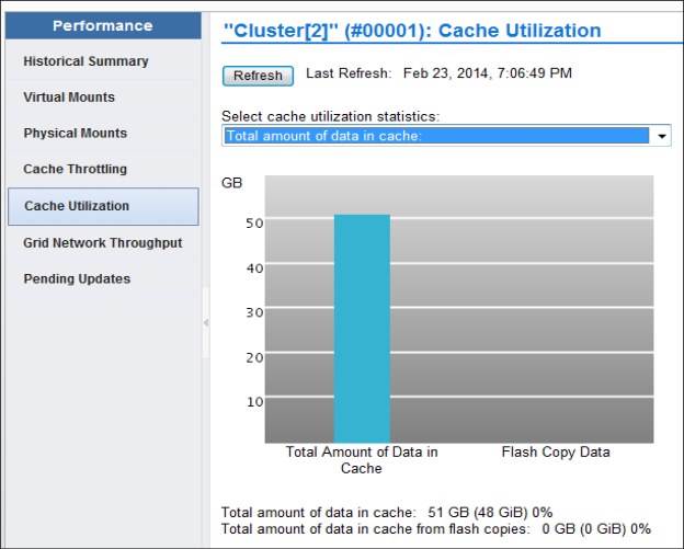
Figure 13-5 Cache usage of FlashCopy data
Also, you can control the usage of your virtual drives. You can select these displays on the MI:
•Virtual
•Virtual Tape Drives
Figure 13-6 is an example of virtual tape drive output.
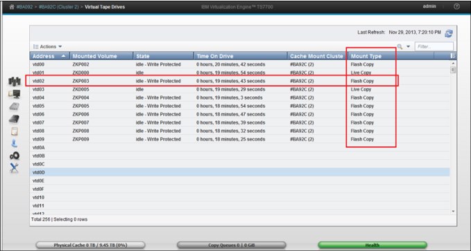
Figure 13-6 Virtual Tape Drive window during a FlashCopy for disaster recovery test
Considerations
DR tests have the following restrictions:
•Data is not automatically removed from a TS7760 or TS7720 if the Flash is enabled.
•Do not perform the DR testing by using the FlashCopy function when a cluster in the grid is unavailable. An attempt to enable a FlashCopy in this situation results in a failure. You can perform the DR testing by using the FlashCopy function if all clusters in the grid are powered on (they can be in service/offline state).
•To perform the FlashCopy function, all clusters in a grid must be reachable through the grid links. Otherwise, host console commands to enable write protect mode or FlashCopy fail with an internal error.
13.5 DR testing methods examples
Each method that is described in the following sections can be used as a step-by-step guide to running a DR test in a TS7700 grid environment. While it might be tempting to skip right to these lists, we advise that you review this chapter in its entirety before DR testing to ensure that you are familiar with the concepts and options available for DR testing in a TS7700 grid environment.
All of these methods have their advantages and disadvantages, so it is important that before you decide which method to use, that you weigh the advantages and disadvantages of each method against your environment and resources and then choose which method best fits your DR testing needs and ability.
|
Note: Each method assumes an independent DR site (DR host and at least one DR cluster). That is, it is assumed that no production hosts have had any devices online to the disaster clusters to read/write production data on those clusters.
|
13.5.1 Method 1: DR Testing using FlashCopy
The first method that you can choose to simulate a real disaster in your TS7700 grid uses FlashCopy on your disaster clusters.
The next section describes the steps that can be used to run DR testing using the FlashCopy functionality. For a detailed description of all commands, see IBM Virtualization Engine TS7700 Series Best Practices - FlashCopy for Disaster Recovery Testing, which is available at the Techdocs website (search for the term TS7700):
These steps were written in a checklist format to provide a reference of the steps that are needed to accomplish this method. It is advised that you review all of these steps before an actual DR exercise, and during the DR exercise. Because the steps were written to apply to more than one TS7700 grid configuration, make sure that before running each step that you understand each step and how it applies to your environment.
Method 1: DR Testing using FlashCopy: Steps
To perform DR using FlashCopy, complete these steps:
1. Determine which MEDIA1, MEDIA2, ERROR, and PRIVATE categories will be used by the DR host during the DR test. These categories must be unique from any category that is used by a production system to ensure separation of production volumes from DR (disaster) volumes.
2. Using the TS7700 MI, add the MEDIA1 and MEDIA2 categories that are chosen to the TS7700. This is done by selecting Virtual → Categories → Add Scratch Category.
3. Using the TS7700 MI, add the four new categories that are defined to the Exclude from Write Protect list in each cluster that is in the DR Family by selecting Settings → Cluster Settings → Write Protect Mode → Category Write Protect Properties → Add.
If exclusion category counts are limited, MEDIA2 and PRIVATE are the most important to define. ERROR only needs to be added to allow a volume to be moved out of an ERROR state. MEDIA1 is only needed if MEDIA1 is used or any ACS (Automatic Class Selection) routine can result in using a default Data Class in which MEDIA1 is included (even if not used).
4. Issue the following command to determine the current status of the DR configuration within the TS7700 grid:
LI REQ, <COMPOSITE>,DRSETUP, SHOW
If there is already a DR Family that is defined, you must choose to either use it or delete it and start with a new configuration. To delete it, you must remove each cluster (remove a TS7760 or TS7720 cluster last) and when the last cluster has been removed, the DR Family will be automatically deleted. The following command can be used to remove a cluster:
LI REQ, <COMPOSITE>,DRSETUP, <FAMILYNAME>, REMOVE, <CLUSTER ID>
Wait for the command response that confirms that the cluster was removed before continuing. After the last cluster has been removed, the command response confirms that the DR Family was deleted because no members exist.
The steps that follow assume that you do not have a DR Family defined.
5. Create the DR Family that will be used for the DR test and add a cluster to the DR Family. If the DR Family will be composed of multiple clusters, add the TS7760/TS7720 first. This is done using the following command:
LI REQ, <COMPOSITE>,DRSETUP, <FAMILYNAME>, ADD, <CLUSTER ID>
Wait for the command response confirming that the DR Family was created and the cluster was added before continuing.
6. After the DR Family has been created, this command can be used repeatedly to add additional clusters to the DR Family.
7. Enable Write Protect Mode for the clusters in the DR Family by issuing the following command:
LI REQ, <COMPOSITE>,DRSETUP, <FAMILYNAME>, WP,ENABLE
Wait for the command response confirming that write protect has been enabled successfully.
8. Verify that Write Protect Mode is active for the clusters in the DR Family by issuing the following command:
LI REQ, <COMPOSITE>,DRSETUP, SHOW, <FAMILYNAME>
The above steps can often be completed in advance of a DR test. In fact, they can be set up once and left enabled indefinitely. If done far in advance, the only item to consider is that the Write Protect Mode would need to be disabled in the DR Family clusters in the event of a true DR event as part of the DR sequence.
9. Choose the volume serial ranges that will be created and used for input/output processing on the DR host. These are known as DR volumes. Update the TMS on the production hosts to ignore the ranges during host cartridge entry processing.
10. On each DR cluster, ensure that the Management Classes that will be used by the DR volumes on the DR hosts do not make copies to other clusters in the grid when the DR volumes are written to. If wanted, define a new Management Class on the DR clusters to be used explicitly for DR testing. On each DR cluster, set the ‘Copy Mode’ for the Management Class used to ‘No Copy’ for each non-DR cluster by clicking Constructs → Management Classes.
11. IPL the DR host and restore the DR environment from the production environment.
12. Using the unique categories that are chosen in Step 1, define these MEDIA1, MEDIA2, ERROR and PRIVATE categories in the DEVSUPxx member on the DR host. These categories will be used by volumes created for use by the DR host during the DR test. After the categories are defined, IPL the DR host to ensure that the categories are used. Alternatively, the DS QL,CATS command can be used to dynamically set the categories without an IPL. If this alternative is used, be sure to update the DEVSUPxx as well with the new categories so that the categories will continue to be used if an IPL occurs.
13. If Livecopy usage is wanted, enable Livecopy by using the following command:
LI REQ, <COMPOSITE>,DRSETUP, <FAMILYNAME>, LIVECOPY,FAMILY
Wait for the command response confirming that the live copy usage is set to ‘Family’.
14. Verify that the DR Family environment is as expected by using the following command:
LI REQ, <COMPOSITE>,DRSETUP, SHOW, <FAMILYNAME>
15. Update the TMS on the DR host to enable the new volume serial ranges to be accepted during host cartridge entry processing.
16. If a new Management Class was defined for each DR cluster in Step 10, modify the ACS routines on the DR host to direct new tape allocations to this Management Class. Activate the new SMS configuration on the DR host.
17. On the DR host, vary online the devices to the DR Family clusters that are either TS7760 or TS7720. DO NOT vary online devices in any TS7740 clusters.
18. Using the TS7700 MI, insert the new volume serial ranges by selecting Virtual → Virtual Volumes → Insert a new virtual volume range. Verify that the DR Host has successfully processed the volumes during host cartridge entry by reviewing the SYSLOG for the CBR3610I messages surfacing those volumes.
19. Change the Autoremoval Temporary Threshold on the TS7760/TS7720 used for DR testing to ensure that enough cache space is available for DR data and production data. This is only applicable for CP0 and only if more than 10 TB is available in CP0. Wait until the removal process completes.
20. When you are ready to start the DR test, enable the FlashCopy using the following command:
LI REQ, <COMPOSITE>,DRSETUP, <FAMILYNAME>, FLASH,ENABLE
Wait for the command response confirming that the FlashCopy has been enabled successfully.
21. Verify that the DR Family environment is as expected by using the following command:
LI REQ, <COMPOSITE>,DRSETUP, SHOW, <FAMILYNAME>
22. Run the DR test.
23. When the DR test is complete, SCRATCH the volumes that were written to by the DR host. Be careful not to scratch production volumes. This can be done by using one of the following methods:
– Run a TMS job on the DR host that scratches the volumes that are written to by the DR host (volumes that are converted from SCRATCH to PRIVATE during the DR test). The job must only include volumes that were inserted on the DR host (surfaced earlier in the CBR3610I messages).
– Use ISMF to ALTER those volumes written to by the DR host to SCRATCH.
– Use the CBRSPLCS SAMPLIB member to change the use attribute of each volume to SCRATCH
24. After all of the volumes that are processed by cartridge entry on the DR host are in SCRATCH status, they can be deleted from the TS7700 by using host EJECT processing. This can be done by using one of the following methods:
– Run a TMS job to issue the EJECTs for these volumes.
– Use ISMF to EJECT each volume.
– Use the CBRSPLCS SAMPLIB member to eject each volume.
25. Shut down the DR host.
26. If the Management Class used on the DR cluster from Step 10 existed before the DR test and the 'Copy Mode' was updated for the DR test, change the ‘Copy Mode’ back to what it was before the DR test.
27. If you would like to keep the Write Protect Mode enabled and disable FlashCopy, use the following command:
LI REQ, <COMPOSITE>,DRSETUP, <FAMILYNAME>, FLASH,DISABLE
Wait for the command response confirming that the FlashCopy was deleted.
28. Alternatively, you can disable both Write Protect Mode and FlashCopy simultaneously by using the following command:
LI REQ, <COMPOSITE>,DRSETUP, <FAMILYNAME>, DOALL,DISABLE
Wait for the command response that confirms that the FlashCopy was deleted and write protect disabled.
29. Delete the DR Family. To delete it, you must remove each cluster (remove a TS7760 or TS7720 cluster last) and when the last cluster has been removed, the DR Family will be automatically deleted. The following command can be used to remove a cluster:
LI REQ, <COMPOSITE>,DRSETUP, <FAMILYNAME>, REMOVE, <CLUSTER ID>
Wait for the command response confirming that the cluster was removed before continuing. When the last cluster has been removed, the command response confirms that the DR Family was deleted because no members exist.
13.5.2 Method 2: Using Write Protect Mode on DR clusters
Another method that you can choose to use to simulate that of a real disaster is to use Write Protect Mode on your disaster clusters.
If you determine that FlashCopy for DR is not suitable to your DR environment, using the ‘Write Protect Mode on DR clusters’ method is the suggested alternative.
The following sections describe the steps that you can use to accomplish this method of DR testing. As with the previous method, these steps were written in a checklist format to provide a reference of the steps that are needed to accomplish this method. It is advised that you review all of these steps before an actual DR exercise, and during the DR exercise. Because the steps were written to apply to more than one TS7700 grid configuration, make sure that before running each step that you understand each step and how it applies to your environment.
Method 2: Using Write Protect Mode on DR clusters: Steps
To use Write Protect Mode on DR clusters, complete the following steps:
1. Determine which MEDIA1, MEDIA2, ERROR, and PRIVATE categories will be used by the DR host during the DR test. These categories must be unique from any category that is used by a production system to ensure separation of production volumes from disaster volumes.
2. Using the TS7700 MI, add the MEDIA1 and MEDIA2 categories that were chosen to the TS7700 by selecting Virtual → Categories → Add Scratch Category.
3. Using the TS7700 MI, add the four new categories that were defined to the Exclude from Write Protect list in each cluster that will be used as a DR cluster by selecting Settings → Cluster Settings → Write Protect Mode → Category Write Protect Properties → Add.
If exclusion category counts are limited, MEDIA2 and PRIVATE are the most important to define. ERROR only needs to be added to allow a volume to be moved out of an ERROR state. MEDIA1 is only needed if MEDIA1 is used or any ACS (Automatic Class Selection) routine can result in using a default Data Class in which MEDIA1 is included (even if not used).
4. Using the TS7700 MI, enable Write Protect Mode on each cluster that will be used as a DR cluster by selecting SETTINGS → Cluster Settings → Write Protect Mode → Enable Write Protect Mode → Submit Changes.
The previous steps can often be completed in advance of a DR test. In fact, they can be set up once and left enabled indefinitely. If done far in advance, the only item to consider is that the Write Protect Mode would need to be disabled in the DR clusters in the event of a true DR event as part of the DR sequence.
5. Choose the volume serial ranges that will be created and used for input/output processing on the DR host. Update the TMS on the production hosts to ignore the ranges during host cartridge entry processing.
6. On each DR cluster, ensure that the Management Classes that will be used by the DR volumes on the DR hosts do not make copies to other clusters in the grid when the DR volumes are written to. If wanted, define a new Management Class on the DR clusters to be used explicitly for DR testing. On each DR cluster, set the Copy Mode for the Management Class used to No Copy for each non-DR cluster by selecting Constructs → Management Classes.
7. Restart the DR host and restore the DR environment from the production environment.
8. Using the unique categories that were chosen in Step 1, define these MEDIA1, MEDIA2, ERROR, and PRIVATE categories in the DEVSUPxx member on the DR host. These categories will be used by volumes created for use by the DR host during the DR test. After the categories are defined, IPL the DR host to ensure that the categories are used. Alternatively, the DS QL,CATS command can be used to dynamically set the categories without an IPL. If this alternative is used, be sure to update the DEVSUPxx as well with the new categories so that the categories will continue to be used if an IPL occurs.
9. Update the TMS on the DR host to enable the new volume serial ranges to be accepted during host cartridge entry processing.
10. If a new Management Class was defined for each DR cluster in Step 6, modify the ACS routines on the DR host to direct new tape allocations to this Management Class. Activate the new SMS configuration on the DR host.
11. On the DR host, vary online the devices to the DR clusters.
12. Using the TS7700 MI, insert the new volume serial ranges by selecting Virtual → Virtual Volumes → Insert a new virtual volume range. Verify that the DR Host has successfully processed the volumes during cartridge entry by reviewing the SYSLOG for the CBR3610I messages surfacing those volumes.
13. Run the DR test.
14. When the DR test is complete, SCRATCH the volumes that were written to by the DR host. Be careful not to scratch production volumes. This can be done using one of the following methods:
a. Run a TMS job on the DR host that scratches the volumes that are written to by the DR host (volumes that are converted from SCRATCH to PRIVATE during the DR test). The job must include only volumes that were inserted on the DR host (surfaced earlier in the CBR3610I messages).
b. Use ISMF to ALTER those volumes written to by the DR host to SCRATCH.
c. Use the CBRSPLCS SAMPLIB member to change the use attribute of each volume to SCRATCH.
15. When all of the volumes that are processed by cartridge entry on the DR host are in SCRATCH status, they can be deleted from the TS7700 by using host EJECT processing. This can be done using one of the following methods:
– Run a TMS job to issue the EJECTs for these volumes.
– Use ISMF to EJECT each volume.
– Use the CBRSPLCS SAMPLIB member to eject each volume.
16. Shutdown the DR host.
17. If the Management Class used on the DR cluster from Step 6 existed before the DR test and the ‘Copy Mode’ was updated for the DR test, change the ‘Copy Mode’ back to what it was before the DR test.
18. If you would like to keep the Write Protect Mode enabled on the DR clusters, it is a good precaution to take to prevent accidentally returning production tapes to SCRATCH by the DR host.
19. Alternatively, you can disable Write Protect Mode in each DR cluster by using the TS7700 MI by selecting SETTINGS → Cluster Settings → Write Protect Mode → Disable Write Protect Mode → Submit Changes.
13.5.3 Method 3: DR Testing without Write Protect Mode
Another method that you can choose to use to simulate that of a real disaster is to run your DR test from a DR host that is attached to one or more disaster clusters while the production hosts continue to write data across the grid.
If your choice is between using Write Protect Mode and not using Write Protect Mode, it is recommended to use Write Protect Mode (Method 2), to provide an additional level of write-protection in case the TMS on the disaster host is not configured correctly to prevent writes to the production volumes.
Described in the following sections are the steps that you can use to accomplish this method of DR testing. As with the previous method, these steps were written in a checklist format to provide a reference of the steps that are needed to accomplish this method. It is advised that you review all of these steps before an actual DR exercise, and during the DR exercise. Because the steps were written to apply to more than one TS7700 grid configuration, make sure that before running each step that you understand each step and how it applies to your environment.
Method 3: DR testing without Write Protect Mode: Steps
To perform DR testing without Write Protect Mode, complete the following steps:
1. Determine which MEDIA1, MEDIA2, ERROR, and PRIVATE categories will be used by the DR host during the DR test. These categories must be unique from any category used by a production system to ensure separation of production volumes from disaster volumes.
2. Using the TS7700 MI, add the MEDIA1 and MEDIA2 categories chosen to the TS7700 by selecting Virtual → Categories → Add Scratch Category.
3. Choose the volume serial ranges that will be created and used for input/output processing on the DR host. Update the TMS on the production hosts to ignore the ranges during host cartridge entry processing.
4. On each DR cluster, ensure that the Management Classes that will be used by the DR volumes on the DR hosts do not make copies to other clusters in the grid when the DR volumes are written to. If wanted, define a new Management Class on the DR clusters to be used explicitly for DR testing. On each DR cluster, set the Copy Mode for the Management Class used to No Copy for each non-DR cluster by selecting Constructs → Management Classes.
5. Restart the DR host and restore the DR environment from the production environment.
6. Using the unique categories that were chosen in Step 1, define these MEDIA1, MEDIA2, ERROR, and PRIVATE categories in the DEVSUPxx member on the DR hosts. These categories will be used by volumes created for use by the DR host during the DR test.
After the categories are defined, Restart the DR host to ensure that the categories are used. Alternatively, the DS QL,CATS command can be used to dynamically set the categories without an IPL. If this alternative is used, be sure to update the DEVSUPxx as well with the new categories so that the categories will continue to be used if an IPL occurs.
7. Update the TMS on the DR host to enable the new volume serial ranges to be accepted during host cartridge entry processing.
8. Update the TMS on the DR host to reject any output that is directed towards volumes in the production volume serial range. This is done as a safeguard to protect against production tapes being accidentally written to by the DR host.
9. If a new Management Class was defined for each DR cluster in Step 4, modify the ACS routines on the DR host to direct new tape allocations to this Management Class. Activate the new SMS configuration on the DR host.
10. On the DR host, vary online the devices to the DR clusters.
11. Using the TS7700 MI, insert the new volume serial ranges by selecting Virtual → Virtual Volumes → Insert a new virtual volume range. Verify that the DR Host has processed the volumes during cartridge entry by reviewing the SYSLOG for the CBR3610I messages surfacing those volumes.
12. Mark all DFSMShsm ML2 volumes full by issuing the following command to DFSMShsm:
a. F xxxxx,DELVOL MIGRATION(MARKFULL).
b. Run the F xxxxx,HOLD RECYCLE command.
13. For maximum protection, ensure the following procedures do not run:
a. RMM housekeeping activity at the DR site
b. Short-on-scratch RMM procedures at the DR site
14. Run the DR test
15. When the DR test is complete, SCRATCH the volumes that were written to by the DR host. Be careful not to scratch production volumes. This process can be done using one of the following methods:
a. Run a TMS job on the DR host that scratches the volumes that are written to by the DR host (volumes that are converted from SCRATCH to PRIVATE during the DR test). The job must include only volumes that were inserted on the DR host (surfaced earlier in the CBR3610I messages).
b. Use ISMF to ALTER those volumes written to by the DR host to SCRATCH.
c. Use the CBRSPLCS SAMPLIB member to change the use attribute of each volume to SCRATCH.
16. After all the volumes that are processed by cartridge entry on the DR host are in SCRATCH status, they can be deleted from the TS7700 by using host EJECT processing. This process can be done by using one of the following methods:
a. Run a TMS job to issue the EJECTs for these volumes.
b. Use ISMF to EJECT each volume.
c. Use the CBRSPLCS SAMPLIB member to eject each volume.
17. Shutdown the DR host.
18. If the Management Class used on the DR cluster from Step 4 existed before the DR test, and the Copy Mode was updated for the DR test, change the Copy Mode back to what it was before the DR test.
13.5.4 Method 4: Breaking the grid link connections
The final method that will be discussed that you can choose to simulate that of a real disaster is to break the grid links between the production clusters and disaster clusters in a TS7700 grid.
The concern about losing data in a real disaster during a DR test is the major drawback to using this DR method. Because of this, if it is possible to use one of the DR methods described earlier (using FlashCopy or Write Protect Mode), it is suggested to use one of those methods.
|
Important: Do not use logical drives in the DR site from the production site.
|
Described below are the steps that you can use to accomplish this method of DR testing. As with the previous methods, these steps were written in a checklist format to provide a reference of the steps needed to accomplish this method. It is suggested that you review all of these steps before an actual DR exercise, and during the DR exercise. As the steps were written to apply to more than one TS7700 grid configuration, make sure that before running each step that you understand each step and how it applies to your environment.
Method 4: Breaking the grid link connections: Steps
To break the grid link connections, complete the following steps:
1. Determine which MEDIA1, MEDIA2, ERROR, and PRIVATE categories will be used by the DR host during the DR test. These categories must be unique from any category that is used by a production system to ensure separation of production volumes from disaster volumes.
2. Using the TS7700 MI, add the MEDIA1 and MEDIA2 categories that are chosen to the TS7700 by selecting Virtual → Categories → Add Scratch Category.
3. Choose the volume serial ranges that will be created and used for input/output processing on the DR host. Update the TMS on the production hosts to ignore the ranges during host cartridge entry processing.
4. On each DR cluster, ensure that the Management Classes that will be used by the DR volumes on the DR hosts do not make copies to other clusters in the grid when the DR volumes are written to. If wanted, define a new Management Class on the DR clusters to be used explicitly for DR testing. On each DR cluster, set the ‘Copy Mode’ for the Management Class used to ‘No Copy’ for each non-DR cluster by selecting Constructs → Management Classes.
5. Restart the DR host and restore the DR environment from the production environment.
6. Using the unique categories that were chosen in Step 1, define these MEDIA1, MEDIA2, ERROR, and PRIVATE categories in the DEVSUPxx member on the DR host. These categories will be used by volumes created for use by the DR host during the DR test. After the categories are defined, restart the DR host to ensure that the categories are used. Alternatively, the DS QL,CATS command can be used to dynamically set the categories without an IPL. If this alternative is used, be sure to update the DEVSUPxx as well with the new categories so that the categories will continue to be used if an IPL occurs.
7. Update the TMS on the DR host to enable the new volume serial ranges to be accepted during host cartridge entry processing.
8. Update the TMS on the DR host to reject any output that is directed towards volumes in the production volume serial range. This is done as a safe-guard to protect against production tapes being accidentally written to by the DR host.
9. If a new Management Class was defined for each DR cluster in Step 4, modify the ACS routines on the DR host to direct new tape allocations to this Management Class. Activate the new SMS configuration on the DR host.
10. On the DR host, vary online the devices to the DR clusters.
11. Using the TS7700 MI, insert the new volume serial ranges by selecting Virtual → Virtual Volumes → Insert a new virtual volume range. Verify that the DR Host has successfully processed the volumes during cartridge entry by reviewing the SYSLOG for the CBR3610I messages surfacing those volumes.
12. Engage your CE to break the grid link connections between the production clusters and the disaster clusters. As mentioned earlier, DO NOT disable a grid link with the Library Request command. Disabling the grid link with the command does not stop synchronous mode copies and the exchange of status information.
13. Use the TS7700 MI to enable read-only takeover mode on each disaster cluster to allow read-only access to volumes owned by each production cluster by selecting Service → Ownership Takeover Mode.
14. Mark all DFSMShsm ML2 volumes full by issuing the following command to DFSMShsm:
a. F xxxxx,DELVOL MIGRATION(MARKFULL).
b. Run the F xxxxx,HOLD RECYCLE command.
15. For maximum protection, ensure that the following procedures DO NOT run:
a. RMM housekeeping activity at the DR site
b. Short-on-scratch RMM procedures at the DR site
16. Run the DR test.
17. When the DR test is complete, SCRATCH the volumes that were written to by the DR host. Be careful not to scratch production volumes. Use one of the following methods:
a. Run a TMS job on the DR host that scratches the volumes that are written to by the DR host (volumes that are converted from SCRATCH to PRIVATE during the DR test). The job must include only volumes that were inserted on the DR host (surfaced earlier in the CBR3610I messages).
b. Use ISMF to ALTER those volumes written to by the DR host to SCRATCH.
c. Use the CBRSPLCS SAMPLIB member to change the use attribute of each volume to SCRATCH.
18. After all the volumes that are processed by cartridge entry on the DR host are in SCRATCH status, they can be deleted from the TS7700 by using host EJECT processing. This can be done using one of the following methods:
a. Run a TMS job to issue the EJECTs for these volumes.
b. Use ISMF to EJECT each volume.
c. Use the CBRSPLCS SAMPLIB member to eject each volume.
19. Shut down the DR host.
20. If the Management Class used on the DR cluster from Step 4 existed before the DR test and the Copy Mode was updated for the DR test, change the Copy Mode back to what it was before the DR test.
21. Use the TS7700 MI to disable read-only takeover mode on each disaster cluster. This returns each disaster cluster to its normal state regarding takeover processing. Disable read/write takeover mode on the production clusters as well by using Service → Ownership Takeover Mode.
22. Engage your CE to re-establish the link connection between the production clusters and the disaster clusters.
13.6 Expected failures during a DR test
Several expected failures that can occur during a DR test are described in this section.
The messages that are shown in Example 13-10 might appear if you try to read a logical volume that was not present at time zero in the DR Family.
Example 13-10 Expected failures during the disaster recovery test
IEF233A M 2500,A08759,,DENEKA1,STEP1,DENEKA.HG.TEST1.DUMP1
CBR4195I LACS retry possible for job DENEKA1: 399
IEE763I NAME= CBRLLACS CODE= 140394
CBR4000I LACS WAIT permanent error for drive 2500.
CBR4171I Mount failed. LVOL=A08759, LIB=HYDRAG, PVOL=??????,RSN=22
The message that is shown in Example 13-11 might also appear if you want to modify a volume that is in a write protect media category.
Example 13-11 Error message for volume in a write media category
IEF116I DENEKY6 STEP1 - MOUNT OF VOLUME PRIVAT ON DEVICE 2580 FAILED
IEE763I NAME= CBRLLACS CODE= 14017E
CBR4000I LACS MOUNT permanent error for drive 2580.
CBR4126I Library HYDRAG drive is in read only mode.
IEF272I DENEKY6 STEP1 - STEP WAS NOT run
The message that is shown in Example 13-12 might occur if a job was running on the cluster while the FlashCopy was enabled.
Example 13-12 Message for job running on the cluster while FlashCopy was enabled
IEF233A M 2507,A10088,,DENEKA8,STEP2,DENEKA.HG.TEST1.DUMP1
IEC518I SOFTWARE ERRSTAT: WRITPROT 2507,A10088,SL,DENEKA8,STEP2
IEC502E RK 2507,A10088,SL,DENEKA8,STEP2
IEC147I 613-24,IFG0194F,DENEKA8,STEP2,AUS1,2507,,DENEKA.HG.TEST1.DUMP1
..................Content has been hidden....................
You can't read the all page of ebook, please click here login for view all page.