
Chapter 7
Microfluidic Components, Devices and Integrated Lab-on-a-Chip Systems
Chapter Contents
7.1 Application Fields
7.2 Microfluidic Components
7.2.1 Passive Microvalves
7.2.2 Active Microvalves
Valving by Micromechanical Actuation
7.3 Controlled Transport by Diffusion
7.4 Integration for Microfluidic Transport, Sensing and Dispensing
7.5 Lab-on-a-Chip
7.5.1 Miniaturized Particle and Cell Sorting Devices
7.5.2 Cell Cultures and Fermentation Processes on Chip
7.6 Device-to-World Connections: The MATAS Concept
7.7 From the Lab Bench to Industry: Microchip Capillary Electrophoresis
7.7.1 Is There a Need for a Microfluidic-Integrated System at the Doctor’s Surgery
7.7.2 The Technology Behind the Lithium Case
7.7.3 Microchip Capillary Electrophoresis Instrumentation
7.7.4 Sample to Chip Interface
7.7.5 Samples
7.7.6 Results and Conclusions from the LICETAS Project
7.8 Conclusions
Defining the fabrication techniques and required features for mini-, micro- and nanofluidic devices, and clarifying their possibilities and drawbacks is becoming an important field of research and development. This chapter will summarize trends in microfluidic developments, and discuss microfluidic devices that will produce statistically meaningful results in chemical synthesis, chemical and pharmaceutical analysis, and biomedical diagnostics. It will also present a variety of systems that utilize the microfluidic-inside approach.
It is hoped that a layout database for miniaturized, fluidic sub-functional components, e.g., valves, pumps etc., will be established for the design of such systems allowing standardization of certain formats for pressurized inlets, seals, filling procedures and waste disposal, and enabling fast and effective communication with advanced microfabrication facilities for manufacturing on demand. This sort of database would allow chips to be customized during method development, and would speed up the engineering process from idea to product. Currently, trial and error plays a huge role in the design of microfluidic chip layouts by laboratory guided conceptual studies at an early stage, and dictates the implementation costs of a product. Although a conceptual approach is very important for the discovery of new phenomena, it hampers their commercial development. In application-driven research, these assembled sub-functions would ideally be tested similar to the modeling of electronic circuitry (e.g., utilizing dedicated modeling software). Intelligent design software has already been developed to some extent (e.g., marketed by Coventor, IntelliSense, etc.), but it needs to be further established in the innovation front-end process, and it is at present far from a universal standard.
Research programs can already benefit from externally defined fabrication lines for various types of processes and their product catalogs. For example, molding masters are ordered externally and are then used in relatively simple in-house replication techniques. A variety of commonly explored chip designs can also be ordered off the shelf (e.g., a capillary electrophoresis chip). An understanding of the fundamentals of pumping, valving, mixing and flow-monitoring are of prime interest during mini-, micro-, and nanofluidic research activities. This enables living organisms and cellular cultures to be investigated efficiently, but also a more efficient chemical screening can take place in miniature reactor designs (high throughput). Today, in chemistry and chemical engineering sciences many novel analytical methods and microreaction schemes are being developed using the microfluidic platform approach. Such an approach is safe and minimizes the need for resources during the optimization phases of chemical reactions for industrial use. This chapter focuses on some examples of microfabrication in the emerging markets for microfluidic applications.
7.1 Application Fields
Massively parallel screening methods that apply combinatorial (bio)chemistry in robotic-assisted fluid handling systems is one approach to handling extremely small samples. Microarray technology in medical diagnostics is another example of the implementation of experimental screening, which benefits tremendously from microfabrication techniques originating from the microelectronics industry. Expanding capabilities in the life sciences, which studies biological material, however, requires new solutions for chip manufacture. A variety of miniaturized, liquid-handling devices employ the principle of standardized microtiter plate formats. The miniature reaction vials are organized as an x–y matrix, which allows fast scanning across each of the reaction chambers. Flow-through devices allow continuous analysis on chip applying, for example, capillary electrophoresis (CE), chromatography or non-destructive optical techniques, all of which are integrated into one hand-held measurement system.
Continuing innovations in genomics and in analytical technology, provide pharmaceutical manufacturing and biotechnology businesses, such as brewing or food, it is hoped that these developments will benefit from new microfluidic methods. The concept of carrying out chemistry in confinement can allow the rapid development of new drugs and pharmaceutical treatments, as well as green and healthy food products.
Many innovations in these fields can be traced back to a basic phenomenon in fluid dynamics: the surface tension of incompressible fluids. A pressure is required to drive liquid through a capillary (microfluidic channel). The understanding of how different forces inside of capillaries interact such that they can be used effectively to transport compounds in these novel systems is an important area of research. Here, we will consider some working principles from a practical point of view, with the intention of being able to adapt a variety of operations known at the macroscale: pumping, dispensing, mixing, quenching, etc. Microfluidics can also be operated in combination with array strategies for feeding different samples to the chip, e.g., coupled with a mass-spectrometer. Many established conferences and peer-reviewed journals (Analytical Chemistry, Electrophoresis, Sensors and Actuators, Journal of Microelectromechanical Systems, Transducers, μTAS) have turned their attention to cell manipulation and analysis within artificial microenvironments. These arrangements allow well-defined spatial resolution for the observation of biological processes inside and in the extracellular matrix of living cells.
(Bio)chemical processes are investigated as part of the in vitro and in vivo testing of pharmaceutics, using animal models and volunteer human subjects. Pharmaceuticals may behave differently in vivo to what may be expected from in vivo studies; drugs may be unexpected effective against other diseases but can also cause undesired side effects. Knowledge of the overall (complex) behavior of a (bio) pharmaceutically active substance is difficult to generalize and statistically significant amounts of data have to be collected. Despite all the technological know-how, the risk of mistreating an individual is still high. Drugs can cause the agent of a disease to mutate, or cause undesirable changes in human genes (phenotype). Genotype and phenotype testing have become available for the diagnosis and evaluation of HIV drug resistance, and, in theory, resistance assays can be used to determine which drugs will be effective against an individual’s strain of HIV, so that the appropriate treatment can be selected. There is still, however, much controversy about the accuracy of these diagnostic tools, and their usefulness as predictors of treatment success. Microfluidic-assisted systems for cell biology can help to elucidate these mechanisms.
Microfabricated devices can address cells, cell components and environmental features in the conglomerate of cultured and in vivo bio-environments, which will allow researchers to follow the dynamics of an individual cellular and molecular control mechanism in detail. This understanding of cell regulatory processes may be utilized to reconstruct even more complex bioprocesses including, for example, neuron circuitry, and bone and tissue repair mechanisms. These investigations may also identify an appropriate response to overcoming the risk of ill-treatment in case of pathogen mutation. Microfluidic devices can furthermore assist the biomedical sciences in general. This hypothesis concerns the controlled operation of moving, distributing and storing reagents and samples resulting in so-called cell culture chips with integrated analytical functions, e.g., utilizing the aforementioned integration concept of electrochemical and optical sensor technology. Miniaturized sensors are capable of interacting with cells at the same length scale, which may offer additional information.
The flow-through concept has several advantages over a batch-type approach, although both aim for high throughput solutions, massive parallelism and high reliability. Batch processes, using multiple pipettes, are prone to contamination, cross-interference, and are slower and less accurate in dynamic response when compared to the microfluidic approach, with its spatial discrete reaction and detection features. Additionally, titer plates are difficult to control due to evaporation, but if covered vials are used, fast robotic access will be limited. The polymerase chain reaction (PCR) “on chip” is a typical example of enhanced operation using a flow-through microfluidic device for finger-printing in cell biology. Microfluidics are also preferred for basic research in the life sciences, molecular diagnostics, pharmacogenomic profiling for personalized therapeutic planning, and the detection of food contaminants and bio-weapons. At present, titer plates not only serve as convenient sample or reagent storage trays, but additional functions are increasingly being integrated into the same platform. This will also allow rapid data correlation from 96 (384,.. etc.) analysis positions in a single run. The cavities of a titer plate can also serve as a reaction vessel or cell culture chamber, if they are nourished by a microfluidic network and allowing for cross-culture interactions. These advances in titer plate development, show the clear movement towards integrated microfluidics, which makes it a next logical step to pursue this trend and go for massively parallel flow-through microsystems for screening. Microfluidic on-chip processes are expected to improve the control of the reaction sites due to optimized heat and mass transfer. However, method development for Lab-on-a-Chip is still slow, and is particularly hampered by the high investment costs for customized chip technologies compared to the already well-established batch-based array-type assays in biology. Categorizing the various fluidic layouts into functional subunits, which can be assembled in a similar way to electronic design layout for standard components and better methods for in silico modeling, however, should make-up or this relatively slow progress in the near term future.
Advanced on-chip fluid electrokinetics will allow samples and other reagents to be prepared by more sensitive methods, and will also allow multiple measurements to be made from the same sample. Sample clean-up and enrichment prior to capillary electrophoresis has been studied earlier by conventional systems, for example, by Busher and co-workers [66]. These techniques, including selective extraction methods, are very suitable for microfabricated analytical systems, and it will be of great interest to develop integration strategies for microfluidics devices, often referred to in the MEMS community as micro-total analysis systems (μTAS), because of their original implementation as an analytical tool [1–3].
This chapter will consider the conceptual development of the lithium sensor as an example. I have been fascinated by the development of this device myself, probably to a greater extent than was strictly relevant. Innovation in industry is seeded by research projects. A good example of this is the LICETAS (Lithium Capillary Electrophoresis Total Analysis System), conducted in the BIOS-Lab-on-a-Chip group, headed by Prof. Dr. Ir. Albert van den Berg, at the University of Twente and financially supported by the Dutch Science and Technology Foundation (STW). Consideration of the LICETAS project may help us to answer an important question: How should governments and industry leaders make educated choices over which research should be funded, when all the suggested research projects are, of course, good ideas in the first place? LICETAS did not appear to be exceptional among the many excellent ideas presented by scientists, and was still some way from clinical application [4]. Recently the device has been further developed by Medimate BV, The Netherlands, and reported by Yager as a cutting-edge development for point-of-care diagnostics citing Floris et al. in LabChip [5, 6].
Clarifying the key differentiators versus the incremental progression of a scientific contribution may help in making educated decisions for funding research, either by government evaluators, or by industrial organizations looking for applications for their products. However, I can only let the section in this chapter speak for itself regarding whether the time and the money were well spent in turning the measurement of the conductivity of a liquid into a feasible concept for clinical point-of-care applications. In contrast to the many good books available in this field, I add my own personal experience of post-doctoral research. I hope to inspire readers to add their own knowledge to develop new micro- or nanofabricated products. Maybe there is no longer that much room at the bottom for miniaturization technology, however, focusing on the More than Moore principle in the applied sciences may successfully pave the way to an uncrowded business niche in industry [7, 8].
7.2 Microfluidic Components
Generally, it is possible to bring a sensor to the measurement point, and simply expose the sensor to the environment of the measurand, but often this is not considered to be a practical solution. Particularly if the sample to be measured is blood, an off-line measurement is the method of choice. Also for many chemical engineering systems the decoupling of sample and production lines is often preferred, because the sample is crude and contains many more compounds than just the measurand. The sample needs to be worked-up, and sample preparation methods are needed if a measurement is to be conducted without interference from other compounds. Microfluidic components, and in particular a microvalve, could optimize sample preparation techniques, particularly when very small sample volumes are available, only. We therefore need to understand the control of transport phenomena of minute amounts of fluids (gases or liquids) when they are confined and moving from place to place. The efficiency of this transport is a particular concern in microfluidic systems. Most of the strategies using a variety of pumping mechanisms are inefficient at the small scale. On the other hand, at the very small length scale nature provides us with the phenomenon of diffusion as an efficient means of transport. Nevertheless, microscale operations, pumps, valves and mixers are still important structural elements for many microdevice operations. For details of the theoretical background of fluid mechanics, the study of continuum fluid dynamics equations and the laminar fluid flow patterns in confined spaces is important. With respect to the latter, I would like to refer to the physico-chemical background literature. An initial starting point for advanced reading is the compilation of publications from 2006 in the special issue on “Lab on a Chip” in Nature [9].
Microfluidic systems may be designed using any materials available in the microfabrication tool box: semiconductor materials, glasses, quartz, plastics, ceramics and even metals. With respect to valving and pumping, dynamic structural control is important. Examples do exist that use chemical interference on the valving or pumping structure, e.g., applying pH-induced volumetric changes in the case of elements fabricated from porous hydrogel materials, but mechanically rigid, structural mechanisms are still preferred in valve and pump designs. This is probably because they have a faster reaction time and more accurate mechanical placement. Prior to studying microfluidics it is strongly advised that the reader gains an overview of basic fluid mechanics at the macro- and mesoscale.
This book will introduce examples of microfabricated components for fluid handling, and the handling of the solutes in those fluids at the microscale in the next subsection. Some examples of non-moving structural elements that explore diffusion phenomena are also discussed. I anticipate that once some examples of the need for fluidic devices at this scale are illustrated, then the advanced study of transport and interface phenomena becomes much more exciting, and this study of illustrated practical cases will stimulate their industrial applicability.
A very good overview of the trend in micropumps, microvalves and micromixers has been presented within the context of the development of polymerase chain reaction (PCR) chips by Zhang et al. [10]. Specifically with respect to microvalves, Oh and Ahn presented a review article in 2006 [11]. Two years earlier, Laser and Santiago presented a review on micropumps [12]. Recently, these reviews were followed by an overview on pneumatic and hydraulic microactuators by De Volder and Reynaerts [13]. The latter discuss the importance of early MEMS research and development to microfluidics applications and illustrate a variety of designs in a comprehensive overview. Readers with a larger appetite for the design and application of fluid microactuation will doubtless highly appreciate the guidance on pneumatic and hydraulic microactuators given by De Volder and Raynaerts’ review.
7.2.1 Passive Microvalves
Structures that regulate fluid transport inside the microfluidic network passively are structural elements that move by externally applied pressure and exert a force onto the mechanical element (spring-loaded diaphragm or cantilever-type structure). By means of this force the element that otherwise rests against the valve seal is lifted [14]. Obviously, these valves are of limited use in stand-alone miniaturized microfluidic applications, since a pressure must be applied that works against the pressure drop across the flow resistance of the flow conduit and the air pressure at the outlet. Based on this principle, it is obvious that strong external pumps are required for operation with these passive valves. One advantage of these structural elements is, however, that no energy is required when the valve is closed, which suggests a fail-safe operation.
As an alternative, two pressure-driven flows may be used in a splitter-type element, called a microfluidic flip-flop, that pushes the liquid stream to either one side or the other of the outlet channels, depending on a pressure pulse fed into the splitter by one of the symmetrically-shaped control ports. A pressure pulse in the side channel directs the liquid stream to the opposite wall, where it remains until the introduced gas has been vented, when a reverse pulse is applied. This type of set-up has been considered for microflow computing. Figure 7.1 gives schematics of these two passive structural valving elements. The microfluidic flip-flop may be operated in gradient mode with a sheath flow from the control ports for the generation of chemical dilution or washing steps on chip.
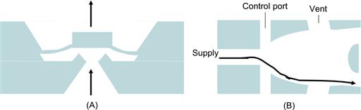
Figure 7.1 Passive microvalve structures. Diaphragm (A) in operating mode by increased inlet pressure. Microfluidic flip-flop structure (B) switching the flow direction between the two outlets by the pressure difference introduced by the normally symmetric control port flows.
Valving by the modification of material properties is also possible, for example, introducing a hydrophobic patch in a capillary can stop fluid transport. In this so-called stop valve the driving pressure must overcome the surface tension at the liquid meniscus. The threshold pressure depends on the hydrophobicity of the patch and its dimensions. In some Lab-on-a-Chip designs, a centrifugal force is applied to pass this type of barrier [15]. A similar effect may be obtained by an abrupt change in channel cross-section, which was demonstrated as one of the early, simple, valving principles in microfluidic devices [16].
7.2.2 Active Microvalves
Active microvalves operate normally “open”, and close in a defined manner by the displacement of a moving element that regulates the flow in a microchannel. Active microvalves are considered to be those valves that have moving parts, or have material properties that are actuated by an external source of energy, for example, electrical, thermal, etc. Microvalve designs based on phase-changes in materials have been demonstrated, as have relatively simple designs of so-called thermal-viscous valves, which integrate a heating element with an orifice-type structure. These principles are often preferred to the aforementioned passive microvalve designs. For industrial applications, however, one needs to address the promise-requirement cycle of a selected working mechanism for a microvalve incorporated into a Lab-on-a-Chip or microreactor design more carefully. Pumps and valves on a conventional scale may still be a better solution for many systems, and diaphragms and cantilever-type structural elements may be used to open or close the flow. The flow is either completely blocked, fully open or adapted by the remaining flow resistance of the valve. We described a set of microactuation principles in Chapter 5, which can also be applied to control microfluidic operations. A range of technical solutions have been presented in the scientific literature, or manufactured either at a research (functional demonstrator) or industrial scale (mass-manufactured devices). Due to their importance in microfluidic circuitry we will have a closer look at these structures in the following subsections.
Valving by Micromechanical Actuation
The micromechanical actuation of valves can be performed with the same microactuators as mechanical sensing applications, which we illustrated in Chapter 5. Combining the anisotropic etching of silicon and thin-film technology with electrical control circuitry and a means of a voltage applied to the actuator element; electrostatics will regulate the distance between the silicon boss structure and the microvalve seat. Adjusting the flow resistance at the valve orifice regulates subsequently the flow in the micro conduit. Figure 7.2 (left) depicts a schematic representation of this working mechanism. Alternatively, with the introduction of soft-MST utilizing PDMS a variety of interesting, pneumatically-actuated microfluidic valving structures can be made. An example is given by Cole et al. and is depicted at the right-hand side of Figure 7.2 [17]. Other actuator mechanisms, such as bimetallic, piezoelectric, or electromagnetic actuation can be coupled to diaphragm-type structures. Design modifications such as suspension bars can be included, which allow either to open up the flow through or in-plane of the wafer depending on the overall design of the microfluidic manifold in a specific application. Thermal expansion may be also used via changes of viscosity or temperature dependent phase-change materials. Gaseous compounds can be produced by electrochemical reactions in an enclosed reservoir and the increase in volume can be used to move a diaphragm. The latter mechanism was actually utilized in a design for an eye-pressure sensor.
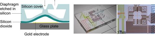
Figure 7.2 Micromechanical designs for valving. Left: schematic of an electrostatically actuated silicon valve enabled by anisotropic wet etching. Right: Optical micrographs depicting a PDMS-based microfluidic chip to generate and route droplets. The chip is fabricated by micromolding and lamination of two-layers of PDMS realizing multiplexed peristalic pumps for high-density integrated microfluidics.
Reproduced from reference [17].
Micromachined valves are also applied for the defined actuation of a Braille display, for example, utilizing specific conductive polymers in their designs [18]. A schematic design of a thermally actuated bimetallic microvalve is depicted in Figure 7.3. It was made by silicon etching, then a nickel structure was placed on top of the suspended silicon plate, by photolithography and electroplating. The thermally introduced mechanical stress in the bimetallic structure of approximately. 30 μm thick silicon and 30 μm thick nickel produces a defined stroke between the boss and the valve seat. Surface micromachining and special materials may also be employed for micropumps and valves, as in the dual valve design described by Chen et al. [19].
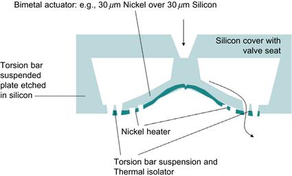
Figure 7.3 MEMS design for thermally actuated bimetal valve using electroplated Nickel as bimetal and heater. Schematic is based on silicon anisotropic etching as the principal microfabrication technology of the valve structure.
7.3 Controlled Transport by Diffusion
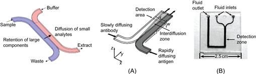
Controlling chemical operations in a microfluidic chip may be achieved solely by diffusion. The laminar flow regime supports the operation of two streams merging from two different inlet channels into one channel, while the flow remains discretely side-by-side inside of this one channel. Solutes from one stream can now enter the other, and in the interface chemical reactions may occur. This exchange of solutes may be utilized for gradient dosing or extraction purposes. The exchange between the two streams is entirely limited by diffusion. Figure 7.4 demonstrates a simple H- and T-shaped microfluidic layout which can be produced by microfabrication in glass, or special plastics supporting optical transparency, and thus visualization of the events occurring in the device. An even simpler version may be designed from wicking paper. This was recently highlighted as a potential ultra-low cost solution for global public health care by Whitesides and Yager [20, 21]. By means of these types of structures a variety of applications have been demonstrated, some of which have also been commercialized as single-use medical diagnostic devices such as, for example, the H-Filter® and T-sensor® Access™ cards offered by Micronics, Inc., USA [22].
7.4 Integration for Microfluidic Transport, Sensing and Dispensing
In standard (bio)chemical handling, fluids containing analytes or reagents are transferred by means of a pipette. This may be an automatic pipette, with multiple tips loaded/deloaded in parallel, but single-tip pipettes are still in use, particularly in research environments. Using microfluidic transport for a similar operation in an experimental set-up on chip requires some level of component integration. The capillary effect, related to the above mentioned surface tension of the fluid and the size of the microchannel, could also be used. Hereby important parameters are the filling length of the channel h against the ambient air pressure at the end of the capillary proportional to the surface tension γ, the specific weight of the fluid w, the angle between the edge of the free fluid surface θ and the channel wall, and the radius a of the capillary tube. This basic concept is cleverly exploited in the diffusional set-up given in Figure 7.4. To eventually allow the lock-in handling of liquid dispensing after loading, a diverse range of integrated devices have been designed and run in an automatic, or at least semi-automatic fashion. A pumping action can be produced by other means besides simply pressurizing the inlet of a channel through a piston-driven, syringe pump. The application of an electrical potential across the capillary length will also result in a pumping action. This technique applies a field of up to a few 100 V/cm and is called electroosmotic fluid flow. The method appears to be easy, but it still requires some effort to miniaturize all the components, particularly the high-voltage power supply.
Leak-tide integration of electrodes has also demanded the attention of manufacturers in the field. Micronit Microfluidics BV, Enschede, The Netherlands, for example, has tackled the challenges of robust, integrated manufacturing in glass, and today offers a range of standard and customized microfluidic glass chips. Figure 7.5 illustrates these examples of product implementation in this novel, life-science oriented, microfabrication service industry.
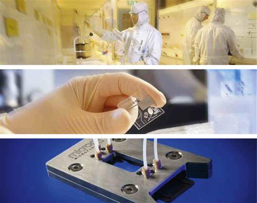
Figure 7.5 Product implementation from microfabrication to microchip testing by Micronit Microfluidics BV, Enschede, The Netherlands. Figures depict a view into Micronit’s cleanroom facility (top), an example of an integrated glass chip with electrical contacts (middle) and Micronit’s standardized chip holder for chip-to-world interfacing.
Image courtesy: Micronit Microfluidics BV, accessed online. [24].
7.5 Lab-on-a-Chip
The Lab-on-a-Chip originates from the initial development of miniaturized sensors and fluidic handling devices within one miniaturized package, the chip, so-called micro total analysis systems (μTAS) made up the first. A much broader implementation of these techniques quickly followed. There was considerable impetus for scientists already working on miniaturization to investigate means of measuring chemical reactions because of the large number of chemicals that are used in fabrication processes. While the latter not only attracted more and more scientists with a chemistry background to the research area of miniaturization technology, it also motivated the discovery of efficiency enhancement of chemical reactions performed in microfluidic channels.
Originally, Lab-on-a-Chip technology focused on analytical devices, and established such concepts as flow injection analysis (FIA) on chip. Throughout the last decade, however, we have experienced a revolution in this field in the life sciences. These have targeted a wide range of (bio)chemical reactions in cell cultures and clinical diagnostic point-of-care devices. The driver for this is the emergence of genetics as a medical field, where conventional analytical power is insufficient to sustain the required rate of experimental progress. So-called sample-in-answer-out capabilities are of considerable interest in life sciences [25–27].
Generally, micro- and nano-scale chemistry uses the increased surface-to-volume ratio resulting from the implementation of microfluidic devices. Combing μTAS and chemical synthesis research has led to the broader definition of this technical field, which is now known as Lab-on-a-Chip technology. The current prototypes translate the working principles of many standard laboratory analysis and synthesis techniques onto a chip card format (like a credit card). By fitting chemical reagents, test tubes, flasks and stirrers, pumps and valves onto a footprint hardly larger than a postage stamp has realized a paradigm shift in miniaturization. Figure 7.6 gives an introductory overview to the extensive developments of this novel field of technology.
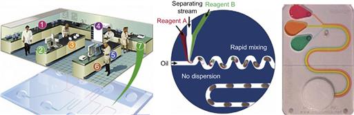
Figure 7.6 Laboratory processes on chip. Left: schematic illustration of translating key operations of conventional laboratories into chip formats. (Original source: Agilent, accessed online, 2005 [28].) Middle: a specific microfluidic set of operational steps on chip. (Reproduced from reference [29].) Right: an example of a commercial credit card-sized diagnostic device using a finger bellows that primes a wicking pad that then takes over the pumping action. (Reproduced by permission of The Royal Society of Chemistry [30].)
This on-going analytical revolution started with an extremely steep development curve in the 1980s, which approximately 30 years later, is reaching saturation of early curiosity-driven research. Although one cannot talk about a specific killer application this saturation clearly pays-off from a commercial point of view. The field of microfluidics controls the transport of gases and liquids inside the chip by a variety of structural components, as discussed in the previous section. Investigations of novel strategies for moving fluids in a channel network is described extensively in the literature. The initial developments in microfluidics were an off-spring of MEMS technology. These developments integrated valves and pumps for flow rate measurements, and mass sensors for highly defined gas supplies and safety equipment in the semiconductor industry. They also gave rise to pumps for controlled drug delivery for the chronically ill. Microfluidic circuits were also explored as far back as the 1970s in logic devices, because of their insensitivity to electromagnetic radiation.
Nowadays, microchemical reactions on a chip are popular as analytical systems for the same reasons as in analytical chemistry, and they are therefore branded as their own branch of Lab-on-Chip research and development, known as microreaction science and technology. Early on-line measurement systems were considered to be inferior to the possibilities of a well-equipped laboratory. Eventually, the introduction of flow-injection analysis, utilizing miniaturized systems was an economically driven choice. When it is more important in a bio(chemical) production line to have a rapid, crude measurement of product composition, miniaturization supported the rapid adoption of such μ-FIAs to be integrated into the production processes. The success of this supported the further validation of miniaturized sensor systems in field operations. This created a demand for the development of commercial microflow injection analysis (FIA) systems.
A FIA for (bio)chemical process lines is constructed as a mass flow controller for gases, in which a bypass line is utilized to carry out the measurement. One very successful example of chemical in-line measurement is the miniaturized gas chromatograph, marketed by Thermo-Fisher, who acquired the start-up company C2V BV. C2V developed this measurement system from concept to volume manufacturing.
Once the μ-FIA concept was introduced, researchers started to explore other application fields and to translate the micro total analysis approach to a variety of measurement challenges, including biology. The idea that biology could benefit from a system-in-a-card format is not all that obvious, since very sophisticated cell handling instrumentations already existed. Nevertheless, chips were introduced and tested, promoting the concept of automating cell manipulations at the level of a single cell. Microfluidic chip systems may actually be used to manipulate many thousands of single cells in parallel by integrating the capturing, triggering and analysis functions all into one system. Consideration had to be taken of the relevance to biology of taking measurements at the level of just one cell, since studies at the level of a population are usually necessary. Specifically, chips were considered as a means of learning more about cells in suspensions. Initial chip layouts utilized microfabrication to demonstrate miniaturized bio-handling systems similar to the operations that would normally be performed in an established fluorescent-activated cell sorter (FACS). FACS scanning the individual properties of the cells that previously had the opportunity for cell–cell interaction within the tissue population is a powerful tool for deriving statistically meaningful bio-information. Established non-chip formats allow a large number of cells to be counted by appearance (scatter, fluorescence from marker uptake, etc.), but without the possibility of tracing an individual cell in time throughout the experiment. If the single cell approach on chip is relevant biologically speaking then this design may be supported. However, the design of experiment with single cells remains a matter of further debate. The fact that in-vitro cultures of certain cell lines, in which cells are also isolated from their natural environment, are also a popular tool in biological experiments suggests that information collected from population, single-cell or tissue level can only model the in-vivo situation up to a certain level, and all the findings together may not produce a full understanding of real-life systems. We will not debate the various models for bio-medical experiments here, but will introduce the lab-on-a-chip concept and its technological realization by microfabrication as a potential approach for biological studies. Figure 7.7 shows the first microchip-based cytometer fabricated and tested by Micronics [31]. It clearly has been a milestone in the development of microfluidics for cell research.
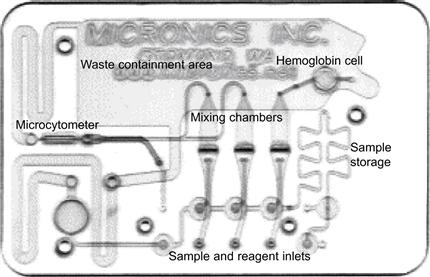
Figure 7.7 Micronics disposables are typically credit-card-sized, and most structural elements on these cards have dimensions ranging from about 100 μm to a few millimeters, use a low-cost rapid prototyping process that allows the design and testing of new microfluidic structures in 24 h or less.
Reproduced from reference [32].
The following subsections present an overview of microfluidics devices for particle and cell sorting, and miniaturized cell culturing systems, with a variety of integrated functionality. Micronics microfluidic card technology is based on laser micromachining, or stamping of foils and subsequent assembly by lamination.
7.5.1 Miniaturized Particle and Cell Sorting Devices
Medical research and diagnostics depend on the careful identification of dysfunctional tissue or blood patterns. Conventional fluorescent-activated cell sorters (FACS) are used in clinical medicine, and basic biological and material sciences to isolate mutated cell types from healthy ones. A mutated cell type is then cultured, and undergoes multiple pathogen testing. To simplify such cell sorting procedures, miniaturized cell sorting and culturing devices have been demonstrated by Wolff et al. [33]. Current microfluidic device philosophy is particularly focused on finding strategies for cell sorting and trapping, and the subsequent manipulation and analysis of one cell at a time. Greater automation, and thus a faster turnaround is expected. Although the methods and protocols discussed above are clearly important for innovative approaches in the market, they will not necessarily mediate faster discovery. Improved medical treatments or insights into physiological parameters will not be possible without the careful observation of the cell in its natural context, i.e., together with neighboring cells and the extracellular matrix.
7.5.2 Cell Cultures and Fermentation Processes on Chip
Industrial bioreactors are macro environments where the culturing of a specific cell type is performed. Lab-on-a-Chip concepts are considered for yield-enhancing optimization studies of small-scale fermentation processes and for giving better control of the fermentation process. Investigations of optimized bioreaction processes within miniaturized cell reactors were introduced approximately 10 years ago [34].
7.6 Device-to-World Connections: The MATAS Concept
In Chapter 6 we discussed a set of sensors used in microfluidic devices. Microfluidics applications aim for hybrid integration in a similar way to the concept of combining different micromechanical and electronics sensors into one measurement system. The implementation of different devices and components into one platform is often referred to as the Lab-on-a-Chip concept, illustrated in Figure 7.6. Today, such systems have found their way from universities into chemical analysis, separation technology and synthesis (microreaction technology). The health-care market demands faster and faster response on differentiating disease patterns, and therefore a biolab infrastructure now demands much more flexible processes and rapid updates of protocols for faster screening.
Although conventional mechatronic robotics still competes with the revolutionizing possibilities of microfluidics, the latter is now widely recognized in the life sciences and industrial (fine-chemical) process control markets. The benefits of miniaturization in fluid handling environments are the reduced consumption of reagents, shorter temperature cycling times, faster mixing and a high degree of automation. These factors can result in a higher throughput, and a reduction in costs compared to conventional methods. One unique technology that is suitable to deliver a flexible and cost-effective realization of a Lab-on-a-Chip system is the MATAS (Modular Assembly for (micro) Total Analysis Systems), produced by LioniX BV, Enschede, The Netherlands [35].
MATAS is a highly standardized, modular technology for the design and fabrication of Lab-on-a-Chip systems-in-a-package. The technology enables the hybrid integration of microfluidic components, micro-optical devices and control electronics into one platform. This modular microfluidics kit has been selected for on-line measurement of pH and conductivity, and merges precision engineering with silicon micromachining. Figure 7.8 shows different components and devices of the MATAS.
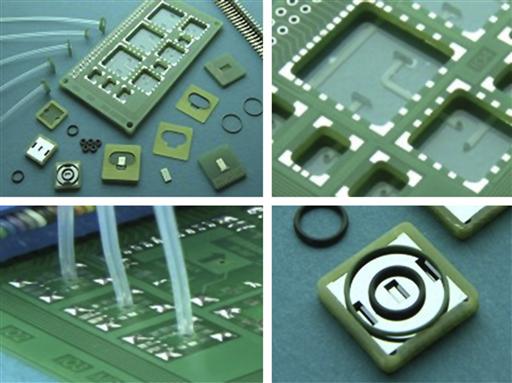
Figure 7.8 Different views of the components of the MATAS. The modular assembly PCB platform and components (top, left), detail of electronic interconnections (top, right), fluidic tubing (bottom, left) and silicon etched optical detection cell (bottom, right). MATAS may be utilized as a (micro-) Total Analysis and/or Lab-on-a-Chip system-in-a-package.
Image courtesy: LioniX BV [35].
Systems made up of these types of modules have so far been used as microreactors, sensors for pH, conductivity and ion concentrations, CE-chips, electrodes, flow sensors, micropumps, optical detectors, filters, valves and pressure sensors. All these different modules can be tested individually and exchanged just as quickly as ICs and resistors on a printed circuit board (PCB). The MATAS concept, originally developed by University of Twente’s spin-off 3T, of which the microfluidic division was acquired by LioniX, allows the user to integrate hybrids of different components into one customized package. Modules can include optics-based sensors, actuators and microelectronics which are already manufactured in large-scale production lines, as well as structures produced by speciality foundries. Figure 7.9 depicts a fully assembled μTAS for the detection of pH and ammonia.
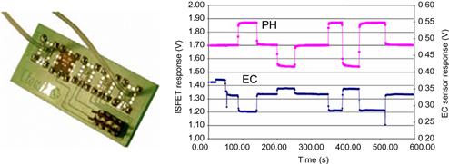
Figure 7.9 MATAS (left) for hybrid-integrated μTAS applications, here, ammonia detection. The traces (right) illustrate the measurement of pH and concentration changes in the analyte by integrated electrochemical sensor technology.
Image courtesy: LioniX BV, The Netherlands [35].
7.7 From the Lab Bench to Industry: Microchip Capillary Electrophoresis
Capillary electrophoresis (CE) is a well established separation method in analytical chemistry. At the conventional scale small bore tubes must be used, in order to quickly dissipate the heat that is generated by the current flowing through the capillary at the applied high electrical field strength (several tens of V/cm). Under these conditions, the ions within the sample will separate, since they diffuse at different rates within the analytical medium. The separation length of a conventional system is approximately one meter because conventional fluid handling systems cannot produce the tightly defined picoliter-sized plugs that microfluidic-implemented systems can. Figure 7.10 depicts an example of a conventionally operated CE system, together with a chip-based CE apparatus with a total foot-print of a desktop computer, as developed by Shimadzu.
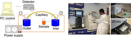
Figure 7.10 Left: schematic representation of the components of a conventional capillary electrophoresis (CE) set-up. Middle: established laboratory practice Beckman-CE work place for (bio)analytical chemistry. (Image accessed online, kindly provided by Dr. Stuart Le Grice, HIV Drug Resistance Program, National Cancer Institute-Frederick [36]). Right: desktop-integrated microchip CE system with optical UV-detection.
Image courtesy: E.X. Vrouwe, University of Twente, 2004.
I was involved in LICETAS, a governmentally funded project, from 2001 to 2005 as a post-doctoral researcher together with an analytical chemist, Elwin Vrouwe, who at the time was working for his PhD. Dr. Vrouwe currently works as an industrial researcher at Micronit Microfluidics BV and I decided to continue my academic career at University of Twente. Nevertheless, I believe, it may be valuable to discuss some aspects of my involvement with the early efforts of the LICETAS innovation track in the context of this book. The project demonstrates an example of how a small seed-project of 25,000.00 Euros, granted for knowledge transfer to a spin-off company may make all the difference to industrial success.
LICETAS uses microchip electrophoresis with an integrated conductivity sensor, for the measurement of lithium in blood from a finger stick sample. This brings us to the set of subsections that describe the implementation of microfluidics devices at the point-of-care (PoC).
7.7.1 Is There a Need for a Microfluidic-Integrated System at the Doctor’s Surgery?
Miniaturization technology is now capable of producing advanced analytical instrumentation that will fit within the palm of your hand. An answer to the above question may be: if technical progress has been made in this field, such that it may save a human life, we must therefore make every effort to explore its true potential. Once more we have to realize that it is the costs of implementation, and not the lack of good ideas or technical skills that delays the development chain from lab-bench to industry. As an example, the society’s investment into the LICETAS research project and its initial utilization path was, roughly speaking, 500,000.00 Euros, which mainly paid the salaries of the researchers working on the project over a period of approximately 5 years (PhD candidate 4 years, postdoctorate 2 years, entrepreneur ca. 1 year). In society the following scenario exists: For one patient, who has to travel to a doctor’s surgery, to get a blood sample measured by the centralized laboratory, the standard cost to the health-care provider is approximately 10 Euros per test. We can calculate that if this patient needs 10 tests per year, then the direct cost is just the 100 Euros per year, which will not justify the need for a microfluidic-integrated system at the doctor’s surgery. However, the indirect costs involved in the whole procedure are enormous and their reduction will have also a significant positive impact on society as a whole and improve the care of the individual patient.
Although better health care is the primary driver of innovation, it is the economics that will determine whether or not these innovations are implemented. It is therefore important to analyze the business case, and carefully consider the indirect costs involved in the procedure of reading a patient’s lithium level. Let us assume the following: 0.5 day traveling (home–lab–home), which means that the patient cannot work for at least half a day. With an average salary, this amount sums up to approximately 250 Euros (includes overhead for covering the time by a different member of staff). The patient may also need public transport or a taxi, at an average return ticket of 20 Euros. The total indirect costs for 10 tests per year therefore becomes 2700 Euros per patient per year.
In the Netherlands alone there are approximately 16,000 lithium cases. If we assume that we can halve the patient’s traveling time (because in 5 of the 10 tests the patient will measure the lithum level at home or at work with the LICETAS), a total of 21.6 million Euros could be saved. Of course, this is just a rough business plan, and the development costs of the device also need to be covered, but surely this sum justifies the original 0.5 million Euros spent on the research project. So there is indeed a need for a point-of-care lithium measurement system, although not necessarily in the surgery, but in the palm of the patient’s hand. Obviously, the full balance sheet of a company and a health-care provision facility are much more complex than the above example, but such simple financial overviews may give some guidelines on the decision-making process for the investment of public money.
7.7.2 The Technology Behind the Lithium Case
Lithium is a drug for the treatment of disordered brain functions. A psychiatrist needs to know the patient’s metabolic profile on lithium turnover to decide on the appropriate dose. Ideally, measurements are performed at, or at least prior to visiting the doctor’s surgery. This process may use a sample drawn from a finger stick only, or may need a whole blood sample taken from a venipuncture. Lithium is one of the most important mood stabilizers for treating bipolar mood disorders [37, 38], but one of its disadvantages is its narrow therapeutic range (0.4–1.2 mmol/L), which necessitates regular monitoring [39]. In the initial phase of the treatment the patient’s lithium level is measured once or twice a week. Once the concentration has stabilized, the testing interval can be reduced to once every couple of months. Standard lithium monitoring has some limitations. Typically the samples are obtained from a venipuncture, which can be unpleasant for the patient. The whole procedure, including obtaining a sample, transporting it to the laboratory, sample pretreatment and the actual analysis, can take up to 45 minutes. Also, fluctuations in the lithium level remain undetected because of the low frequency of testing. In countries where there are few facilities where lithium can be determined, the lack of equipment or trained personnel may limit its prescription. A point-of-care test for lithium can solve all of these issues, offering enhanced treatment of patients. Nowadays the plasma or serum lithium level is often determined with ion-selective electrodes (ISEs) [40], which are also used in point-of-care tests to determine a range of parameters, including potassium and sodium from approximately 65 μl of whole blood [41]. However, a test for lithium using ISEs was not commercially available until 2004 [42]. This test measures the change in light absorbance by a porphyrin compound as it forms a complex with lithium. The sample is applied onto a cell separator strip, which is subsequently transferred to a cuvette filled with the reagent. These manual handling steps can make the test vulnerable to errors. Also, a considerable volume – 50 μl – is required for the test.
By contrast, a separation method such as capillary electrophoresis (CE) is not limited to a single analyte. Conventional CE is used for a wide range of substances, including lithium, serum proteins, amphetamines, β-agonists, organic acids and other substances [43–48]. Miniaturization offers the possibility of developing point-of-care tests. Not only is microchip CE faster than conventional systems, but integration of on-chip sample preparation can offer point-of-care testing [49, 50]. Microchip CE of inorganic ions, including lithium, in aqueous samples is relatively well established [51–55], but there is little information on handling and transfer of small sample volumes onto the chip.
The analysis of finger stick samples would be a great improvement over venous whole blood, and microneedles, which pierce the skin without inflicting pain, would be even more interesting [56, 57]. The latter have been used, for example, to sample interstitial fluid from the skin for glucose measurement [58]. In principle, these needles can be integrated relatively easily into microfabricated devices such as microchip CE, although the microchip needs to be optimized to work with the sample volumes, which are typically in the order of a few nanoliters. Initial results are promising, but so far only qualitative analysis of whole blood has been demonstrated [59].
Reverse iontophoresis offers an alternative method for painless sampling, and this method has also been used to extract lithium from the skin [60]. However, the analysis still has to be performed in the laboratory, and it can take up to an hour and a half to collect enough lithium for an accurate analysis. When immediate results are not required, reverse iontophoresis could be an interesting alternative to finger stick measurements as it has been demonstrated for the GlucoWatch® biographer. This commercially developed ultra-minimally invasive glucose monitor is based on a selective amperometric biosensor [61]. In the LICETAS project, both venous and finger stick samples were used to prove the principle of microchip analysis of lithium [62–64]. The aim was to transfer sample volumes of less than 10 μl to the chip by a disposable sample collection device, similar to a microneedle array. However, to reach this stage, a sample loading protocol and an analytical method had to be established. The CE separation conditions were optimized by enabling the direct analysis of samples by using on-chip conductivity detection. The results of this project demonstrated that a hand-held lithium point-of-care analyzer instrument had considerable potential. The following subsection will discuss different aspects of this novel point-of-care technology, which is currently being developed commercially by the University of Twente’s MESA+ Institute for Nanotechnology spin-off, Medimate BV, Enschede, The Netherlands.
7.7.3 Microchip Capillary Electrophoresis Instrumentation
A computer-controlled, high voltage power supply, with four independently adjustable outputs was used to carry out microchip capillary electrophoresis measurements (CU 411, IBIS Technologies, Hengelo, The Netherlands). The power supply system also provided electrical current read out. A custom-made and commercially available conductivity detector was used for conductivity sensing, (Sprenkels Consultancy, Lelystad, The Netherlands). The detector signal was recorded with a data acquisition card (DAQCard 6036E, National Instruments, Austin, TX, USA), and an in-house written software package was used to control the power supply, and acquire and process the data, which included signal filtering and peak area calculations. Figure 7.11 depicts an overview of the components of the chip-holder, and also shows diagrams of the assembled microchip CE set-up, including the design. An image of a disposable blood-sample cup fitting the holder used in these experiments is also included in the figure.
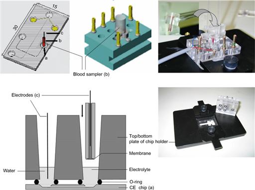
Figure 7.11 Top (from left to right): illustration of chip-layout (filled-grey circles indicate the contact pads of the integrated thin film electrodes at the end of the microchannel) and positioning of the blood sampler. Diagram of the chip holder top plate with the inserted blood sampler. Upper right corner: photograph of the assembled chip holder with an inset (upper left corner in the photograph) showing a close-up of the disposable and blood-filled sampler prior to insertion into the holder (transfer process marked with an arrow in the photograph). Bottom left: schematic of a cross-section view of the assembled chip/chip holder. Bottom right: de-assembled chip holder with a glass chip (30 mm × 15 mm) inside of the bottom plate.
Image courtesy: E.X. Vrouwe, University of Twente, 2005.
7.7.4 Sample to Chip Interface
For the initial experiments, a glass capillary was used as a sample collector. Glass disposable micropipettes (0.5 mm inner diameter, 1.0 mm outer diameter, Drummond Scientific Company, Broomall, USA) were cut to a length of 1 cm. One end was sealed with a filter membrane (Millipore, mixed cellulose esters, 0.22 μm pore size) by heating the capillary in a gas flame and pressing it onto the membrane. The internal volume of the capillary, which defines the minimum amount of sample required, is 2.0 μl. A specific sample collector principle is tested for analysis of whole blood, by using a finger stick sample from a healthy volunteer. Capillary action draws the sample into the center channel, and up to the filter membrane, which, together with a water plug in the chip compartment, creates the sampling interface. Observation of the chip through a microscope shows that the cells do not go through the filter. The chip therefore stays clean, and can be used for multiple samples during initial reliability testing. This simple and easy to use sample collector helped to manage the experimental budget, because we could reuse the chip in pre-clinical trials of the system [64]. For subsequent testing, a disposable blood sample-cup could be used.
7.7.5 Samples
Five serum samples were received from the Medisch Spectrum Twente Hospital Group, Enschede, The Netherlands. The samples were obtained from venipunctures of patients undergoing lithium therapy. The lithium concentrations were first determined in the hospital with an ion selective electrode (Cobas Integra 800, Roche, Basel, Switzerland). The lithium level was in the range of 0.49 to 0.90 mmol/L for all samples. The samples were subsequently analyzed by microchip CE on the same day. Additional samples were prepared as follows: whole blood was directly drawn into a sample collector after performing a finger stick on healthy volunteers, using disposable 21 gauge lancets with a puncture depth of 1.8 mm (Haemolance, HaeMedic AB, Munka Ljungby, Sweden). These samples did not contain any lithium, and therefore a second sample was collected in a sample vial by pipetting from the finger stick of the healthy volunteer, and spiked with 2 mmol/L lithium. Finally, a heparinized plasma sample was kindly provided by the Medisch Spectrum Twente Hospital Group from a patient on lithium therapy. This sample contained a lithium concentration of 0.62 mmol/L, as determined by the hospital.
7.7.6 Results and Conclusions from the LICETAS Project
A microchip assembly with a glass capillary interface as blood collector was successfully used for proof-of-prinicple in the laboratory to determine lithium in a whole blood sample from a healthy volunteer. A calibration sample is run first, followed by a whole blood sample from a healthy volunteer. Figure 7.12b shows the electropherogram containing sodium and magnesium in the typical ratio for whole blood. For quantitative measurements we used the lithium-spiked blood sample, as well as a heparinized patient plasma sample of known concentration. Both these samples were pipetted into a sample collector for transfer to the chip. Figure 7.12c and d show the electropherograms of these two samples, respectively. The lithium peaks can be clearly identified from these data. The lithium concentration of the patient plasma sample was determined at 0.7 mmol/L (7% RSD, n = 3) using the calibration sample in Figure 7.12a, which is in good agreement with the hospital value of 0.62 mmol/L.
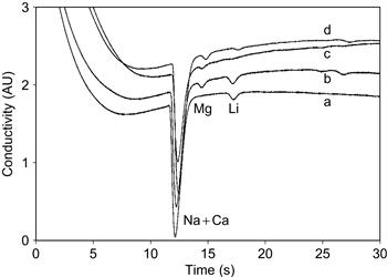
Figure 7.12 Electropherograms of (a) aqueous calibration mixture with 140 mM Na and 2 mM Li, (b) citrated whole blood spiked with 2 mmol/L Li, (c) whole blood without anticoagulant and (d) heparinized plasma from a patient on lithium therapy. Sampling via glass capillary. BGE 30 mmol/L ammonium acetate/acetic acid.
Image courtesy: E.X. Vrouwe, University of Twente, 2005
Figure 7.13 depicts correlation between the lithium determined by the CE microchip and an ion selective electrode at the hospital over five samples. Each point is the average of 6 measurements for the microchip system.
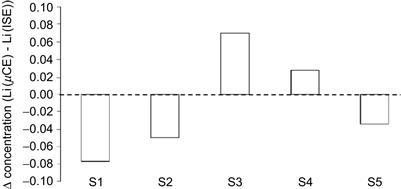
Figure 7.13 Comparison of the standard clinical values received by automated ion selective electrode (ISE) measurement with the values achieved by microchip CE method (μCE). Five patient blood samples (S1–S5) were tested. Bar diagram shows the difference of the two measurement values, which is within 10% of the clinical value.
The microchip CE device is a versatile method for analyzing whole blood. Separations of sodium, magnesium, calcium and lithium are performed in less than 20 seconds without any off-system sample pretreatment. The disposable sample collectors presented here offer a convenient method for transferring a finger stick sample to the chip, and also serve to filter out potentially interfering blood cells. The chip itself does not come into direct contact with the sample, and can be used repeatedly for method validation. The sample stacking using a water plug worked reliably for three consecutive runs. Using sodium as an internal standard, clinically relevant lithium levels have been determined in serum samples, and the measurements are consistent with ion selective electrode results. The relatively high detection limit of 0.15 mmol/L and low precision need further optimization. This preliminary proof-of-principle gave an appropriate insight into the potential of this technique, and the results of this study were the first landmarks of the subsequent path for valorization, which has been initiated by the researchers on the governmentally funded project.
The knowledge gained through this project was successfully transferred from the University of Twenty’s MESA+ Institute for Nanotechnology to its spin-off company Medimate BV. Based on additional seed-money from the Valorisation Program of the Dutch Science and Technology Foundation (STW), Mediate was able to take its first steps in using the scientific results, and translating the original concepts of the experimental set-up and the chip into a multi-reader version of a unique new product: a point-of-care solution for lithium measurements by the patient themselves. The product consists of a stand-alone reader (no external computer is required) and single-use sample cassettes with the chip. Both these units are depicted in Figure 7.14.
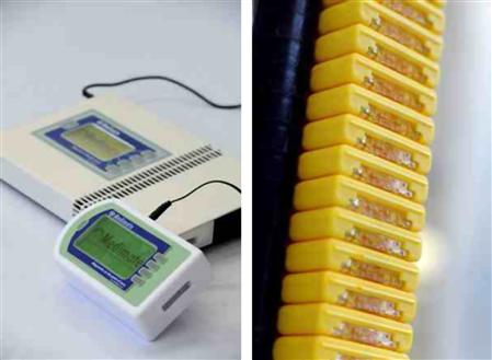
Figure 7.14 Multireader (left) and sample cassettes showing the mounted single-use chip for microchip capillary electrophoresis developed and manufactured by Medimate BV.
Image courtesy: Medimate BV [65].
7.8 Conclusions
Original studies of the etching of micromechanical diaphragms for pressure sensors led first to the development of micromechanical actuators, and then to microvalves and pumps in microfluidics. Understanding diffusion and other transport phenomena, of course, is as important in confined environments as understanding the mechanics of pumping. The accurate fabrication of microfluidic channels in glass has opened up the possibility of studying micro- and nanofluidic behavior by advanced optical microscopy. Fluorescence and absorbance methods have been developed to determine the type and concentration of compounds in chemical mixtures. This plethora of novel opportunities has allowed the study of chemical reactions in-situ as well as the manipulation of delicate proteins or cells. Research on the optimization of soft-matter handling protocols is on-going in the field of Lab-on-a-Chip technology.
Studying and utilizing microfluidics has given rise to new applications. Although the microfluidic service industry is already well established, its full potential has yet to be explored. Possible avenues include chip layout services, provision of accessories and chip manufacture on demand. In this chapter, we discussed the potential for a lithium point-of-care microchip device. Estimation of the potential of these types of developments is not easy, and proof-of-principle studies (feasibility) can help to reduce the economic risks. Standards for this type of measurement protocol are yet to be formulated, so patenting is not a real indicator that the solution has an industrial applicability. However, it is applicability that is demanded by the European patent law actually for a patent to be granted. LICETAS was at a very early stage of development when it was transferred to a spin-off company, however, know-how was all the young start-up needed.
Work at the research stage showed the lithium peak appearing within the electropherogram drawn from a blood plasma sample as early as 2002; the method was not validated for its accuracy in a clinical setting. The results therefore were of generic interest to the scientific community, but not of importance to the medical diagnostics market because of the lack of a proof-of-concept for quantitative validation of the method. As soon as the quantitative reliability of the method could be demonstrated, the process of technology transfer to a company made sense. In due course, the required multidisciplinary know-how was collected by the newly formed spin-off company and turned into a novel product with an appropriate patent portfolio to commercially back-up the company’s innovative technology.
Early stage technology transfer is a highly feasible approach to bring innovative solutions from the university to the market, but the LICETAS project operated at an extremely high risk to avoid its results being shelved as soon as the PhD thesis had been defended successfully. The fact that this did not happen was probably based on the right people being present in the right location, at the right time within one dedicated project team, and an appropriate funding agent (the Dutch Science and Technology Foundation, STW) sharing the one vision of bringing technical sciences to the marketplace.
REFERENCES
1. Blom N, Fettinger JC, Koch J, Ldi H, Manz A, Widmer HM. Implementing chemical sensors in industry: Novel approaches. Sens Actuators B Chem. 1991;5(1–4):75–78.
2. Freaney R, McShane A, Keaveny TV, et al. Novel instrumentation for real-time monitoring using miniaturized flow systems with integrated biosensors. Ann Clin Biochem. 1997;34(3):291–302.
3. Kopp MU, Crabtree HJ, Manz A. Developments in technology and applications of microsystems. Curr Opin Chem Biol. 1997;1(3):410–419.
4. Wilding P, Verpoorte S, Allen Northrup M, Yager P, Quake S, Landers J. Microtechnology in the clinical laboratory: Will it solve analytical problems, and when will it make an impact?. Clin Chem. 2010;56(4):508–514.
5. Yager P. Cutting edge: A prefilled, ready-to-use electrophoresis based lab-on-a-chip device for monitoring lithium in blood. Lab Chip Miniaturisation Chem Biol. 2010;10 1757–1757.
6. Floris A, Staal S, Lenk S, et al. A prefilled, ready-to-use electrophoresis based lab-on-a-chip device for monitoring lithium in blood. Lab Chip Miniaturisation Chem Biol. 2010;10(14):1799–1806.
7. Chakrabarty K. Digital microfluidic biochips: A vision for functional diversity and more than Moore. In: 2010;3–4. Proceedings IEEE Annual Symposium on VLSI ISVLSI 2010.
8. Wise KD. Microelectronics in the “More than Moore” era. In: 2010;3–4. Device Research Conference, Conference Digest DRC.
9. Hogan J. Lab on a chip: A little goes a long way. Nature. 2006;442:351–352.
10. Zhang C, Xing D, Li Y. Micropumps, microvalves, and micromixers within PCR microfluidic chips: Advances and trends. Biotechnol Adv. 2007;25(5):483–514.
11. Oh KW, Ahn CH. A review of microvalves. J Micromech Microeng. 2006;16. doi 10.1088/0960-1317/16/SR01.
12. Laser DJ, Santiago JG. A review of micropumps. J.Micromech Microeng. 2004;14. doi 10.1088/0960-1317/14/6/R01.
13. De Volder M, Reynaerts D. Pneumatic and hydraulic microactuators: A review. J Micromech Microeng. 2010;20. doi 10.1088/0960-1317/17/7/00.
14. Bien DCS, Mitchell SJN, Gamble HS. Fabrication and characterization of a micromachined passive valve. J Micromech Microeng. 2003;13(5):557–562.
15. Madou M, Zoval J, Jia G, Kido H, Kim J, Kim N. Lab on a CD. Annu Rev Biomed Eng. 2006;8:601–628.
16. Man PF, Mastrangelo CH, Burns MA, Burke DT. Microfabricated capillary-driven stop valve and sample injector. In: United States: Univ of Michigan, Ann Arbor; 1998;45–50. Proceedings of the IEEE Micro Electro Mechanical Systems (MEMS).
17. Cole MC, Desai AV, Kenis PJA. Two-layer multiplexed peristaltic pumps for high-density integrated microfluidics. Sens Actuators B Chem. 2011;151(2):384–393.
18. Spinks GM, Wallace GG, Ding J, Zhou D, Xi B, Gillespie J. Ionic Liquids and Polypyrrole Helix Tubes: Bringing the Electronic Braille Screen Closer to Reality. Proceedings of SPIE – The International Society for Optical Engineering. 2003;5051:372–380.
19. Chen P-J, Rodger DC, Meng EM, Humayun MS, Tai Y-C. Surface-micromachined parylene dual valves for on-chip unpowered microflow regulation. J Microelectromech Syst. 2007;16(2):223–231.
20. Martinez AW, Phillips ST, Whitesides GM, Carrilho E. Diagnostics for the developing world: Microfluidic paper-based analytical devices. Anal Chem. 2010;82(1):3–10.
21. Osborn JL, Lutz B, Fu E, Kauffman P, Stevens DY, Yager P. Microfluidics without pumps: Reinventing the t-sensor and h-filter in paper networks. Lab Chip Miniaturisation Chem Biol. 2010;10(20):2659–2665.
22. Yager P, Edwards T, Fu E, et al. Microfluidic diagnostic technologies for global public health. Nature. 2006;442(7101):412–418.
23. Hatch A, Kamholz AE, Hawkins KR, et al. A rapid diffusion immunoassay in a t-sensor. Nat Biotechnol. 2001;19(5):461–465.
24. Micronit Microfluidics BV. www.micronit.com (accessed 12.04.11).
25. Easley CJ, Karlinsey JM, Bienvenue JM, et al. A fully integrated microfluidic genetic analysis system with sample-in-answer-out capability. Proc Natl Acad Sci. 2006;103(51):19272–19277 USA.
26. Blazej RG, Kumaresan P, Mathies RA. Microfabricated bioprocessor for integrated nanoliter-scale sanger DNA sequencing. Proc Natl Acad Sci. 2006;103(19):7240–7245 USA.
27. Hutchison III CA. DNA sequencing: Bench to bedside and beyond. Nucleic Acids Res. 2007;35(18):6227–6237.
28. Agilent Technologies. http://www.agilent.com (accessed 12.04.11).
29. Song H, Tice JD, Ismagilov RF. A microfluidic system for controlling reaction networks in time. Angew Chem Int Ed. 2003;42(7):768–772.
30. Weigl B, Domingo G, LaBarre P, Gerlach J. Towards non- and minimally instrumented, microfluidics-based diagnostic devices. Lab Chip Miniaturisation Chem Biol. 2008;8(12):1999–2014.
31. Micronics. http://www.micronics.net (accessed 12.04.11).
32. Weigl BH, Bardell RL, Cabrera CR. Lab-on-a-chip for drug development. Adv Drug Deliv Rev. 2003;55(3):349–377.
33. Wolff A, Perch-Nielsen IR, Larsen UD, et al. Integrating advanced functionality in a microfabricated high-throughput fluorescent-activated cell sorter. Lab Chip Miniaturisation Chem Biol. 2003;3(1):22–27.
34. Fitzgerald DA. Macro opportunities in microfluidics. Scientist. 2003;7.
35. LioniX microfluidics. www.lionixbv.com (accessed 12.04.11).
36. http://home.ncifcrf.gov/hivdrp/SLG_Fig11.jpg. http://home.ncifcrf.gov/hivdrp/SLG_Fig11.jpg; http://home.ncifcrf.gov/hivdrp/Le_Grice_lab.html, 2011 (accessed 12.04.11).
37. Birch NJ. Inorganic pharmacology of lithium. Chem Rev. 1999;99(9):2659–2682.
38. Müller-Oerlinghausen B, Berghöfer A, Bauer M. Bipolar disorder. The Lancet. 2002;359(9302):241–247.
39. Amdisen A. Monitoring of lithium treatment through determination of lithium concentration. Dan Med Bull. 1975;22(7):277–291.
40. Linko S. Automated ion-selective measurement of lithium in serum A practical approach to result-level verification in a two-way method validation. Accredit Qual Assur. 2001;6:31–36.
41. Erickson KA, Wilding P. Evaluation of a novel point-of-care system, the i-STAT portable clinical analyzer. Clin Chem. 1993;39(2):283–287.
42. Glazer WM, Sonnenberg JG, Reinstein MJ, Akers RF. A novel, point-of-care test for lithium levels: Description and reliability. J Clin Psychiatry. 2004;65(5):652–655.
43. Huang X, Gordon MJ, Zare RN. Quantitation of Li+ in serum by capillary zone electrophoresis with an on-column conductivity detector. J Chromatogr B Biomed Sci Appl. 1988;425(2):385–390.
44. Dolnik V. Capillary electrophoresis of proteins 2003–2005. Electrophoresis. 2006;27(1):126–141.
45. Boatto G, Faedda MV, Pau A, Asproni B, Menconi S, Cerri R. Determination of amphetamines in human whole blood by capillary electrophoresis with photodiode array detection. J Pharm Biomed Anal. 2002;29(6):1073–1080.
46. Zhou T, Hu Q, Yu H, Fang Y. Separation and determination of β-agonists in serum by capillary zone electrophoresis with amperometric detection. Anal Chim Acta. 2001;441(1):23–28.
47. Boden J, Bächmann K. Investigation of matrix effects in capillary zone electrophoresis. J Chromatogr A. 1996;734(2):319–330.
48. Jabeen R, Payne D, Wiktorowicz J, Mohammad A, Petersen J. Capillary electrophoresis and the clinical laboratory. Electrophoresis. 2006;27(12):2413–2438.
49. Cheng J, Kricka LJ, Scheldon EL, Wilding P. Sample preparation in microstructured devices. Top Curr Chem. 1998;194:215–231.
50. Cunningham DD. Fluidics and sample handling in clinical chemical analysis. Anal Chim Acta. 2001;429(1):1–18.
51. Guijt RM, Baltussen E, Van Steen GD, et al. Fabrication of quartz microchips with optical slit and development of a linear imaging UV detector for microchip electrophoresis systems. Electrophoresis. 2001;22(2):230–234.
52. Pumera M, Wang J, Opekar F, et al. Contactless conductivity detector for microchip capillary electrophoresis. Anal Chem. 2002;74(9):1968–1971.
53. Lichtenberg J, de Rooij NF, Verpoorte E. A microchip electrophoresis system with integrated in-plane electrodes for contactless conductivity detection. Electrophoresis. 2002;23(21):3769–3780.
54. Tanyanyiwa J, Abad-Villar EM, Fernndez-Abedul MT, et al. High-voltage contactless conductivity-detection for lab-on-chip devices using external electrodes on the holder. Analyst. 2003;128(8):1019–1022.
55. Berthold A, Laugere F, Schellevis H, et al. Fabrication of a glass-implemented microcapillary electrophoresis device with integrated contactless conductivity detection. Electrophoresis. 2002;23(20):3511–3519.
56. Reed ML, Lye W-K. Microsystems for drug and gene delivery. Proc IEEE. 2004;92(1):56–75.
57. Gardeniers HJGE, Luttge R, Berenschot EJW, et al. Silicon micromachined hollow microneedles for transdermal liquid transport. J Microelectromech Syst. 2003;12(6):855–862.
58. Mukerjee EV, Collins SD, Isseroff RR, Smith RL. Microneedle array for transdermal biological fluid extraction and in situ analysis. Sens Actuators A Phys. 2004;114(2–3):267–275.
59. Luttge R, Berenschot EJW, de Boer MJ, et al. Integrated lithographic molding for microneedle-based devices. J Microelectromech Syst. 2007;16(4):872–884.
60. Leboulanger B, Aubry J-M, Bondolfi G, Guy RH, Delgado-Charro MB. Lithium monitoring by reverse iontophoresis in vivo. Clin Chem. 2004;50(11):2091–2100.
61. Tierney MJ, Tamada JA, Potts RO, Jovanovic L, Garg S. Clinical evaluation of the glucowatch biographer: A continual, non-invasive glucose monitor for patients with diabetes. Biosens Bioelectron. 2001;16(9–12):621–629.
62. Vrouwe EX, Luttge R, van den Berg A. Direct measurement of lithium in whole blood using microchip capillary electrophoresis with integrated conductivity detection. Electrophoresis. 2004;25(10–11):1660–1667.
63. Vrouwe EX, Luttge R, Olthuis W, van den Berg A. Microchip analysis of lithium in blood using moving boundary electrophoresis and zone electrophoresis. Electrophoresis. 2005;26(15):3032–3042.
64. Vrouwe EX, Luttge R, Vermes I, Van Den Berg A. Microchip capillary electrophoresis for point-of-care analysis of lithium. Clin Chem. 2007;53(1):117–123.
65. Medimate Diagnostics. www.medimate.nl (accessed 12.04.11).
66. Busher BAP, Tjaden UR, van der Greef J. Three-compartment electrodialysis device for on-line sample clean-up and enrichment prior to capillary electrophoresis. Journal of Chromatography A. 1997;788:167–172.