
3D machining system for artistic wooden paint rollers
Abstract:
In this chapter, an intelligent machining system based on an NC machine tool with a rotary unit is introduced to efficiently and easily produce many kinds of artistically designed wooden paint rollers. A post-processor with the fuzzy feed rate generator is also presented to effectively make the machining system run. The post-processor allows the NC machine tool to easily transcribe a relief design from the surface on a flat model to the one on a cylindrical workpiece. The fuzzy feed rate generator generates suitable feed rate values according to the curvature of each relief design. Experimental results show that artistically designed wooden paint rollers can be successfully carved using the proposed machining system.
5.1 Background
Fukuoka prefecture is one of the largest furniture manufacturers in Japan. The interior city Ohkawa is located at the south part of Fukuoka. Although furniture is mainly made from various wooden materials, the production of furniture has been gradually decreased in two decades because of changes in consumer preference and industrial structure. As a result, other promising wooden products are currently being considered in order to efficiently use wood resources in Fukuoka. As one example, wooden paint rollers attract our attention. In the home-decorating industry, handheld paint rollers with a simple pattern are generally used to transcribe a design to a wall just after painting. Interior planners and decorators want to use more artistically designed paint rollers to cope with various user needs, but the pattern designs are limited to several common ones. In order to efficiently provide user-oriented roller designs, a new 3D design and machining system should be considered for limited production with a wide variety of wooden paint rollers. However, it is not easy to perform its elaborate carving even when the latest woodworking machinery is used, because wooden paint rollers have a cylindrical shape. In the furniture manufacturing industry, since three-axis NC machine tools and five-axis NC machine tools with a tilting head are generally used, a new machining system for wooden paint rollers should be designed, keeping the use of such conventional machine tools in order to save investment in equipment.
Five-axis NC machine tools have a major advantage over three-axis ones when machining a free-form surface efficiently. Up to now, 3D machining systems based on a five-axis NC machine tool have been actively developed and studied in various manufacturing industries. Takeuchi et al. [45,46] proposed a general method for generating NC data from the collision-free tool path of five-axis control machining centers. The post-processor they developed can convert CL data to actual NC data, taking account of the structure of machining centers, linearization, feed rate control and spindle rotation control. Xu et al. [47] presented a technique to avoid inefficient five-axis machining practices by automatically creating and verifying a feasible tool-path prior to the actual metal cutting. Chen et al. [48] developed a hybrid five-DOFs parallel kinematic machine tool constructed using the TRR-XY mechanism and its post-processing system. The effects of the cutter shapes and the machine construction on the post-processing were investigated. Lei et al. [49] developed a novel probe-ball measurement device which was designed to measure the overall position errors of a five-axis machine tool, and a method using double ballbar [50] was proposed to inspect the motion errors of the rotary axes out of five-axes. Furthermore, Cao et al. [51,52] proposed an offset approach of machining freeform surfaces using a five-axis NC machine tool with a cylindrical cutter or toroidal cutter, in which Archimedes’ helicoidal surface, pseudo-sphere and hyperbolic paraboloid surfaces were successfully machined.
When a five-axis NC machine tool with a tilting head, generally used in the furniture manufacturing industry, is applied to cylindrical machining or carving, a workpiece can not be made in a single pass, i.e. it needs to perform complicated repositionings several times as well as achieving a special jig. Such a five-axis NC machine tool does not seem to be successfully used for the manufacturing of wooden paint rollers with a relief design at present, due to the complexity of the process and the resulting workpiece setup time.
There are several research projects which tackle feed rate problems. For example, Timar et al. [53] developed an algorithm which computes the time-optimal feed rate variation along a curved path. Heo et al. [54] proposed a machining time estimation model using NC block distributions. An intelligent contour control strategy was investigated to improve the contour error of CNC machine tools by Tarng et al. [55], in which a cross-coupled fuzzy feed rate control scheme was presented to reduce the contour error. Zuperl et al. [56] discussed the application of a fuzzy adaptive control strategy to the problem of cutting force control in high-speed end-milling operations, in which it is designed to adaptively maximize the feed-rate subject to an allowable cutting force on the tool. Farouki et al. [57] reported variable feed rate CNC interpolators for constant material removal rates along Pythagorean hodograph (PH) curves. The proposed curvature-compensated feed rate scheme has important potential applications in ensuring part accuracy and in optimizing part programs consistent with a prescribed accuracy. Furthermore, a new class of machine codes for the specification of PH curve tool paths and associated feed rate functions was proposed in [58]. In that study, experimental results from an implementation of real-time PH curve interpolators on an open-architecture CNC milling machine are described. However, it is not easy for engineering users to apply such methods to conventional NC machine tools without using an open-architecture controller.
In addition to the above research, there are already in commercial use machines that incorporate nonlinear interpolation (e.g. the non-uniform rational B-spline curve interpolation known as the NURBS interpolation) into NC programs to improve overall machining. Optimization programs are available to automatically adjust the feed rate based on NURBS curves. However, it requires not only a special controller which can deal with NC program interpolated by an NURBS curve, but also a corresponding CAM system which can generate an NURBS code such as G06. From the viewpoint of equipment cost, it is also important to consider how to effectively utilize conventional machine tools in the manufacturing of wooden products.
Improvements to advanced cylindrical grinding machines have been also proposed. For example, Frank et al. [59] developed a CNC cylindrical grinding machine for non-circular workpieces. Although parts with circular and non-circular cross-sections could be completely machined in one operation, the performance on circular cross-sections with small edges was not mentioned. Therefore, the grinding machine would not be able to carve a wooden paint roller, the cylindrical surface of which has many small edges. Couey et al. [60] showed that force measurements were capable of providing useful feedback in precision grinding with excellent contact sensitivity, resolution, and detection of events occurring within a single revolution of the grinding wheel. Tawakoli et al. [61] developed a prototype internal grinding machine based on new kinematics. The target was to defeat some problems of internal grinding such as poor enrichment of coolant lubricant, deflection of grinding tool, and so on.
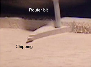
Summarizing the above, it can be seen that the easy suppression of undesirable edge chippings in machining cylindrical wooden workpieces with a relief design has not been discussed yet. In this chapter, a 3D design and machining system based on a three-axis NC machine tool with a rotary unit is introduced efficiently and at a low price to produce wooden paint rollers with an artistic design. A key point is to use common, conventional three-axis NC machine tools. In order to realize the machining system effectively, the following two points are considered in designing a corresponding post-processor. One is a basic function which efficiently generates suitable NC data to carve a relief design on a cylindrical wooden workpiece. The proposed postprocessor transforms a base tool path called cutter location data to NC data, mapping the y-directional pick feed to the rotational angle of the rotary unit [62]. The other is a systematic generation of feed rate values to suppress edge chippings on a relief design and to shorten the cycle time required for machining. Edge chipping is a particular problem when a wooden workpiece is machined by a router bit, because wooden workpieces are considerably more brittle than metallic materials. Edge chipping tends to appear with the increment of feed rate. Our proposed post-processor generates suitable feed rate values using a simple fuzzy reasoning method based on an operator’s experience and skill, while checking edges and curvatures calculated based on positions in CL data. The variation of curvature can be estimated by calculating the variation of the distance between two adjacent positions in CL data. The results of the experiment show that wooden paint rollers with an artistic relief design can be successfully carved without any chipping.
5.2 Conventional five-axis nc machine tool with a tilting head
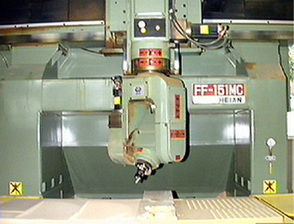
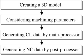
In this section, a 3D machining system based on a five-axis NC machine tool with a tilting head is evaluated as a conventional system [63]. The five-axis NC machine tool is one of the most representative and popular machine tools in wood product manufacturing. The machining system consists of a 3D CAD/CAM with variable axis function and a post-processor. Fig. 5.1 shows the five-axis NC machine tool (HEIAN FF-151MC). The NC machine tool has a tilting head that can be simultaneously inclined and rotated. It should be noted however that corrected NC data are required to run the NC machine tool as a computer simulation. The post process generally means to compute corrected NC data from CL data. Fig. 5.2 shows the general process to calculate the corrected NC data for the five-axis NC machine tool.
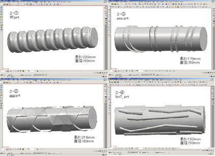
Examples of paint rollers with a relief design are shown in Fig. 5.3. We first draw the model of the relief design using a 3D CAD. Secondly, the CAM parameters such as pick feed, path pattern (e.g., zigzag path), in/out tolerances and so on are set according to the requirement of actual machining. The main-processor of the CAM calculates cutter paths using the parameters. The cutter paths are called CL data. The i-th step CL(i) in CL data is composed of position vector p(i) = [x(i) y(i) z(i)]T and normal direction vector n(i) = [vx(i) xy(i) vz(i)]T as written by
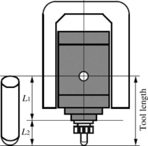
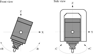
Finally, the post-processor generates the corrected NC data for the five-axis NC machine tool with a tilting head, by only considering a tool length [63]. Fig. 5.4 shows the tiltable main head which has a ball-end mill at the tip. The tool length L1+ L2 is defined as the distance from the center of swing to the tip of the end mill, which should be measured in advance. The post-processor transforms the CL data into NC data for five-axis NC machine tools as shown in Fig. 5.1. The main head can be inclined around y-axis and rotated around z-axis within the range ± 90 and ± 180 degrees, respectively. The inclined and rotated axes are called the fourth axis (B-axis) and fifth axis (C-axis), respectively. The i-th step in the corrected NC data is written by
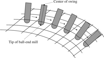
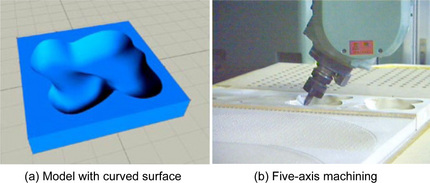
where b(i) and c(i) are the head angles of the inclination and rotation as shown in Fig. 5.5, respectively. The CL data generated from the main-processor of the CAM are composed of sequential points on the model surface as shown in Fig. 5.6. If the NC data are transformed from the CL data without considering the tool length and are given to the NC machine tool, then the center of swing is obliged to directly follow the NC data. As can be guessed, this would result in a serious and dangerous interference between the main head and the workpiece. However, if the center of swing follows the corrected NC data given by (Eq. 5.3) and (Eq. 5.4), the tip of the ball-end mill can desirably move along the model surface as shown in Fig. 5.6. Fig. 5.7 shows a designed model with a curved surface and the machining scene. It has been proved from the machining experiment that the proposed post-processor can generate suitable NC codes for the five-axis NC machine tool with a tilting head.
Recently, such a five-axis NC machine tool with a tilting head has become the subject of attention in wooden product manufacturing. However, it has been recognized from a machining experiment that the five-axis NC machine tool is not good at carving roller models, as shown in Fig. 5.3. Although its high machining performance is expected to exceed the capability of standard NC machine tools, it has hardly been used for carving roller models yet. The main reason is that the roller models as shown in Fig. 5.3 cannot be machined in a single path of the cutter, i.e. models must be machined using several paths of the cutter, requiring extensive cutter repositioning; thus the 3D machining of artistically designed paint rollers is complicated and time consuming. Furthermore, it is not easy to model a relief design on a cylindrical shape. To overcome these problems, a 3D machining system based on a three-axis NC machine tool with a rotary unit is introduced in the next section.
5.3 Intelligent machining system for artistic design of wooden paint rollers
As described in the previous section, wooden paint rollers have a cylindrical shape with an artistic design, so that it is not easy to achieve elaborate carving even when the latest woodworking machinery such as a five-axis NC machine tool with a tilting head is used. Generally, metallic cylindrical parts are precisely processed by an expensive CNC turning centre with milling capability. However, three-axis NC machine tools and five-axis NC machine tools with a tilting head have been widely used in the furniture manufacturing industry, and therefore it is necessary (when considering equipment cost) that new woodworking machinery for wooden paint rollers should be designed to utilize existing NC machine tools. In this section, a three-axis NC machine tool with a rotary unit and its post-processor are proposed to efficiently produce artistic wooden paint rollers of many kinds of designs. The proposed machining system is realized easily and at a low price only by adding a simple rotary unit to a conventional three-axis NC machine tool. The post-processor provides two effective functions. One is technique to transform CL data without feed rate values to NC data, mapping the y-directional pick feeds to rotational angles of the rotary unit. The post-processor allows a well-known three-axis NC machine tool to easily transcribe a relief design from the surface of a flat model to that of a cylindrical model. The other is an elaborate addition of feed rate values according to the curvature of each design to protect the cylindrical surface from undesirable edge chippings. The post-processor generates safe feed rate values by using a simple fuzzy reasoning method while checking edges and curvatures in a relief design, and appends them into NC data. The post-processed NC data act gently on the fragile edges of wooden paint rollers.
5.3.1 Post-processor for a three-axis NC machine tool with a rotary unit
Conventional paint rollers generally have no artistic designs at all, and the designs are limited to flat or simple patterns even if they have. As mentioned in the previous section, unfortunately, it is not easy to carve a relief design on a cylindrical model even if the five-axis NC machine tool with a tilting head is used. First of all, we discuss a problem concerning the 3D machining of wooden cylindrical shapes with a relief design. When the modeling of a roller is conducted using a 3D CAD, a base cylindrical shape is modeled in advance. Then a relief design is drawn on the cylindrical model. However, the modeling of the relief design on the cylindrical shape, as shown in Fig. 5.3, is a complicated task, even when 3D CAD software is used. Next, it is also not easy to realize 3D machining using the five-axis NC machine tool with a tilting head, in which the NC data generated from the CAM are composed of x-, y-, z-, b- and c- directional components. Thus, to easily provide many kinds of paint rollers with a wide variety and low volume to the home decorating industries, a machining system that can directly carve an artistic relief design on a cylindrical workpiece must be developed.
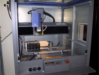
In this subsection, to solve these problems, a new 3D machining system is considered based on a three-axis NC machine tool with a rotary unit, and a post-processor is proposed for the rotary unit. The overview of the proposed machining scheme is illustrated in Fig. 5.8. The post-processor allows such conventional woodworking machinery as the three-axis NC machine tool to elaborately produce wooden paint rollers. An artistic design drawn on a flat model surface can be easily transcribed to a cylindrical model surface. In the remainder of this section, the system is described in detail. A three-axis NC machine tool with x-, y- and z-axes must be first prepared to realize the proposed concept. As an example, an NC machine tool MDX-650A provided by Roland D.G. as shown in Fig. 5.9 is used for experiments. The NC machine tool is equipped with an auto tool changer ZAT-650 and a rotary unit ZCL-650A. The mechanical resolution of the rotary unit is about 0.0027 degrees. The NC machine tool has four DOFs, i.e., three translations and one rotation. This subsection addresses how to easily make a wooden paint roller with an artistic relief design. The most important point is that proper NC data for the NC machine tool with a rotary unit can be generated in one step. To meet this aim, the post-processor generates the NC data which transcribe the design on a flat model to that on a cylindrical model. By applying the post-processed NC data, the NC machine tool can directly carve an artistic relief design on a cylindrical workpiece.
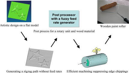
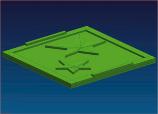
Next, we describe on the feature of the post-processor. A desired relief design is first modeled on a flat base model as shown in Fig. 5.10. CL data are secondly generated with a zigzag path as shown in Fig. 5.11. In this case, the coordinate system should be set so that the pick feed direction is parallel to the table slide direction of the NC machine tool, i.e y-direction. The proposed post-processor transforms the CL data without gFEDRAT/ h statements into the corresponding NC data, mapping the y-directional position to the rotational angle of the rotary unit. As can be seen from the components of the NC data, when the rotary unit is active, the table slide motion in y-direction is inactive. The post-processor first checks all steps in the CL data, and extracts the minimum value y_min and the maximum value y_max in y-direction. The angle a(i) for the rotary unit at the i-th step is calculated from
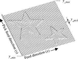
where y_length is the length in y-direction, which is easily obtained by y_max – y_min. The CL data p(i) = [x(i) y(i) z(i)]T at the i-th step is transformed into the NC data composed of [x(i) a(i) z(i)]T by using Eq. (5.5). The length in y-direction is transformed into the circumference of the roller model. It is expected that the relief design shown in Fig. 5.10 is desirably carved on the surface of a cylindrical workpiece. Thus, the proposed system provides a function that easily transcribes an artistic design from the surface on a flat model to that on a cylindrical wooden workpiece fixed to the rotary unit.
5.3.2 Feed rate generation using fuzzy reasoning
It is generally known that feed rate is one of the most important parameters to smoothly control NC machine tools and to reduce the total machining time. Wooden materials are essentially brittle in machining, so the regulation of feed rate is especially significant to protect the surface from an edge chipping as shown in Fig. 5.12. The key factors that affect the feed rate to be set are mainly the complexity of the relief design and the kind of wooden material. The feed rate must be adjusted not only to avoid the edge chipping on the cylindrical wooden workpiece, but also to shorten the machining time. When a common 3D CAD/CAM is used, the feed rate values are given with a gFEDRAT/ h statement in the CL data through the main process of CAM, and F-codes such as F3000.0 (i.e., 3000 mm/min.) corresponding to the feed rate values are written in NC data through post process. Thus, the feed rate value cannot be considered and generated in the post process, which is very inconvenient and a drawback for the case of using a common 3D CAD/CAM. Feed rates should be recalculated rapidly according to an actual machining situation. Also, if the cutter path has a large curvature or small edge then undesirable material chipping becomes easy to occur. This means that the machining accuracy tends to decrease, and therefore we cannot obtain a shape faithful to the model designed by 3D CAD. In particular, when a wooden paint roller with a relief design is machined, the problem of edge chipping cannot be avoided. Therefore, the feed rate should be slowed down suitably so that a small artistic design is not damaged by the edge chipping. Note, however, that conventional post-processors do not possess the function to systematically and elaborately decrease feed rate values according to linear interpolated positions given by gGOTO/ h statements in CL data. In other words, the operator must return to the main-process of CAM to correct the feed rate values.
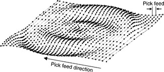
The proposed post-processor has a function that can automatically generate feed rate values, e.g. F1000.0, from CL data without using feed rate statements according to the curvature of each model, not only to stop edge chipping but also to shorten the machining time. When the postprocessor is used, the operator sets only two parameters, which are the minimum and maximum values of the feed rate. Of course, the post-processor is easily applied to NC machine tools that do not have an open-architecture controller. Generally, the main-processor of CAM calculates the CL data p(i) = [x(i) y(i) z(i)]T with a linear approximation so that a workpiece can be machined within the tolerance of a designed model. Therefore, the larger the curvature, the higher its point density. Accordingly, considering the curvature results in acquiring the distance d(i) = ||p(i + 1) — p(i)|| between two adjacent steps in CL data and its increment ∆d(i) = d(i + 1) — d(i). Fig. 5.13 shows an example for the relation between the distance and the point density with respect to CL data.
5.3.3 Fuzzy feed rate generator
In this section, we propose a fuzzy feed rate generator that generates suitable feed rate values according to d(i) and ∆d(i). The fuzzy feed rate generator consists of two simple fuzzy reasoning parts whose consequent parts have constant values. When the current position X(k) = [X(k) Y(k) Z(k)]T of the end mill at the discrete time k is X(k) ∈ [p(i), p(i + 1)], the fuzzy rules are described by
where ![]() and
and ![]() are the j-th antecedent fuzzy sets for two fuzzy inputs d(i) and Δd(i); cjA and cjB are the consequent constants at the j-th rule for the feed
are the j-th antecedent fuzzy sets for two fuzzy inputs d(i) and Δd(i); cjA and cjB are the consequent constants at the j-th rule for the feed ![]() and its compensation
and its compensation ![]() ; L is the total number of fuzzy rules. The confidence of each antecedent part at the j-th rule is obtained by
; L is the total number of fuzzy rules. The confidence of each antecedent part at the j-th rule is obtained by
where μX(![]() ) denotes the confidence of a fuzzy set labeled by X. Therefore, the fuzzy reasoning results for the feed rate F(i) and its compensation ∆ F(i) are respectively calculated by
) denotes the confidence of a fuzzy set labeled by X. Therefore, the fuzzy reasoning results for the feed rate F(i) and its compensation ∆ F(i) are respectively calculated by
The resultant fuzzy feed rate ![]() (i) is realized in the form
(i) is realized in the form
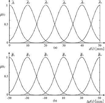
Note that the fuzzy set used is the following Gaussian membership function
where p is the center of membership function and q is the reciprocal value of standard deviation. Figures 5.14 (a) and (b) show the antecedent membership functions designed for d(i) and ∆d(i), respectively. The reciprocal values of the standard deviations are 0.2 and 0.1, respectively. These antecedent membership functions are designed by analyzing d(i) and ∆d(i) included in several CL data files for machining paint rollers. An example of corresponding constant values in consequent parts is tabulated in Table 5.1, in which Fmax and Fmin are the maximum and minimum values (mm/min.) of feed rate; Fbase denotes Fmax – Fmin. Consequent constant values determined with Fmax and Fmin must be suitably tuned according to each wooden material, e.g., based on the experience of a skilled NC operator. It is better that the parameters Fmax and Fmin are given according to the kind of wooden material through a preliminary experiment, while checking the occurrence of an edge chipping and considering the efficiency. It should be noted also that the allowable values of the parameters tend to depend on the complexity of relief design, the depth of material removal, the kind of wooden materials and the direction of the woodgrain. As can be seen from the table, the key parameters that affect the feed rate are only Fmax and Fmin. The operator sets the two parameters according to the relief design and the target wood material. Furthermore, note that the fuzzy reasoning part yields not only larger values than Fmax but also smaller values than Fmin by using the combination of d(i) and ∆d(i).

Our proposed post-processor performs the post process for the linear approximated CL data without gFEDRAT/ h statements and generates suitable feed rate values, so that conventional NC machine tools can be effectively utilized. Also, it need not go back to the main process to recalculate feed rate values. It is expected that the post-processor allows a three-axis NC machine tool with a rotary unit to easily carve an artistic relief design on a cylindrical wooden workpiece, without causing any undesirable edge chipping.
5.4 Experiments
In the previous section, a three-axis NC machine tool with a rotary unit and its post-processor have been introduced to efficiently machine cylindrical wooden workpieces. The machined workpiece can be used as a paint roller with an artistic design, which is very useful and convenient to directly transcribe a relief design to a wall just after painting.
In this section, an actual machining experiment using a cylindrical wooden workpiece is conducted using the proposed system. Although up to now there have been few studies to investigate the optimal machining conditions with respect to the machined curved surface of wood, Fujino et al. [64] examined the influences of machining conditions such as feed rate and feed direction to the grain by using two wood species, in which constant feed rate values under 2000mm/min. were evaluated. The roughness of machined surfaces was measured on 3D profiles obtained by laser scanning, where the surface roughness was shown to be improved as the feed rate was decreased. It is expected from the above result that the decrease of feed rate must be certainly effective also to suppress an edge chipping. Wood materials are essentially brittle compared to metallic materials, so that the increase of feed rate results in some undesirable edge chipping. Such a tendency was confirmed in preliminary machining tests, in which a feed rate override, i.e., a variable control function that allows the NC operator to manually increase or decrease programmed feed rates, was used.
Fig. 5.15 shows an example of a paint roller being machined without any undesirable edge chipping. In this case, the feed rate values generated from the fuzzy feed rate generator described in the previous section are shown in Fig. 5.16. The maximum and minimum values Fmax and Fmin of feed rates were determined to be 2000 mm/min. and 600 mm/min. respectively through a preliminary machining test. The type of wooden material used is glued laminated wood. The maximum cutting depth of material removal is 3 mm. In the case that this wooden material was machined with the design shown in Fig. 5.10 giving the maximum cutting depth of 3 mm, an undesirable edge chipping occurred when feed rate values higher than about 800 mm/min. were given. From this fact, 600 mm/min. was set to Fmin as a safe value. Also, although a higher value than 2000 mm/min., e.g. 3000 mm/min. was able to be given to Fmax within a long straight path, a safety margin of 1000 mm/min. was considered to avoid an edge chipping. By using these parameters, a sufficient reduction in machining time was also achieved.
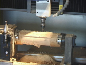
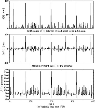
Figure 5.16 An example of the feed rate values given to NC machine tool, in which the total number of steps is 400, Fmax and Fmin are set to 2000 mm/min. and 600 mm/min., respectively.
It is observed, from the results shown in Fig. 5.16, that the feed rate ![]() is varied according to the curvature of the model surface. Note that the feed rate of 600 mm/min. appearing periodically is forcibly given every pick feed motion, when the rotary unit is rotated with a small angle (e.g., 0.56 degrees). The amount of the small angle depends on the ratio of y_length to y_pick as shown in Fig. 5.11. NC data were given to the NC machine tool MDX-650A through a standard RS232C interface using DNC (Direct Numerical Control) software. Generally DNC systems with a RS232C interface do not provide real-time communication but an asynchronous serial communication using XON/XOFF flow control, so that the variation of actual feed rate for time can not be obtained from the NC machin tool. Instead, the relation among the feed rate value
is varied according to the curvature of the model surface. Note that the feed rate of 600 mm/min. appearing periodically is forcibly given every pick feed motion, when the rotary unit is rotated with a small angle (e.g., 0.56 degrees). The amount of the small angle depends on the ratio of y_length to y_pick as shown in Fig. 5.11. NC data were given to the NC machine tool MDX-650A through a standard RS232C interface using DNC (Direct Numerical Control) software. Generally DNC systems with a RS232C interface do not provide real-time communication but an asynchronous serial communication using XON/XOFF flow control, so that the variation of actual feed rate for time can not be obtained from the NC machin tool. Instead, the relation among the feed rate value ![]() given to the NC machine tool, the distance d(i) and its increment ∆d(i) is plotted using the step number as the abscissa, as shown in Fig. 5.16. The relation between
given to the NC machine tool, the distance d(i) and its increment ∆d(i) is plotted using the step number as the abscissa, as shown in Fig. 5.16. The relation between ![]() and the point density in CL data can be observed from the result. The curvature can be estimated from the point density because the main-processor generates points written with gGOTO/ h statement in CL data according to the curvature and the tolerance. In the case of Fig. 5.16, the total machining time was reduced about 20% compared with the case of using a constant feed rate value of 600 mm/min. As can be seen, the proposed fuzzy feed rate generator provides a more intuitive and finely tunable feed rate function for the post process; however, the quantitative performance evaluation would depend on the combinatorial condition between the complexity of the relief design and the kind of the wooden material. Fig. 5.17 shows the paint rollers with an artistic design carved by the proposed system.
and the point density in CL data can be observed from the result. The curvature can be estimated from the point density because the main-processor generates points written with gGOTO/ h statement in CL data according to the curvature and the tolerance. In the case of Fig. 5.16, the total machining time was reduced about 20% compared with the case of using a constant feed rate value of 600 mm/min. As can be seen, the proposed fuzzy feed rate generator provides a more intuitive and finely tunable feed rate function for the post process; however, the quantitative performance evaluation would depend on the combinatorial condition between the complexity of the relief design and the kind of the wooden material. Fig. 5.17 shows the paint rollers with an artistic design carved by the proposed system.

5.5 Conclusion
In this chapter, an intelligent machining system based on a three-axis NC machine tool with a rotary unit has been introduced to efficiently and easily produce many kinds of artistic designed wooden paint rollers. A post-processor with the fuzzy feed rate generator has been also presented to effectively run the machining system. The post-processor allows the NC machine tool to easily transcribe a relief design from the surface on a flat model to it on a cylindrical workpiece. The fuzzy feed rate generator generates suitable feed rate values from CL data without using a feed rate statement according to the curvature of each relief design. By the fuzzy feed rate generator, it has been confirmed that not only the edge chippings on the cylindrical surface can be excluded but also the total machining time can be reduced about 20%. Experimental results, thus, have shown that artistically designed wooden paint rollers can be successfully carved using the proposed machining system.
In future works, we may plan to conduct similar machining experiments using other kinds of wooden materials than the glued laminated wood, and different relief designs. By evaluating the performances and taking the results in fuzzy rules, the fuzzy feed rate generator would be more flexible to the kinds of both wooden materials and relief designs for artistic paint rollers.
References
[1] Chen, C., Trivedi, M.M., Bidlack, C.R. Simulation and animation of sensor-driven robots. IEEE Trans. on Robotics and Automation. 1994; 10(5):684–704.
[2] Benimeli, F., Mata, V., Valero, F. A comparison between direct and indirect dynamic parameter identification methods in industrial robots. Robotica. 2006; 24(5):579–590.
[3] Corke, P. A Robotics Toolbox for MATLAB. IEEE Robotics & Automation Magazine. 1996; 3(1):24–32.
[4] Corke, P. MATLAB Toolboxes: robotics and vision for students and teachers. IEEE Robotics & Automation Magazine. 2007; 14(4):16–17.
[5] Luh, J.Y.S., Walker, M.H., Paul, R.P.C. Resolved acceleration control of mechanical manipulator. IEEE Trans. on Automatic Control. 1980; 25(3):468–474.
[6] Nagata, F., Kuribayashi, K., Kiguchi, K., Watanabe, K. Simulation of fine gain tuning using genetic algorithms for model-based robotic servo controllers. IEEE International Symposium on Computational Intelligence in Robotics and Automation. (196–201):2007.
[7] Nagata, F., Okabayashi, I., Matsuno, M., Utsumi, T., Kuribayashi, K., Watanabe, K., Fine gain tuning for model-based robotic servo controllers using genetic algorithms. 13th International Conference on Advanced Robotics. 2007:987–992.
[8] Hogan, N. Impedance control: An approach to manipulation: Part I - Part III. Transactions of the ASME, Journal of Dynamic Systems, Measurement and Control. 1985; 107:1–24.
[9] Nagata, F., Watanabe, K., Hashino, S., Tanaka, H., Matsuyama, T., Hara, K., Polishing robot using a joystick controlled teaching system. IEEE International Conference on Industrial Electronics, Control and Instrumentation. 2000:632–637.
[10] Craig, J.J. Introduction to ROBOTICS —Mechanics and Control Second Edition—. Addison Wesley Publishing Co., Reading, Mass; 1989.
[11] Nagata, F., Kusumoto, Y., Fujimoto, Y., Watanabe, K. Robotic sanding system for new designed furniture with free-formed surface. Robotics and Computer-Integrated Manufacturing. 2007; 23(4):371–379.
[12] Kawato, M. The feedback-error-learning neural network for supervised motor learning. In: Advanced Neural Computers. Elsevier Amsterdam; 1990:365–373.
[13] Nakanishi, J., Schaal, S. Feedback error learning and nonlinear adaptive control. Neural Networks. 2004; 17(10):1453–1465.
[14] Furuhashi, T., Nakaoka, K., Maeda, H., Uchikawa, Y. A proposal of genetic algorithm with a local improvement mechanism and finding of fuzzy rules. Journal of Japan Society for Fuzzy Theory and Systems. 1995; 7(5):978–987. [(in Japanese)].
[15] Linkens, D.A., Nyongesa, H.O. Genetic algorithms for fuzzy control part 1: Offline system development and application. IEE Proceedings Control Theory and Applications. 1995; 142(3):161–176.
[16] Linkens, D.A., Nyongesa, H.O. Genetic algorithms for fuzzy control part 2: Online System Development and Application. IEE Proceedings Control Theory and Applications. 1995; 142(3):177–185.
[17] Ferretti, G., Magnani, G., Zavala Rio, A. Impact modeling and control for industrial manipulators. IEEE Control Systems Magazine. 1998; 18(4):65–71.
[18] Sasaki, T., Tachi, S. Contact stability analysis on some impedance control methods. Journal of the Robotics Society of Japan. 1994; 12(3):489–496. [(in Japanese)].
[19] An, H.C., Hollerbach, J.M., Dynamic stability issues in force control of manipulators. IEEE International Conference on Robotics and Automation. 1987:890–896.
[20] An, H.C., Atkeson, C.G., Hollerbach, J.M., Model-based control of a robot manipulatorThe MIT Press classics series. Massachusetts: The MIT Press, 1988.
[21] Takagi, T., Sugeno, M. Fuzzy identification of systems and its applications to modeling and control. IEEE Transactions Systems, Man & Cybernetics. 1985; 15(1):116–132.
[22] Nagata, F., Watanabe, K., Sato, K., Izumi, K., An experiment on profiling task with impedance controlled manipulator using cutter location data. IEEE International Conference on Systems, Man, and Cybernetics. 1999:848–853.
[23] Nagata, F., Watanabe, K., Izumi, K., Furniture polishing robot using a trajectory generator based on cutter location data. IEEE International Conference on Robotics and Automation. 2001:319–324.
[24] Raibert, M.H., Craig, J.J. Hybrid position/force control of manipulators. Transactions of the ASME, Journal of Dynamic Systems, Measurement and Control. 1981; 102:126–133.
[25] Nagata, F., Hase, T., Haga, Z., Omoto, M., Watanabe, K. CAD/CAM-based position/force controller for a mold polishing robot. Mechatronics. 2007; 17(4/5):207–216.
[26] Nagata, F., Watanabe, K., Hashino, S., Tanaka, H., Matsuyama, T., Hara, K. Polishing robot using joystick controlled teaching. Journal of Robotics and Mechatronics. 2001; 13(5):517–525.
[27] Nagata, F., Watanabe, K., Kiguchi, K. Joystick teaching system for industrial robots using fuzzy compliance control. Industrial Robotics: Theory, Modelling and Control, INTECH, pages. (799–812):2006.
[28] Maeda, Y., Ishido, N., Kikuchi, H., Arai, T., Teaching of grasp/graspless manipulation for industrial robots by human demonstration. IEEE/RSJ International Conference on Intelligent Robots and Systems. 2002:1523–1528.
[29] Kushida, D., Nakamura, M., Goto, S., Kyura, N. Human direct teaching of industrial articulated robot arms based on force-free control. Artificial Life and Robotics. 2001; 5(1):26–32.
[30] Sugita, S., Itaya, T., Takeuchi, Y. Development of robot teaching support devices to automate deburring and finishing works in casting. The International Journal of Advanced Manufacturing Technology. 2003; 23(3/4):183–189.
[31] Ahn, C.K., Lee, M.C., An off-line automatic teaching by vision information for robotic assembly task. IEEE International Conference on Industrial Electronics, Control and Instrumentation. 2000:2171–2176.
[32] Neto, P., Pires, J.N., Moreira, A.P., CAD-based offline robot programming. IEEE International Conference on Robotics Automation and Mechatronics. 2010:516–521.
[33] Ge, D.F., Takeuchi, Y., Asakawa, N. Automation of polishing work by an industrial robot, – 2nd report, automatic generation of collision-free polishing path –. Transaction of the Japan Society of Mechanical Engineers. 1993; 59(561):1574–1580. [(in Japanese)].
[34] Ozaki, F., Jinno, M., Yoshimi, T., Tatsuno, K., Takahashi, M., Kanda, M., Tamada, Y., Nagataki, S. A force controlled finishing robot system with a task-directed robot language. Journal of Robotics and Mechatronics. 1995; 7(5):383–388.
[35] Pfeiffer, F., Bremer, H., Figueiredo, J. Surface polishing with flexible link manipulators. European Journal of Mechanics, A/Solids. 1996; 15(1):137–153.
[36] Takeuchi, Y., Ge, D., Asakawa, N., Automated polishing process with a human-like dexterous robot. IEEE International Conference on Robotics and Automation. 1993:950–956.
[37] Pagilla, P.R., Yu, B. Robotic surface finishing processes: modeling, control, and experiments. Transactions of the ASME, Journal of Dynamic Systems, Measurement and Control. 2001; 123:93–102.
[38] Huang, H., Zhou, L., Chen, X.Q., Gong, Z.M. SMART robotic system for 3D profile turbine vane airfoil repair. International Journal of Advanced Manufacturing Technology. 2003; 21(4):275–283.
[39] Stephien, T.M., Sweet, L.M., Good, M.C., Tomizuka, M. Control of tool/workpiece contact force with application to robotic deburring. IEEE Journal of Robotics and Automation. 1987; 3(1):7–18.
[40] Kazerooni, H. Robotic deburring of two-dimensional parts with unknown geometry. Journal of Manufacturing Systems. 1988; 7(4):329–338.
[41] Her, M.G., Kazerooni, H. Automated robotic deburring of parts using compliance control. Transactions of the ASME, Journal of Dynamic Systems, Measurement and Control. 1991; 113:60–66.
[42] Bone, G.M., Elbestawi, M.A., Lingarkar, R., Liu, L. Force control of robotic deburring. Transactions of the ASME, Journal of Dynamic Systems, Measurement and Control. 1991; 113:395–400.
[43] Gorinevsky, D.M., Formalsky, A.M., Schneider, A.Y. Force Control of Robotics Systems. New York: CRC Press; 1997.
[44] Takahashi, K., Aoyagi, S., Takano, M., Study on a fast profiling task of a robot with force control using feedforward of predicted contact position data. 4th Japan-France Congress & 2nd Asia-Europe Congress on Mechatronics. 1998:398–401.
[45] Takeuchi, Y., Watanabe, T. Study on post-processor for 5-axis control machining. Journal of the Japan Society for Precision Engineering. 1992; 58(9):1586–1592. [(in Japanese)].
[46] Takeuchi, Y., Wada, K., Hisaki, T., Yokoyama, M. Study on post-processor for 5-axis control machining centers —In case of spindle-tilting type and table/spindle-tilting type. Journal of the Japan Society for Precision Engineering. 1994; 60(1):75–79. [(in Japanese)].
[47] Xu, X.J., Bradley, C., Zhang, Y.F., Loh, H.T., Wong, Y.S. Tool-path generation for five-axis machining of free-form surfaces based on accessibility analysis. International Journal of Production Research. 2002; 40(14):3253–3274.
[48] Chen, S.L., Chang, T.H., Inasaki, I., Liu, Y.C. Postprocessor development of a hybrid TRR-XY parallel kinematic machine tool. The International Journal of Advanced Manufacturing Technology. 2002; 20(4):259–269.
[49] Lei, W.T., Hsu, Y.Y. Accuracy test of five-axis CNC machine tool with 3D probe-ball Part I: design and modeling. Machine Tool & Manufacture. 2002; 42(10):1153–1162.
[50] Lei, W.T., Sung, M.P., Liu, W.L., Chuang, Y.C. Double ballbar test for the rotary axes of five-axis CNC machine tools. Machine Tool & Manufacture. 2006; 47(2):273–285.
[51] Cao, L.X., Gong, H., Liu, J. The offset approach of machining free form surface. Part 1: Cylindrical cutter in five-axis NC machine tools. Journal of Materials Processing Technology. 2006; 174(1/3):298–304.
[52] Cao, L.X., Gong, H., Liu, J. The offset approach of machining free form surface. Part 2: Toroidal cutter in 5-axis NC machine tools. Journal of Materials Processing Technology. 2007; 184(1/3):6–11.
[53] Timar, S.D., Farouki, R.T., Smith, T.S., Boyadjieff, C.L. Algorithms for time optimal control of CNC machines along curved tool paths. Robotics and Computer-Integrated Manufacturing. 2005; 21(1):37–53.
[54] Heo, E.Y., Kim, D.W., Kim, B.H., Chen, F.F. Estimation of NC machining time using NC block distribution for sculptured surface machining. Robotics and Computer-Integrated Manufacturing. 2006; 22(5–6):437–446.
[55] Tarng, Y.S., Chuang, H.Y., Hsu, W.T. Intelligent cross-coupled fuzzy feedrate controller design for CNC machine tools based on genetic algorithms. International Journal of Machine Tools and Manufacture. 1999; 39(10):1673–1692.
[56] Zuperl, U., Cus, F., Milfelner, M. Fuzzy control strategy for an adaptive force control in end-milling. Journal of Materials Processing Technology. 2005; 164/165:1472–1478.
[57] Farouki, R.T., Manjunathaiah, J., Nicholas, D., Yuan, G.F., Jee, S. Variable-feedrate CNC interpolators for constant material removal rates along Pythagorean-hodograph curves. Computer-Aided Design. 1998; 30(8):631–640.
[58] Farouki, R.T., Manjunathaiah, J., Yuan, G.F. G codes for the specification of Pythagorean-hodograph tool paths and associated feedrate functions on open-architecture CNC machines. Machine Tools & Manufacture. 1999; 39(1):123–142.
[59] Frank, A., Schmid, A. Grinding of non-circular contours on CNC cylindrical grinding machines. Robotics and Computer-Integrated Manufacturing. 1988; 4(1/2):211–218.
[60] Couey, J.A., Marsh, E.R., Knapp, B.R., Vallance, R.R. Monitoring force in precision cylindrical grinding. Precision Engineering. 2005; 29(3):307–314.
[61] Tawakoli, T., Rasifard, A., Rabiey, M. Highefficiency internal cylindrical grinding with a new kinematic. Machine Tools & Manufacture. 2007; 47(5):729–733.
[62] Nagata, F., Kusumoto, Y., Hasebe, K., Saito, K., Fukumoto, M., Watanabe, K., Post-processor using a fuzzy feed rate generator for multi-axis NC machine tools with a rotary unit. International Conference on Control, Automation and Systems. 2005:438–443.
[63] Nagata, F., Watanabe, K. Development of a postprocessor module of 5-axis control NC machine tool with tilting-head for woody furniture. Journal of the Japan Society for Precision Engineering. 1996; 62(8):1203–1207. [(in Japanese)].
[64] Fujino, K., Sawada, Y., Fujii, Y., Okumura, S., Machining of curved surface of wood by ball end mill – Effect of rake angle and feed speed on machined surface. 16th International Wood Machining Seminar, Part 2. 2003:532–538.
[65] Nagata, F., Hase, T., Haga, Z., Omoto, M., Watanabe, K., Intelligent desktop NC machine tool with compliance control capability. 13th International Symposium on Artificial Life and Robotics. 2008:779–782.
[66] Duffy, J. The Fallacy of modern hybrid control theory that is based on orthogonal complements of twist and wrench spaces. Journal of Robotic Systems. 1990; 7(2):139–144.
[67] Lee, M.C., Go, S.J., Lee, M.H., Jun, C.S., Kim, D.S., Cha, K.D., Ahn, J.H. A robust trajectory tracking control of a polishing robot system based on CAM data. Robotics and Computer-Integrated Manufacturing. 2001; 17(1/2):177–183.
[68] Nagata, F., Mizobuchi, T., Tani, S., Hase, T., Haga, Z., Watanabe, K., Habib, M.K., Kiguchi, K., Desktop orthogonal-type robot with abilities of compliant motion and stick-slip motion for lapping of LED lens molds. IEEE International Conference on Robotics & Automation. 2010:2095–2100.
[69] Bilkay, O., Anlagan, O. Computer simulation of stick-slip motion in machine tool slideways. Tribology International. 2004; 37(4):347–351.
[70] Mei, X., Tsutsumi, M., Tao, T., Sun, N. Study on the compensation of error by stick-slip for high-precision table. International Journal of Machine tools & Manufacture. 2004; 44(5):503–510.
[71] Tsai, M.J., Chang, J.L., Haung, J.F., Development of an automatic mold polishing system. IEEE International Conference on Robotics & Automation. 2003:3517–3522.
[72] Tsai, M.J., Fang, J.J., Chang, J.L. Robotic path planning for an automatic mold polishing system. International Journal of Robotics & Automation. 2004; 19(2):81–89.
[73] Hocheng, H., Sun, Y.H., Lin, S.C., Kao, P.S. A material removal analysis of electrochemical machining using flat-end cathode. Journal of Materials Processing Technology. 2003; 140(1/3):264–268.
[74] Uehara, Y., Ohmori, H., Lin, W., Ueno, Y., Naruse, T., Mitsuishi, N., Ishikawa, S., Miura, T., Development of spherical lens ELID grinding system by desk-top 4-axes Machine Tool. International Conference on Leading Edge Manufacturing in 21st Century. 2005:247–252.
[75] Ohmori, H., Uehara, Y. Development of a desktop machine tool for mirror surface grinding. International Journal of Automation Technology. 2010; 4(2):88–96.
[76] Nagata, F., Hase, T., Haga, Z., Omoto, M., Watanabe, K. Intelligent desktop NC machine tool with compliant motion capability. Artificial Life and Robotics. 2009; 13(2):423–427.
[77] Nagata, F., Tani, S., Mizobuchi, T., Hase, T., Haga, Z., Omoto, M., Watanabe, K., Habib, M.K., Basic performance of a desktop NC machine tool with compliant motion capability. IEEE International Conference on Mechatronics and Automation, WC1-5. 2008:1–6.
[78] Nagata, F., Watanabe, K., Sato, K., Izumi, K. Impedance control using anisotropic fuzzy environment models. Journal of Robotics and Mechatronics. 1999; 11(1):60–66.
[79] Nagata, F., Otsuka, A., Yoshitake, S., Watanabe, K., Automatic control of an orthogonal-type robot with a force sensor and a small force input device. The 37th Annual Conference of the IEEE Industrial Electronics Society. 2011:3151–3156.
[80] Nagata, F., Watanabe, K. Feed rate control using a fuzzy reasoning for a mold polishing robot. Journal of Robotics and Mechatronics. 2006; 18(1):76–82.
[81] Nagata, F., Watanabe, K., Japanese Patent 4094781, Robotic force control method, 2008.
[82] Nagata, F., Tsuda, K., Watanabe, K., Japanese Patent 4447746, Robotic trajectory teaching method, 2010.
[83] Tsuda, K., Yasuda, K., Nagata, F., Kusumoto, Y., Watanabe, K., Japanese Patent 4216557, Polishing apparatus and polishing method, 2008.