2
More Ways to Transform Shapes

This chapter introduces a collection of transformation operations that allow you to have more control when creating complex shapes. You’ll learn how to rotate, reflect, and scale shapes; combine them with a shared hull; and round out their edges. These transformation operations will expand your modeling toolbox and allow you to create even more complex designs.
OpenSCAD Shape Transformations
First, you’ll learn how to use three transformation operations: rotate, mirror, and resize. A transformation operation is a bit of code that comes immediately before a shape to alter the shape’s position, size, or orientation. For illustrative purposes, we include a transparent gray outline in this chapter’s examples to indicate where the original, untransformed shape would have appeared.
Rotating Shapes with rotate
By default, OpenSCAD draws shapes so they’re oriented in a certain way. It draws sphere shapes centered at (0, 0, 0), for example, and cube shapes with a single corner at (0, 0, 0). Sometimes, though, you’ll want your shape to have a different orientation.
One way to alter a shape’s default position is to rotate it. To rotate a shape, specify the angle of rotation around each of the three axes, and express the angles of rotation in degrees, which can be positive or negative.
The following code snippet rotates a cuboid 90 degrees around the x-axis (Figure 2-1):
rotate([90, 0, 0]) cube([30, 20, 10]);
Figure 2-1: A cuboid rotated 90 degrees around the x-axis
First, write the name of the transformation, and then inside the parentheses, provide rotate with a vector in square brackets ([ ]) to group together the three axes of rotation. The first element in the vector is the degree of rotation around the x-axis, the second is the degree of rotation around the y-axis, and the third is the degree of rotation around the z-axis. Next, write the code for the shape you want to rotate. As always, use a semicolon (;) to end the entire statement.
Because you’re rotating the shape 90 degrees around the x-axis, its position the x-axis stays fixed, and it gets a new position on the yz-plane.
The following code snippet rotates the same cuboid around the y-axis (Figure 2-2):
rotate([0, 180, 0]) cube([30, 20, 10]);
Figure 2-2: A cuboid rotated 180 degrees around the y-axis
In this case, the shape’s position relative to the y-axis stays fixed, and its position on the xz-plane moves by 180 degrees.
You can also rotate a shape around two axes with a single operation, as in the following snippet (Figure 2-3):
rotate([-90, 0, -90]) cube([30, 20, 10]);
Figure 2-3: A cuboid rotated 90 degrees around the x-axis and 90 degrees around the z-axis
This cuboid is rotated around both the x- and z-axes. You might find it easier to imagine this operation as two separate transformations: one that rotates the shape around the x-axis and one that rotates it around the z-axis. To rotate the shape counterclockwise by 90 degrees in both directions, set the angle of rotation for those axes to –90.
Even though rotation around multiple axes is possible with the application of only one rotation operation, it’s best to separate the various rotations into individual, repeated transformations. This is because it is sometimes hard to predict which rotation will be applied first. Consider the difference in the location of the cuboid when the rotation around the z-axis is applied before the rotation around the x-axis (Figure 2-4):
rotate([-90, 0, 0]) rotate([0, 0, -90]) cube([30, 20, 10]);
Figure 2-4: A cuboid rotated –90 degrees around the z-axis, then rotated –90 degrees around the x-axis
Explicitly applying multiple rotations in their intended order will result in shapes ending up exactly where you’d like them to be after the rotations are applied.
Reflecting Shapes with mirror
Another way to change a shape’s default position is to reflect it across an imaginary 2D plane with the mirror transformation. As you might expect from the name of the operation, mirror creates a mirror-like reflection of your shape. The following statement reflects a truncated cone across the yz-plane (Figure 2-5):
mirror([10, 0, 0])
translate([0, 10, 0]) rotate([0, 90, 0]) cylinder(h=10, r1=5, r2=2); 
Figure 2-5: A truncated cone reflected across the yz-plane via the vector [10, 0, 0]
The vector you pass to mirror contains the x, y, and z coordinates that define an imaginary point. OpenSCAD then draws an imaginary line from the origin to that point and uses the 2D plane that is perpendicular to that line at the origin as the mirror, or plane of reflection.
To clarify this, Figure 2-6 shows the “mirror” as a semitransparent plane.

Figure 2-6: A truncated cone reflected across the yz-plane via the vector [10, 0, 0]
The “mirror” is perpendicular to the vector, shown in green, drawn from (0, 0, 0) to (10, 0, 0). Notice that you don’t have to use 10 as the x-axis value to create this mirror; any nonzero x-axis value would cause the mirror operation to behave the same way, as your goal is only to specify a vector that is perpendicular to the mirror. The mirror plane always contains the origin (0, 0, 0). In effect, the vector parameter of the mirror operation describes how the mirror is rotated.
The next statement reflects a cylinder across the xy-plane (Figure 2-7):
mirror([0, 0, 10]) cylinder(h=10, r1=2, r2=5);
Figure 2-7: A cone reflected across the xy-plane via the vector [0, 0, 10]
This example defines a point at (0, 0, 10), and the line from the defined point to the origin is perpendicular to the xy-plane. The mirror operation is particularly useful for quickly creating complex shapes that involve symmetry. Using the mirror operation in such cases may save you time, as you can focus on designing only one half of the object, and then use mirror to create the second half.
Note that the mirror operation does not copy the shape; it moves the shape into the mirrored position. If you want a fully symmetrical shape, first create the shape, and then repeat it with the mirror operation in front of it.
Scaling Shapes with resize
The resize operation allows you to stretch or shrink specific dimensions of individual shapes. When you resize a shape, you can specify its exact dimension along each axis. By stretching a sphere across a single axis, for example, you can turn it into an ellipsoid (an elongated sphere).
The following code snippet uses resize to scale a sphere with a radius of 1 into an ellipsoid (Figure 2-8):
resize([10, 10, 20]) sphere(1, $fn=100);
Figure 2-8: A sphere resized into an ellipsoid
Before writing the shape command, pass a vector to the resize operation to group together the new dimensions of the sphere along the x-, y-, and z-axes. As with all transformations, use a semicolon to end the entire statement.
The new ellipsoid stretches 5 units on either side of the origin along the x-axis, 5 units on either side of the origin along the y-axis, and 10 units on either side of the origin along the z-axis.
You could also use resize to transform a basic cylinder (Figure 2-9):
resize([10, 5, 20]) cylinder(h=5, r1=5, r2=5);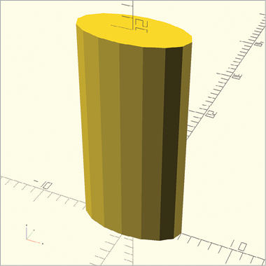
Figure 2-9: A resized cylinder
This statement resizes a basic cylinder with a height and two radii of 5 units so that the transformed cylinder stretches 10 units along the x-axis (through the origin), 5 units along the y-axis (also through the origin), and 20 units along the z-axis (from the origin).
More Ways to Combine 3D Shapes
In Chapter 1, you learned about three Boolean operations that allow you to combine multiple 3D shapes: union, difference, and intersection. You can also combine two shapes into one with the hull and minkowski operations.
Combining Shapes with hull
The hull operation creates a convex hull (or skin) around two shapes. To understand this, imagine stretching a balloon tightly around two or more shapes in order to create a single shape. For example, the following code creates a balloon surrounding both a sphere and a cube (Figure 2-10):
hull() {
    translate([10, 0, 0]) sphere(8);
    translate([-10, 0, 0]) cube([4, 4, 4], center=true);
}
Figure 2-10: A hull stretched around a small cube and a big sphere
The hull operation has the same syntax as the Boolean operations described in Chapter 1. It can combine two or more shapes, and as with the union operation, the order of shapes does not matter.
Combining Shapes with minkowski
The minkowski operation creates a Minkowski sum of a collection of shapes. This means it wraps the edges of one shape with the characteristic of a second shape. The following example wraps a sphere around the edges of a cylinder to create rounded edges (Figure 2-11):
$fn=50;
minkowski() {
    cylinder(h=15, r1=5, r2=5);
    sphere(4);
}
Figure 2-11: A sphere used to smooth the corners of a cylinder
The minkowski operation also has the same syntax as the Boolean operations described in Chapter 1. In this example, the edges of the cylinder become rounded edges because the smaller sphere has been embossed along the edges of the cylinder. It’s important to note that the minkowski operation produces a larger shape than the original cylinder, because wrapping the sphere around the original cylinder adds volume.
Combining Transformations
You can combine transformation operations by writing one operation in front of another. For example, the following code snippet applies the rotate operation before translate on each of three cylinders (Figure 2-12):
translate([5, 0, 0]) rotate([90, 0, 0]) cylinder(h=10, r1=4, r2=4);
translate([5, 0, 0]) rotate([0, 90, 0]) cylinder(h=10, r1=4, r2=4);
translate([5, 0, 0]) rotate([0, 0, 90]) cylinder(h=10, r1=4, r2=4);
Figure 2-12: Three cylinders, rotated and then translated
OpenSCAD first executes the innermost transformation (the operation directly to the left of a shape), then applies the outermost transformation. If you applied the transformations in the reverse order, you’d get a different result. The next snippet applies the translate operation before the rotate operation (Figure 2-13):
rotate([90, 0, 0]) translate([5, 0, 0]) cylinder(h=10, r1=4, r2=4);
rotate([0, 90, 0]) translate([5, 0, 0]) cylinder(h=10, r1=4, r2=4);
rotate([0, 0, 90]) translate([5, 0, 0]) cylinder(h=10, r1=4, r2=4);
Figure 2-13: Three cylinders, translated and then rotated
You get different results because OpenSCAD applies operations in order, starting with the transformation operation closest to the shape.
Summary
This chapter introduced several important operations for transforming shapes. You can now move, rotate, reflect, and resize shapes. You can also combine two shapes by forming a hull around them or by smoothing the corners of one shape with another.
Here are some important points to remember:
- You can apply transformation operations to single shapes and combined shapes.
- Combining shapes with the
unionoperation can reduce the number of transformation operations that you need to apply to a complex design. - Applying a series of
rotateoperations is often easier to manage than combining rotations into onerotateoperation. - Reflecting combined shapes with
mirrorcan save you time when you’re building symmetrical designs. - When you’re applying multiple transformation operations, order matters.
- The transformation operation closest to the shape is applied first.
In the next chapter, you’ll learn how to convert 2D shapes into 3D shapes, apply transformation operations to 2D shapes, and create surprisingly complex 3D shapes by combining and operating on basic 2D shapes.