1
3D Drawing with OpenSCAD

This chapter introduces the OpenSCAD 3D design software with its own built-in programming language. You’ll learn how to use text-based commands to draw the basic 3D shapes that will act as the building blocks for all the designs in this book. OpenSCAD’s easy-to-learn programming language, specifically designed for 3D printing, is a descriptive language that offers a more natural way of describing geometry than traditional programs.
Why Use OpenSCAD?
OpenSCAD is an open source program that is freely available for download. It is one of the most widely used 3D design software applications in the maker community, and as a result, many online resources are available. OpenSCAD was built to enable nondesigners to easily create 3D models. It does not have a graphical user interface like Photoshop. Instead, you define your design with text-based code, which makes it easier to move around different parts, change earlier steps in the design process, share sections of your designs with other people, discuss your design problems in forums, and email designs to others. You can do similar things in OpenSCAD as are possible with other high-end tools; however, OpenSCAD is quick to learn, simple to use, and more accessible.
Getting Started with OpenSCAD
Creating a 3D design with OpenSCAD is a two-step process. First, in the Editor window, type a code statement to give OpenSCAD instructions about what to display. Figure 1-1 shows a code statement to draw a simple OpenSCAD shape circled in red.

Figure 1-1: Code for a cube in the Editor window
This OpenSCAD code statement has two parts. The first part indicates the type of shape you want to draw (in this case, a cuboid). The second part, which contains what are called parameters, indicates the properties of that shape. Parameters allow you to specify values that modify the appearance of the shape. Parameters are always placed between parentheses ( ).
Next, draw your shape in the Preview window by clicking the Preview button (circled in red in Figure 1-2) to see a quick visual preview of your design.

Figure 1-2: Drawing a cube after clicking the Preview button
Drawing Basic 3D Shapes
In this section, you’ll learn how to write OpenSCAD code to draw cuboids (cubes or 3D rectangles), spheres, and cylinders, and you’ll learn how to import shapes from other design programs.
Drawing Cuboids with cube
Use the cube command to create a cuboid (as shown in Figure 1-2):
cube([5, 10, 20]);The first part of the statement, cube, indicates that you want to draw a cuboid. The parameters inside the parentheses modify the cube command by specifying how big you want your cuboid to be. The square brackets ([ ]) indicate a vector that organizes the three dimensions of your cuboid. The order of the numbers in the vector is important: 5 is the width of the cuboid along the x-axis, 10 is the length of the cuboid along the y-axis, and 20 is the height of the cuboid along the z-axis. Finally, mark the end of the statement with a semicolon (;).
Notice that one corner of the cuboid touches the origin: the point at which the three axes meet, represented by the coordinates (0, 0, 0).
Drawing Spheres with sphere
To draw a sphere, use the sphere command followed by the sphere’s radius in parentheses to indicate its size. For example, the following statement draws a sphere with a radius of 10 units (Figure 1-3):
sphere(10);
Figure 1-3: A sphere with a radius of 10 units
You can change the size of a sphere by changing its radius. Unlike cuboids, which might have three distinct measurements for width, length, and height, a sphere has the same measurements along all three axes. That’s why the basic sphere command has only one number inside the parentheses. As with the cube command, mark the end of the code statement with a semicolon. But unlike with the cube command, OpenSCAD centers a sphere around the origin.
Drawing Cylinders and Cones with cylinder
To draw a cylinder, use the cylinder command followed by parentheses containing the cylinder’s height and the length of the two radii of the circles that form its top and bottom. The following statement draws a cylinder with two radii of the same size (Figure 1-4):
cylinder(h=20, r1=5, r2=5);
Figure 1-4: A cylinder with a height of 20 units, a bottom radius of 5 units, and a top radius of 5 units
Because keeping track of the cylinder’s three parameters can be confusing, OpenSCAD allows you to label each parameter and include them in the command in any order. In parentheses, set the following values: h, which is the height of the cylinder along the z-axis; r1, which is the radius at the bottom of the cylinder; and r2, which is the radius at the top of the cylinder. As with the sphere and cube commands, use a semicolon to mark the end of the statement.
The two radii of a cylinder don’t need to have the same measurements. When they’re different, the cylinder looks more like a cone with its top cut off (or, a truncated cone, according to mathematicians), as shown in Figure 1-5:
cylinder(h=20, r1=5, r2=3);
Figure 1-5: A cone with a height of 20 units, a bottom radius of 5 units, and a top radius of 3 units
You can draw a pointed cone, like the one in Figure 1-6, by assigning one of the radii a radius of 0:
cylinder(h=20, r1=0, r2=5);
Figure 1-6: A pointed cone with a height of 20 units, a bottom radius of 0 units, and a top radius of 5 units
Notice also that, unlike the shapes drawn with the sphere and cube commands, cylinders are centered around the z-axis, with one face touching the xy-plane.
Importing 3D Models with import
OpenSCAD allows you to import shapes from other 3D design programs if they’re saved in the .stl format, which is a common format for 3D models. You can import these preexisting 3D shapes with the import command. For example, use the following statement to import a popular file called 3DBenchy.stl (Figure 1-7):
import("3DBenchy.stl");
Figure 1-7: An imported 3D model of a boat often used to calibrate 3D printers
To import a 3D shape, place the .stl file’s name within parentheses after the import command. Enclose the name of the file in quotation marks (" ") to indicate that the filename is literal text and should not be interpreted by OpenSCAD. Note that you should save the .stl file in the same folder/directory as your OpenSCAD program, and be sure to save your OpenSCAD program before you generate a preview of your design; otherwise, OpenSCAD might have trouble finding the file. Mark the end of the statement with a semicolon.
Modifying Basic Shapes
Some of the basic ways to alter the shapes you draw with OpenSCAD include moving or smoothing them.
Moving Shapes
If the design you’re creating has more than one shape, you’ll need to know how to move those shapes around the Preview window. Otherwise, by default, they will sit on top of each other, and you may not be able to see the shapes of different sizes. For example, consider the following design (Figure 1-8):
cube([20, 10, 10]);
sphere(5);
cylinder(h=30, r1=2, r2=2);
Figure 1-8: Multiple shapes drawn with default positioning
Centering Shapes with center=true
By default, the sphere command draws a sphere so that it’s centered around the origin; the cube, cylinder, and import commands don’t do this. If you want to draw other shapes so that they’re also centered around the origin, add the center=true parameter inside the parentheses, as in this snippet (Figure 1-9):
cube([5, 10, 20], center=true);
Figure 1-9: A cuboid centered around the origin
Now the cuboid’s center will be at (0, 0, 0). You can also add the center=true parameter to cylinder shapes in order to center cylinders and cones around the origin. It’s not possible to center imported shapes with center=true.
Moving Shapes to a Specific Location with translate
To move a shape to a specific location in the Preview window, use the translate operation. This operation modifies a shape as a whole so it’s included right before the shape it’s meant to modify.
For example, the following statement draws a cuboid that is shifted from its default position by 10 units in the negative direction along the x-axis, 20 units in the positive direction along the y-axis, and 0 units along the z-axis (Figure 1-10):
translate([-10, 20, 0]) cube([20, 10, 10]);
Figure 1-10: A translated cuboid with a starting corner at (–10, 20, 0)
The translate operation uses square brackets to group the x, y, and z dimensions into a vector. Similar to specifying the dimensions of a cube shape, the order of the numbers in the vector is important. The first number in the translation vector describes movement along the x-axis; the second describes movement along the y-axis; and the third describes movement along the z-axis. Finally, mark the end of the entire statement with a semicolon.
You may have noticed that the vector you use to modify the translate operation moves the shape’s starting corner—the corner that touches the origin by default. Figure 1-11 shows how the translate operation moves the cuboid relative to the origin (the original cube is shown in gray). You can use the axes legend to predict the location of your shapes after the translate operation has been applied.

Figure 1-11: A cuboid moved 10 units along the x-axis and 20 units along the y-axis, compared with the same-sized cuboid at the origin
To create a more complex design, you may need to move shapes around in different configurations. Use the translate operation in front of a command to move it into a different position. For instance, the following statements draw a cuboid, a sphere, and a cylinder in one Preview window (Figure 1-12):
translate([-10, 10, 0]) cube([20, 10, 10]);
translate([20, 0, 0]) sphere(5);
translate([0, 0, -10]) cylinder(h=30, r1=2, r2=2);
Figure 1-12: Three distinct shapes, translated from default positions
Both the sphere and cylinder move according to their respective center points, while the cube moves relative to the corner that touches the origin. Notice that the movement is different if you apply the same translation operations to a cube and cylinder that have been centered (Figure 1-13):
translate([-10, 10, 0]) cube([20, 10, 10], center=true);
translate([20, 0, 0]) sphere(5);
translate([0, 0, -10]) cylinder(h=30, r1=2, r2=2, center=true);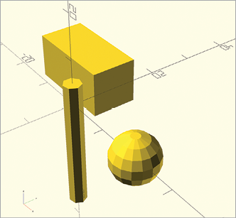
Figure 1-13: Three distinct shapes, translated from centered positions
Smoothing Curves with $fn
You might be wondering why the spheres and cylinders you’ve drawn so far don’t appear to be round, but instead are formed by a series of flat panels. That’s because OpenSCAD, like most 3D design software, uses a collection of straight lines to approximate a curve. To save on memory and reduce the processing time required to draw complex shapes, OpenSCAD uses a relatively small number of these lines by default. The cylinder shown in Figure 1-13, for example, uses only six line segments to approximate the curve of the circular faces of the cylinder.
To make your cylinders and spheres smoother, specify the number of line segments used to approximate a curve by including the $fn parameter. Setting $fn to 10, for instance, makes a cylinder look a bit rounder, because it draws the circumference of the cylinder with 10 line segments (Figure 1-14):
cylinder(h=20, r1=2, r2=2, $fn=10);
Figure 1-14: Approximating the curve of a cylinder with 10 line segments
As with other parameters, include $fn in the parentheses within the command.
Although the cylinder in Figure 1-14 is rounder than a default cylinder, it’s still not visibly round. Increase $fn to an even larger value in order to make the cylinder rounder (Figure 1-15):
cylinder(h=20, r1=2, r2=2, $fn=50);With 50 line segments, the curve in this cylinder looks a lot smoother. After a certain point, though, increasing $fn will stop showing any visible effect. Also, note that OpenSCAD takes longer to generate shapes with large $fn values (as there are more details to generate), so be sure to consider the trade-off between smoothness and computational overhead when you set $fn. Generally, $fn=50 will produce a “roundness” that is more than sufficient.
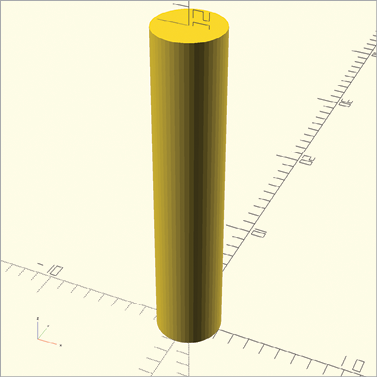
Figure 1-15: A cylinder with a curve approximated with 50 line segments
Combining 3D Shapes with Boolean Operations
Sometimes you’ll want to create shapes with features that are more complex than the basic shapes you’ve made so far. The Boolean operations in OpenSCAD allow you to combine multiple shapes, like cuboids, spheres, cylinders, and cones, into one shape (Figure 1-16). You can do this by using one of three operations: union, difference, or intersection.

Figure 1-16: An illustration of basic Boolean operations
The union operation groups two shapes together, the difference operation subtracts one shape from another, and the intersection operation keeps only the parts where two shapes intersect with each other.
Subtracting Shapes with difference
Let’s start by subtracting shapes with the difference operation (Figure 1-17):
difference() {
    cube([10, 10, 10]);
    sphere(5);
}
Figure 1-17: A sphere subtracted from a cuboid with the difference operation
Indicate a difference operation, followed by a set of parentheses, and then enter at least two commands between a set of curly brackets. Order matters when you use the difference operation; it keeps only the first shape, removing the parts of that shape where the remaining shapes intersect it. Notice in Figure 1-18 what happens when you exchange the order of the two shapes:
difference() {
    sphere(5);
    cube([10, 10, 10]);
}
Figure 1-18: A cuboid subtracted from a sphere with the difference operation
Reversing the operations creates a sphere with a slice missing, precisely where cube would have drawn a cuboid shape on top of the original sphere.
Debugging difference Operations with #
It can be easy to lose track of the shape you’re subtracting because it is no longer visible in the design. To make things easier, place a hash mark (#) in front of a subtracted shape to create a ghost version of the shape. The following code is identical to the code that drew Figure 1-17, except it uses a hash mark to render the sphere as a ghost-like image (Figure 1-19):
difference() {
    cube([10, 10, 10]);
    #sphere(5);
}
Figure 1-19: A ghost version of a subtracted sphere to help with problem-solving
Use the hash mark to help you debug your designs, and then when your design is correct, be sure to remove the hash mark from your code.
Avoiding “Shimmering Walls” with the difference Operation
When subtracting shapes with the difference operation, you may sometimes end up with “shimmering walls” like those in Figure 1-20.

Figure 1-20: Two cuboids subtracted from a larger cuboid create shimmering walls
The shimmering walls appear because the subtracted shapes share a face with the shape they’re being subtracted from. This creates an ambiguous scenario; should the face remain or be subtracted? Because of this concern, a model with shimmering walls isn’t 3D-printable.
To solve this issue, only subtract shapes that extend slightly beyond the size of the outer shape (Figure 1-21).

Figure 1-21: Two slightly larger cuboids subtracted from an outer cuboid
Once you’ve removed the ghost shapes, the remaining shape should contain no shimmering walls (Figure 1-22):
difference() {
    cube([10, 10, 10]);

    translate([-1, 2.5, 2.5]) cube([12, 5, 5]);
    translate([2.5, 2.5, -1]) cube([5, 5, 12]);
}
Figure 1-22: A subtracted shape that is fit for 3D printing
You should now be able to 3D-print this design.
Carving Out Overlapping Shapes with intersection
You can also carve away everything except the overlapping portion of two shapes by using the intersection operation (Figure 1-23):
intersection() {
    sphere(5);
    cube([10, 10, 10]);
}
Figure 1-23: The cutout of an overlapping sphere and cuboid, drawn with the intersection operation
First, indicate the intersection operation followed by parentheses, and then enter at least two commands between curly brackets. Unlike with the difference operation, the order in which you include the shapes doesn’t matter with intersection.
Grouping Shapes with union
To group shapes into a single entity, use the union operation (Figure 1-24):
union() {
    cube([10, 10, 10]);
    sphere(5);
}
Figure 1-24: A sphere and a cuboid grouped together with a union operation
The union operation combines all the shapes inside the curly brackets into one shape. Indenting all the lines that come between the curly brackets makes your code readable and easy to understand. Similar to intersection and difference, there’s no way to modify the union operation, so you’ll never need to put any information inside its parentheses.
Although it appears as if you can combine shapes by simply drawing them on top of each other, each shape will still remain a separate entity. This can be a problem when using the difference operation, as that operation subtracts only from the first shape inside the curly brackets. To avoid this problem, you can group multiple shapes into one shape by using the union operation. Include this grouped shape within difference as the first shape. For example, the following program uses the union operation to subtract a sphere from two shapes at once (Figure 1-25):
difference() {
    union() {
      cube([10, 10, 10]);
      cylinder(h=10, r1=2, r2=2);
    }
    sphere(5);
}
Figure 1-25: A sphere subtracted from a cylinder and a cuboid grouped together with union
OpenSCAD first combines the cube and cylinder into one shape, and then subtracts the sphere from that new shape. Without the union operation, OpenSCAD would, instead, subtract both the cylinder and sphere from the cuboid (Figure 1-26).

Figure 1-26: A sphere and a cylinder subtracted from a cuboid
Once you’ve created a complex shape with difference, intersection, or union, a computer can easily break it into geometric primitives to generate an accurate 3D model of your design. You can then print this complex 3D model on a 3D printer or import it into a 3D virtual reality program.
Getting Ready for 3D Printing
When you’re ready to send your OpenSCAD design to another application for 3D printing, you’ll need to export an .stl version of your design from OpenSCAD. You can then import this file into your 3D printing preparation software to adjust the settings, then turn it into a physical object with a 3D printer.
To export an .stl version of your design, first render your design by clicking the Render button (circled in red in Figure 1-27). Whereas Preview generates a quick picture of your model, Render fully calculates all of the surfaces needed to define the model. Especially complex designs require more surfaces and might have slow Render times as a result.

Figure 1-27: Rendering a design with the Render button
Finally, export your design as an .stl by selecting File▶Export▶Export as STL (Figure 1-28).

Figure 1-28: Exporting a design as an .stl file
Summary
Congratulations! You should now be able to create designs that include cuboids, spheres, and cylinders in any size and draw them in OpenSCAD’s Preview window. You can also import 3D shapes, smooth curves, and move shapes to anywhere along the x-, y-, and z-axis. Finally, you also should know how to create complex designs out of basic shapes by grouping, subtracting, and cutting out overlapping shapes.
Here are some important points to remember:
- The name of an OpenSCAD command describes the type of shape you’d like to draw.
- Commands are followed by parentheses. Information inside parentheses
( )modifies a command. The values inside the parentheses are called parameters. You can think of parameters as adjectives that describe characteristics of the shape. - A semicolon (
;) marks the end of most statements. Statements can include both commands and operations. - Use the
translateoperation to move your shapes around the Preview window. Indicate the amount and direction of movement by changing the vector parameter of thetranslateoperation. - Square brackets (
[ ]) collect numbers together to form a vector. The order of the numbers inside a vector is important. - Boolean operations use curly brackets (
{ }) to collect multiple shapes together. These curly brackets also form a complete OpenSCAD statement and do not require a semicolon to end the statement. - Parentheses, square brackets, and curly brackets always come in pairs.
$fncan be used as a parameter to change the smoothness of a single shape. You can also set$fnto a high value at the beginning of your code to generate smooth curves for every shape in a design. High values for$fncan result in slow rendering times.- Use indentation to help make your code readable and easy to understand.
- A design must be rendered before it can be exported as an .stl file.