
CHAPTER EIGHT
File Systems—FAT 12/16
WE ARE CONTINUING with the natural sequence of events of how data is stored electronically. We discussed the boot process and partition table to exemplify concepts of how data is stored on the hard drive. We follow the computer boot sequence, as it is the primary way in which data are “assembled” into information which we can use, or for which we may be searching as part of an investigation.
The next piece of “data assembly” is more logical in nature and actually brings data to a state in which we can actually access and use it. This chapter covers file systems and concepts related to the “mounting” of data into identifiable information.
In the previous chapter we have started to cross the line between the physical storage of data and the logical storage of data. The definition of physical being the actual on/off state of the bit and its location on the hard drive platter, as defined by Cylinder, Head, and Sector (CHS) and Logical Block Address (LBA), with the partition defining the more physical boundary of data as they reside in the disk itself.
We discussed how contiguous physical bits are assembled together into physical constructs called sectors. Consecutive sectors are then logically assembled into what is called a cluster. As discussed, a cluster is a logical unit of storage which is made up of at least one sector.
When a file is saved it automatically receives a full cluster as a “container” for its storage. If the file is smaller than the container, it only occupies that one cluster. If the file is larger than a cluster then it will occupy as many clusters as needed until its contents are allocated.
Here is a brief example to reinforce this important concept.
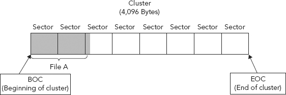
Let’s assume a cluster contains eight sectors; at 512 bytes per sector the total cluster size would therefore equal 4,096 bytes (8 × 512). Let’s take a basic file, File A, whose size is a total of 1,040 bytes.
Our “File A” occupies one full cluster. Determining how many sectors File A occupies within this single cluster simply involves dividing File A’s size (1,040 bytes) by 512 bytes per sector. We see that File A uses two full sectors and 16 bytes of the third sector in the cluster (see Figure 8.1).
FIGURE 8.1 Sector Utilization of a File Stored within a Cluster
Clusters do not necessarily need to be used contiguously, meaning a large file needing multiple clusters may save a piece of the file to one cluster and another piece to another cluster somewhere else on the hard drive. Large files will often need to be fragmented in such a manner in order to find a resting place. Logically it appears as one file but physically it is fragmented throughout the drive.
We often hear the phrase “defrag a hard drive.” Defragmentation of the hard drive means to actually move the data so that the clusters are physically next to one another, therefore not fragmented. When files are heavily fragmented the system will need to reassemble those clusters before presenting data. The hard drive must spin around and pull components together. This takes time and, when multiplied, may impede overall performance and operational efficiency.
A file system is a tool used for storing and retrieving data on a computer. It is the tool that tracks the allocation of the clusters, and it allows for a hierarchy of directories, folders, and files. A file system addresses and manages all the clusters contained within a volume.
A file system is usually defined during the creation of a partition; it is at this point that the partition “becomes” a volume. File systems determine how and where files are placed on a hard drive, with the goal of trying to optimize data retrieval speeds. As discussed, saving files to contiguous clusters is optimally more efficient for data access and retrieval.
When looking for a file, the operating system needs a system or method to determine where on the hard drive the file has been placed. Imagine if you will a Microsoft Word document saved on a hard drive being analogous to a book in a library. It is nice and convenient for us to click on an icon and access our document. As users, we have no care as to where that document resides physically on the hard drive.
We may know where that document resides logically within a folder structure, but we are oblivious (and justifiably so), as to which specific bits on the hard drive are allocated to this individual document. This is not something the end user needs to be concerned with; however, it is imperative that the file system knows otherwise when we click on the Word document icon nothing would happen.
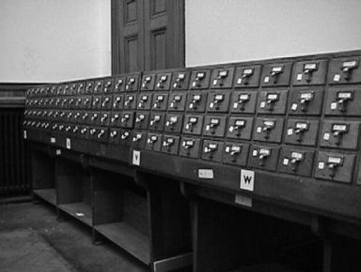
To find a book within a library one simply looks up the name of the book (or title, author, and/or other pertinent information) in a card catalog (see Figure 8.2).
FIGURE 8.2 Library Card Catalog System (circa mid-twentieth century)
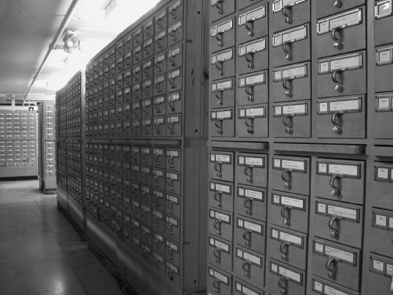
This directs a potential reader to a certain aisle (see Figure 8.3).
FIGURE 8.3 Physical Storage Location of Book within a Library
Source: © GlobalTrekk Photos, used with permission.

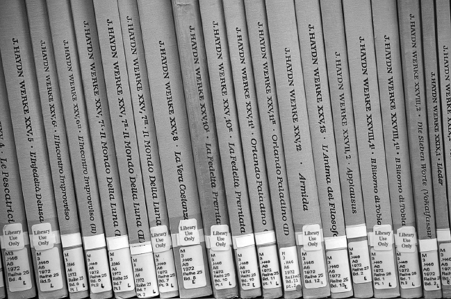
And then points to the book’s exact location within the library (see Figure 8.4).
FIGURE 8.4 Exact Location of Desired Book within a Library (specific floor, aisle, shelf, and position on the shelf)
Source: © GlobalTrekk Photos, used with permission.
Ah, the good ol’ days . . . now we search for the same book electronically!
Imagine, for instance, if libraries did not have a cataloging system (such as the Dewey Decimal System) for all its books. A library contains thousands and thousands of books. Anyone who has ever stepped foot in a library can imagine how daunting a task it would be to locate a specific book with no idea of its exact location. Finding a single book could literally take hours, days, or even weeks, depending on the number of books residing within the library. The cataloging system used within a library makes finding the exact location of a book relatively painless (see Figure 8.5).
The catalog entry will contain information about the book such as author, title, dates, and location within the library. File systems in computers must use a similar method, otherwise locating files would be impossible. The computer’s file system will contain information about the file such as the file’s name, size, and starting location (address on the disk).
The information contained within this filing system is often referred to as Metadata. Metadata in its simplest definition is data about data. It is essentially those data that would exist on the physical card residing within the manual card catalog itself. The card would not contain the entire contents of the book (the story), but rather would contain the title, author, publishing date, and the exact location of the book within the library.
We have discussed metadata and will again as it is relevant here in our discussion of file systems. Metadata consists of information that characterizes data. In essence, metadata answers the who, what, when, where, why, and how about the data/document. Whenever an electronic document is created, opened, or saved, metadata is altered. Operating systems require file systems in order for them to function, and information about these file systems is contained in part in metadata.
Metadata are used for a variety of reasons, such as to enhance publishing, editing, viewing, filing, and retrieval. Some metadata are accessible through operating software or parent software interfaces. For example, open a folder on a Windows operating system and select the “Details” view. Information made available and visible includes name, size, type, and document modified date of its contents. Open the “properties” tab on an MS Word document and more information about the document is revealed. This is metadata. Other metadata is only accessible through HEX editors or other, more specialized tools.
Here are some examples of metadata that may be stored along with a document:
- Your name
- Your initials
- Your company or organization name
- The name of your computer
- The name of the network server or hard disk where you saved the document
- Other file properties and summary information
- Non-visible portions of embedded OLE objects
- The names of previous document authors
- Document revisions
- Document versions
- Template information
- Hidden text
- Comments
The concept of metadata can be seen in many day-to-day areas other than electronic evidence. As we discussed earlier, the data contained within a card catalog is metadata.
Take a look, for example, at the very simple graphic of planet Earth as shown in Figure 8.6.
FIGURE 8.6 Planet Earth and Metadata

Longitude and latitude (maps in general) contain metadata about our planet, Earth. They are artificial; after all, our planet does not have grid lines going through it, or superimposed upon it. This metadata was necessary to allow an individual to identify a unique location on the planet, and it was principally designed by those who needed to navigate the oceans, which are notably lacking in visible features. If it weren’t for these metadata, we might never have mapped the Earth correctly in its entirety.
Metadata is often imperative to accessing and identifying the object it defines. Just as a map aids us in locating an unfamiliar geographic location or a card catalog aids in locating one book out of thousands, so too does a file system aid us in locating the few bits out of billions that make up a file.
There are different library filing systems such as the Dewey Decimal System or the Library of Congress’ classification system. The same is true for computing file systems. Microsoft Windows operating systems have unique file systems, as do Apple-, Linux-, and Unix-based operating systems.
Some varieties of computer operating systems with corresponding file systems are shown in Table 8.1.
TABLE 8.1 Computer Operating Systems with Corresponding File Systems
| Operating System | File System Used |
| PC floppy disks | FAT 12 only |
| DOS | FAT 16 only |
| Windows 3.x | FAT 16 only |
| Windows 95 | FAT 16 or FAT32 |
| Windows 98 | FAT 16 or FAT32 |
| Windows ME | FAT 32 |
| Windows 2000 | FAT 16, FAT 32 or NTFS |
| Windows XP | NTFS |
| Windows Server 2003 | NTFS |
| Windows Vista | NTFS |
| Windows 7 | NTFS |
| HFS | MAC |
| Ext2, Ext3 | Linux |
| UFS | Unix |
FILE ALLOCATION TABLE (FAT) FILE SYSTEM
The FAT filing system is a bit dated and used in earlier Microsoft operating systems. It is discussed here to best explain and exemplify the concepts involved within file systems. Any one specific file system will likely become obsolete, but the general concepts are worth examination. The important thing here is to understand the concept of how file systems work.
FAT is used to place files in free clusters of space on the hard drive. This is not like a videocassette tape, phonographic record, or even a CD, where files are placed in a physical order from beginning to end. Each entry in the File Allocation Table corresponds directly to one cluster, at which point the cluster becomes allocated to that data referenced in the FAT.
As discussed, there are different versions of the FAT filing system: FAT 12, 16, and 32. File Allocation Table entries can be 12, 16, or 32 bits long corresponding to FAT 12, FAT 16, or FAT 32 respectively. It is these table entries which are used to identify or demarcate a cluster. A single file is allocated (or saved) to a cluster, even if the file does not completely fill up the entire cluster. A large file of course may need to be allocated across multiple clusters.
The FAT filing system consists of three main components:
1. Volume Boot Record
2. Directory Entries
3. File Allocation Table
Volume Boot Record (VBR)
The volume boot record is also known as volume boot sector or volume boot. This is typically the first sector of a partition. As the Master Boot Record (MBR) defines the partitions of a physical disk, the VBR performs a similar function for an individual volume/partition. It defines the partition type (file system) and holds the parameter information such as bytes per sector and sector per cluster within the volume.
We do not cover all the byte offsets within the VBR, but do discuss those that bring key concepts to light. For additional information on specific byte offset values within the VBR and further discussions on the VBR, it is suggested that the reader review the following appendices:
Appendix 8A: Partition Table Fields
Appendix 8B: File Allocation Table Values
Appendix 8C: Directory Entry Byte Offset Description
Appendix 8D: FAT 12/16 Byte Offset Values
Appendix 8E: FAT 32 Byte Offset Values
We see in Figure 8.7 that byte offset 54–58 identifies the file system, in this example, FAT 16. If you “convert” the HEX values 46:41:54:31:36 (as bytes) to ASCII as shown in Table 8.2, the individual HEX value FAT 16 is returned. See the individual HEX values marked in Figure 8.8.
FIGURE 8.7 File System Type Identified at Byte Offset 54–58
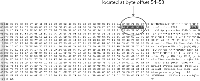
FIGURE 8.8 Standard ASCII Chart/ASCII Table—HEX to Decimal Code Conversion
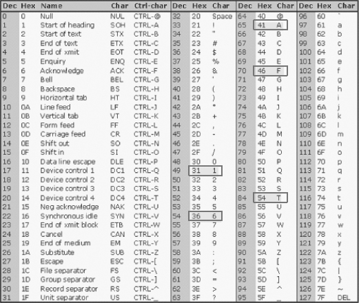
TABLE 8.2 VBR Byte Offset 54–58 HEX Value and ASCII Equivalent
| Byte Offset | HEX Value | ASCII Character Equivalent |
| 54 | 46 | F |
| 55 | 41 | A |
| 56 | 54 | T |
| 57 | 31 | 1 |
| 58 | 36 | 6 |
Bytes per Sector
In Chapters 4 and 5 we discussed the fact that typically there are usually 512 bytes per sector. This is pretty standard knowledge; however, just the same, this fact but must be defined somewhere in order for the OS to know that this is the bytes per sector size that the system is using.
In FAT that somewhere is in the Volume Boot Record, at byte offset 11–12. In our example, the HEX editor shown in Figure 8.9, we see the HEX values 00 02.
FIGURE 8.9 Determining Bytes per Sector from the VBR at Byte Offset 11–12
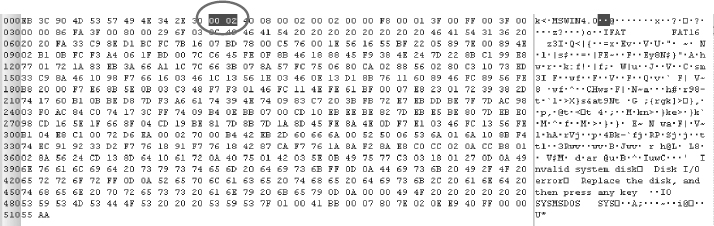
If we pull out the old scientific calculator to determine the decimal equivalent to HEX 00 02 (or simply 2) we find the answer to be 2.
But, wait a minute! Two bytes per sector? Wasn’t it pretty standard to have 512 bytes per sector?
The HEX value is correct. Remember, it all has to do with how the operating system instructs the code to process and handle data, and in this case the endianness is important as it is reversed, from the perception of reading the value from left-to-right (big endian) to reading the data’s value from right-to-left or in this case, little endian.
Therefore, the HEX value is 02 00, or simply 200. Again, back to our calculators, and we see that the decimal equivalent of HEX 200 is indeed 512. Thus there are 512 bytes per sector!
Sectors per Cluster
The sectors per cluster are also defined here in the VBR. This value is defined in sector offset 13. (See Figure 8.10.)
FIGURE 8.10 Determining Clusters per Sector from the VBR at Byte Offset 13
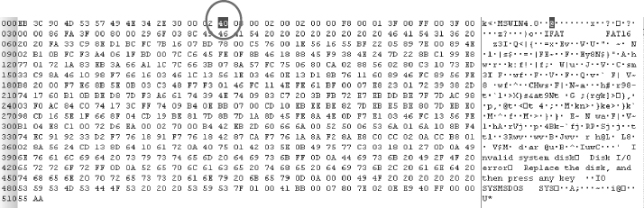
The HEX value of sector offset 13 is 40 (see Figure 8.10). However, if we convert HEX 40 first to its decimal equivalent we get 64, then decimal 64 to its ASCII equivalent; we get “@.” However, this value (HEX 40) is actually used to perform a mathematical function. So, we convert the HEX value 40 to a decimal value (again back to our scientific calculator).
After performing the calculation with the scientific calculator, we see that the HEX value 40 returns a decimal equivalent of 64.
As we have already touched upon, typically there are 512 bytes per sector. This is fairly common and as with the sector size of our example VBR in Figure 8.9, we have determined it to be 512 bytes. We now have identified how many sectors exist per cluster, again in our example (Figure 8.10), to be 64.
If we multiply the number of bytes per sector by number of sectors per cluster we arrive at the total size of the cluster, in bytes. Thus:
(Bytes per sector) × (Sectors per cluster) or 512 × 64, which yields a value of 32,768 bytes per cluster.
A full cluster then, in our example, is 32K bytes.
To verify this, all we need to do is view a document’s properties, a document that has been saved to a FAT 16 file system.
See Figure 8.11, where we have created a document named “hello.txt.” If we view the document’s properties we see that the document’s size is 5 bytes, and that the size on disk (or cluster allocation) is 32,768 bytes.
FIGURE 8.11 Document Properties Window for Document hello.txt
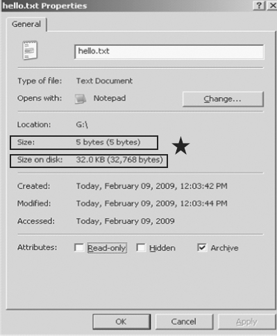
The document in Figure 8.11 is allocated to at least one cluster and in this case only one; however, we see a very inefficient use of space. As we discussed in the tech review at the beginning of this chapter, when a file is written to a drive it automatically receives at a minimum, one cluster.
In this example, the file “hello.txt” would be allocated 32KB of disk space, regardless of its size. So, a small, 5-byte text document would get the entire 32,768-byte cluster.
As you can imagine, the FAT 16 file system is inefficient in its use of space. What happens to the remaining space? Nothing! It is allocated space, as it is part of the cluster assigned to the file “hello.txt,” but was not required due to the small size of the file “hello.txt.”
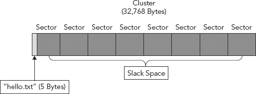
The unused space contained within the cluster reserved for “hello.txt” is referred to as slack space. It is allocated space but does not contain content from the saved file “hello.txt.” The slack space will contain remnants of data that was stored in that allocated cluster previously. (See Figure 8.12.)
FIGURE 8.12 Slack Space (aka File Slack)
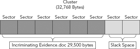
For example, say a 29,500-byte document named “Incriminating Evidence.doc” was allocated to that same cluster previously. (See Figure 8.13.) That “Incriminating Evidence.doc” document was sent to the recycle bin and then the recycle bin was emptied, thereby officially making that cluster available or unallocated.
FIGURE 8.13 Incriminating Evidence.doc
Later, the file “hello.txt” was saved and it was allocated to that same cluster. Being that “hello.txt” is only 5 bytes in size it would only need the first five bytes of that cluster in order to contain itself. This would then leave 32,763 bytes of file slack. (See Figure 8.14.)
FIGURE 8.14 32,763 Bytes of Slack Space

We determine this by knowing the total number of bytes per cluster (32,768) (i.e., cluster size), less the five bytes for the new file, “hello.txt,” giving us the remaining number of bytes left in the original cluster allocated to the file “hello.txt,” 32,763 bytes, which is now referred to as slack space.
The previous file saved to the cluster, “Incriminating Evidence.doc” was 29,500 bytes. Much of this file would therefore also remain in what is now file slack.
We determine this by knowing the total number of bytes (29,500 bytes) of the old file, “Incriminating Evidence.doc” less the five bytes of the new file, “hello.txt,” giving us 29,495 bytes of slack space, which would contain the remnants of the previous file to occupy this space: “Incriminating Evidence.doc.” (See Figure 8.15.)
FIGURE 8.15 29, 495 Bytes of Deleted File Remaining in Slack Space

As you can imagine there may be some worthwhile data contained within the 29,495 bytes of slack space, especially with a document named “Incriminating Evidence.doc.”
Slack space can be further broken down into File Slack and Sector Slack. There are differences but both pertain to the slack space described.
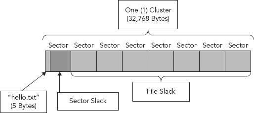
When a file is saved it is allocated to a cluster. As discussed, clusters are comprised of sectors. When saved, a file is saved to the first sector of the cluster. If the file size exceeds the sector size (512 bytes), then it is saved to the next sector, and the next cluster, and the next, and so on and so forth, until the entire file is stored. The unused sectors within a cluster are often referred to as file slack while the unused bytes in a sector are often referred to as sector slack. (See Figure 8.16.)
FIGURE 8.16 Sector and File Slack
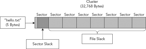
To continue with our example: 32,768 bytes is our cluster size, less the five bytes of the new file, “hello.txt,” equals 32,763 bytes of file slack in this cluster. With 512 bytes as the sector size, less the five bytes of the new file, “hello.txt”, we now have 507 unused bytes in the sector, which we refer to as sector slack.
Slack space will be preserved (not overwritten) unless:
1. The file assigned to that allocated space (“hello.txt”) is changed and/or made larger in size, thereby writing to the slack space, (its allocated space).
2. The file, “hello.txt” is deleted from the recycle bin, therefore making the entire cluster available or unallocated. This may result in another file being allocated to that cluster. Note—if that new file is the same size or smaller than the previous file (“hello.txt”) much of the data contained within the slack space could remain preserved.
HEX can be converted to ASCII as seen in a HEX editor. However, not all HEX will appear as text or legible ASCII. Most programming code will not have a human legible ASCII presentation. In fact, the only HEX that will have a legible representation is the HEX value that may be called up by the software code for various display purposes.
For example, when going into Disk Management software and viewing disk partition information, we will see the file system type is FAT 16. How does the computer know to display this information and, more precisely, how does the computer know what to display? The Disk Management programming code will tell the system to go to byte offset 54–58 in the first sector of the partition and display that information in ASCII, “FAT16,” as displayed in Figure 8.7. These HEX values do not have a mathematical function; they are used for display purposes. Information that will be displayed will usually be legible in ASCII.
Notice for example the messages in the Volume Boot Record Figure 8.17, “Invalid System Disk,” “Disk I/O error,” and “Replace the disk, and press any key.” This text is retrieved by code and displayed as error messages when there is an error during boot up. It is for this reason it is legible, because it may be called up by code and displayed as a message.
FIGURE 8.17 ASCII Values of HEX Entries in the VBR
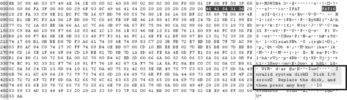
Usually, legible ASCII seen in HEX editors does not perform mathematical calculations or function as programming code; it is simply text that can be extracted and displayed by the system.
The second piece of the FAT Filing system, are the directory entries. Remember that the FAT filing system consists of three main components:
1. Volume Boot Record
2. Directory Entries
3. File Allocation Table
Every file and folder/directory is referenced in a separate 32-byte entry called a directory entry. A unique directory entry exists for each file and directory stored on a disk. Each directory entry contains information such as:
1. Names of the file and directory. For example: “hello.txt.”
2. Time and data metadata.
3. Location—file names have to be linked to the actual data comprising the file and therefore there must be an attribute pointing to where the data actually starts, that is, the starting cluster.
4. Size of the file—its length.
These entries are located in the clusters allocated to the file’s parent directory.
Figure 8.18 is an example of the entry for our example document, “Incriminating Evidence.doc,” represented in ASCII.
FIGURE 8.18 Directory Entry for Document “Incriminating Evidence.doc”
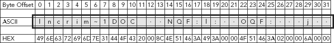
Notice again each entry is 32 bytes in length. The total number of directory entries available is determined when volume is formatted and is fixed at 32 sectors within FAT 12/16. So, 32 sectors are allocated for directory entries and each directory entry itself is 32 bytes in length.
The following is a brief overview of the byte offset values of the directory entry in Figure 8.18:
- Byte Offset 0. The first character of the file name or status byte. When a file is deleted this character will be replaced with a “~” which tells the system that the space previously occupied by that file is now available, or unallocated. This is an important byte as it is what identifies a file as being deleted, or more appropriately, it identifies the space as unallocated. Note: the rest of the 31 bytes of the directory entry and the actual file remain intact until the space is eventually reallocated and potentially overwritten.
- Byte Offset 1–7. File name continued. Here we see a limitation of the FAT file system and it is referred to as Short File Names (SFN). Eight characters reserved for a file name is constrictive to say the least. Well, the file system takes this into consideration and appends the file name. The “~” in Byte Offset 6 implies a shortened name.
The 1 in Byte Offset 7 implies that this is the first document to contain those first six characters. For example, say another document was created called “Incrimination Study.doc.” It would contain the same first six characters. Because of FATs limitations and in order to differentiate between these documents, FAT would name the second document, “Incrimination Study.doc,” as Incrim~2.
- Byte Offset 8–10. Three character file extension. Extensions are used mostly by Microsoft Operating Systems and not needed or used by other operating systems. For more information regarding file extensions and types please refer back to Chapter 4.
- Byte Offset 11. Attributes—Read only, hidden, and so on.
- Byte Offset 12–13. Reserved.
- Byte Offset 14–17. Create time and date of file stored as MS_DOS 32-bit timestamp (discussed in Chapter 11).
- Byte Offset 18–19. Last accessed, date only, no time.
- Byte Offset 20–21. Two high bytes of FAT 32 starting cluster; FAT 12/16 will have zeros.
- Byte Offset 22–25. Last written time and date of file again as MS-DOS 32-bit timestamp (discussed in Chapter 11).
- Byte Offset 26–27. Starting cluster for FAT 12/16; two low bytes of the starting cluster for FAT 32.
- Byte Offset 28–31. Size in bytes of the file. Will be 0 for directories.
Remember, the FAT Filing System consists of three main components:
1. Volume Boot Record
2. Directory Entries
3. File Allocation Table (FAT)
Here we will discuss and examine this third piece of the FAT filing system. The nomenclature for describing and writing the various FAT types can be shown as either FAT12, for example, with no space, or FAT 12, with a space. Either way is acceptable and used equally.
The FAT can be thought of as a map of all the clusters (a cluster, you will recall, is the smallest unit used to store files) on the hard drive. The FAT contains an entry for each available cluster on the disk.
The FAT tracks which clusters are allocated or unallocated (available or unavailable), tracking those allocated units (or clusters) which contain the file or data. Many times a document may surpass one allocation unit (one cluster) and need to be stored in multiple noncontiguous allocation units, or clusters; it is the FAT that will link these clusters.
The FAT finds the clusters that follow the starting cluster for any given file or directory. As we have discussed, files are not necessarily saved in a physically contiguous manner on the hard drive. It is therefore the job of the FAT to track the sequence of those clusters that will be combined (or concatenated) to create the saved file. The FAT also tracks bad clusters.
A visual depiction of the FAT is shown in Figure 8.19.
FIGURE 8.19 The File Allocation Table
In the FAT filing system, the FAT is by default identified as FAT1. The FAT maintains a spare copy of itself, identified as FAT2, and is stored immediately following the entry for FAT1. The FAT for FAT 12, 16, or 32 begins at a location determined by that drive’s structure, and the length of the table depends on the disk size and formatting.
The size of the FAT entries depends upon the version of FAT. In fact, the FAT version (FAT 12, 16, or 32) is named after the amount of bits contained within each entry of the FAT:
FAT 12 has 12-bit entries, FAT 16 has 16-bit entries, and FAT 32 has 32-bit entries.
This naturally imposes limitations based upon the number of bits in the FAT, but how? Let’s take a closer look at each FAT type.
FAT 12
Each entry is 12 bits in size, and each of these 12-bit entries in the FAT is representative of an actual cluster, the smallest allocation unit on a disk. Table 8.3 tells us how many values or possible outcomes can be achieved with 12 bits.
TABLE 8.3 Values or Possible Outcomes That Can Be Achieved with 12 Bits
| Number of Bits | Possible Number of Values or Outcomes |
| 1 | 2 |
| 2 | 4 |
| 3 | 8 |
| 4 | 16 |
| 5 | 32 |
| 6 | 64 |
| 7 | 128 |
| 8 | 256 |
| 9 | 512 |
| 10 | 1,024 |
| 11 | 2,048 |
| 12 | 4,096 |
As we increase the number of bits it may be easier for simplicity and ease of understanding to use a calculator and simply figure 212. Remember, binary is Base 2!
There are only 4,096 values possible with 12 bits. Therefore, if each entry represents a cluster and there are only enough bits (12) to represent 4,096 unique values, therefore a maximum of only 4,096 clusters can be attained in FAT 12.
Tech Review
A quick review of Base 2 encoding would help to clear up this point. As we discussed previously, we cannot represent the four seasons with only one bit. With one bit we can represent two values, such as on/off, stop/go, or green/red (e.g., 0 = red, 1 = green).
In order to represent four values, as with seasons, we would need a minimum of two bits so that each season can be assigned a unique value (e.g., 00 = spring, 01 = summer, 10 = fall, 11 = winter).
If we were to add a fifth season we would not be able to represent it with a unique two-bit value. We have used up all four binary values possible with two bits. We are essentially dealing with the same problem here. Even if the hard drive has more space, say one terabyte, if it was formatted with a FAT 12 filing system it could only contain 4,096 clusters, no more.
If you were not limited by the size in which you could make a cluster then you would theoretically divide the one terabyte drive into 4,096 “chunks” (or data units for example), each “chunk” then being a cluster. Each cluster would be around 200MB in size. Even if this were possible it would be an extremely inefficient use of space. As we have discussed, each file is saved to its own cluster, so each and every file would be assigned 200MB of space. In the end only 4,096 files could be saved to the drive formatted as FAT 12.
Again, there are 4,096 possible outcomes with a 12-bit integer. The outcomes, in this case, represent the amount of clusters possible. If you attempted to add a 4,097th cluster it would be similar to assigning a third value (for example a yellow light) to a 1 bit integer; there can only be two possible values with 1 bit—in our example, red and green (i.e., 0 = red, 1 = green, ? = yellow. There are no values left for yellow).
Actually, there are only 4,084 clusters possible with FAT 12. Certain bits are reserved, which cannot hold data; therefore, in actuality, there is a limitation of just 4,084 files that can be saved in a volume formatted in FAT 12.
The other flavors of FAT also have their respective size limitations due to FAT restrictions: FAT 16, for example, at 216 can hold only 65,536 clusters maximum. FAT 32, at 232 can accommodate a maximum of 4,294,967,296 clusters. With FAT 12, some of the bits used are reserved, so the actual maximum possible number of clusters would be less.
Within the FAT itself, each 16-bit value in the FAT of a FAT 16 file system will represent one cluster. Likewise, each 32-bit value in the FAT of a FAT 32 file system will represent one cluster. The corresponding decimal equivalent of those binary values (12-, 16-, or 32-bit), as represented within the FAT, are descriptive of a unique cluster.
A brief description of several key values within the FAT are presented in Table 8.4.
TABLE 8.4 Key Values within the FAT
| Description | Value |
| Unallocated | Represented by 0. |
| Allocated | Value will be represented by the next cluster used by the file. |
| Last Allocated | The last cluster used by the file. Usually seen with “End of File” HEX values of Fs. Exemption(s): FAT 12—a HEX value greater than HEX value FF8 (12-bit) FAT 16—a HEX value greater than HEX value FF F8 (16-bit) FAT 32—a HEX value greater than HEX value FF FF FF F8 (32-bit) |
| Bad Cluster | Seen with a HEX value ending in F7: FAT 12—FF7 FAT 16—FF F8 FAT 32—FF FF FF F7 |
How Does the FAT Work?
A file is called for by file name and path, for example when a user clicks on a document icon saved on the desktop. The storage path leads to the location of the parent directory on the hard drive. It is here that the directory entry for that file is located. The operating system (OS) looks in this parent directory and reads the directory entry.
The directory entry provides the starting cluster (starting physical location on the hard drive) and size of the file. The OS then goes to the starting cluster and begins to read the data. It only reads the data within the cluster up to the size of the file, then the OS stops reading. Any other data in that cluster (this data is what we referred to earlier as slack) is ignored because the length requirements have been met. If the file size surpasses one cluster, then the FAT is necessary in order to link these clusters together (remember, the FAT is necessary whenever a file’s size exceeds one cluster).
HOW IS CLUSTER SIZE DETERMINED?
If we multiply the number of bytes per sector by number of sectors per cluster we arrive at the total size of the cluster, in bytes. Thus:
(Bytes per sector) × (Sectors per cluster) or 512 × 64, which yields a value of 32,768 bytes per cluster.
A full cluster then, in our example, is 32 KB.
Recall that our document named “hello.txt,” discussed previously (see Figure 8.11), was only 5 bytes in length. The cluster size used was 32 KB (as defined by the FAT 16 file system as seen in the Volume Boot Record). Therefore, the document only required (or occupied) one cluster, which was defined by the one, five-byte document occupying a single 512-byte sector, and associated sector slack to fill the unused portion of the first sector and then file slack to fill the unused portions of the remaining sectors, making up the single cluster. (See Figure 8.20.)
FIGURE 8.20 A 5 KB File Occupying a Single Cluster
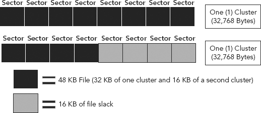
So, a file size of 48 KB will need two clusters and therefore the use of the FAT. The 48 KB file will occupy 32 KB of the first cluster and only 16 KB of the second. (See Figure 8.21.)
FIGURE 8.21 A 48 KB File Requires More than a Single Cluster
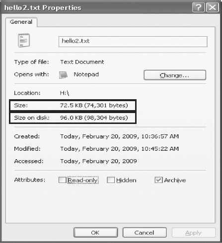
For our continued review of clusters, cluster sizes, and how a cluster’s size is determined, we took our initial example document “hello.txt” and (a) renamed it to “hello2.txt” and (b) increased its size substantially so that it would need more allocated space (e.g., clusters).
If we browse out to the file and right click on the document to view its properties, we see that its physical size of 72.5 KB is now larger than two clusters (64KB) in length. (See Figure 8.22.)
FIGURE 8.22 “hello.txt” Document Showing Larger File Size
How many clusters does this 72.5 KB document need?
1 cluster = 32 KB—not enough space
2 clusters = 64 KB—still not enough space
3 clusters = 96 KB—enough space to hold a 72.5 KB document
So, as a file’s size exceeds one cluster, the FAT automatically allocates additional clusters for the file to occupy, up to a number of clusters sufficient to hold the entire file. Very rarely will a file’s size be the exact size of a single cluster; this will result in either underutilizing the full, entire cluster or requiring additional clusters.
In either situation, clusters will normally have unused or “leftover” allocated space, not occupied by the file, resulting in both sector and file slack, each of which is of use and value to the cyber forensic investigator.
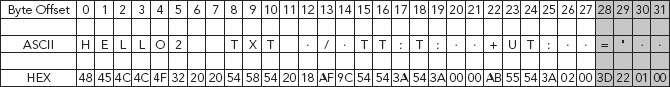
Let us now look at how the directory entries and FAT work together by examining the FAT directory entry for “hello2.txt” (see Figure 8.23).
FIGURE 8.23 FAT Directory Entry for “hello2.txt”
Step 1: Determine Where the File Begins
Q: Why or how does the OS know to go to byte offset 26–27 to determine where the file begins? Why not byte offset 12–13?
A: As we have previously explained, the decision rest in the specific code contained within the OS.
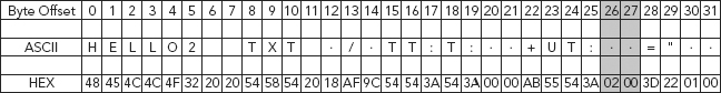
The HEX value at byte offset 26–27, in little endian, remember, is HEX 00 02, which equals the decimal value of 2. Thus, this file begins in cluster 2. From this information provided in the directory entry, the system is able to determine that the file begins at cluster 2. (See Figure 8.24.)
FIGURE 8.24 Byte Offset 26–27—Start of “hello2.txt” at Cluster Two
Step 2: Determine the File’s Size
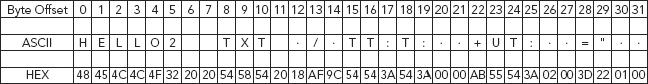
Byte offset 28–31 contains the size of the file in bytes. (See Figure 8.25.)
FIGURE 8.25 Byte Offset 28–31 Contains the Size of the File in Bytes
Step 3: Determine the Number of Clusters Needed
From our previous discussions on how to determine the necessary cluster size, we know that:
1 cluster = 32 KB—not enough space
2 clusters = 64 KB—still not enough space
3 clusters = 96 KB—is ample enough space to hold a 74KB document.
So, the directory entry tells the system the following information about our example file “hello.txt”:
1. Where the file starts.
2. The file’s size in bytes.
3. How many clusters to expect (three).
Step 4: Determine Where the File Ends
As we just discussed, with a FAT 16 filing system each cluster is represented by a 16-bit value in the FAT. See Figure 8.26 for a HEX view of the FAT.
FIGURE 8.26 HEX View of the FAT
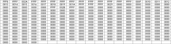
The beginning of the FAT contains two special entries, FFF8 and FFFF, reserving clusters 0 and 1. (See Figure 8.27.)
FIGURE 8.27 Beginning of FAT Reserved Clusters 0 and 1
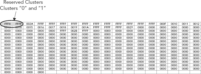
The first cluster available for files is cluster 2. Remember, byte offset 26 and 27 of the directory entry identifies the starting cluster of a file. In our example, “hello2.txt,” the starting cluster is 2, which is actually at byte offset 3. (See Figure 8.28.)
FIGURE 8.28 Cluster 2 at Byte Offset 3—First Cluster Available for Files
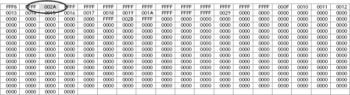
Using a HEX editor and combining the eight-bit HEX characters into pairs, we can more easily visualize each cluster. The first FAT sector (FAT 1), and the third 16-bit HEX character offset is selected here, as shown in Figure 8.28.
The value HEX 002A (or simply HEX 2A) is converted to its decimal equivalent, which equals the value 42. The next piece of this file (“hello2.txt”), since it has exceeded the 32 KB cluster size, is located in cluster 42. Move to sector 42 (offset 43), and we find HEX value is 002B. (See Figure 8.29.)
FIGURE 8.29 Cluster Continuation at Cluster 42 (offset 43)
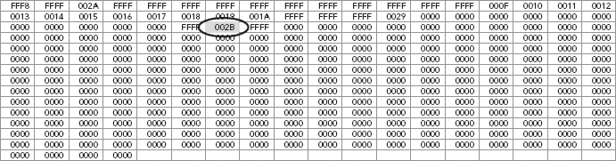
At byte offset 43, we find the HEX value 002B, and converting this HEX value to its decimal equivalent results in the value of 43. This tells us that the file continues onto cluster 43 (offset 44), one over from cluster 42, at byte offset 43. (See Figure 8.30.)
FIGURE 8.30 Cluster Continuation at Cluster 43 (offset 44)

Cluster 44 is one over and we see it has a HEX value of FFFF. Once again, converting Hex FFFF into its decimal equivalent yields a value of 65,535. Any value greater than FFF8 (decimal 65,528) is interpreted as the end of the file. Given that the value in cluster 44 is 65,535, which is greater than 65,528, this is an indication that the end of the file has been reached.
Notice how in our example the file “hello2.txt” is not held (or stored) contiguously upon (across) the hard drive, but instead the file starts in cluster two (2) and skips 40 clusters to cluster 42, and then the file ends at cluster 43 (see Table 8.5).
TABLE 8.5 Summary of FAT Cluster Values for “hello2.txt”
| FAT Cluster Number | HEX Value | Decimal Equivalent |
| 2 | 002A | 42 |
| 43 | 002B | 43 |
| 43 | FFFF | 65,535 |
Imagine for a moment a really long file such as video. This noncontiguous or fragmented file storage can cause inefficiencies, therefore the need for a defragmentation utility. You may have heard some say “defrag your hard drive.” Essentially, this defragmentation process attempts to put all the clusters into a contiguous or defragmented state.
To decode these four bytes, 3D 22 01 00, as a 32-bit little endian integer, we need to reverse the bytes into 00 01 22 3D, and convert this resulting HEX value into its decimal equivalent. Thus, HEX 00 01 22 3D converted into decimal equals 74,301. Therefore, file size for “hello2.txt” is 74,301 bytes.
The FAT file system has limitations imposed upon it by its various structures; both the FAT and the directory entries pose storage limitations.
FAT Limitations
A FAT 16 file system has 16-bit FAT entries. These 16 bits allow for 65,524 possible outcomes (refer to Appendix 8F: The Power of 2).
How many bytes per sector?
There are 512 bytes per sector.
How many bytes are needed to represent one cluster of a FAT 16 table?
Two bytes or 16 bits (FAT 16). Remember each FAT entry represents one cluster.
How many clusters can be represented by the FAT in one sector?
A total of 256 clusters, determined by halving the 512 bytes per sector, because it takes two bytes to represent one cluster, so 256 clusters can be represented by the FAT in one sector.
How many sectors would the FAT need to track its’ potential maximum size?
In order to answer we first need to know what is the maximum size for FAT 16 filing system and how is this determined?
As we have discussed, the maximum potential size of a FAT 16 filing system is 65,536 clusters (really less due to some reserved space, but for our purposes here we will stay with 65,536 clusters). This is its size limitation. Notice this is a cluster limitation, not a byte limitation. The total clusters possible with the FAT 16 file system equals 65,536.
Thus, there are 65,536 clusters total, each needing a unique two-byte entry in the FAT; therefore, only 256 clusters are able to be represented per sector, found by dividing the total number of clusters (65,536 by 256), giving us the number of clusters per sector of 256. Summarizing, 256 sectors are needed to be allocated to the FAT in order to contain the total possible clusters available with a 16-bit file system like FAT 16.
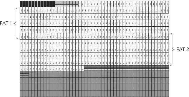
Figure 8.31 depicts a graphical view of the three components of the FAT file system, in addition to identifying two types of “space” found on all disks, wasted space along with allocated space.
FIGURE 8.31 Three Components of the FAT File System
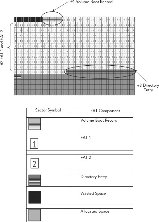
The legend associated with Figure 8.31 identifies the three components of the FAT, as well as the other areas typically found in the registry.
Note: This is a logical representation of the physical construct on the hard drive. This is only a logical interpretation based on actual physical characteristics of a FAT 16 volume, made by a popular forensic software tool, EnCase by Guidance Software.
FAT Summary
1. Each square represents a single sector or 512 bytes.
2. There are two FATs—for redundancy purposes; they are identical.
3. Each FAT is, as we calculated, 256 sectors long.
4. 256 sectors multiplied by 512 (bytes per sector) equals a FAT of 131,072 bytes.
5. Remember that it takes two bytes to represent one cluster; thus, 131,072 bytes/2 equals 65,536 total possible clusters.
6. Really there are only 65,524 possible clusters, taking into account system reserved clusters.
As we have previously discussed, the FAT imposes limitations on the FAT filing system; with FAT 16 for example only 65,536 clusters are possible. The directory entry poses limitations of its own. Remember from our earlier discussion of the directory entry (FAT 12/16), each entry is 32 bytes in length. The total number of directory entries available is determined when volume is formatted and is fixed at 32 sectors within FAT 12/16.
Remember, one sector contains 512 bytes, one directory entry consists of 32 bytes, and the total sectors reserved for directory entries (in FAT 16 file system) equals 32 sectors. The total number of directory entries is determined as follows:
1. Total sectors reserved for all directory entries equals 32, multiplied by 512 (bytes per sector), which equals 16,384 bytes.
2. Total directory entries therefore is determined by taking the 16,384 (total bytes reserved for directory entries) and dividing that value by 32 (bytes per directory entry), yielding a total of 512 directory entries.
Alternatively, the total directory entries can be determined as such:
How many directory entries are there per sector?
512 (bytes per sector) divide by 32 (bytes per single directory entry) equaling 16 directory entries per sector.
How many total possible directory entries?
16 (directory entries per sector) multiplied by 32 (total sectors assigned for directory entries) equals 512 possible directory entries.
Thus, the limitations of FAT 16! Only 512 directory entries or potential files can be saved regardless of the file’s size. FAT 16 would quickly meet its limitations, if not with available storage space in general then in the number of files that could be saved/stored.
Several key concepts of the FAT filing system have been matched with a corresponding analogous companion in Table 8.6.
TABLE 8.6 Library to FAT Comparison
| Library Allegory | File Allocation Table |
| Library | Partition |
| Card catalog | Filing system |
| Dewey Decimal System | Filing system type (i.e., FAT 12/16) |
| Card catalog data | Directory entry data |
| Book shelving | FAT |
| Books | Files |
We have gone into great detail and discussed at length the FAT filing system, not so much to get an in-depth understanding of a more or less obsolete filing system, but in order to gain a better understanding of filing systems in general. Also, using the FAT filing system as a backdrop helps explain many important concepts such as allocated space, slack space, endianness, and bit reordering. These concepts are essential in understanding how data is overwritten in the normal saving, deleting, and general processing of information.
Some of these concepts have previously been touched upon, but the discussion here of the FAT filing system brings these critical concepts together. Will understanding the intricacies of FAT be relevant in an investigation? Perhaps and perhaps not, but understanding slack space and allocated space is of extreme importance.
Understanding that a file system exists and having an idea of how file systems operate in general is critical to understanding how data is accessed, stored, changed, deleted, and/or overwritten. Without an understanding of filing systems, how can we understand how a file is deleted, or perhaps more succinctly put, not deleted? When a file is deleted, we discussed how only the first byte within the directory entry is changed to a tilde “~,” making that space available for future use, or “unallocated.”
However, the rest of the directory entry and the entirety of the file, as demarcated in the FAT, remain. The space is unallocated and ready to be overwritten, but the unallocated and potentially incriminating data remains. These are basic forensic concepts, but some of the most critical and important to grasp!
APPENDIX 8A: PARTITION TABLE FIELDS
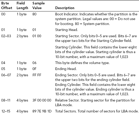
Partition or Volume Type (Offset 4)
01 12-bit FAT primary partition or logical drive.
04 16-bit FAT primary partition or logical drive.
05 Extended partition.
06 32-bit FAT primary partition or logical drive.
07 NTFS primary partition or logical drive.
APPENDIX 8B: FILE ALLOCATION TABLE VALUES
Each 16-bit character in the table of a FAT 16 file system will represent one cluster.
Each 3-bit character in the table of a FAT 32 file system will represent one cluster.
Those values present within the table are as follows:
Unallocated—represented by 0.
Allocated—value will be represented by the next cluster used by the file.
Last Allocated—the last cluster used by the file.
Usually seen with “End Of File” HEX values of Fs.
Although this is not always the case, the rules are:
- FAT 12—a HEX value greater than HEX value FF8 (12 bit)
- FAT 16—a HEX value greater than HEX value FF F8 (16 bit)
- FAT 32—a HEX value greater than HEX value FF FF FF F8 (32 bit)
Bad cluster—seen with a HEX value ending in F7:
- FAT 12—FF7
- FAT16—FF F8
- FAT32—FF FF FF F7
APPENDIX 8C: DIRECTORY ENTRY BYTE OFFSET DESCRIPTION
| 0 | First character of the file name or status byte. |
| 1–7 | File name continued. |
| 8–10 | Three-character file extension. |
| 11 | Attributes—read only, hidden, and so on. |
| 12–13 | Reserved. |
| 14–17 | Create time and date of file stored as MS-DOS 32-bit timestamp. |
| 18–19 | Last accessed, no time. |
| 20–21 | Two high bytes of FAT 32 starting cluster; FAT 12/16 will have zeros. |
| 22–25 | Last written time and date of file again as MS-DOS 32-bit. |
| 26–27 | Starting cluster for FAT 12/16; two low bytes of the starting cluster for FAT 32. |
| 28–31 | Size in bytes of the file. Will be 0 for directories. |
APPENDIX 8D: FAT 12/16 BYTE OFFSET VALUESa
| 0–2 | At this offset we have assembly jump instruction to bootstrap the code. It is usually 0xEB3C90 or 0xEB5890. |
| 3–10 | Offsets from 3–10 contain the OEM id. The OEM id is a string of characters that identifies the name and version number of the operating system that formatted the volume. Some examples of OEM id for different OS versions are: Win95 = MSWIN4.0 Win98 = MSWIN4.1 Win2K / XP = MSDOS5.0 |
| 11–12 | Bytes per sector. The number of bytes per sector by default is 512, but it can be 1,024, 2,048, or 4,096. As we can see in the figure, the HEX value of 11–12 is 00 02. Needs to be viewed in little endian. |
| 13 | Sectors per cluster. It’s necessary to have these values in powers of 2 and should always be greater than zero. |
| 14–15 | Number of sectors in the reserved area. Fat 12/16 is typically one. |
| 16 | Number of FAT tables present. Typically two with FAT 1 and FAT 2. FAT 2 is a duplicate of FAT 1 used for redundancy when FAT 1 is corrupted. |
| 17–18 | Maximum number of 32-byte directory entries in the root directory. It is usually 0 for FAT 32 and 512 for FAT 12/FAT 16. |
| 19–20 | 16-bit integer describing the number of sectors in the partition. If 0, the number of sectors exceeds 65,536. If so, the value is then reflected in byte offset 32–35, a 32-bit integer describing the number of sectors in a partition. |
| 21 | Media descriptor which tells whether it is a removable media or nonremovable media. If the value is 0xF8, then it is nonremovable media. If it is 0xF0, then it is removable media. |
| 22–23 | 16-bit integer describing the number of sectors used by each FAT in FAT 12/FAT 16. Value is zero for FAT 32. |
| 24–25 | Sectors per track value. It is usually 63 for hard disk. |
| 26–27 | Number of heads value. It is typically 255 for hard disk. |
| 28–31 | Number of hidden sectors before the start of the partition. Its value is typically 63 for the first volume on a hard disk. |
| 32–35 | 32-bit integer describing the number of sectors in the partition. If 0, the number does not exceed 65,536 and is described as a 16–bit integer in bytes 19–20. Only one of the two (19–20 or 32–35), and not both, must be set to 0. |
| 36 | Interrupt drive number; HEX 00 for floppies and HEX 80 for hard drives. |
| 37 | Only used by Windows NT; typically set to 0. |
| 38 | Extended boot signature to determine the validity of the three fields that follow. If HEX 29, the next three fields are present and valid, otherwise expect HEX 00. |
| 39–42 | Volume serial number. |
| 43–53 | Volume label in ASCII. This is the label that is given to the user optionally when the volume is created. |
| 54–61 | File system type at time of formatting. Shown are ASCII as FAT 12, FAT 16. |
| 62–509 | Bootstrap program code and error messages. |
| 510–511 | Signature value is two bytes and should be HEX 55AA. |
APPENDIX 8E: FAT 32 BYTE OFFSET VALUESb
| 0–2 | At this offset we have assembly jump instruction to bootstrap the code. It is usually 0xEB3C90 or 0xEB5890. |
| 3–10 | Offsets from 3–10 contain the OEM id. The OEM id is a string of characters that identifies the name and version number of the operating system that formatted the volume. Some examples of OEM id for different OS versions are: Win95 = MSWIN4.0 Win98 = MSWIN4.1 Win2K / XP = MSDOS5.0 |
| 11–12 | Bytes per sector. Number of bytes per sector by default is 512, but it can be 1,024, 2,048, or 4,096. As we can see in the figure, the HEX value of 11–12 is 00 02. Needs to be viewed in little endian. |
| 13 | Sectors per cluster. It’s necessary to have these values in power of two and should always be greater than zero. |
| 14–15 | Number of sectors in the reserved area. Fat 12/16 is typically one. |
| 16 | Number of FAT tables present. Typically two with FAT 1 and FAT 2. FAT 2 is a duplicate of FAT 1 used for redundancy when FAT 1 is corrupted. |
| 17–18 | Maximum number of 32 byte directory entries in the root directory. It is usually 0 for FAT 32 and 512 for FAT 12/FAT 16. |
| 19–20 | 16 bit integer describing the number of sectors in the partition. If 0, the number of sectors exceeds 65,536. If so, the value is then reflected in byte offset 32–35, a 32-bit integer describing the number of sectors in a partition. |
| 21 | Media descriptor which tells weather it is a removable media or non removable media. If the value is 0xF8, then it is nonremovable media. If it is 0xF0 then it is removable media. |
| 22–23 | 16-bit integer describing the number of sectors used by each FAT in FAT 12/FAT 16. Value is zero for FAT 32. |
| 24–25 | Sectors per track value. It is usually 63 for hard disk. |
| 26–27 | Number of heads value. It is typically 255 for hard disk. |
| 28–31 | Number of hidden sectors before the start of the partition. Its value is typically 63 for the first volume on a hard disk. |
| 32–35 | 32-bit integer describing the number of sectors in the partition. If 0, the number does not exceed 65,536 and is described as a 16-bit integer in bytes 19–20. Only one of the two (19–20 or 32–35), and not both, must be set to 0. |
| 36–39 | 32-bit integer which describes the number of sectors used by one FAT (FAT 1/FAT 2) on FAT 32 partition. Bytes 22–23 must be set to 0 for FAT 32. |
| 40–41 | A series of values used to describe if the FAT entries are duplicated. If the value is 0 then the FAT is duplicated. If the value is not zero then duplication does not occur. |
| 42–43 | The major and minor version numbers of the FAT 32 volume. Usually the values are 0×00 and 0×00 meaning the major number and the minor number of FAT is 0. |
| 44–47 | Cluster number where the root directory begins, which is usually 2. Cluster 2 starts immediately after mirror copy of FAT 1, FAT 2 ends. |
| 48–49 | Sector number where FSINFO (File System Information) is found. It is generally located at sector 1 and the backup of FSINFO is found at sector 7. FSINFO purpose is to provide information to the Operating System about the number of free clusters available to the system and the location of the next free cluster. |
| 50–51 | Sector number for the location of backup boot sector, usually sector 6. |
| 52–63 | Reserved, currently not in use. |
| 64 | Interrupt driver number. It is HEX 00 for floppies and HEX 80 for hard drives. |
| 65 | Not used by any version of windows except for Windows NT. Typically set to 0. |
| 66 | Extended boot signature to determine the validity of the three fields that follow. If HEX 0×29, the next three fields (serial number, volume label, file system type) are present and valid. If it is 0×00, then none is available. |
| 67–70 | Volume serial number. Every volume has got a serial number which can be seen by using the “vol” command in DOS. |
| 71–81 | Volume label in ASCII. If none is give by user then it should show “NO NAME.” |
| 82–89 | File system type at time of formatting. This is of no use after formatting and can be changed to any arbitrary value. |
| 90–509 | Boot strap program code and error messages. |
| 510–511 | Signature value; it is of two bytes and should be 0×55AA. |
2^0 = 1
2^1 = 2
2^2 = 4
2^3 = 8
2^4 = 16
2^5 = 32
2^6 = 64
2^7 = 128
2^8 = 256
2^9 = 512
2^10 = 1,024
2^11 = 2,048
2^12 = 4,096
2^13 = 8,192
2^14 = 16,384
2^15 = 32,768
2^16 = 65,536
2^17 = 131,072
2^18 = 262,144
2^19 = 524,288
2^20 = 1,048,576
2^21 = 2,097,152
2^22 = 4,194,304
2^23 = 8,388,608
2^24 = 16,777,216
2^25 = 33,554,432
2^26 = 67,108,864
2^27 = 134,217,728
2^28 = 268,435,456
2^29 = 536,870,912
2^30 = 1,073,741,824
2^31 = 2,147,483,648
2^32 = 4,294,967,296
2^33 = 8,589,934,592
2^34 = 17,179,869,184
2^35 = 34,359,738,368
2^36 = 68,719,476,736
2^37 = 137,438,953,472
2^38 = 274,877,906,944
2^39 = 549,755,813,888
2^40 = 1,099,511,627,776
2^41 = 2,199,023,255,552
2^42 = 4,398,046,511,104
2^43 = 8,796,093,022,208
2^44 = 17,592,186,044,416
2^45 = 35,184,372,088,832
2^46 = 70,368,744,177,664
2^47 = 140,737,488,355,328
2^48 = 281,474,976,710,656
2^49 = 562,949,953,421,312
2^50 = 1,125,899,906,842,620
2^51 = 2,251,799,813,685,250
2^52 = 4,503,599,627,370,500
2^53 = 9,007,199,254,740,990
2^54 = 18,014,398,509,482,000
2^55 = 36,028,797,018,964,000
2^56 = 72,057,594,037,927,900
2^57 = 144,115,188,075,856,000
2^58 = 288,230,376,151,712,000
2^59 = 576,460,752,303,423,000
2^60 = 1,152,921,504,606,850,000
2^61 = 2,305,843,009,213,690,000
2^62 = 4,611,686,018,427,390,000
2^63 = 9,223,372,036,854,780,000
2^64 = 18,446,744,073,709,600,000
2^65 = 36,893,488,147,419,100,000
2^66 = 73,786,976,294,838,200,000
2^67 = 147,573,952,589,676,000,000
2^68 = 295,147,905,179,353,000,000
2^69 = 590,295,810,358,706,000,000
2^70 = 1,180,591,620,717,410,000,000
2^71 = 2,361,183,241,434,820,000,000
2^72 = 4,722,366,482,869,650,000,000
2^73 = 9,444,732,965,739,290,000,000
2^74 = 18,889,465,931,478,600,000,000
2^75 = 37,778,931,862,957,200,000,000
2^76 = 75,557,863,725,914,300,000,000
2^77 = 151,115,727,451,829,000,000,000
2^78 = 302,231,454,903,657,000,000,000
2^79 = 604,462,909,807,315,000,000,000
2^80 = 1,208,925,819,614,630,000,000,000
2^81 = 2,417,851,639,229,260,000,000,000
2^82 = 4,835,703,278,458,520,000,000,000
2^83 = 9,671,406,556,917,030,000,000,000
2^84 = 1.93E+25
2^85 = 3.87E+25
2^86 = 7.74E+25
2^87 = 1.55E+26
2^88 = 3.09E+26
2^89 = 6.19E+26
2^90 = 1.24E+27
2^91 = 2.48E+27
2^92 = 4.95E+27
2^93 = 9.90E+27
2^94 = 1.98E+28
2^95 = 3.96E+28
2^96 = 7.92E+28
2^97 = 1.58E+29
2^98 = 3.17E+29
2^99 = 6.34E+29
2^100 = 1.27E+30
2^101 = 2.54E+30
2^102 = 5.07E+30
2^103 = 1.01E+31
2^104 = 2.03E+31
2^105 = 4.06E+31
2^106 = 8.11E+31
2^107 = 1.62E+32
2^108 = 3.25E+32
2^109 = 6.49E+32
2^110 = 1.30E+33
2^111 = 2.60E+33
2^112 = 5.19E+33
2^113 = 1.04E+34
2^114 = 2.08E+34
2^115 = 4.15E+34
2^116 = 8.31E+34
2^117 = 1.66E+35
2^118 = 3.32E+35
2^119 = 6.65E+35
2^120 = 1.33E+36
2^121 = 2.66E+36
2^122 = 5.32E+36
2^123 = 1.06E+37
2^124 = 2.13E+37
2^125 = 4.25E+37
2^126 = 8.51E+37
2^127 = 1.70E+38
2^128 = 3.40E+38
340,282,366,920,938,000,000,000,000,000,000,000,000
a Steve Bunting and William Wei, The Official EnCE EnCase Certified Examiner Study Guide (Indianapolis: John Wiley & Sons, 2006).
b Bunting and William Wei, The Official EnCE EnCase Certified Examiner Study Guide (Indianapolis: John Wiley & Sons, 2006).