
Chapter 8
More NVF: NSX Edge Services Gateway
Breaking down the name, Edge Services Gateway (ESG), you get a few clues about what it does and how it fits in your NSX design. The word edge implies location, the boundary of our network. The ESG sits on that edge between the virtual NSX network and the physical network. The term gateway is an older word for router. In the preceding chapter, we focused on the routing function provided by the ESG. The ESG routes traffic in and out of the NSX environment. It is the gateway that NSX uses to forward traffic to a physical router.
The focus here will be on services: the network services provided by the ESG. In addition to routing, the ESG provides several L3‐L7 services including NAT, load balancer, firewall, VPNs, DHCP, DHCP relay, and DNS forwarding. You'll recall that the ESG is an appliance and not part of the distributed topology. This means that to use these ESG services, the data is going through a virtual machine (VM).
ESG Network Placement
Services can be used in combination or an ESG can be dedicated to provide a single service, such as load balancer, and do nothing else.
In terms of network placement and design, you can create as many ESGs as you need, up to 250 per host and up to 2,000 per NSX Manager. The flexibility in having a VM form factor means that you can create dedicated ESGs to provide services for specific applications. Once the application is no longer necessary, the ESG can be removed with it as well. VMware's recommendation is to place all ESGs in an edge cluster so that all North‐South (N‐S) traffic goes through one cluster (see Figure 8.1).
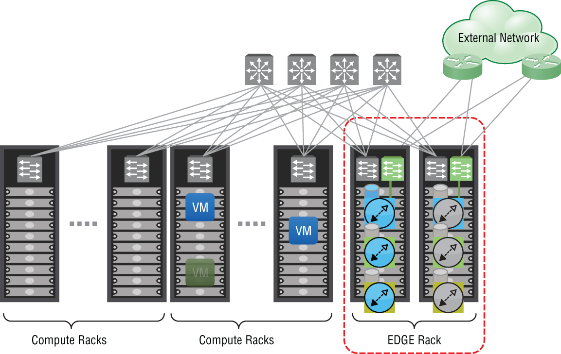
FIGURE 8.1 Separating edge services from compute
Network Address Translation
The first ESG service we will examine is Network Address Translation (NAT). NAT is most commonly used to map private and public IP addresses. For example, a VM with the address 10.20.6.21 needs to send traffic to the Internet server 8.8.8.8 (see Figure 8.2). Without NAT, the packet isn't routable outside the organization because the source address, 10.20.6.21, falls within the private address range outlined in RFC 1918. With NAT, we can translate the source address, 10.20.6.21, to one that's publicly routable. When the external server responds, NAT will translate the public address within that packet back to 10.20.6.21 so that it can be routed to the correct VM.

FIGURE 8.2 ESG providing Network Address Translation
The ESG supports two types of NAT. Your choice depends on what you are trying to change: the source or destination address. If you're somewhat familiar with NAT, Source NAT (SNAT) is probably what first comes to mind. As we go through the steps to configure SNAT next, focus on what happens to the source address.
Configuring Source NAT
In an earlier example, the source, 10.20.6.21, was trying to initiate a conversation with the destination, 8.8.8.8:
- When the packet leaves the VM, we would see exactly that:
S=10.20.6.21 D=8.8.8.8 - The packet goes through the ESG, which is performing Source NAT.
Let's say it is configured to translate 10.20.6.21 to 50.1.8.21. The readdressed packet leaving the ESG and bound for the physical router would look like this:
S=50.1.1.21 D=8.8.8.8 - The packet is routed to the 8.8.8.8 server.
- When the server responds, the packet's source and destination are now flipped, since the server would now be the one sending (the source) and the VM would be the one receiving (the destination):
S=8.8.8.8 D=50.1.1.21 - The packet is eventually routed to the ESG.
- The ESG would then translate the destination address back to its original (the address of the VM):
S=8.8.8.8 D=10.20.6.21
Note that in every step, the address 8.8.8.8 was never translated. It was only the original source address, 10.20.6.21, that was translated to 50.1.1.21 and then back again to 10.20.6.21. With Source NAT, it translates the original source address.
Configuring Destination NAT
The second type of NAT we can implement on the ESG is Destination NAT (DNAT). It is used to translate the destination address. Before getting into the details, let's clear something up that's often confused. In the previous example, two translations took place: when the packet was going outbound, it translated the original source address (from 10.20.6.21 to 50.1.1.21), and on the return response, it translated the destination address (from 50.1.1.21 to 10.20.6.21). Even through a destination address was translated here, this is not an example of DNAT; it's entirely Source NAT. So, how is DNAT different? It's all about which side initiates the conversation.
Let's look at the previous SNAT example again. It allows the device on the inside (in our example, the VM) to initiate a connection to a device on the outside (server 8.8.8.8). The VM's address is the only one that gets changed going out and coming back. Notice in the previous walkthrough detailing the changes that 8.8.8.8 never changed, regardless of direction. The key takeaways here are that it was initiated by the VM, a device on the inside of our network, and it is the source address (the VM's) that is changed.
Now, let's compare this with DNAT. We will use the same diagram but focus on different devices (see Figure 8.2). For this example, imagine a user on the Internet with the IP 200.1.1.1 wants to connect to our web server, 10.10.1.21. The problem for the user is that the destination is a private address, so without NAT, there's no way for the user to connect to it. The solution is to configure DNAT on the ESG. In the ESG configuration we configure DNAT mapping 10.10.1.21 (the web server's actual address) to 50.1.1.100 (what the user believes the address to be).
This is what the conversation would look like:
- The Internet user (200.1.1.1) sends a packet to 50.1.1.100:
S=200.1.1.1 D=50.1.1.100 - The packet is eventually routed to the ESG. The ESG then translates the destination 50.1.1.1 to the web server's real address, 10.10.1.21:
S=200.1.1.1 D=10.10.1.21 - The web server receives the packet and responds by flipping the source and destination, since the web server is now the source sending the response:
S=10.10.1.21 D=200.1.1.1 - The ESG receives the response, changes the web server's address to 50.1.1.100, and then routes the packet to the user:
S=50.1.1.100 D=200.1.1.1
The key takeaways for this DNAT example are that it was initiated by the user's PC, on a device outside our network, and it is the destination address (the web server's) that is changed.
When deciding which type of NAT to use, ask yourself who is initiating the traffic. If it is being initiated within your network, use SNAT. If it is initiated from outside your network, use DNAT.
In addition to modifying IP addresses, TCP and UDP port numbers can be changed as well. For example, we developed some remote labs for the US Army. The Army was not at all amenable to modifying their outbound firewall to connect to our lab TCP port 23, and suggested we bring the lab gear to the base and re‐rack it there. The whole point of our developing a remotely accessible lab environment was to save the time and cost involved in shipping. Instead of following the Army's suggestion, we solved it with DNAT. Users on base were able to connect remotely over port TCP 80, a port that was allowed by their firewall. We simply added a NAT rule on our side that did two things. It translated our rack private IP address to a public one the Army could route to and translated our actual port, TCP 23, to TCP 80, a port already open on their firewall.
Configuring SNAT on the ESG
Traffic initiated from the NSX environment with a private address needs to be translated using SNAT:
- Within the vSphere Client, go to Menu ➢ Networking And Security ➢ NSX Edges (see Figure 8.3).
- Double‐click the ESG you want to configure, and then select the NAT tab.
- Click + Add and select Add SNAT Rule (see Figure 8.4).
A new panel appears: Add SNAT Rule (see Figure 8.5).
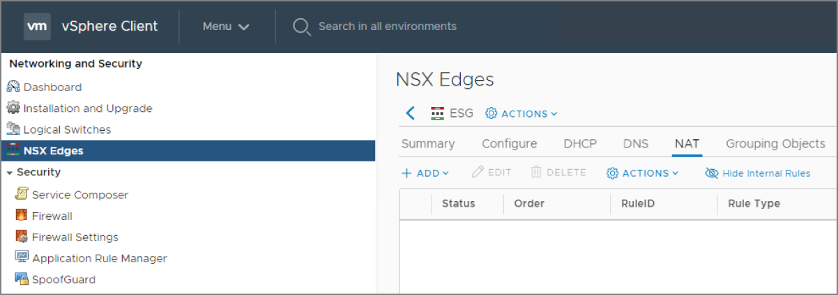
FIGURE 8.3 Configuring NAT on the NSX ESG
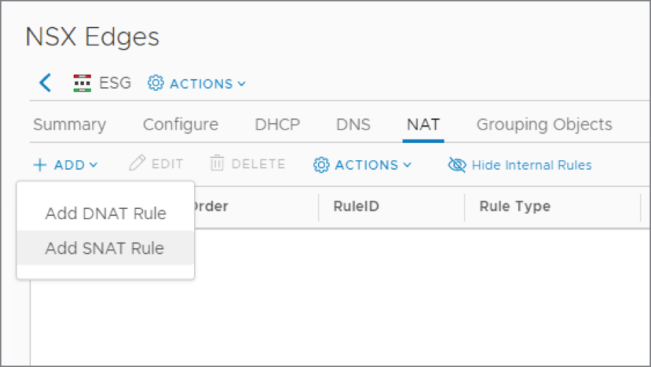
FIGURE 8.4 Adding a Source NAT rule
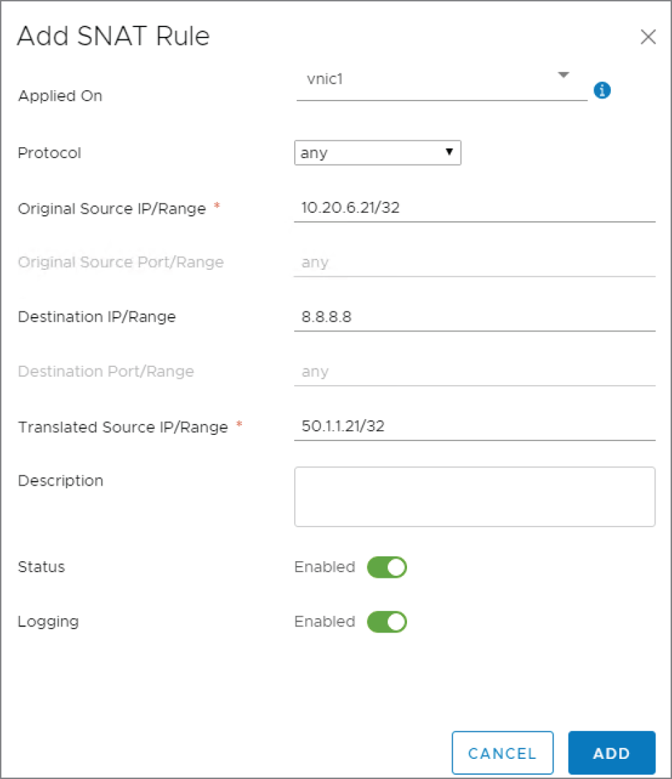
FIGURE 8.5 Configuring the translated address
The following are explanations of the presented options:
- Applied On We want the rule applied to the uplink interface of the ESG.
- Protocol By selecting Any, the fields below for source and destination ports will be grayed out. This is because Any implies matching any port for that IP address. If you wanted to get more granular and selected UDP, for example, the fields would no longer be grayed out and you could enter a port number or a range of ports. Since 8.8.8.8 is a DNS server, we could have alternatively specified UDP 53, which is the port DNS listens on for name resolution requests.
- Original Source IP/Range Here we have chosen to translate the single address, 10.20.6.21. Notice the prefix /32. This essentially says to match on all 32 bits of the IP address. It is not the subnet mask configured on the device. By adding /32, it says that you want to translate this exact address. In contrast, we could have entered 10.20.6.0/24 to translate all of the addresses on the 10.20.6.X subnet.
- Destination IP/Range This specifies that we only want to perform NAT when 10.20.6.21 is sending traffic destined for 8.8.8.8. If 10.20.6.21 attempted to send traffic to 176.32.98.166, no translation would occur.
- Translated Source IP/Range 50.1.1.21 is the exact address (/32) we are translating 10.20.6.21 into.
- Click the Add button.
The NAT configuration is not applied until the rule is published.
- Click the Publish button on the far right (see Figure 8.6).
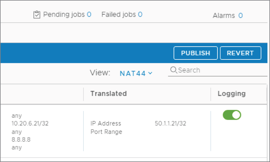
FIGURE 8.6 Publishing the changes
Configuring DNAT on the ESG
When traffic is initiated from outside our network attempting to access a resource like a company web server, for example, we need to configure DNAT. Within the vSphere Client:
- Go to Menu ➢ Networking And Security ➢ NSX Edges.
- Double‐click the ESG you want to configure, and then select the NAT tab.
- Click + Add and select Add DNAT Rule (see Figure 8.7).
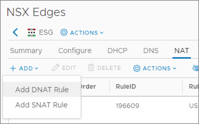
FIGURE 8.7 Adding a Destination NAT rule
A new panel appears: Add DNAT Rule (see Figure 8.8).
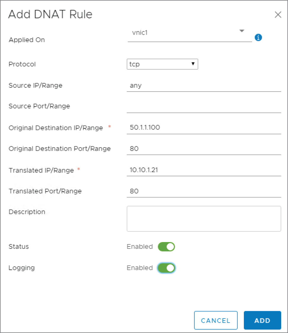
FIGURE 8.8 Configuring the translated address
The following are the available options explained:
- Applied On Again, we want this to be configured on the ESG uplink interface.
- Protocol For this example, let's say that the scenario is to allow anyone from outside our network to be able to reach our web server. According to DNS, the address associated with www.hydra1303.com is 50.1.1.100. However, the actual address configured on the web VM is 10.10.1.21. Since web traffic is TCP based, select TCP for the protocol.
- Source IP/Range Remember, with DNAT, this applies to traffic initiated from outside our network. Instead of entering a single address here, if we want any device on the Internet to be able to access our web server, enter any here.
- Original Destination IP/Range Again, thinking from the perspective of the outside user trying to reach the web server, the destination IP is what they believe it to be, the public address 50.1.1.100.
- Original Destination Port/Range The TCP port the server is listening on is 80. From the user's perspective, the connection is to 50.1.1.100 TCP port 80.
- Translated IP/Range When the packet from the outside user reaches the ESG, we want NAT to translate 50.1.1.100 to 10.10.1.21, the actual address configured on the web server.
- Translated Port/Range We're not doing anything fancy here in translating the ports. They stay the same. We're only translating the destination IP address, so the port remains unchanged at 80.
- Click the Add button, and then click Publish to apply the new rule.
ESG Load Balancer
The ESG load balancer takes incoming traffic and distributes it among multiple servers in a way that is completely transparent to end users. By distributing the traffic load, throughput is maximized, latency is reduced, and overall resource utilization is optimized.
In a nutshell, the way it works is by presenting an external IP address that users from the outside can access. An example might be the public IP used to access a company web server. The load balancer maps this address to a set of internal servers and distributes the load among them. As an admin, you can choose the algorithm that dictates how the traffic will be load balanced. The load can be split based on weighted round‐robin, IP hash, least used connection, and others.
The ESG load balancer is no slouch compared to physical load balancers when it comes to options and features. These include:
- Load balancing up to Layer 7
- High throughput and high connections per second
- IPv6 support
- Health checks (checking connections to hosts, the stability of the host, and any issues overall with the load balancing)
- One‐arm mode (also known as proxy mode)
- Inline mode (also known as transparent mode)
- Connection throttling
- SSL termination and certificate management
- Ability to place individual servers from the load balancing pool in maintenance mode
- HA support for L7 proxy load balancing
- URL rewrite and redirection
- Ability to accept TCP, UDP, FTP, HTTP, and HTTPS requests sent to the external IP address and choose which internal server to forward it to
- Stateful HA
We previously discussed the choices for the size of the ESG, going from Small to X‐Large. If your ESG is performing load balancing, VMware recommends that you use the X‐Large form factor. The size doesn't change what the load balancer is capable of in terms of function, but the extra resources are necessary for high performance throughput and high connections per second.
Comparing the ESG load balancer and a physical load balancer, you'll find them equal in terms of performance. However, when it comes to creating complex context rules, an F5 load balancer will have more granular control options compared to the virtual ESG load balancer.
More than 75 percent of load balancing that companies perform is basic. They require an L3‐L7 high‐performance load balancer that's capable of handling things like SSL terminations and certificate management, but they are not creating complicated context rules. If this is the case for your company, the NSX ESG load balancer is an easy choice.
That's not to say that you can't have a proprietary load balancer in NSX. Rather than trying to beat F5 at its own game, VMware has chosen to partner with them, allowing a virtualized F5 load balancer to be added to the IOChain. If your organization needs the additional functionality that the F5 provides for advanced scripting, it can be easily integrated into NSX. Rather than limiting your options, NSX extends them.
If the ESG load balancer is set to proxy mode, it's deployed on the same subnet as the VMs (see Figure 8.9) and is separate from the router (another ESG). It receives traffic on a virtual IP and then uses NAT to forward the traffic to one of the internal VMs. In this design, the backend servers are not able to see the original client IP address due to NAT.
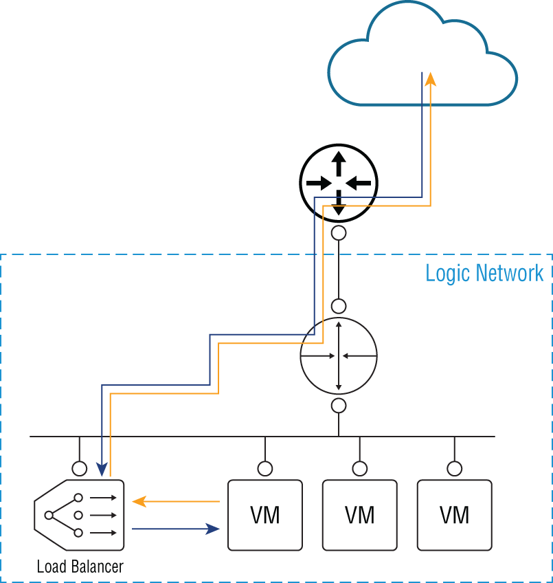
FIGURE 8.9 One‐armed load‐balancing design
If this is an issue and your backend servers require the ability to view the original client addresses, you can use inline mode instead (see Figure 8.10). With inline load balancing, the ESG load balancer is not separate from the ESG router handling North‐South traffic. Instead, both services are provided by the same appliance.
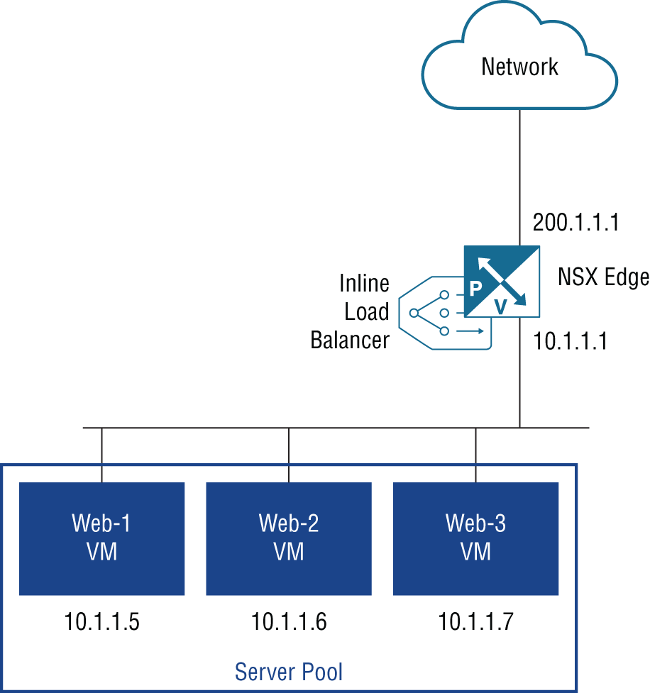
FIGURE 8.10 Inline load‐balancing design
With this design, the virtual IP address receiving user traffic is the one on the ESG's uplink interface (200.1.1.1). The internal interface (10.1.1.1) is what the VMs will use as their default gateway.
Although the ESG load balancer can be configured to load balance based on Layer 4 or Layer 7 information, Layer 4 should be your choice if higher performance is desired. Keep this in mind when configuring the ESG. You select the parameters that will be examined for the load‐balancing decisions. If you happen to choose any of the L7 options, it will load balance at Layer 7.
Configuring an ESG Load Balancer
For this, we will use the standard vSphere Web Client and perform the following steps:
- Go to Home ➢ Networking & Security ➢ NSX Edges (see Figure 8.11).
- Double‐click the ESG you want to configure, and then select the Load Balancer tab (see Figure 8.12).
- With Global Configuration selected on the left, click the Edit button on the far right.
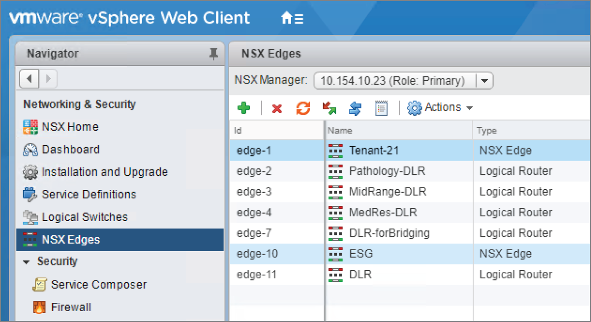
FIGURE 8.11 Selecting the ESG
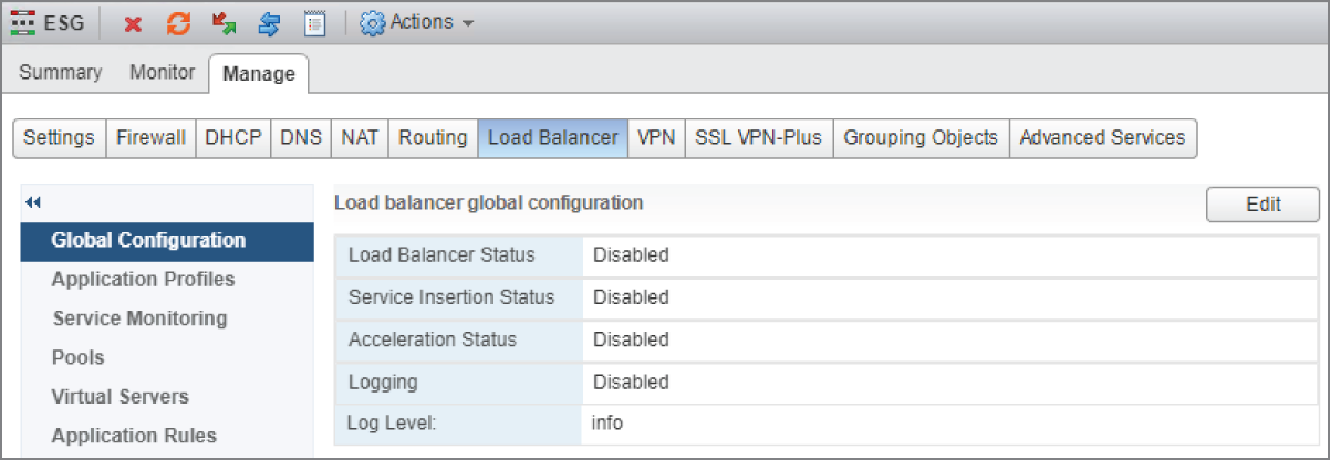
FIGURE 8.12 Load Balancer tab
- Place check marks next to Enable Load Balancer and Enable Acceleration (see
Figure 8.13). Then click OK.
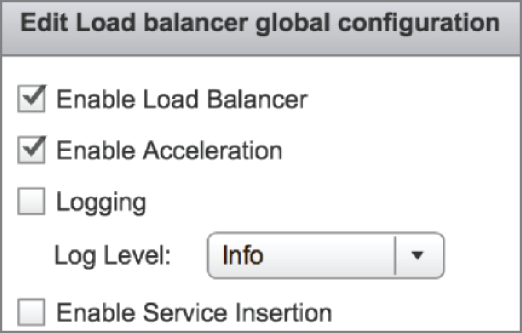
FIGURE 8.13 Enabling the load‐balancer service
- In the left menu, select Pools (see Figure 8.14) and then click the green + sign.
A new panel appears. In the top half of this pane, we will define the load‐balancing method to use for a pool of web servers (see Figure 8.15).
- Give the pool a name and a description.
Here, we are choosing a simple round‐robin method to split the traffic load across the web servers.
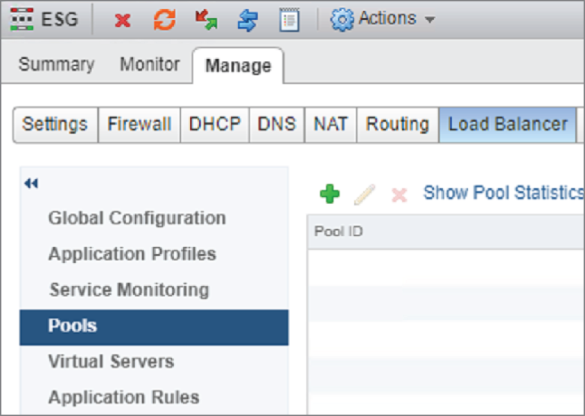
FIGURE 8.14 Creating a pool of servers to load balance across
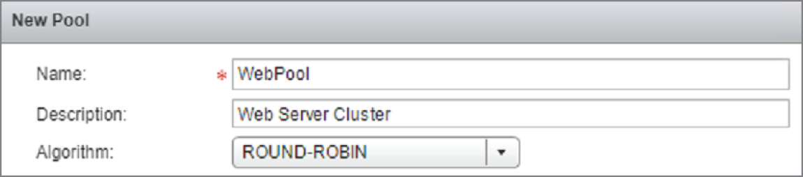
FIGURE 8.15 Selecting the load‐balancing algorithm
In the lower half of the pane, we can define the web servers that will be members of the pool.
- Click the green + sign (see Figure 8.16).
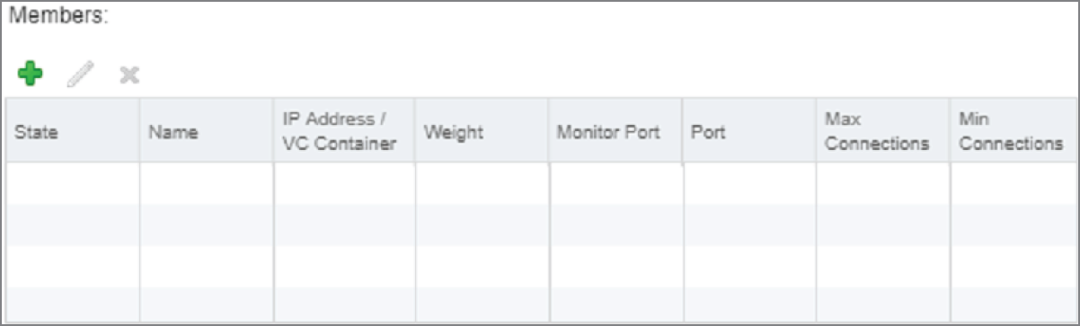
FIGURE 8.16 Adding members to the server pool
Web‐1 10.10.1.21 and Web‐2 10.10.1.22 are the members we wish to add.
- Starting with Web‐1 (see Figure 8.17), enter the name, the IP address, and the web port, 80.
- Click OK and then repeat for Web‐2 10.10.1.22.
- After adding the server members to the pool, change the Monitors drop‐down from NONE to default_http_monitor (see Figure 8.18) and click OK.
- To verify the status of the pool, click the Show Pool Statistics link on the same line as the green + sign (see Figure 8.19).
NSX comes with a preconfigured application profile for web servers. A profile is essentially just a set of parameters indicating how the application should be handled.

FIGURE 8.17 Configuring each member of the pool
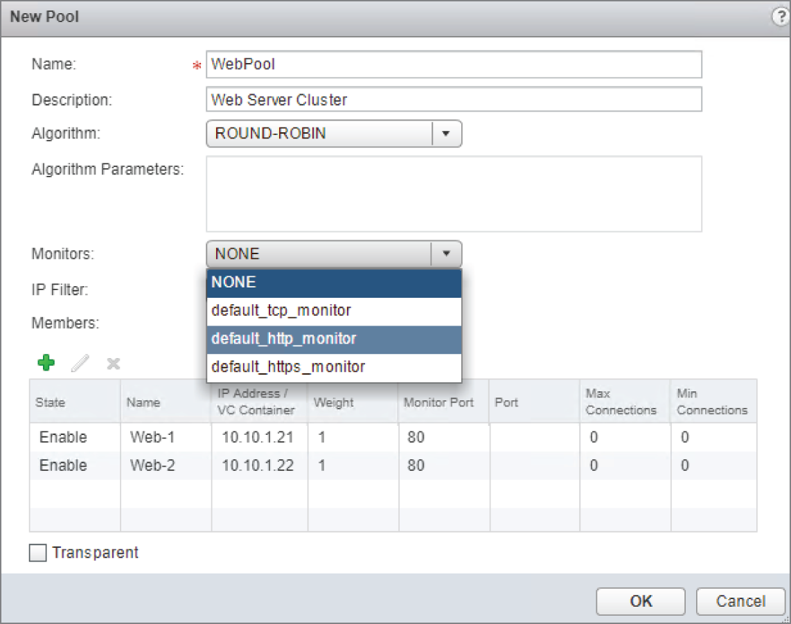
FIGURE 8.18 Selecting the default http monitor for the pool
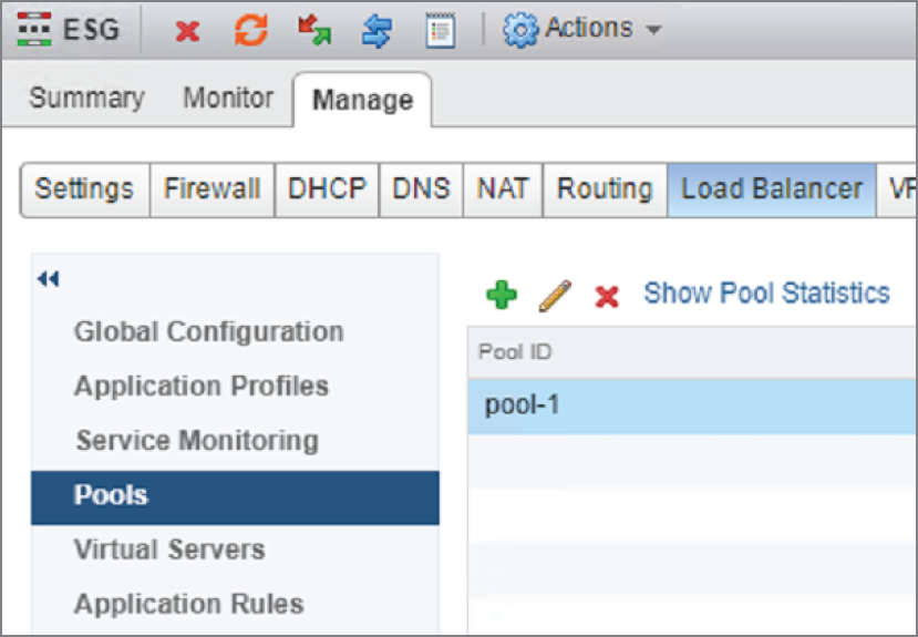
FIGURE 8.19 Verifying the status of the pool
- Select Application Profiles in the menu on the left (see
Figure 8.20) and click the green + sign.

FIGURE 8.20 Load balancer application profiles
A new panel appears: New Profile (see Figure 8.21).

FIGURE 8.21 Selecting a preconfigured application profile
- Enter a name for the profile and select HTTP from the drop‐down. Click OK.
The last step is to create a virtual server. This is where we enter a single IP address that will be used to access the entire pool of web servers.
- Click Virtual Servers in the menu on the left (see Figure 8.22) and then click the green + sign.
A new panel appears: New Virtual Server (see Figure 8.23).
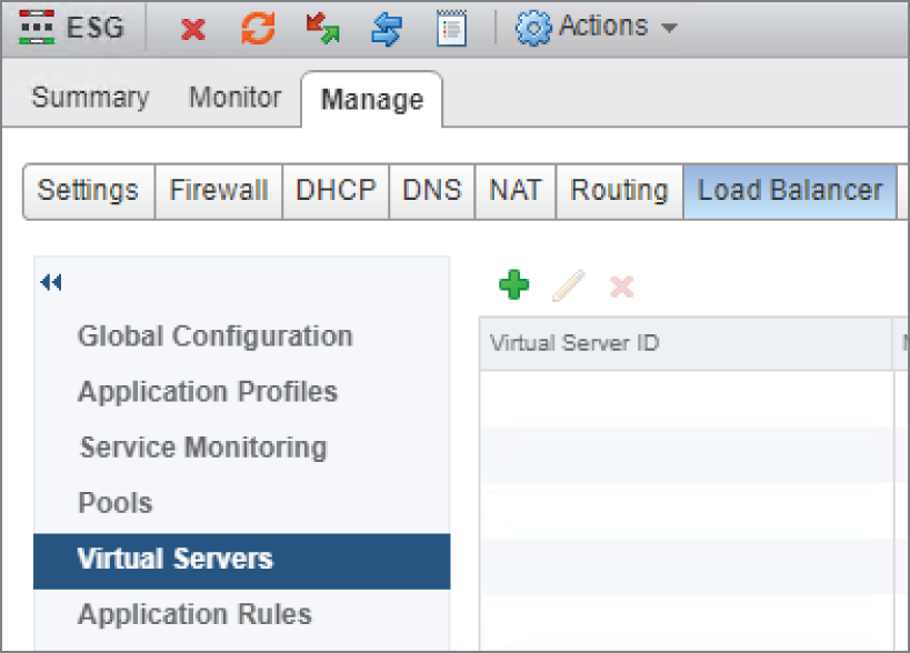
FIGURE 8.22 Creating a virtual server to be the front end
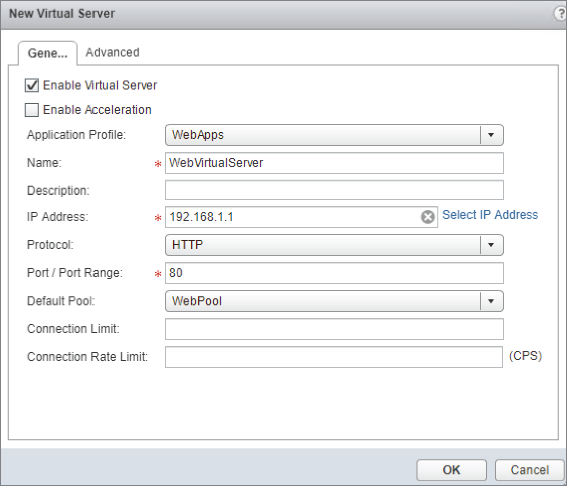
FIGURE 8.23 Selecting an IP address and port number for the virtual server
- Enter a name and IP address for the virtual server (this is an IP address on the ESG) and use the drop‐down to select the pool you created earlier.
Layer 2 VPN (If You Must)
The ESG provides several VPN solutions to fit different use cases. The SSL VPN is a user VPN that allows remote contractors and road warriors to securely connect to network. The site‐to‐site VPN is used to connect multiple data centers or remote sites. There's also the option to create a Layer 2 VPN (L2VPN), which allows you to extend your data center's subnets across geographical boundaries. This provides a simple solution, for example, when trying to migrate a legacy data center to a virtualized NSX data center because it means that IP addresses don't have to change for the migration from A to B. The same broadcast domain (subnet) exists on both sides. The Layer 2 VPN simply ties them together with a tunnel.
Other options exist for migrating. The use of hardware VTEPs on a physical device made by a vendor that has a partnership with VMware is one solution. Another solution would be to create a Layer 2 bridge, an option we previously discussed, that creates a bridge between a VLAN on the physical network and a Logical Switch. Beyond that, we could deploy NSX on both sides and configure Cross‐vCenter NSX with universal logical switching.
Choosing to implement a Layer 2 VPN for our migration strategy over the others won't have the same performance benefits, but it's simpler. It doesn't require changing IP addresses, it doesn't have the cost associated with other solutions, and overall, there's minimal downtime. It all depends on your business requirements. If you need a long‐term solution, this isn't it. But if you are looking for an option that is quick and temporary, consider the L2VPN.
The diagram in Figure 8.24 shows an L2VPN that forms a tunnel connecting the L2 domain 10.1.1.X on the right, the legacy site, with the same L2 domain 10.1.1.X on the left, the NSX domain.
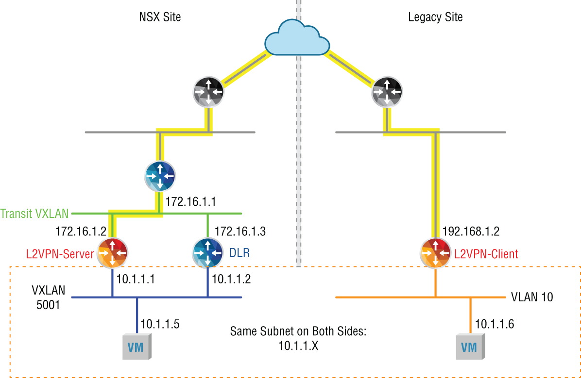
FIGURE 8.24 Implementing an L2VPN as a temporary solution to connect two sites
Secure Sockets Layer Virtual Private Network
Outside users can securely connect to NSX networks that sit behind the ESG using Secure Sockets Layer Virtual Private Network (SSL VPN) (see Figure 8.25). The user can initiate a connection to the ESG and dynamically establish an encrypted tunnel. An SSL tunnel doesn't always require the installation of a VPN client on the user machine. SSL capabilities are built into all modern web browsers; however, using a web browser in place of a standalone VPN client only provides web access mode. If the network resource can be accessed with a web browser interface, there's no need to install a separate VPN client. If full network access is desired, a VPN client must be installed on the user machine.
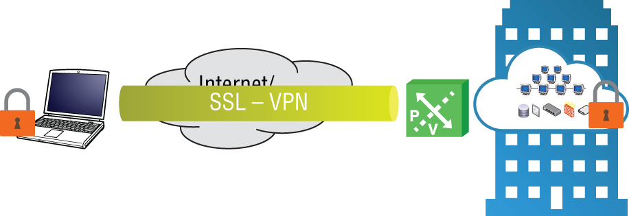
FIGURE 8.25 SSL VPNs allowing remote mobile users to connect
When the initial connection is made to the ESG, the ESG hands the user an IP address from a configured pool of addresses. In addition to the IP pool, the ESG will have a list of networks the user is permitted to access.
Split Tunneling
Let's say that the user is Susan, a nurse working for a health insurance company, who triages patients over the phone when they call the nurse line for advice. The SSL secure tunnel allows Susan to access medical documents located in the corporate data center. When the nurses are on break, they often want to browse the Internet or check personal email. This traffic is not business related, but it consumes corporate resources since it is also being routed through the VPN, the same path used to access the medical documents. An option to prevent non‐business traffic from being routed through the VPN connection is to create a split tunnel. With a split tunnel, the admin can specify that traffic is pushed through the tunnel when the user is accessing resources specifically on the company network. For any other destination, instead of sending that traffic through the tunnel, it is routed normally to their home Internet service provider (ISP) and doesn't take up any resources on the corporate side.
When configuring SSL, we can explicitly define which traffic is to be sent over the tunnel and which should bypass it. However, if you want all of the traffic to first go through the tunnel so that it can be inspected and potentially dropped by the firewall, you have the option to not use split tunneling.
Configuring SSL VPN
Using the standard vSphere Web Client, perform the following steps:
- Go to Home ➢ Networking & Security ➢ NSX Edges.
- Double‐click the ESG you want to configure and select the SSL VPN‐Plus tab (see
Figure 8.26).
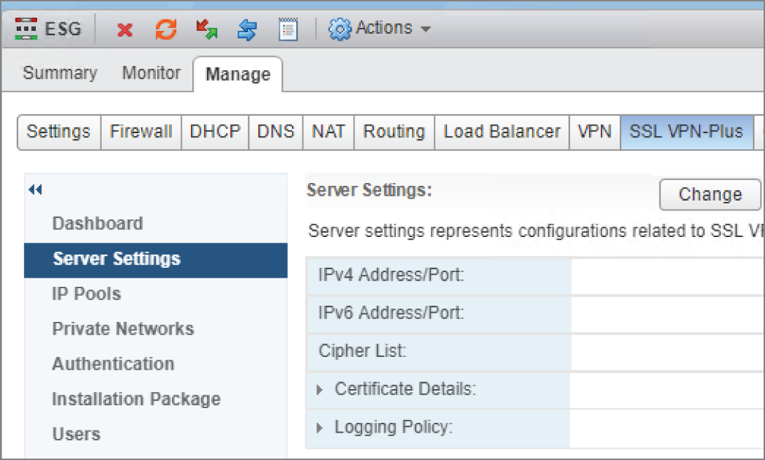
FIGURE 8.26 Configuring the SSL VPN service on the ESG
- Click the Change button to the right of Server Settings.
The Change Server Settings window appears (see Figure 8.27).
- Select an IP address on the ESG that your end users will use to VPN in. The standard port number for SSL is 443. This should already be populated in the Port field.
- Choose an encryption algorithm, and then click OK.

FIGURE 8.27 Choosing the IP address and port users will VPN to
- From the menu on the left, select IP Pools, and then click the green + sign (see
Figure 8.28).
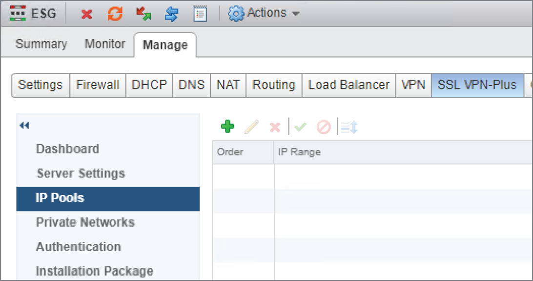
FIGURE 8.28 Creating an IP pool
When a VPN end user connects, they will be assigned an IP address, subnet mask, and default gateway for their end of the VPN tunnel. In this window, we configure a range of addresses so that multiple users can simultaneously connect, each with their own IP address assigned from the pool (see Figure 8.29).
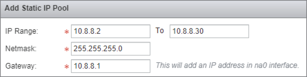
FIGURE 8.29 Configuring a range of addresses to assign to VPN users
- After clicking OK, select Private Networks from the menu on the left and click the green + sign.
This is where we get to specify which networks the VPN user will have access to (see Figure 8.30).
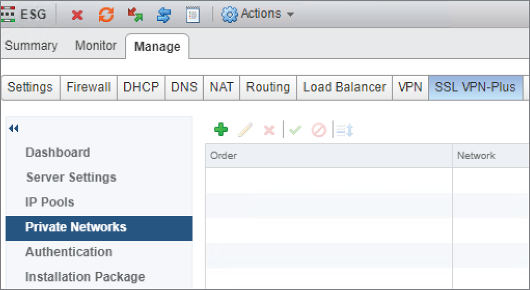
FIGURE 8.30 Selecting which networks the user can access
In this example, we are giving the VPN user access to network 10.30.8.0/24 (see Figure 8.31). We have chosen to send traffic to this destination over the tunnel.
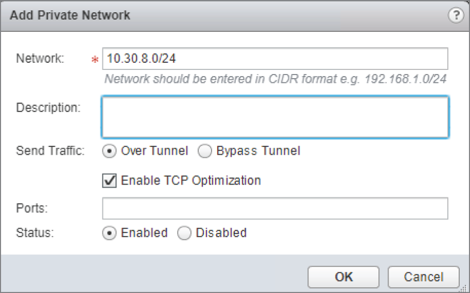
FIGURE 8.31 Enabling TCP optimization when using the tunnel
- To optimize the speed over the tunnel, make sure there is a check mark next to Enable TCP Optimization.
- Click OK, and repeat these steps to grant access to additional private networks.
You can also configure split tunneling here, adding networks that you don't want the user to access via the VPN. Split tunneling doesn't block users from accessing these networks; it simply routes the traffic normally, instead of being routed through the VPN tunnel.
- Select Authentication from the menu on the left, and click the green + sign (see
Figure 8.32).

FIGURE 8.32 Authenticating VPN users
To authenticate users, you can point to an authentication server using Active Directory, LDAP, RADIUS, or RSA‐ACE. Selecting one of these will allow you to enter the IP address of the server. Another option is to simply use local authentication, which we're using in this example (see Figure 8.33).

FIGURE 8.33 Configuring password rules for VPN access
- When selecting local authentication, set the rules for passwords, including length, numbers, special characters, number of retries, etc. After making your choices, click OK.
- Select Installation Package from the menu on the left, and click the green + sign (see
Figure 8.34).
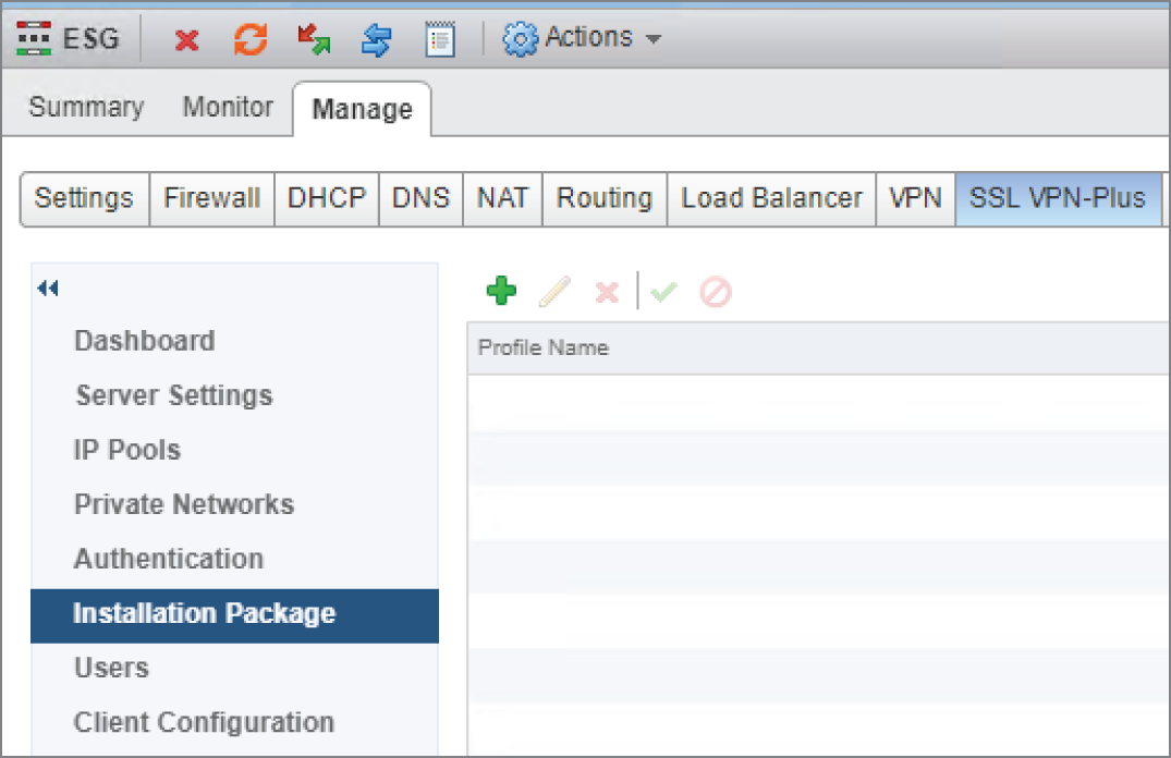
FIGURE 8.34 Creating VPN client installation packages for download
Being an SSL VPN, users can connect using a web browser or a VPN client. When the user connects with a browser, they will see a link to download a client installation package. The Select Installation Package section allows the admin to create VPN client installation packages for Windows, Linux, or Mac.
- Enter a name for the package and click the green + sign to add the public IP address or FQDN of the ESG in the Gateway field (see Figure 8.35).
The SSL port number should match what you configured previously.
Notice the other installation parameters available allowing you to automatically create a desktop icon when the VPN is installed, allow passwords to be remembered, etc.
- After choosing your preferred options, click OK.
- In the left menu, select Users and click the green + sign (see Figure 8.36).
In our example, since we're not using Active Directory or any other authentication server, an option is available here to add VPN user credentials to the local database.
- On the Add User page, fill in the relevant details (see Figure 8.37).
- Click OK.
The last step is to start the SSL VPN service.
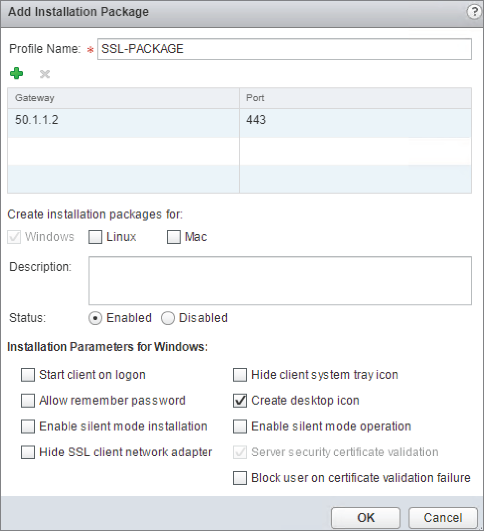
FIGURE 8.35 Creating and customizing packages for different platforms
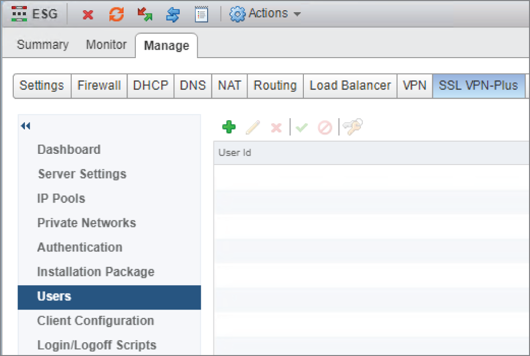
FIGURE 8.36 Creating credentials for VPN users

FIGURE 8.37 Adding a VPN user
- In the left menu, select Dashboard (see
Figure 8.38) and click the Start button.
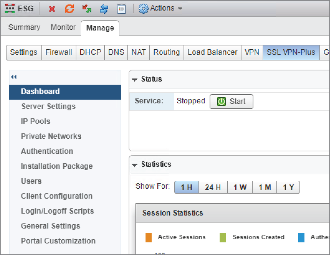
FIGURE 8.38 Starting the SSL VPN service
You will be prompted, “Do you want to start the service?”
- Click Yes, and you're all set.
Internet Protocol Security VPN
To connect an ESG to a remote site, instead of a per‐user SSL VPN, a site‐to‐site, Internet Protocol Security (IPsec) VPN can be created. With a site‐to‐site VPN, there is no need for users to have a VPN client installed to access resources at the remote site. Any traffic bound for the remote site is simply routed into the tunnel (see Figure 8.39).
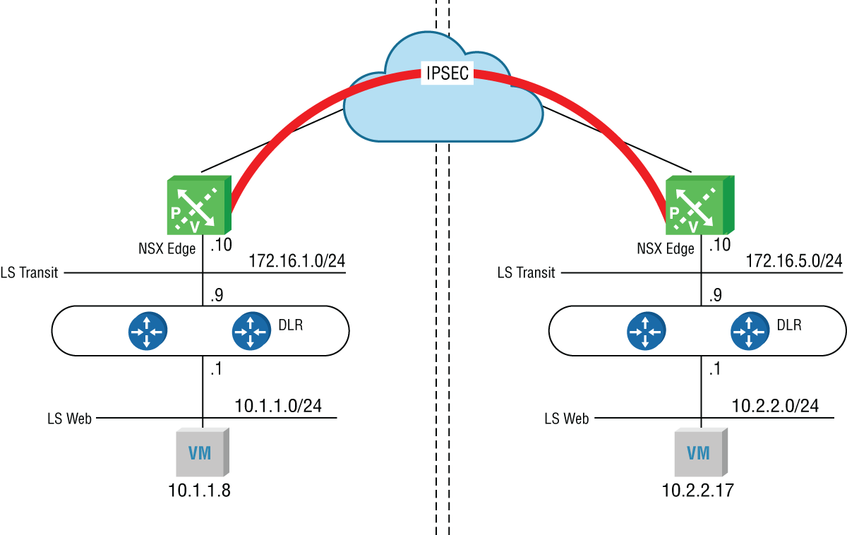
FIGURE 8.39 Site‐to‐site IPsec VPN
A standard IPsec VPN doesn't support multicasting, something dynamic routing protocols typically rely on to exchange information, and it only carries IP traffic. Years ago, Cisco developed a workaround with a new type of tunnel called Generic Routing Encapsulation, or GRE, which eventually became a standard. At the time, multiple Layer 3 protocol stacks were competing, such as IP, IPX, and AppleTalk. The limitations of an IPsec tunnel posed two problems at the time: no IPX or AppleTalk support. and no dynamic routing. Being generic, GRE didn't care what Layer 3 protocol it was carrying, so it supported protocols beyond IP. These days, that's not a concern because IP eventually won out and the other protocols are no longer used.
Despite this, GRE is still very much in use today, not for the multiprotocol support, but for the support of multicasts (and by extension, dynamic routing protocols). GRE by itself provides no encryption, whereas with IPsec, encryption is one of its best features. Most GRE tunnels you see today will be in combination with IPsec, running GRE over IPsec. However, the combination adds overhead.
NSX allows for Route‐Based IPsec VPNs. This is very similar to GRE over IPsec, but with less overhead. For it to work, each tunnel requires a virtual IPsec tunnel interface (VTI). The ESG supports up to 32 VTIs, which means that a single ESG can have a maximum of 32 remote Route‐Based IPsec VPN peers. The trick is that each VTI is mapped to a separate IPsec tunnel. The routing table contains its known destination networks and the next hop to reach each of them. For destinations on the other side of these tunnels, instead of the next hop address, it simply points to the VTI interface. All IPsec processing occurs on the VTI interface. Based on the mapping, the traffic is then forwarded out the appropriate IPsec tunnel.
The main takeaway here is that Route‐Based IPsec VPNs allow for dynamic routing protocols, whereas regular IPsec VPNs do not. The catch with NSX is that as of version 6.4.2, only BGP is supported for this solution. However, as we discussed in Chapter 6, “Distributed Logical Router,” BGP is a better choice for your design regardless. Remember, that with NSX‐T, OSPF isn't supported at all. So, if you're looking to eventually upgrade from NSX‐V to NSX‐T, you're going to be using BGP either way.
When IPsec encrypts traffic, a check is done on the other side to ensure that that the packet wasn't altered in transit. For this reason, IPsec is not fond of NAT. NAT's job is to modify the packet; specifically, addressing and ports. Placing a NAT device between two IPsec peers breaks IPsec. To overcome this, we have NAT Traversal (NAT‐T).
Understanding NAT Traversal
NAT Traversal needs to be supported on both ends of the tunnel to work, so it sends an Internet Security Association and Key Management Protocol (ISAKMP) message to the other side to detect if the remote end also supports it. If the answer is yes, another ISAKMP message is sent to discover if there are any NAT devices in the middle. If the answer is yes, NAT‐T will encapsulate the Encapsulation Security Payload (ESP) message, which provides the security services, inside an unencrypted UDP header with both the source and destination UDP ports set to 4500. NAT then can see all the fields it needs to do its job, and IPsec has no problem with it either.
The ESG supports NAT Traversal. Therefore, if your physical perimeter firewall is currently providing both security and NAT for traffic moving in and out of your network and your ESG is attempting to create a site‐to‐site IPsec VPN, both can co‐exist without problems provided that NAT has been configured properly on the firewall.
Configuring IPsec Site‐to‐Site VPN with the ESG
Using the standard vSphere Web Client, perform the following steps:
- Go to Home ➢ Networking & Security ➢ NSX Edges.
- Double‐click the ESG you want to configure, and select the VPN tab (see
Figure 8.40).
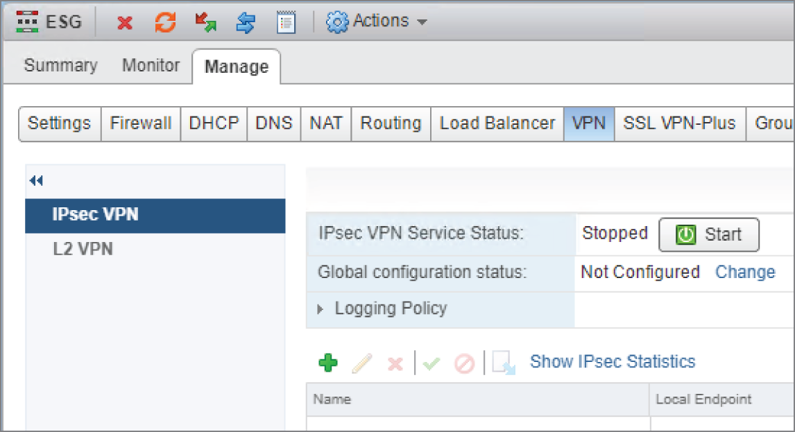
FIGURE 8.40 Deploying a site‐to‐site IPsec VPN
- Make sure that IPsec VPN is highlighted on the left, and then click the green + sign.
A new panel will appear (see Figure 8.41).
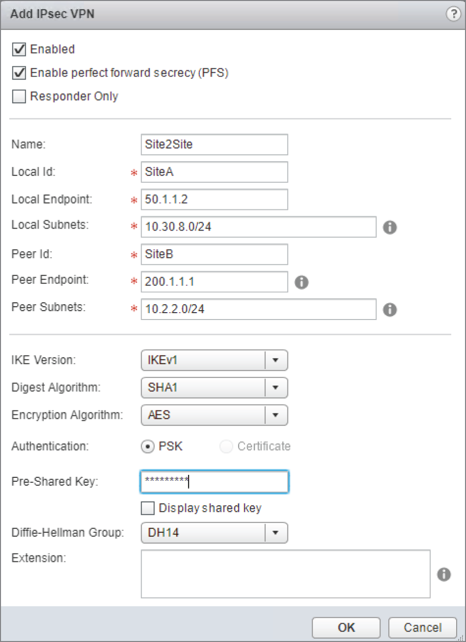
FIGURE 8.41 Configuring tunnel endpoints and peer subnets
In our example, the IP address on the ESG's uplink interface, which is used to connect to the perimeter router, is 50.1.1.2. This is the local endpoint of the tunnel. The other end of the tunnel is at SiteB. It's address, 200.1.1.1, is the peer endpoint of the tunnel.
Our goal is to give SiteB access to network 10.30.8.0/24. We see this listed in the Local Subnets field.
- To allow additional networks, simply add them to the same line but separate the addresses with commas.
SiteA requires access to network 10.2.2.0/24 on SiteB. We see that listed next to Peer Subnets.
In this example, beyond assigning the name Site2Site and entering the local IDs SiteA and SiteB, the rest are default options with the exception of the pre‐shared key, which needs to be entered on both sides and must match.
- After making your preferred configuration choices, click OK.
You must publish your configuration for it to be applied (see Figure 8.42).
- Click the Publish Changes button.
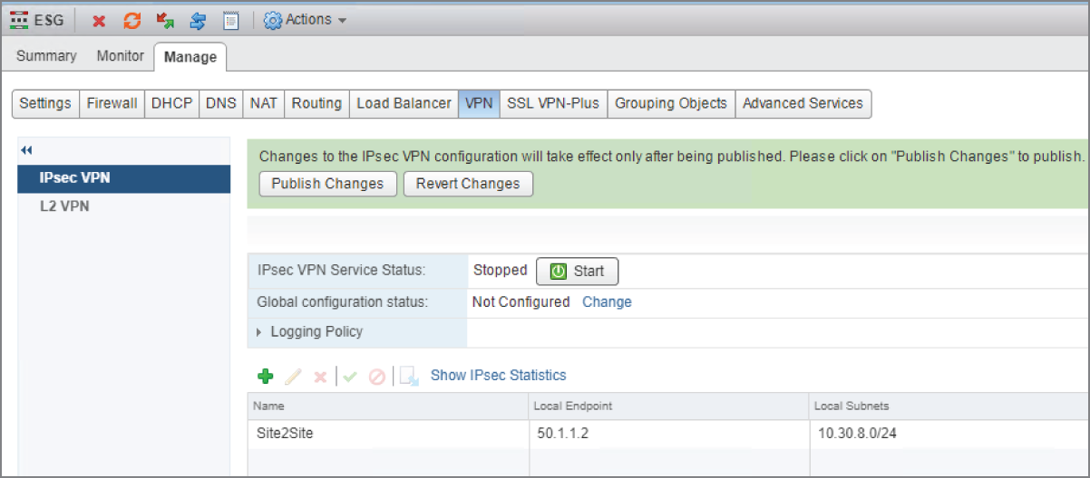
FIGURE 8.42 Publishing the changes
- Once publishing is complete, click the Start button (see Figure 8.43).
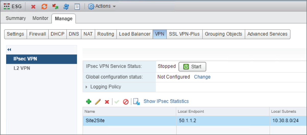
FIGURE 8.43 Starting the IPsec tunnel service
With the VPN similarly configured at the remote site, the tunnel will be established.
Round Up of Other Services
So far, we've looked at the primary services provided by an Edge Services Gateway: SNAT, DNAT, SSL VPNs, IPsec site‐to‐site VPNs, Route‐Based IPsec VPNs, Layer 2 VPNs (if you must), NAT, NAT‐T, one‐armed load balancer, inline load balancer, and let's not forget routing. With routing there was so much information, we had to give it its own chapter, especially since it was important to contrast the centralized routing provided by the ESG with the distributed routing provided by the DLR.
We still have another major ESG service to cover, that being the firewall. There is a lot of detail to cover there, so we're going to give it its own chapter as well. And just like we did with routing, we'll compare and contrast the centralized firewall service provided by the ESG to the Distributed Firewall (DFW).
But even putting that aside, there are still additional secondary services we have yet to discuss. These include the Dynamic Host Configuration Protocol (DHCP) service, DHCP Relay, and forwarding Domain Name System (DNS) requests to DNS servers.
DHCP Service
DHCP allows devices powering up to request an IP address from a pool of addresses configured on a DHCP server. The conversation between the device and the server goes like this (see Figure 8.44):
- Discover message from the client:
“Is there a DHCP server on this segment that can give me an IP address?”
- Offer message from the server:
“Yes, I'm a DHCP server. Here's my offer. Sign this lease and you'll get the IP 10.1.1.45, the subnet mask 255.255.255.0, the default gateway 10.1.1.1, the DNS server 8.8.8.8, and the domain name of Hydra1303.com. If you take it, you'll have the lease for 1 day.”
- Request message from the client:
“Perfect. I'll take it.”
- Acknowledgment message from the server:
“It's all yours. I'm going to jot down your MAC address so I remember who I gave this IP address to and put it in my binding table.”
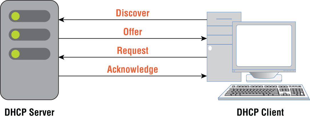
FIGURE 8.44 The exchange of DHCP messages
Since the IP address is pulled from a pool of addresses, it's possible to be assigned a different IP once the lease expires. If you want a VM to always be assigned the same IP address through DHCP, you can create a static reservation on the DHCP server. When the VM comes online and sends out the initial discover message, the DCHP server always hands it the same reserved address.
The NSX ESG can be configured to provide those DHCP services. Let's say that you have 20 Logical Switches. Each is a different subnet: 10.1.1.0/24, 10.1.2.0/24, 10.1.3.0/24, and so on. If you are using ESG to provide DHCP services, you do not need to deploy separate ESGs to support address pools for each subnet. Instead, a single ESG can support multiple pools of addresses. Physical DHCP servers can do the same.
Configuring the ESG as a DHCP Server
Using the standard vSphere Web Client, perform these steps:
- Go to Home ➢ Networking & Security ➢ NSX Edges.
- Double‐click the ESG you want to configure, and select the DHCP tab (see Figure 8.45).
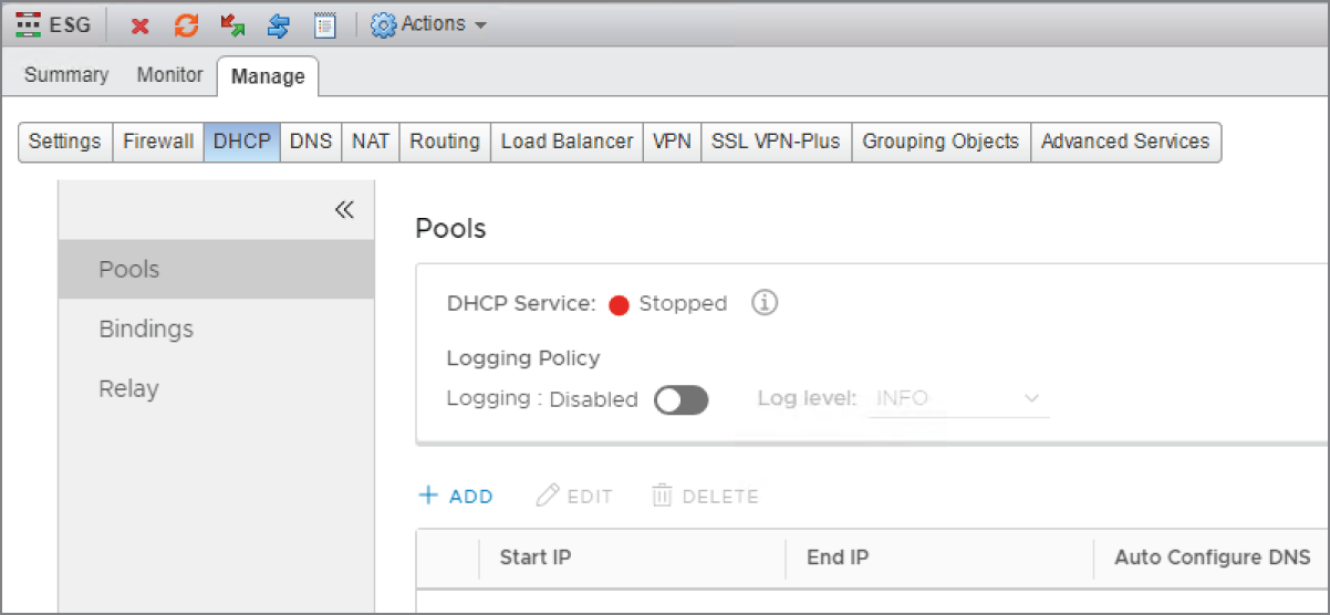
FIGURE 8.45 Adding a DCHP pool of addresses
- Select Pools from the left menu and click the + Add link.
A new panel appears (see Figure 8.46).
- Define the start and end range of IP addresses to hand out along with additional supporting IP information, such as the default gateway, subnet mask, DNS server addresses, domain name, and length of the lease.
- Click Add and then Publish to apply the configuration.
The DHCP service can then be enabled by clicking the Start button (see Figure 8.47).
- To create a DHCP reservation so that a VM gets the same address every time, select Bindings in the left menu and click the + Add link (see Figure 8.48).
- Select the Use MAC Binding option (see Figure 8.49).
Once this is active, anytime the ESG receives a DHCP request from this specific MAC address, it will be assigned the IP address 10.30.8.22 with the default gateway of 10.30.8.1.
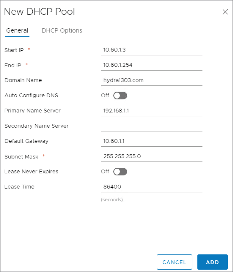
FIGURE 8.46 Defining the address range of the DHCP pool
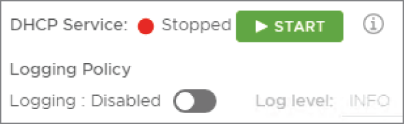
FIGURE 8.47 Starting the DHCP server service
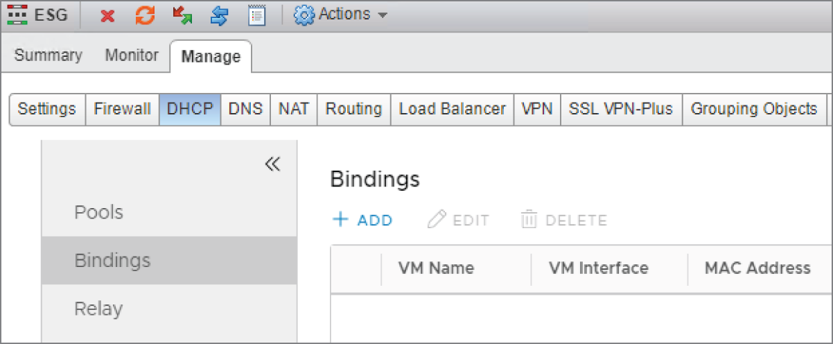
FIGURE 8.48 Configuring a DHCP reservation
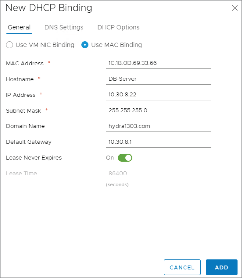
FIGURE 8.49 Ensuring a server is always allocated the same IP based on MAC address
- Be sure to set the Lease Never Expires option to On since we want the device to be assigned the same IP every time.
The field for the MAC address is a bit picky. A MAC address contains 12 hexadecimal characters and is sometimes expressed in pairs separated by colons or dashes (like 00:01:A6:5C:92:F1 or 00‐01‐A6‐5C‐92‐F1). Other times, it is shown in blocks of four numbers separated by dots (0001.A65C.92F1). You'll find that you can't complete this step unless the MAC address is entered as pairs of hex characters separated by colons.
- Go to the DNS Settings and DHCP Options tabs to add further supporting IP information.
- Click Add and Publish to apply the configuration.
DHCP Relay
DHCP was designed so that the initial discovery is done through a broadcast. Since the client doesn't have an IP address or default gateway at the start, we can't expect it find a DHCP server that is on a remote network simply by broadcasting. This is where DHCP relay comes in.
Let's say that we configured the ESG to provide DHCP services for every VXLAN. In the bottom‐left corner of Figure 8.50, we have VM‐A. It is configured as a DHCP client but has not yet been assigned an IP address.
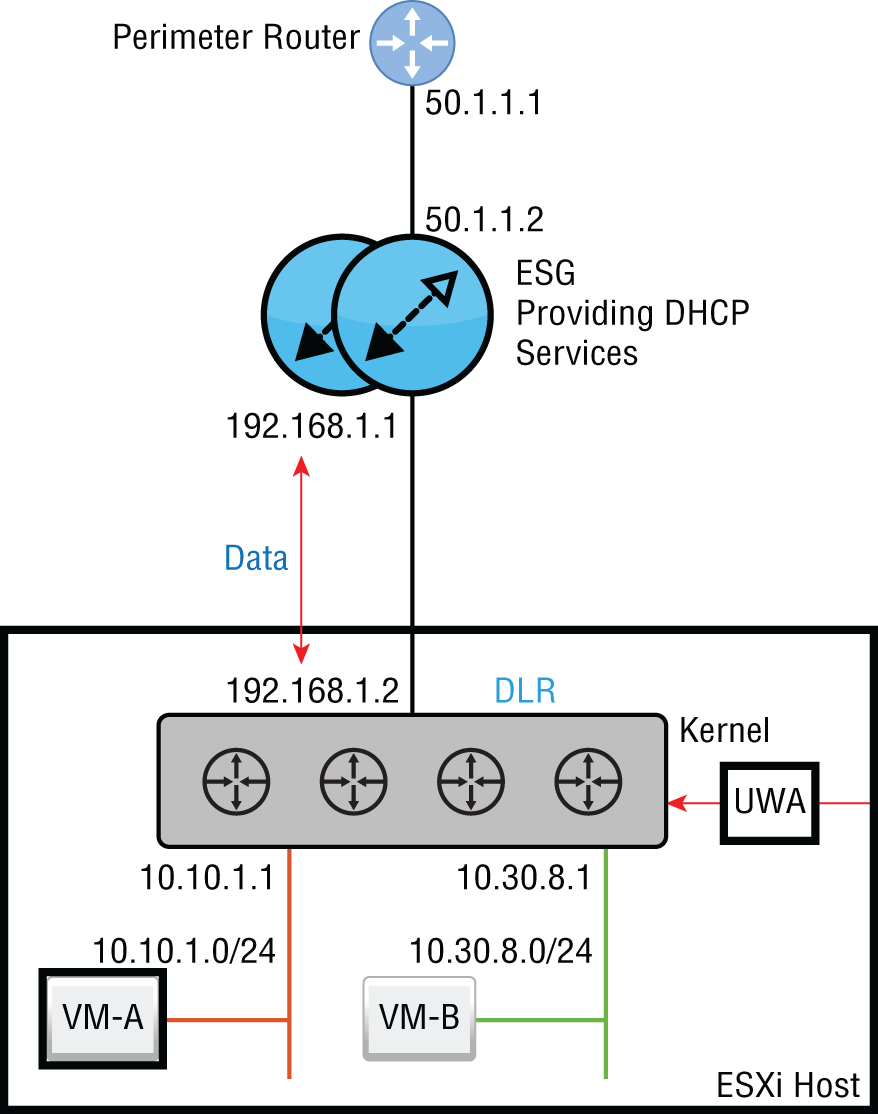
FIGURE 8.50 VM‐A powered off and without an assigned DHCP address
We power on VM‐A. It sends the broadcast Discover message: “Is there a DHCP server on this segment that can give me an IP address?”
The answer is no. The VM is on the 10.10.1.X subnet. The DLR, being a router, forms the boundary for that broadcast domain. Therefore, the broadcast is only heard on that local segment between VM‐A and the DLR. The broadcast can't reach the DHCP server.
The fix here is to configure the DLR interface 10.10.1.1 as a DHCP Relay Agent. Once configured, it listens on that interface for any DHCP Discover messages. When VM‐A is powered on and broadcasts that it's looking for a DHCP server, the DLR steps in: “I'm not a DHCP server, but I know where it lives. Let me help you out.” It then takes the broadcast Discover message, converts it to a unicast, and relays it to the ESG, the DHCP server.
The same back‐and‐forth DHCP conversation still takes place with Discover, Offer, Request, and Acknowledgment, but now with the DLR acting as the middleman. If the DHCP Relay Agent option didn't exist, we would need to have a separate DHCP server located on every segment. Managing all those servers would be a nightmare. Instead, we can centralize our DHCP pools and simply have the DHCP Relay Agents forward the requests they hear for IP addresses to the ESG.
It seems like the ESG might get confused. How does it know which pool to use when it gets a request for an IP address, especially since the devices requesting the IPs don't have addresses to begin with? The answer is simple. When the DLR changes the broadcast into a unicast, think what that packet (between DLR and ESG) would look like in terms of addressing.
The destination IP would be ESG 192.168.1.1, and in normal circumstances, the source address would be the outbound interface (the uplink) on the DLR, 192.168.1.2. Instead, the DLR changes its game and gets its source address from the interface where DHCP Relay is configured. In this case, that would be 10.10.1.1. This is the interface that listens for the DHCP Discover messages on the 10.10.1.0/24 segment.
Imagine you are the ESG. You've just received a DHCP message asking for an IP address from the agent 10.10.1.1. Based on the agent's address, you now know exactly which pool of addresses to pick from, the 10.10.1.X pool.
If the next address in the pool is 10.10.1.2, that's what the ESG sends to the DHCP Relay Agent as an available IP. The DHCP Relay Agent then forwards the message to VM‐A, and the conversation continues until the offer is requested and acknowledged.
Configuring the DLR for DHCP Relay
Using the standard vSphere Web Client, follow these steps:
- Go to Home ➢ Networking & Security ➢ NSX Edges.
- Double‐click the DLR you want to configure and select the DHCP Relay tab (see Figure 8.51).
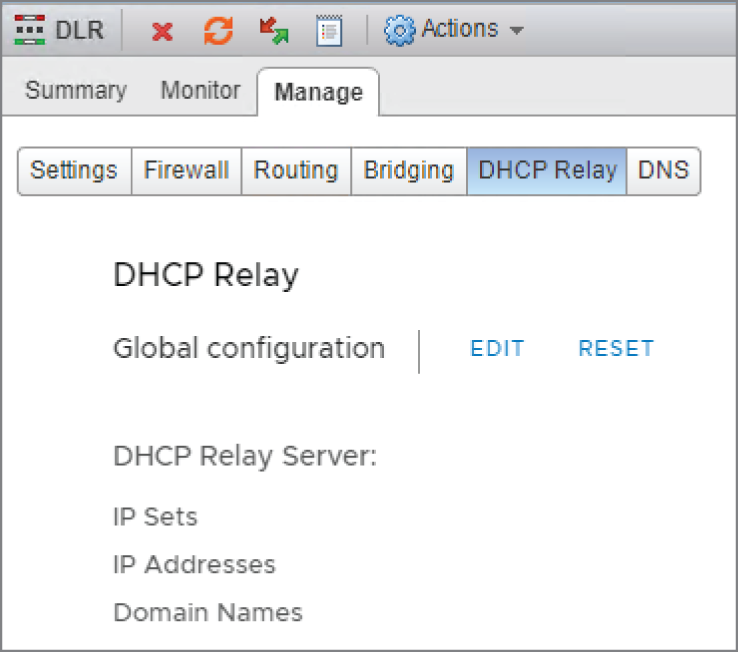
FIGURE 8.51 DHCP Relay to forward IP requests to a DHCP server on a different segment
- Click the Edit link next to Global Configuration.
There are several options to accomplish this, but the simplest is to add an IP address and domain name (see Figure 8.52). The IP address is the address of the DHCP server.
- Since the ESG is the DHCP server in this example, enter 192.168.1.1, and click Save and then Publish.
The lower half of the panel is for configuring the DHCP Relay Agent (see Figure 8.53).
- Click the + Add link.
A new panel appears: Add DHCP Relay Agent (see Figure 8.54).
- Select the vNIC on the DLR that the attached VMs use as their default gateway.
When you do, the Gateway IP Address should be populated automatically. In this example, the segment with the database servers is 10.30.8.0/24.

FIGURE 8.52 Pointing the DHCP Relay Agent to the DHCP server
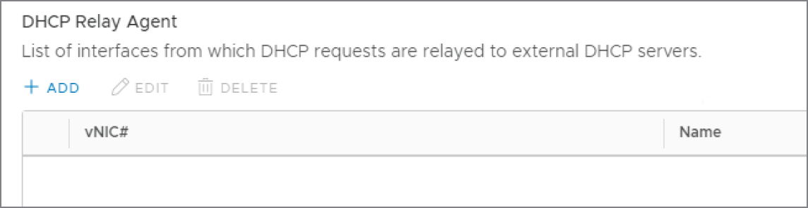
FIGURE 8.53 Adding the DHCP Relay Agent
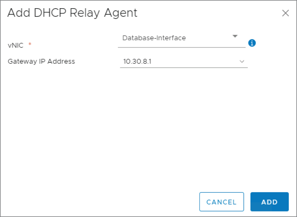
FIGURE 8.54 Selecting which interface will be the DHCP Relay Agent
Once configured, the interface listens for any DCHP messages heard on that connected segment.
- Click Add and Publish.
DNS Relay
The DHCP server bundles into the lease not only the IP address and subnet mask, but other supporting IP information as well. Typically, the IP address of the DNS server is included. The Domain Name Service allows clients to request the IP address associated with a Fully Qualified Domain Name (FQDN). Entering www.vmware.com in your browser triggers a DNS request to determine the IP address associated with the domain. The destination IP is required to route the traffic since there is no such thing as a name field in an IP packet. The source and destination must be IP addresses.
An ESG can't be configured as a DNS server. However, similar to the way a DHCP Relay Agent forwards messages to a DHCP server, an ESG can receive a DNS request and relay it to a DNS server.
Let's say that you wanted all name resolution to be handled by Google's DNS server, 8.8.8.8. It seems like configuring the ESG to relay a DNS request to 8.8.8.8 is unnecessary. A simpler solution would be to announce in the lease that the DNS server is 8.8.8.8. We don't have to worry about a broadcast not getting through the DLR like we did with the DHCP Relay Agent example because DNS messages aren't sent as broadcasts. They are unicast messages. The DLR will have no problem routing them appropriately. This option may be simpler, but you'll still want to configure DNS relay instead.
The real reason for leveraging DNS Relay in this scenario is that when the request comes in, it caches the answer received from the actual DNS server.
In the diagram in Figure 8.55, VM‐B needs to access a file on ftp.hydra1303.com, but in order to address the packet, it needs to know the IP address, so it sends the request to what it has listed as its DNS server: 192.168.1.1, the ESG.
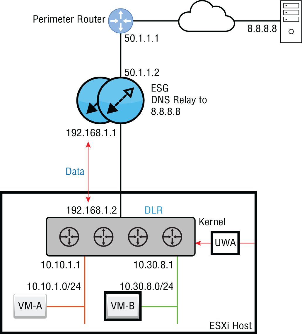
FIGURE 8.55 Relaying DNS requests to a DNS server on a different segment
The DNS request is received by the ESG, which isn't a DNS server, but it has been configured to relay any DNS requests to 8.8.8.8. The Google DNS server receives the request and answers the ESG, saying that the IP mapped to that domain name is 45.60.11.183.
At this point, the ESG caches the mapping ftp.hydra1303.com = 45.60.11.183 and sends the answer to VM‐B. From this point on, if anyone from our organization needs to reach ftp.hydra1303.com, the request will be answered immediately by the ESG without having to leave the NSX environment since the requested information is stored in cache.
Configuring DNS Relay on the ESG
Using the standard vSphere Web Client, perform the following steps:
- Go to Home ➢ Networking & Security ➢ NSX Edges.
- Double‐click the ESG you want to configure, and select the DNS tab (see Figure 8.56).

FIGURE 8.56 Configuring DNS forwarding on the ESG
- Click the Change link.
A new panel appears: Change DNS Configuration (see Figure 8.57).
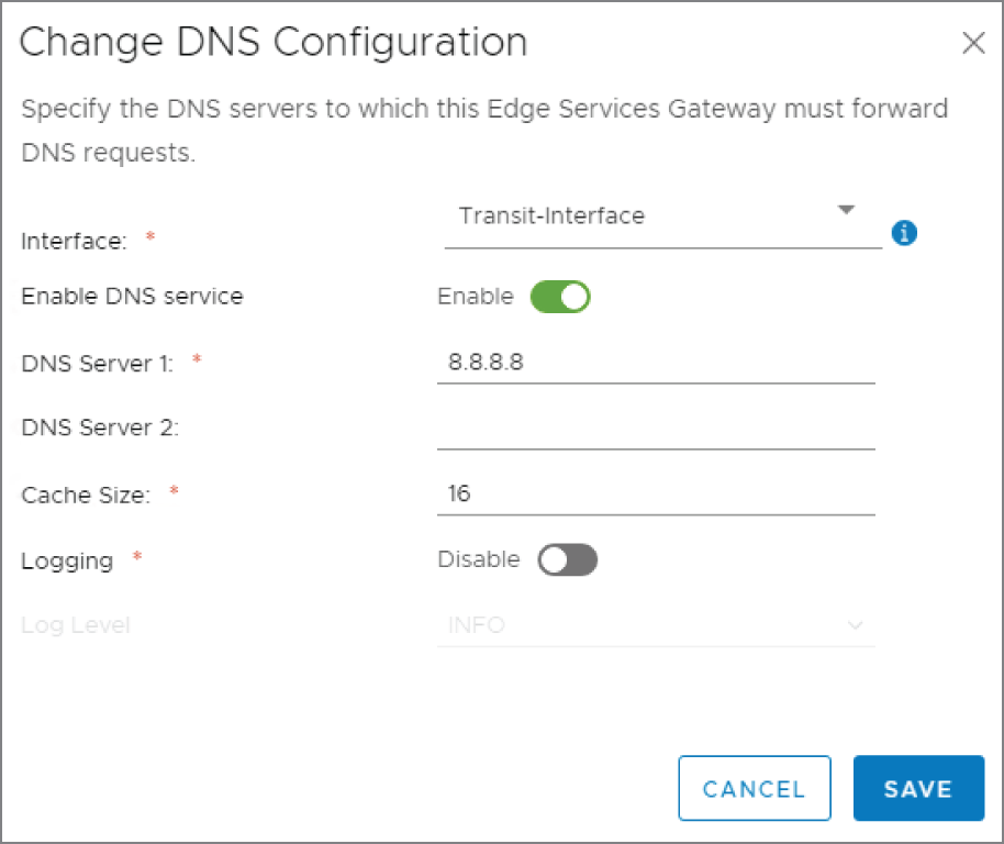
FIGURE 8.57 Directing the ESG to forward DNS requests to 8.8.8.8
- Use the drop‐down to select the interface that should be listening for DNS requests.
- Click the slider to enable the DNS forwarding service. Then add the address of the DNS server.
The DNS server doesn't have to be external to your NSX environment. You can also point to a local DNS server using the same steps.
- Click Save.
The Bottom Line
- Matching VPN Solution to Use Case The NSX Edge Services Gateway supports several types of VPNs to support different use cases. When choosing a VPN solution, factors to consider include temporary vs. permanent and mobile vs. fixed locations.
- Master It Your organization has contractors based in different countries who travel to customer sites. To access resources within the corporate data center in New York, which type of VPN would you configure for these workers?
- Site‐to‐site VPN
- Layer 2 VPN
- Layer 3 VPN
- SSL VPN
- Master It Your organization has contractors based in different countries who travel to customer sites. To access resources within the corporate data center in New York, which type of VPN would you configure for these workers?
- Benefits in Balancing Availability and scalability are always a concern in any network. Load balancing provides both. For example, if you are load balancing traffic across four servers, availability is not affected if one server needs to be taken down for maintenance. The other three continue working, and the service remains available. Or say you are load balancing across four web servers. You can scale up and add more servers to improve performance when needed or scale down by removing servers when overall utilization decreases.
- Master It Which of the following is not a valid load balancer configuration choice when specifying how the ESG will split the incoming traffic to connected servers?
- Weighted round‐robin
- IP hash
- Least used connection
- Most used connection
- Master It Which of the following is not a valid load balancer configuration choice when specifying how the ESG will split the incoming traffic to connected servers?
- Choosing the Right Interface to Relay An Amazon delivery driver places a package on your porch and rings the doorbell. The bell rings throughout the house but no one is home to hear it. This is analogous to a DHCP Discover message. It's a broadcast intended for the local segment, which is fine if you have a DHCP server on that segment (or for the analogy, that someone is home). DHCP Relay is like having a smart doorbell connected to the cloud. When the doorbell button is pressed, it sends live video to your phone allowing you to communicate with the delivery driver. Similarly, DHCP Relay forwards the message to the ESG, which responds with an offer.
- Master It In Figure 8.50, the admin configured a DHCP Relay Agent so that VM‐B could successfully receive an IP address from the ESG. On which interface did the admin configure DHCP Relay to get this to work?
- 192.168.1.1
- 192.168.1.2
- 10.30.8.1
- 10.10.1.1
- Master It In Figure 8.50, the admin configured a DHCP Relay Agent so that VM‐B could successfully receive an IP address from the ESG. On which interface did the admin configure DHCP Relay to get this to work?