
Chapter 2
NSX Architecture and Requirements
In this chapter, we will review the architecture of NSX to understand better how network virtualization is accomplished and compare this to how it has been handled traditionally. It is important to understand the architectural components, their functions, and how they interoperate with each other before diving into features and options we will cover later throughout the book.
NSX depends on VMware vCenter and vSphere Distributed Switches to work across multiple ESXi hosts. These provide the foundation necessary for NSX to build upon. By integrating with vCenter, NSX doesn't have to be managed separately. We will see that management is further simplified using predefined administration roles with Role-Based Access Control.
NSX allows virtual networks to be created on top of an existing physical network. We will discuss how this is accomplished and find that implementing it requires little to no changes to the physical network. This means that getting the benefits of NSX doesn't mean having to alter your existing infrastructure or invest in new hardware. NSX leverages the existing network by creating a virtual overlay network.
NSX Network Virtualization
VMware NSX provides network virtualization. Like a VMware hypervisor, which abstracts the underlying physical compute and memory, network virtualization is essentially a hypervisor abstracting the physical network. The physical network is still connecting the physical devices, but the L2 through L7 network services are reproduced in software (see Figure 2.1), including all the components and functions you normally associate with networking: routing, switching, firewalls, load balancing, NAT, DHCP, QoS, and access lists.

FIGURE 2.1 Network virtualization decoupling network functions from the physical hardware
Having all these network functions wholly contained in software provides flexibility with these services that would be impossible on dedicated hardware devices. Provisioning can often be as simple as a few clicks.
Planes of Operation
With traditional networking, there are three planes of operation (management, control, and data) all contained within a single device (see Figure 2.2).

FIGURE 2.2 Traditional three planes of operation found in each networking device
For example, a router has a management plane, which provides a configuration point to enter commands via a Command Line Interface (CLI) or to select options using a Graphical User Interface (GUI). A routing protocol like Open Shortest Path First (OSPF) would be configured here. The routing protocol allows that router to exchange routing information with other routers. As an analogy, you could think of the management plane as a company boardroom where the goals of the organization are defined.
Continuing with the analogy, the control plane would be like a department supervisor at the company (see Figure 2.3). Supervisors are given their goals from management, but it's up to the supervisors to determine how to best get the job accomplished. The control plane is where learning occurs and decisions are made. In the case of the router, it has collected information from other routers and determined the best interface to exit to reach each destination and put that into a routing table.
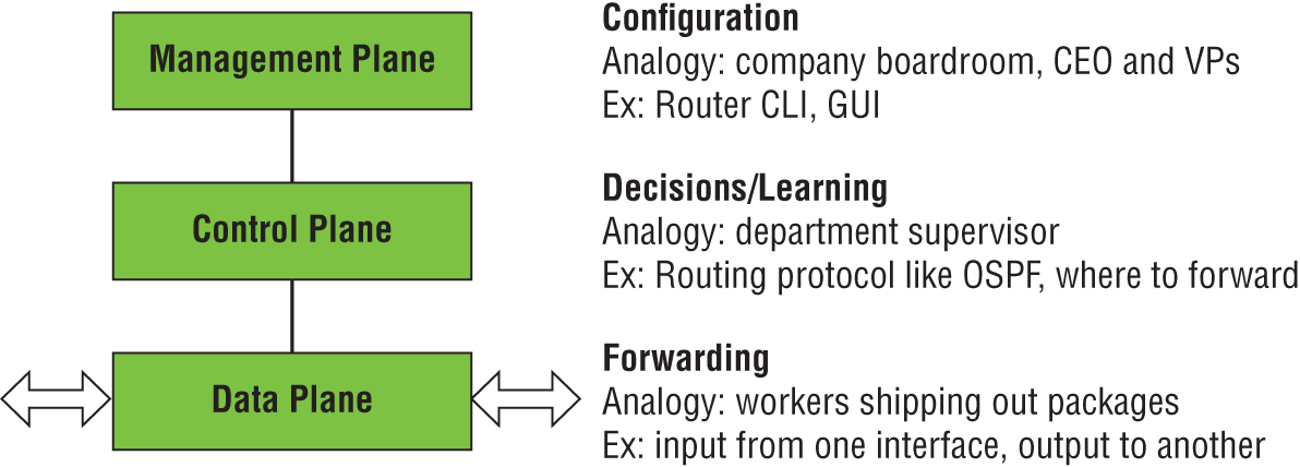
FIGURE 2.3 Network planes of operation compared with company job roles
But the supervisors don't do the heavy lifting. They instruct the workers to complete the tasks. This is what happens in the data plane, which is concerned with forwarding the traffic out of the interface that was learned and decided by the control plane.
In traditional networking, this process is repeated for every device (see Figure 2.4). Every router and every switch makes its own decisions on where to forward traffic based on the intelligence it has gathered in the control plane.

FIGURE 2.4 Each networking device in traditional networking making decisions independently
NSX Manager Role and Function
With NSX, the management, control, and data planes are separate instead of being housed together in each virtual networking device. Management is centralized from a single point, the VMware NSX Manager (see Figure 2.5). It is a virtual appliance used to provision, configure, and monitor NSX virtual network devices such as logical routers, switches, firewalls, and load balancers. Because it's centralized, it obviates the need to log in to each virtual component separately.
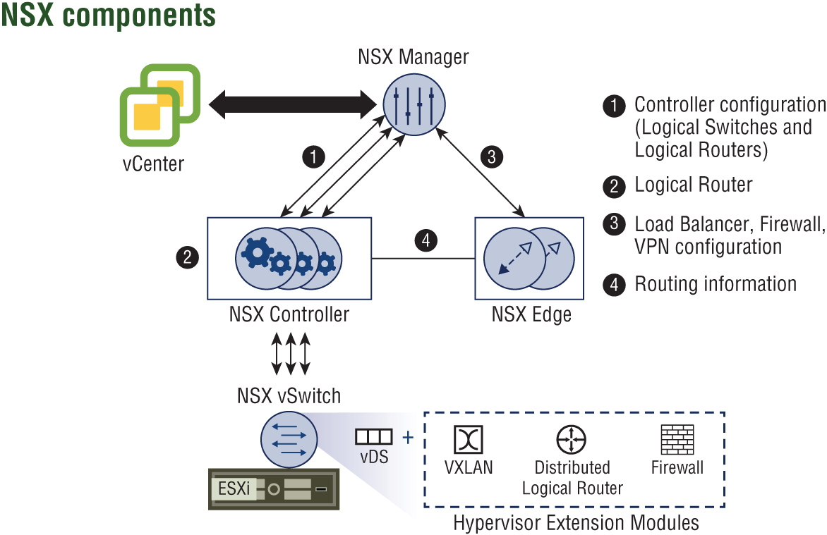
FIGURE 2.5 NSX architecture
Accessing the NSX Manager can be accomplished using the vSphere Web Client to make manual changes, or the same tasks can be executed programmatically using REST APIs (see Figure 2.6). REST APIs allow objects that can be accessed through a URL to be created or modified. Consider the time and effort required to move or re-create a physical network. In comparison, a single administrator could automate the re-creation of an entire network of virtual routers, switches, firewalls, and the like at another site with minimal effort by scripting the tasks with REST APIs. However, it's not necessary to be a programmer to accomplish this.

FIGURE 2.6 Accessing NSX Manager using the same web client used for vSphere
VMware offers a cloud management platform, vRealize Automation, which uses REST APIs under the hood to automate the deployment and control of NSX components (see Figure 2.7). As the name of the platform suggests, it can also centrally manage cloud services, both public and private, across vendors.
FIGURE 2.7 Deploying and controlling NSX components through automation
NSX Manager is a virtual machine installed on an ESXi host, which is packaged as an Open Virtual Appliance (OVA) file. The benefit of installing it as an OVA is that it will be assigned a unique identifier known as a UUID. Having a unique identifier is essential in a cross-vCenter environment, which allows multiple sites to each have a separate NSX Manager.
In these instances, there is a primary NSX Manager and one or more secondary NSX Managers (see Figure 2.8). The primary NSX Manager can create universal firewall rules, universal logical routers, universal logical switches, and the like whose services are available to all sites.
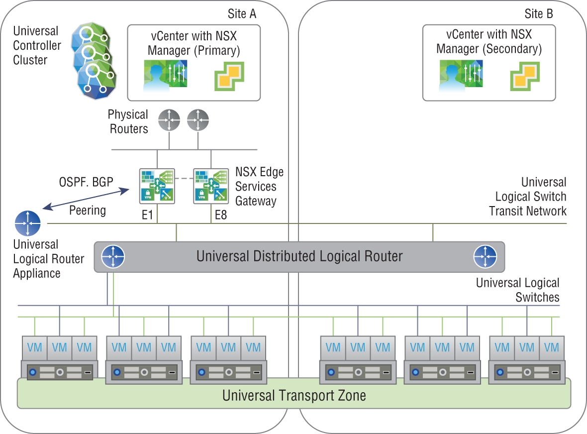
FIGURE 2.8 Primary NSX Manager at Site A managing secondary NSX Manager at Site B
ESXi Hosts
VMware recommends that you deploy NSX Manager on a management cluster of at least three ESXi hosts that is separate from the compute cluster and configured with VMware High Availability (HA) and VMware Distributed Resource Scheduler (DRS). HA is achieved by deploying members of the cluster in an active/standby configuration. If the active component fails, the standby takes over and continues to provide the services. DRS can be configured to use an anti-affinity rule that ensures that the active and standby components are always installed on different hosts to increase availability (see Figure 2.9). That way, even if an entire host were to fail, NSX Manager would still be available with a standby becoming active. NSX Manager doesn't have HA and DRS built in; instead, it relies on ESXi's HA and DRS features.

FIGURE 2.9 Compute clusters separated from management clusters, increasing availability
The management and compute clusters should also not share the same IP address space. The compute clusters will be where your software-defined networks are deployed. Separating management and compute increases availability for both; for example, even in the event of entire management plane failure, production traffic would continue to be forwarded. However, since configuration is accomplished by way of the management plane, no changes could made until the connection to NSX Manager is restored.
vCenter Server
Whereas VMware NSX Manager provides a centralized point for managing an NSX environment, VMware vCenter Server provides a centralized point for managing vSphere environments. vCenter allows an administrator to perform tasks such as deploying VMs and creating logical switch port groups. Rather than requiring an NSX administrator to separately log in to vCenter Server to perform these operations, they can be accomplished directly from NSX Manager. NSX Manager does this by registering and communicating with vCenter Server using the VMware vSphere API. There's a one-to-one relationship between NSX Manager and vCenter Server, with one NSX Manager only connected to one vCenter Server (see Figure 2.10). This holds true even in a Cross-vCenter environment over multiple sites. For every instance of NSX Manager, there is one vCenter Server. Once the NSX Manager registration with a vCenter Server is completed, the registration cannot be changed to communicate with a different vCenter Server. Instead, a new NSX Manager would have to be deployed to register with a new vCenter Server and the former NSX Manager deleted.
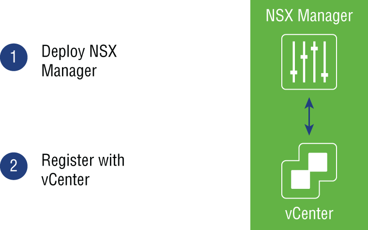
FIGURE 2.10 NSX Manager can only be registered to one vCenter Server.
vSphere Distributed Switch
Prior to vSphere Distributed Switches (VDSs), a vSphere administrator would typically configure individual virtual switches on a per-ESXi host basis (see Figure 2.11). The vSphere administrator would then have to coordinate with network infrastructure administrators so that the configuration of VLANs was consistent. After deployment, both teams would need to be involved in troubleshooting and monitoring the data center.
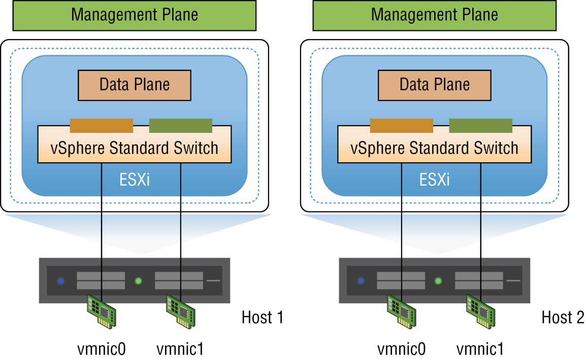
FIGURE 2.11 Individual vSphere Standard Switches
VMware vSphere Enterprise Plus includes a vSphere Distributed Switch (VDS), which works across multiple ESXi hosts (see Figure 2.12). The VDS is also shipped with a vSAN license. The VDS allows the management of VM networking and the configuration settings like virtual switch port configuration and port group naming to be accomplished centrally. It treats the vSphere network as a collective resource by setting up switching that can span the data center. Communication from a VM on one host to a VM on another host doesn't require coordination with the infrastructure team. Configuration is simplified and can be done centrally across multiple ESXi hosts. This aggregation provides the foundation for enabling Software-Defined Network configurations, which is where NSX comes in.
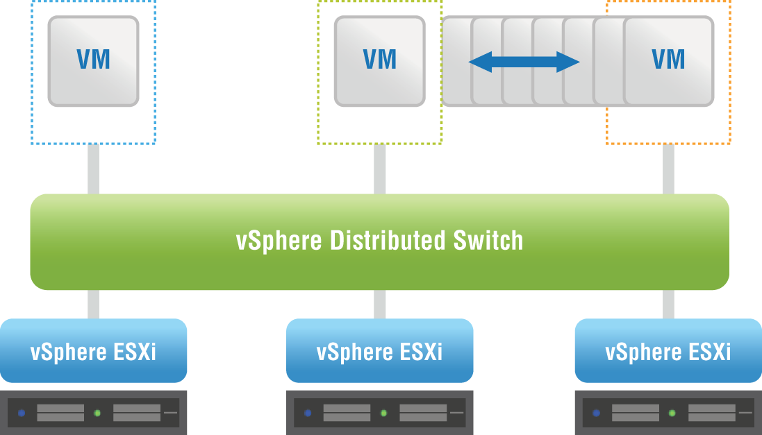
FIGURE 2.12 A vSphere Distributed Switch spanning several ESXi hosts
The NSX data plane is provided by the VMware NSX Virtual Switch, which is based on the vSphere Distributed Switch, but with additional components that allow virtual networking services to be enabled such as logical switching (VXLAN), logical routing, and logical firewall (see Figure 2.13). The complexities of the physical network are abstracted by the NSX Virtual Switch, which provides access-level switching in the hypervisor. This makes the virtual network simpler to design when it comes to subnets. VMs located on completely different hosts can be part of the same subnet, even if there is an L3 barrier between the hosts on the physical network.

FIGURE 2.13 The data plane for the overlay network, provided by the NSX Virtual Switch
For example, if several ESXi hosts were connected by an underlying physical network with a router between each pair of hosts, in the physical network, these routers would define the boundaries of L2 domains. A subnet could only span a single host. However, with the physical network treated as if it were one giant switch, then the L2 domain, an IP subnet, could potentially stretch from end to end of the data center. A VM on ESXi host 1 could communicate with a VM on ESXi host 8 with simplified addressing (see Figure 2.14). They can be assigned to the same subnet. And with the abstraction of the physical hardware, there's no need to coordinate with the infrastructure team, requesting that they create matching VLANs. End-to-end communication within the NSX environment can be implemented solely by the NSX administrator.

FIGURE 2.14 VMs on separate hosts but members of the same 10.1.1.0 subnet
NSX VIBs
The kernel modules that are added to the NSX Virtual Switch to enable virtual networking services, the necessary configuration files, installation scripts, and agents for internal communications are packaged into vSphere Installation Bundles, or VIBs (see Figure 2.15). These compressed packages are the building blocks that allow you to customize the ESXi hosts and create the NSX virtual environment. VMware Certified VIBs are created and tested by VMware, so you're not having to manually collect individual files and worry about compatibility. Everything within the bundles is designed to work together, and for security, the VIBs are digitally signed.
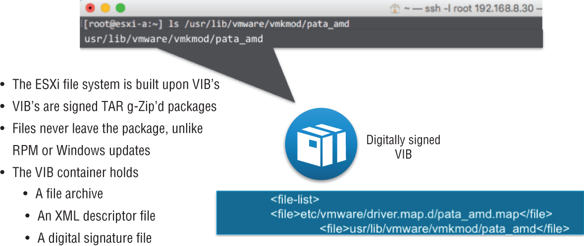
FIGURE 2.15 vSphere Installation Bundles used to create the NSX virtual environment
The types of services the VIBs provide include distributed routing, VXLAN bridging (a form of tunneling through the physical network to logically connect ESXi hosts), and logical firewalls.
Competitive Advantage: IOChain
Within an ESXi network, an IOChain provides the ability to insert different quality control functions into the data path.
Examples include:
- The ability to do ingress and egress bi-directional traffic shaping to mitigate congestion
- Link Aggregation Control Protocol (LACP) and Load Balanced Teaming (LBT) to load balance traffic
- Network I/O Control (NIOC) to provide bandwidth guarantees for VMs as well as for system traffic
- Support for VLAN tagging and filtering
- Monitoring options for traffic flow control
IOChain Security Features
In addition to quality control functions, security services are also implemented as IOChains within the kernel. These are automatically applied when a VM is connected to a logical switch. A Distributed Virtual Filter (DVFilter) is an access list that examines traffic entering and leaving the virtual NIC or virtual Network Interface Card of the virtual machine.
A switch security (swsec) module examines packets to learn the IP and MAC address of the VM. Additionally, it listens for Address Resolution Protocol broadcasts that come from the VM. In a physical network, those ARP broadcasts are picked up from the wire and sent up the stack of every device within the same subnet. This means that even if a device is not the intended receiver of the message, it still consumes CPU. With NSX, these ARP broadcasts are handled much more intelligently. Rather than allowing the broadcast to be propagated and impacting the performance of the other devices, the switch security module redirects the message to the NSX Controller only. The Controller learns all the IP/MAC mappings and can return the requested information to the VM without needing to blast the request out as a broadcast to every other device within the broadcast domain. This feature is called ARP suppression. It improves the performance of every device throughout the data center since ARP normally generates a lot of broadcast traffic on the network. Another feature handled by the switch security module is NSX IP Spoofguard. As the name suggests, it prevents the spoofing of IP addresses.
This is also where the NSX Distributed Firewall (DFW) is implemented. Firewall rules are stored and carried out here as packets enter or leave the VM.
Within the IOChain, there are also slots available to add third-party services, which greatly enhances and extends the abilities and options available for the NSX environment. For example, another vendor may have a firewall or load balancer with specialized features that are beyond what VMware provides. NSX makes it possible to redirect traffic to those third-party appliances (see Figure 2.16).
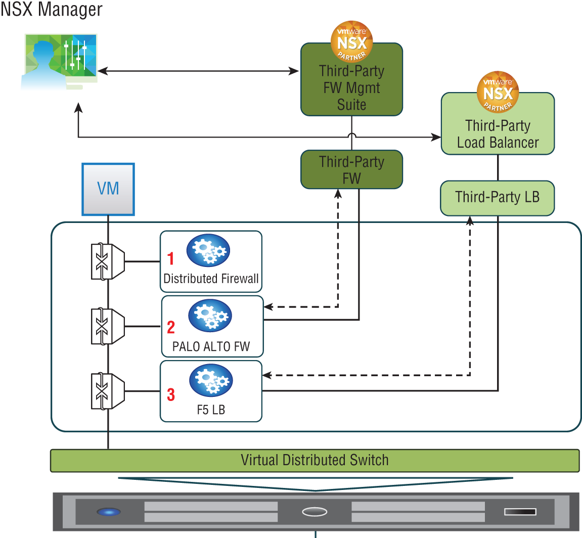
FIGURE 2.16 IOChain with customizable slots for adding third-Party functions
NSX Controllers
As a quick review of the NSX planes of operation, the management plane (for configuration) is created and handled by the NSX Manager. The data plane (for forwarding traffic) is implemented in the NSX Virtual Switch. But what about the control plane (for learning/decision making)? The control plane is found in the aptly named NSX Controller cluster. The Controller cluster is responsible for managing the switching and routing kernel modules (see Figure 2.17). It learns and maintains information related to every ESXi host, the Distributed Logical Routers, and the logical switches, which are also referred to as VXLANs. Based on the information it receives, it's able to make the decisions for routing, for switching, and the like. But more importantly, it's able to then distribute this information to every ESXi host and ultimately make its way into their kernels. From its stored information, it's able to return the mappings of IP to MAC addresses requested as a result of ARP suppression, for example. This optimizes the performance of the data center, with all ARP traffic being handled in software instead of being blasted out as a broadcast in hardware.
Not only do the controllers collect this information, but more importantly, they propagate the information to the other ESXi hosts, which ultimately makes its way into the respective kernels of the hosts. This distribution of forwarding, security, and quality control is what allows actions on traffic to be taken directly without having to exit the host, get the required information, return to the host, and then finally forward packets.
FIGURE 2.17 The NSX controller Cluster controls routing and switching for each host.
NSX Controller Clustering
The NSX Controller is in the form of a VM. When deploying NSX Controllers in production, it's recommended that there should be three in a cluster, but that each VM should reside on a different ESXi host (see Figure 2.18). One reason for this is fault tolerance. If an entire host were to fail, the remaining two controllers would continue to function and would take on the workloads of the failed host. Another reason is scalability. Part of the NSX Architecture design for scalability is to ensure that all NSX Controllers are active at any given time, so that they can share the workload.
NSX Controller Roles
The mechanism for doing this is called slicing or sharding. The three controllers will have elections to decide which will be the master NSX Controller instance for a particular role. Controller 1 might be the master for the logical switching (VXLAN) role, and Controller 2 might be the master for the logical routing role. The same is done for other NSX services.
The masters for the roles are responsible for dividing the workload into slices and then assigning which controller will handle which slices (see Figure 2.19).
FIGURE 2.18 NSX Controllers deployed three to a cluster, each on a different host
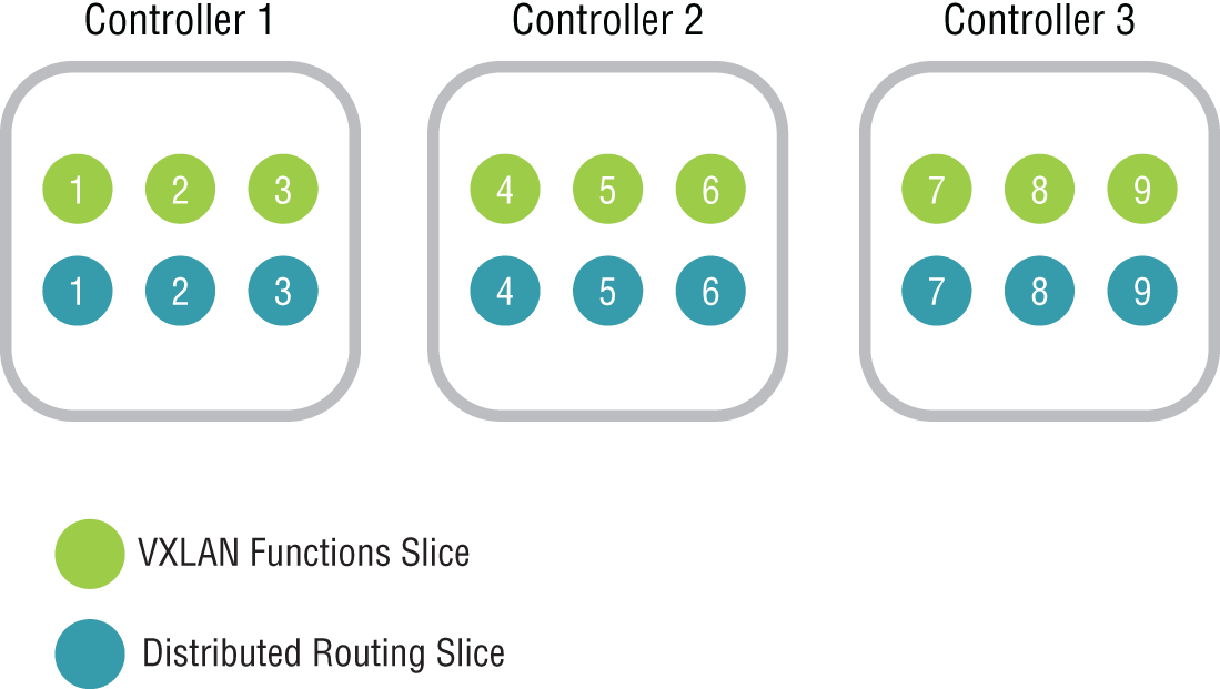
FIGURE 2.19 Dividing the workload into slices/shards, assigned across the three controllers
Let's say that Controller A is the master controller for logical routing, and it has divided the workload into six slices. It would assign slice 1 to itself, slice 2 to Controller B, and slice 3 to Controller C. Slices 4, 5, and 6 would be handed out in the same way, to Controllers A, B, and C, respectively. When a request comes in on logical router shard 3, for example, it is directed to Controller C (see Figure 2.20).
Each master is also responsible for keeping track of the other controllers to determine if a controller has failed. If this happens, the master of each role would redistribute those affected shards to the remaining controllers. The election of the master for each role is done by a majority vote. It's for this reason that we start with three controllers in a cluster. Being an odd number, it's enough to break a tie, so always deploy an odd number of controller instances for this reason.
Reslicing/resharding will occur any time there is a change in the number of controllers. This means the slices will be reallocated when:
- An NSX Controller is created
- An NSX Controller is deleted
- An NSX Controller fails
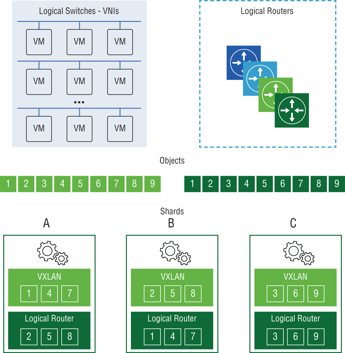
FIGURE 2.20 Job of two roles, VXLAN Logical Switches and Logical Router, divided into shards and allocated across Controllers A, B, and C
NSX Edge
The NSX Edge can be installed as an Edge Services Gateway (ESG) or as a Distributed Logical Router (DLR). As an ESG, routing is centralized, and it is typically used for routing traffic in and out of your virtualized network. This is referred to as North-South traffic (see Figure 2.21). For example, traffic between a VM and the Internet would be considered North-South. An ESG shares similarities with a traditional router or firewall. Each ESG can have up to 10 vNIC interfaces.

FIGURE 2.21 NSX Edge routes traffic between your virtual and physical networks.
With a DLR, routing is distributed and is primarily used for forwarding East-West traffic. This is traffic from VM to VM within your data center. Because the routes are distributed into the kernels of each ESXi host, there's no need to cross the network to find out the route to reach the other VM. The host already has the answer, greatly improving performance. When it comes to logical interfaces (LIFs) on a DLR, there can be up to 999 on each, plus one for management.
The NSX Edge Services Gateway (see Figure 2.22) provides several logical networking services that can be provisioned on demand, including:
- Firewall
- Network Address Translation (NAT)
- Routing
- L2 and L3 VPNs
- DHCP and DNS relay
- Load Balancing
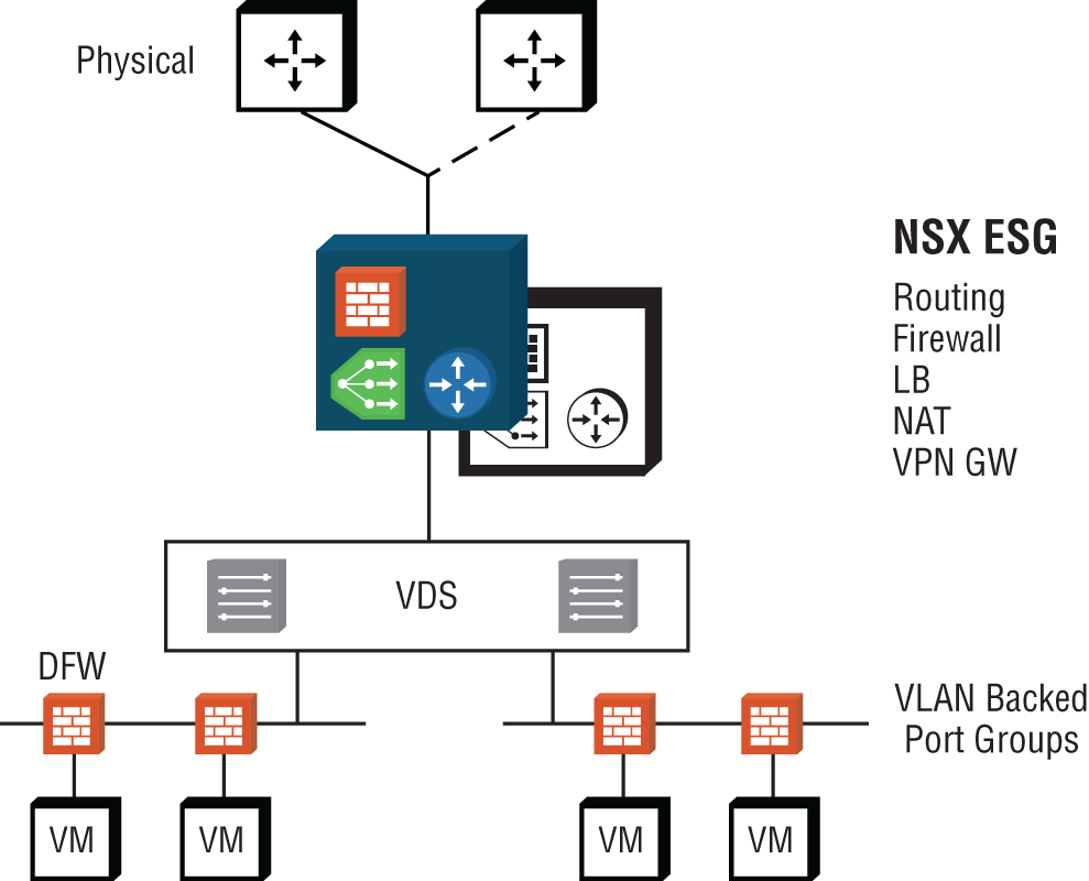
FIGURE 2.22 NSX Edge services
The firewall can work alongside the Distributed Firewall (DFW), with the ESG firewall focusing on North-South traffic in and out of your virtualized network and the DFW dealing with East-West traffic within your data center.
For address translation, the NSX Edge supports both source NAT and destination NAT.
For routers to exchange routes dynamically, a routing protocol is necessary. The NSX Edge supports iBGP, eBGP, and OSPF. Static routing is also available to manually configure routes.
Site-to-site IPSec Layer 2 and Layer 3 VPN services allow data centers that are spread out geographically to extend their domains. Remote access VPNs using SSL are also supported.
DHCP and DNS Relay services intercept requests from within your virtualized network and forward them to a DHCP or DNS server within the physical network.
The NSX Edge provides a Load Balancing service to dynamically spread a workload over a server farm cluster.
The NSX Edge is a VM. You can have two Edge VMs: one in active mode, the other in standby. Another design choice for the NSX Edge is Equal Cost Multi-Path (ECMP) mode. This allows up to eight Edge VMs acting as DLRs. This provides higher bandwidth and faster convergence; however, the only service available with this option is routing.
ESG Sizing
ESGs can be deployed in four different sizes: Compact, Large, Quad-Large, and X-Large. The larger the size, the more vCPUs and RAM required, as shown in Table 2.1.
TABLE 2.1 Sizes of ESGs
| Size | vCPU | RAM | Use Case |
| X-Large | 6 vCPUs | 8 GB RAM | High performance, combining multiple services, firewall, load balancing, and routing |
| Quad Large | 4 vCPUs | 1 GB RAM | High-performance single service such as ECMP DLRs or as a high-performance firewall |
| Large | 2 vCPUs | 1 GB RAM | Medium performance; a single service or for a small data center |
| Compact | 1 vCPU | 512 MB RAM | Low-resource services such as a DHCP/DNS relay or lab/test environment |
When a pair of ESGs are deployed in an active/standby configuration, a heartbeat signal is exchanged between them. By default, if the heartbeat is no longer heard by the standby ESG for 15 seconds (known as the dead time), the standby takes over. It's possible to upgrade the size of the ESG in a live production network, but doing so will incur downtime. The outage of the ESG service can be reduced down to 6 seconds, the minimum setting for the dead time.
NSX Role-Based Access Control
Role-Based Access Control (RBAC) is assigning access to resources on the basis of someone's role in the organization. Groups are created for each role, and permissions are assigned to each group. By making a user a member of a group, they are granted those assigned permissions.
NSX Manager has several pre-built RBAC roles, including Auditor, NSX Administrator, Security Administrator, and Enterprise Administrator (see Figure 2.23).
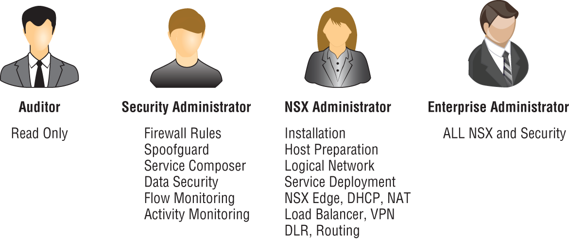
FIGURE 2.23 RBAC pre-built roles for assigning access to NSX
Auditor
- Can't make configuration changes
- Can only view the system
NSX Administrator
- Can perform all tasks related to deploying and administering an NSX Manager instance
- Examples: can install virtual appliances, can configure port groups
Security Administrator
- Can configure security policies and view the reporting and auditing information in the system
- Examples: define firewall rules, configure NAT, configure load balancing
Enterprise Administrator
- Has all of the rights of the NSX Administrator
- Has all of the rights of the Security Administrator
Security Engineer
- Can't prepare hosts
- Can't manage user accounts
- Can perform all security tasks
- Can have read access to some networking features
- Examples: define firewall rules, configure policies
Network Engineer
- Can't access security features
- Can perform all networking tasks
- Examples: routing, switching, DHCP
Security and Role Administrator
- Has all of the rights of a Security Engineer
- Can also manage user accounts
A user can only have one role. Assigning a user to a role will grant them access to use the Networking & Security plug-in found in the vSphere Web Client and to access the NSX Manager. It's recommended with RBAC to only grant permissions to groups, not individual users. This makes permission management simpler and in some cases is required for compliance.
Overlay and Underlay Networks
NSX allows virtual networks to be created on top of an existing physical network. The virtual network is referred to as the overlay, and the physical network is the underlay. Most organizations looking to upgrade their networks prefer the ability to leverage their current network (a brownfield deployment) and don't have the luxury of being able to simply create a brand-new network from scratch (a greenfield deployment). This is where NSX really shines. For the most part, adding a virtual NSX overlay requires little to no changes to the physical underlay. This means avoiding that fork-lift upgrade while still getting all the benefits that NSX brings to the table.
Overlay networks, or VXLANs, provide an architecture that allows this virtual-physical dichotomy to coexist. The Virtual Extensible LAN (VXLAN) network virtualization technology was created as a joint effort by VMware, Cisco, and Arista, but soon after, other vendors came on board to support it, including Dell, Citrix, Juniper, Huawei, and Red Hat, to name a few. It was later documented in RFC 7348 by the Internet Engineering Task Force.
Essentially, VXLAN is a tunneling protocol (see Figure 2.24). It allows for a network segment on one host to be extended to other hosts by tunneling through the physical network. For example, a VM may exist on ESXi host A on the 10.1.1.0 subnet. Another VM exists on host D, and it is also on the 10.1.1.0 subnet. Prior to VXLANs, this would require a set of Layer 2 physical switches connecting the hosts together to all be configured to carry the same VLAN from end-to-end. If any routers were used to connect the hosts, the Layer 2 VLAN segment was severed by the Layer 3 router. Coordination of creating VLANs and probably having to change the physical topology was necessary. In addition, broadcasts on that particular VLAN had to span the entire data center.
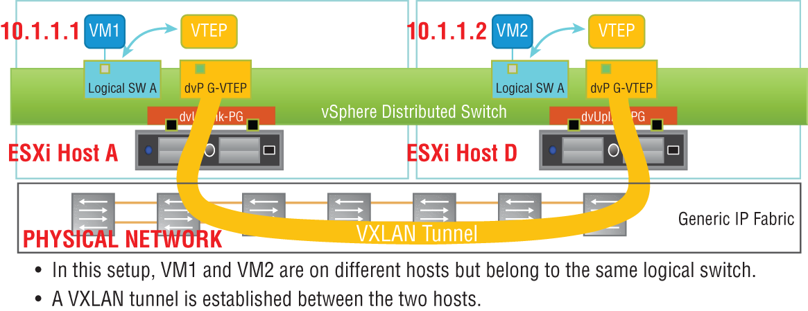
FIGURE 2.24 VXLANs tunnel through the physical network to allow traffic to other hosts.
VXLANs give the ability to tunnel through the physical network regardless of the complexities. Every ESXi host could be connected by only routers, and it would not matter. VLANs configured on switches in the physical network would not matter. This greatly simplifies the architecture since the physical network essentially is treated as a transport pipeline.
To provide the tunneling, an extra 50 bytes is added to an Ethernet frame (see Figure 2.25). Because of this, VMware recommends increasing the Maximum Transmission Unit (MTU) frame size to at least 1600 bytes. This is one thing that would need to potentially be changed in the physical environment. All the physical routers and switches would need to also support this minimum, but this is a very minor change and can be implemented in production without affecting traffic.

FIGURE 2.25 A 50-byte header containing VXLAN information is added to the front of a frame to be forwarded to another host.
Each ESXi host will have a VXLAN Tunnel Endpoint (VTEP). As an analogy, think of New York City as the physical network. The subway provides tunnels through the city. If you want to get from the Empire State Building to Times Square, all you need to know is the destination subway stop (see Figure 2.26). With VXLANs, you just need to know the IP address of the VTEP (subway stop) of the destination ESXi host (Times Square).

FIGURE 2.26 VTEPs are the tunnel endpoint IP addresses assigned to each host.
Each VTEP is configured as a separate VMKernel interface on the hosts and is assigned an IP address. When a packet leaves a VM on ESXi-Host1 destined for a VM on ESXi-Host3, the hypervisor of Host1 encapsulates the packet, adding the 50-byte header that contains the source and destination VTEP IP addresses. This is then forwarded out of the host into the physical network. The physical network knows how to reach each VTEP and treats the packet like any other. Once it gets to the destination host, the frame is decapsulated and the 50-byte outer header is stripped off. What's left is the original Ethernet frame, which the host then forwards to the destination VM.
NSX is agnostic to the underlay network topology. It only has two requirements: 1) IP connectivity and 2) an MTU size of at least 1600 bytes. For any network architect considering network upgrade options, this incredibly short and easy requirements list means that NSX can be immediately integrated.
Replication Modes for Traffic Going to Multiple Destinations
In the previous example, if we looked at the original packet that was generated by the source VM, we would find its IP address as the source and the other VM's IP address as the destination. This is a unicast packet, with a single destination.
However, consider a broadcast to all VMs on a single subnet. If there were VMs belonging to that subnet on hosts A, B, C, and D, how is that going to work when we send it through the physical network? The destination isn't one VTEP, it's three.
It's handled by replicating the packet, and there are three replication modes: unicast, multicast, and hybrid. By default, the logical switch within the host will inherit the mode configured for the entire transport zone (the group of ESXi hosts that can all communicate with one another). However, if desired, this can be overridden by manually making the change on the virtual switch.
Multicast Mode
If multicast replication mode is chosen, NSX needs to rely on the multicast routing abilities of the physical network (see Figure 2.27). This mode is specified in the IETF specifications, but this reliance on the physical network being configured in a specific way to handle multicast traffic means that the logical overlay and the physical underlay aren't truly decoupled.
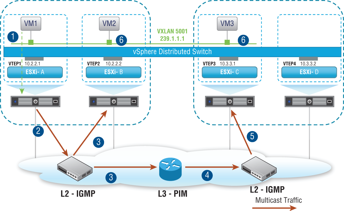
FIGURE 2.27 Multicast mode relies on multicast routing to be configured in the physical network.
Unicast Mode
Unicast mode allows for a true decoupling of the overlay and underlay. Based on the IP addresses of the VTEPs for each host, some VTEPs may belong to the same subnet. These ESXi hosts are seen as a single group. For example, group 1 might include ESXi hosts A and B (see Figure 2.28). They are addressed 10.2.2.1 and 10.2.2.2, respectively. They belong to the same subnet. Hosts C and D are addressed 10.3.3.1 and 10.3.3.2, respectively. They are in a separate group and share a subnet. For each group/subnet, a single ESXi host is chosen to be the Unicast Tunnel End Point (UTEP) for the group. The UTEP's job is to replicate the broadcast packet to all the hosts within its own group.

FIGURE 2.28 Unicast mode does not require the physical network to be configured for multicast routing.
VM1 on host A sends a broadcast. The broadcast is intended for every device on the 172.16.1.0 network. Host D has a VM with the address 172.16.1.4. Within the host group of A and B, say that host B is chosen as the UTEP. And within the host group of C and D, say host C is picked as the UTEP.
The packet flow would look like this: VM1 on host A, 172.16.1.1 sends a broadcast. Host A knows this is a multi-destination packet and sends it to host B. If other hosts existed in its group, host B would replicate the packet to those that have VMs in the same 172.16.1.0 subnet.
Host A also sends the packet to the other group's UTEP, host C. Host C, knowing that host D contains at least one VM in the 172.16.1.0 subnet, replicates the packet to host D where the VM4 172.16.1.4 receives it.
Hybrid Mode
As the name implies, hybrid mode is a hybrid between unicast and multicast modes. If a host needs to replicate a broadcast packet to other hosts in the same group, it uses one solution. But if the host needs to replicate the broadcast packet to hosts belonging to a different group, it uses a second solution.
- Solution 1: When Replicating a Packet to Other Hosts in Your Same Group The first group in our example consists of hosts A and B (in subnet 10.2.2.0). When host A needs to replicate a packet to B, its solution is to send it as an L2 multicast. If other hosts were part of the same group, they would also receive it.
- Solution 2: When Replicating a Packet to Other Hosts Belonging to a Different Group When host A (in subnet 10.2.2.0) needs to replicate a packet to C and D (in subnet 10.3.3.0), its solution is to send it as a unicast only to the Multicast Tunnel Endpoint for that group, host C (10.3.3.1)—see Figure 2.29. Then host C is responsible for replicating it to the other hosts in its group as an L2 multicast. In this example, it would multicast it to host D.
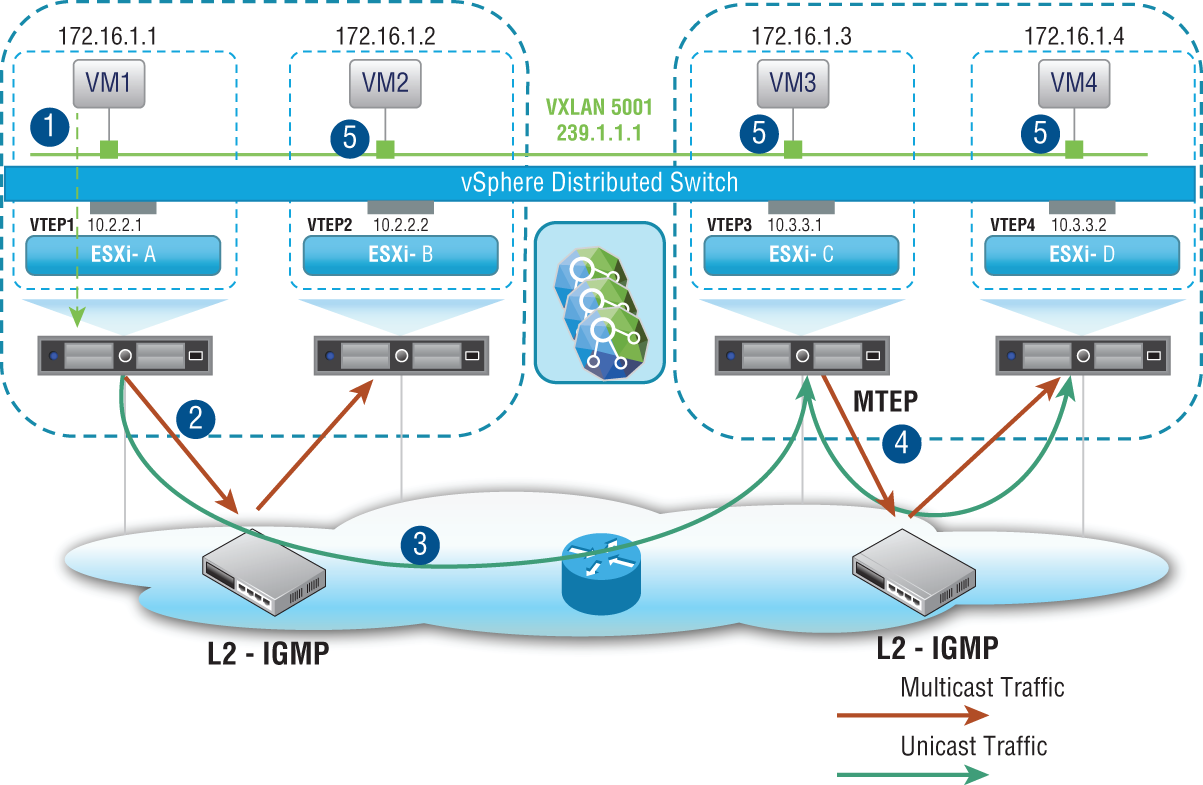
FIGURE 2.29 Hybrid mode multicasting to members of the same group, unicasting to the MTEP of a different group
Broadcast traffic isn't the only kind of multi-destination traffic. Broadcasts are intended for all devices in a given subnet. Another type of multi-destination traffic is an unknown unicast. This is what happens when a switch receives a frame with a destination MAC address but has no idea to which port to send it, so it floods it out all ports, and therefore it becomes multi-destination traffic. Another type of multi-destination traffic is a multicast. This traffic iintended for a specific group. For example, if you are familiar with the OSPF routing protocol, it works by sending information to other OSPF routers without bothering anyone else. When you configure OSPF, it automatically joins the OSPF group.
These different types of multi-destination traffic (broadcast, unknown unicast, and multicast) are sometimes referred to as BUM traffic. In the previous examples given, the initial traffic generated by the VM was in the form of a broadcast, but if the examples were unknown unicasts or multicasts, they would be handled identically depending on the chosen replication mode.
The Bottom Line
- Planes of Operation Traditional network devices operate autonomously, having the management, control, and data planes all contained within each. NSX moves the management plane to NSX Manager and the control plane to NSX Controllers.
- Master It What NSX component provides the data plane?
- NSX Data Appliance
- NSX Virtual Switch
- ESXi Host
- NSX Edge
- Master It What NSX component provides the data plane?
- NSX Controllers Instead of an active/backup design, each NSX Controller in a cluster is always active. This is so that they can slice and share the workloads.
- Master It When deploying NSX Controllers in production, how many should a cluster contain?
- Solution Three
- Software-Defined Data Center Terminology It's commonly thought that most data center traffic is between the data center and outside networks, when in reality, it is from one VM to another within the data center. Both types of traffic have specific SDDC terms to describe each.
- Master It East-West traffic refers to:
- Traffic within the data center
- Traffic between the data center and outside networks
- Traffic between the virtual and physical networks
- Master It East-West traffic refers to: