
2
Architecture of the Core Network
This is the first of two chapters that lay out the system architecture of 5G. We will begin by reviewing the architecture of the LTE evolved packet core, partly because it is still used by early 5G roll‐outs, and partly because it will act as an introduction to the 5G core. We will then move onto the 5G core network itself, covering its architecture and the roles of its most important network functions.
The main signalling protocol in the 5G core network is version 2 of the Hypertext Transfer Protocol (HTTP/2). That protocol is very different from the ones used by older mobile telecommunication systems, so we will review the protocol and provide some examples of the resulting signalling procedures. Several specifications are relevant to this chapter, but the most important is the stage 2 description of the 5G core network, Technical Specification (TS) 23.501 [1].
2.1 The Evolved Packet Core
2.1.1 Release 8 Architecture
Figure 2.1 shows the most important elements in the LTE evolved packet core (EPC) [2]. The different icons represent network elements that are used for data transport, signalling and information storage. An individual network might contain several instances of each one, both for geographical organization and for redundancy.
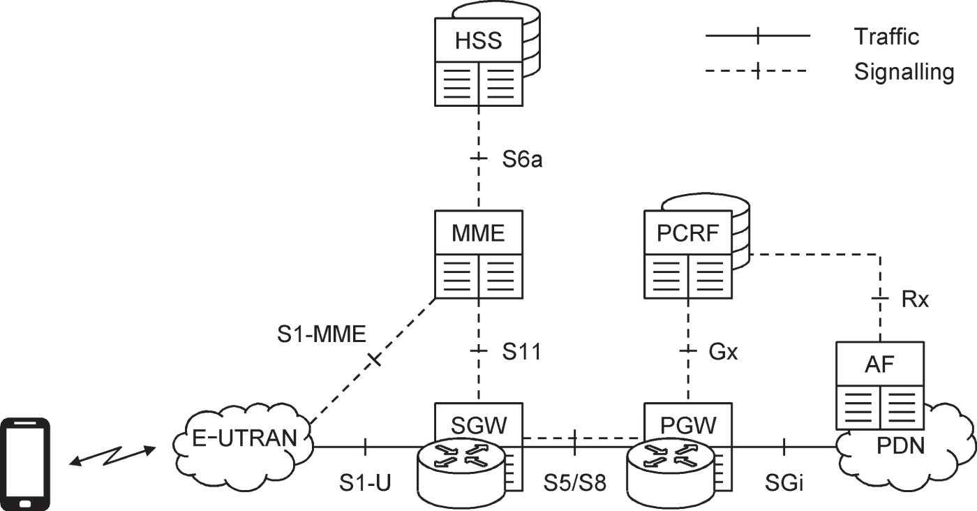
Figure 2.1 Architecture of the evolved packet core.
Source: Adapted from 3GPP TS 23.401.
The interfaces between network elements are more accurately known as reference points. We will stick to that terminology within this book to avoid confusion with the separate service‐based interfaces discussed later on. Solid lines denote reference points in the user plane which carry traffic, while dashed lines denote reference points in the control plane which carry signalling. Despite appearances, the reference points are not usually implemented as point‐to‐point connections: instead, they run over an underlying IP‐based transport network, in which routers use the network elements' IP addresses to deliver traffic and signalling messages between them.
Using the evolved packet core, the mobile connects with one or more external packet data networks (PDNs), with each connection made through a point of contact known as a packet data network gateway (PDN‐GW or PGW). The PDN gateway's role in the user plane is delivering incoming and outgoing traffic to and from the mobile. Its roles in the control plane are managing the mobile's communications with the data network and informing a separate charging system about the amount of traffic that the mobile has transferred.
A mobile is assigned a single serving gateway (SGW), which forwards the mobile's traffic between the radio access network and each of its PDN gateways. The mobile is also assigned a mobility management entity (MME), which is known as its serving MME. That device controls the high‐level operation of the mobile using two types of signalling message: mobility management signalling, which controls its communications with the evolved packet core, and session management signalling, which controls its communications with the packet data networks.
The home subscriber server (HSS) has two parts: a database that contains information about the network operator's subscribers, and a front end that presents the information to the other elements in the network. Finally, the policy and charging rules function (PCRF) determines sets of parameters that constrain the mobile's interactions with the network, which are known as network policies. These include the maximum data rate and end‐to‐end delay that a mobile will receive for a particular data stream, and the amount that the user will be charged. As part of that role, the PCRF can accept requests from external servers, known as application functions (AFs), to set up streams of traffic in the evolved packet core. In LTE, such requests are generally restricted to application functions that are controlled by the network operator itself, most often those in the operator's IP multimedia subsystem (IMS).
2.1.2 Control and User Plane Separation
In the original architecture for the evolved packet core, the PDN gateway carried out tasks in both the control and user planes. Although the serving gateway was mainly a user plane device, it also handled a few control plane tasks such as its own interactions with the charging system.
The control and user planes were split apart in a Release 14 work item known as control and user plane separation. In the resulting architecture [3], a PDN gateway control plane (PGW‐C) handles the signalling aspects of the PDN gateway and controls one or more PDN gateway user planes (PGW‐Us) that handle traffic. The serving gateway is divided in the same way. The architecture allows network operators to reap some of the benefits of software‐defined networking, anticipates the architecture of the 5G core network and eases subsequent interworking between the two.
2.2 The 5G Core Network
2.2.1 Representation Using Reference Points
Figure 2.2 shows the most important network functions in the 5G core network (5GC) [4]. Although the icons are the same as the ones used in Figure 2.1, the intention is to implement them using software, in the form of virtualized network functions that are running on general‐purpose hardware. As before, an individual network might contain several instances of each one.

Figure 2.2 Representation of the 5G core network using reference points.
Source: Adapted from 3GPP TS 23.501.
Using the 5G core network, the mobile can connect to one or more packet data networks (abbreviated in 5G as DN), for example the Internet, the IMS, or a low‐latency network for a private industrial client. Each connection is associated with a session management function (SMF). The SMF controls the mobile's interactions with the data network, communicates with the mobile by means of session management signalling and sends information about the mobile's data usage to a separate charging system. The SMF also controls one or more user plane functions (UPFs), which handle the user's traffic.
Each mobile is assigned an access and mobility management function (AMF), which is known as its serving AMF. The AMF controls the mobile's interactions with the 5G core by means of mobility management signalling, and relays session management signalling between the mobile and its respective SMFs. Both sets of messages are relayed by the next-generation radio access network (NG-RAN) over a reference point denoted N1, while the AMF communicates with the NG-RAN itself over a reference point denoted N2.
Unified data management (UDM) combines a subscriber database with a front end that presents the information to the other functions in the network. Finally, policy control functions (PCFs) supply a mobile's SMFs with network policies that relate to session management, for example the maximum data rate and the amount that the user will be charged, and supply its AMF with network policies that relate to mobility management, such as any restrictions on the mobile's movement. Interactions between the PCFs and external application functions are richer than in LTE, and are discussed in Chapter 15.
A comparison with LTE shows that the UDM, AMF and PCF have similar roles to the HSS, MME and PCRF, while the SMF and UPF are similar to the control and user planes of the serving and PDN gateways. The main distinction is that the mobile's session management signalling is handled by the SMF, not the AMF.
The remaining network functions are new to 5G. The network slice selection function (NSSF) determines the network slices with which the mobile will be registered and assigns a serving AMF to the mobile that supports those slices. The authentication server function (AUSF) helps the AMF during the security procedure of authentication.
2.2.2 Representation Using Service‐based Interfaces
Although the use of reference points is familiar from previous generations, the 5G core network is usually represented by means of service‐based interfaces in the architecture shown in Figure 2.3 [5,6]. In this representation, almost every network function is associated with a service‐based interface, on which it offers services to other network functions over a clearly defined application programming interface (API). Most of the signalling procedures in the 5G core are defined by means of service‐based interfaces: in contrast, the specifications hardly use the corresponding reference points at all.

Figure 2.3 Representation of the 5G core network using service‐based interfaces.
Source: Adapted from 3GPP TS 23.501.
On a service‐based interface, the network function offering the service is known as the network function producer, while the one using the service is the network function consumer. The producer's services are organized into two levels: a coarse organization into network function services, and a finer organization into individual service operations. Each operation is named using the scheme
Nnfname_ServiceName_ServiceOperation
, in which the three parts identify the service‐based interface, the network function service and the service operation respectively. For example, the UDM's interface includes the service operation
Nudm_SubscriberDataManagement_Get
, through which another network function can retrieve some or all of a user's subscription data.
Service‐based interfaces have been introduced for several reasons [7–9]. Firstly, the number of service‐based interfaces depends on the number of network functions in the 5G core, while the number of reference points potentially depends upon its square. By defining signalling procedures on service‐based interfaces, the number of procedures remains manageable, even if the number of network functions rises. Secondly, the use of service‐based interfaces promotes the re‐use of signalling procedures within the system, which in turn contributes to a cleaner system design. Thirdly, a service‐based interface is the architecture expected for communications between a software‐defined network and a third‐party application server over a northbound API. By following that architecture for its external signalling and using the same architecture internally, the Third Generation Partnership Project (3GPP) has adopted a consistent design throughout the 5G core.
Nevertheless, the use of service‐based interfaces is still incomplete. In particular, there are no service‐based interfaces for the radio access network and for the UPF: instead, those network functions continue to use custom signalling procedures that are defined on traditional reference points.
Figure 2.3 also introduces two new network functions. An individual network function can register itself with a network repository function (NRF), so that it can be discovered by other network functions within the 5G core. The 5G equipment identity register (5G‐EIR) acts as a database of lost or stolen mobiles, and handles the same tasks as the EIR from previous generations.
2.2.3 Data Transport
The connection between a mobile and an external data network is known as a protocol data unit session (PDU session) [10]. Figure 2.4 shows some example PDU sessions for a mobile that is connected to the Internet and the IMS.

Figure 2.4 PDU sessions and QoS flows.
Each PDU session is associated with one or more UPFs, which can take on various roles. A PDU session anchor is a point of contact between the data network and the 5G core. There is usually one anchor for each PDU session, but there may be more. There may also be intermediate UPFs (I‐UPFs), which forward traffic between the anchors and the radio access network.
Adding some more detail, the backhaul for each PDU session terminates in a single UPF, which might be acting as a PDU session anchor, an intermediate UPF or both. If the user is not roaming, then each PDU session is associated with a single SMF in Release 15, but can be associated with more than one SMF from Release 16.
A PDU session contains one or more quality of service flows (QoS flows), which have similar roles to the default and dedicated bearers from LTE. Each QoS flow is a set of data packets that have a defined set of QoS targets, for parameters such as data rate, error rate and end‐to‐end delay. One QoS flow is established when a PDU session is set up, for example a QoS flow carrying Internet traffic, or a QoS flow carrying high‐level signalling messages between the mobile and the IMS. Others, with different QoS targets, can be established later, for example a QoS flow carrying IMS voice traffic.
LTE only supported IP‐based data networks, such as the Internet. In contrast, 5G also supports data networks that use different communication protocols, for example Ethernet. That helps the system support machine‐type and low‐latency applications, in which the individual packets can be small and the impact of delivering large IP packet headers can be high.
2.2.4 Roaming Architectures
If the user is roaming, then the mobile, NG-RAN and AMF are always in the visited network, while the AUSF and UDM are always in the home network. There are then two ways to route the traffic in a particular PDU session.
Data communications with the Internet generally use home routed traffic (Figure 2.5). In that architecture, the PDU session anchor is in the user's home network and is controlled by a home SMF. The visited network contains an intermediate UPF, which shields the anchor from the need to know about the visited network's base stations, and is controlled by a visited SMF. The two networks communicate over an interface that is outside their control, for example an inter‐operator backbone known as the IP packet exchange (IPX) [11]. The signalling messages on that interface are secured by another network function, which is known as the security edge protection proxy (SEPP).
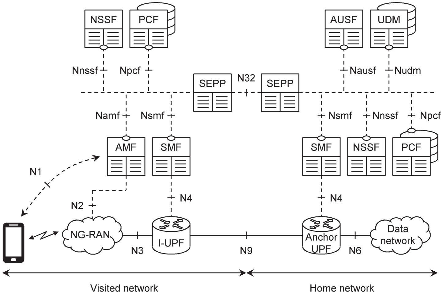
Figure 2.5 Roaming architecture using home routed traffic.
Source: Adapted from 3GPP TS 23.501.
When using home routed traffic, the home and visited networks both contain an NSSF, because the network slice's user plane lies within both networks. Similarly, both networks contain a PCF, so that they can both supply the relevant network policies for the mobile.
Local breakout (Figure 2.6) is valuable for communications with the IMS and essential for low‐latency roaming applications. In that architecture, the PDU session anchor is in the visited network, which allows a roaming user to place a local IP voice call without the need for the traffic to travel back to the home network. There is only one NSSF, which is in the visited network because the network slice's user plane only lies within that network. However, there is still a PCF in both networks, for the same reason as before.

Figure 2.6 Roaming architecture using local breakout.
Source: Adapted from 3GPP TS 23.501.
2.2.5 Data Storage Architectures
In the architectures described so far in this chapter, the UDM and PCF both had two components: databases containing structured data, in other words data whose structure is defined by the 3GPP specifications, and front ends. However, some of the information in those databases is shared. As shown in Figure 2.7, the databases can optionally be combined within a single network function, known as the unified data repository (UDR). The UDR can also be used by another new network function, the network exposure function (NEF), which acts as an additional point of contact between external third‐party application functions and the 5G core.
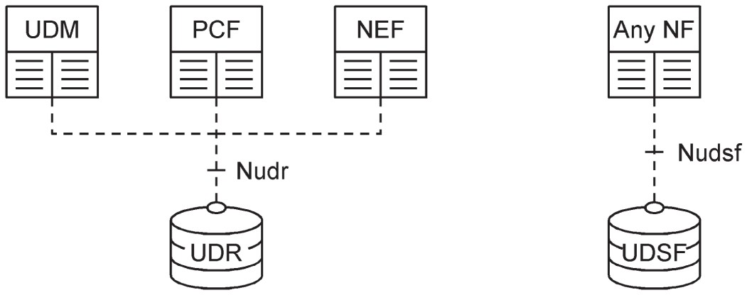
Figure 2.7 Data storage architectures.
Source: Adapted from 3GPP TS 23.501.
Network functions also store information about the mobiles that they are controlling. If that information is defined by the specifications, then it is known as a context. As an example, the AMF stores a user equipment (UE) context for each of its mobiles, which contains information such as the subscriber data that it has retrieved from the UDM, and the details of the mobiles' states. The network functions can also store information that is not defined by the specifications, such as operator‐specific configuration parameters.
Optionally, the network functions can store this information in a separate database known as an unstructured data storage function (UDSF). Depending on its implementation, one UDSF can store data from a single instance of a network function, from several instances of the same type of function or from network functions of different types.
2.2.6 Non‐3GPP Access to the 5G Core
Mobiles can access the 5G core network over a non‐3GPP access network, such as IEEE 802.11 WiFi. Release 15 supports access over an untrusted wireless network, in which the 5G core network assumes that the access network is insecure. Release 16 extends that support to trusted wireless networks and also to wireline access [12].
Non‐3GPP access has been supported by previous generations, but the 5G architecture is more closely aligned with the one for 3GPP access than before. Figure 2.8 shows the most important network functions in Release 15: the other functions from previous figures in this chapter are all retained.
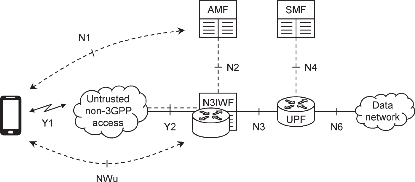
Figure 2.8 Architecture for non‐3GPP access to the 5G core network.
Source: Adapted from 3GPP TS 23.501.
In this architecture, the term 5G access network (5G‐AN) covers both 3GPP access networks, in other words the NG‐RAN, and non‐3GPP access networks such as WiFi. In both cases, the mobile is controlled by a serving AMF, and is authenticated by the AMF and AUSF. The AMF communicates with the mobile over the N1 reference point and communicates with the access network over N2, using the same signalling procedures as it does for 3GPP access.
There is one new network function. The non‐3GPP interworking function (N3IWF) terminates the N2 and N3 reference points, so as to act as an interface between the access network and the 5G core. It also secures the mobile's communications over the access network by establishing a secure tunnel to the mobile using signalling messages over a reference point denoted NWu. In Release 15, an individual PDU session traverses either a non‐3GPP access network or the NG‐RAN, but not both. More flexibility is introduced in Release 16 [13].
2.3 Network Areas, Slices and Identities
2.3.1 Network Identities
The 5G core network uses several different types of identity [14]. Some of these are inherited from previous generations, while others are new.
An operator's network is identified by a public land mobile network identity (PLMN‐ID). The PLMN‐ID comprises a three‐digit mobile country code (MCC), and a two or three‐digit mobile network code (MNC) that identifies the network within that country [15]. An external data network is identified by a data network name (DNN). That is identical to the access point name (APN) from previous generations: the only change is the name.
2.3.2 Network Slices
In 5G, a public land mobile network comprises a number of network slices, each of which is a virtual logical sub‐network running on shared physical hardware [16,17]. An individual network function does not have to support all of the network's slices: instead, it declares which slices it supports when registering with the network repository function.
When a mobile registers with the network, it does so with one or more of the network's slices. The mobile's AMF serves all the slices with which a mobile is registered, and the radio access network does so as well. In contrast, an individual PDU session lies in a single slice, so a mobile's SMFs and UPFs serve one slice each. Even so, a mobile can still connect to a particular data network through multiple slices by means of multiple PDU sessions.
Each type of network slice is identified by a field known as single network slice selection assistance information (S‐NSSAI). That has two components. The first is the 8‐bit slice/service type (SST), which defines the high‐level behaviour that the slice should deliver. Three values were standardized in Release 15 for the three main use cases of enhanced mobile broadband (eMBB), ultra‐reliable low‐latency communication (URLLC) and massive internet of things, (mIoT), while a fourth was added in Release 16 for vehicle‐to‐everything (V2X) communications. Network operators can also define other values of their own. The second component is an optional 24‐bit slice differentiator (SD), which distinguishes different types of slice that share the same SST. There are no standardized values, but network operators might use them to distinguish slices for different services, for example mobile broadband access to the Internet and to the IMS, or for different clients or devices.
In roaming scenarios, the home and visited networks can use the standardized values for the S‐NSSAI without the need for any further action. The two networks can also set up a conversion between any non‐standardized values as part of a service‐level agreement, which is implemented in the visited network's NSSF.
Network slice selection assistance information (NSSAI) is a list of S‐NSSAIs. There are a few varieties of NSSAI, but only three will be important for us. Firstly, the UDM stores a subscribed NSSAI for each user, which lists the types of slice that the user has subscribed to. Secondly, the mobile sends a requested NSSAI to the network, which lists the types of slice that it would like to register with. Thirdly, the AMF provides the mobile with an allowed NSSAI, which lists the types of slice that the mobile is actually registered with, and which it can use to establish a PDU session.
An individual network slice is known as a network slice instance and is identified using an operator‐specific character string known as the network slice instance identifier (NSI‐ID). A network operator can deploy multiple network slice instances that share the same S‐NSSAI but are distinguished using parameters such as their coverage area or the maximum number of mobiles that they support. The operator can set up, modify and tear down individual network slice instances using the network management system [18].
2.3.3 AMF Areas and Identities
AMFs are grouped together in two levels [19]. An AMF set is a group of AMFs which span the same geographical area and support the same set of network slices. In turn, an AMF region comprises one or more AMF sets, each of which might span a different geographical area and/or support a different set of network slices. AMF sets can overlap, in that one AMF can belong to multiple sets that have different geographical boundaries and/or different support for network slicing. Similarly, AMF regions can overlap, in that one AMF set can belong to multiple regions.
These areas are the basis of AMF identities. The 8‐bit AMF region ID uniquely identifies an AMF region within the network, while the 10‐bit AMF set ID uniquely identifies an AMF set within the region. In simple implementations, the 6‐bit AMF pointer identifies a single AMF within an AMF set. In more complex implementations, multiple AMFs can share the same AMF pointer if they store their data in the same unstructured data storage function, such that the mobile's exact choice of AMF is immaterial.
The AMF identifier (AMFI) comprises the AMF region ID, AMF set ID and AMF pointer, and identifies one or more AMFs within the network. Similarly, the globally unique AMF identifier (GUAMI) comprises the MCC, MNC and AMFI.
2.3.4 UE Identities
As in previous 3GPP systems, a 5G mobile has two components with different identities [20,21]. The mobile equipment is identified by a permanent equipment identifier (PEI). There are two slightly different forms of PEI, namely the 15‐bit international mobile equipment identity (IMEI) and the 16‐bit IMEI and software version number (IMEISV). The universal subscriber identity module is identified by the subscription permanent identifier (SUPI), which again has two forms: either the international mobile subscriber identity (IMSI) that was used for 3GPP access in previous generations, or the network access identifier (NAI) that was used for non‐3GPP access.
Networks avoid transmitting a mobile's SUPI over the air interface to prevent intruders from discovering it. Instead, a serving AMF identifies a mobile by assigning it a temporary identity. There are various types. The 32‐bit 5G temporary mobile subscriber identity (5G‐TMSI) uniquely identifies a mobile within a single AMF or within the group of AMFs that share the same AMF pointer. The 5G‐S‐TMSI comprises the AMF set ID, AMF pointer and 5G‐TMSI, and is used for procedures such as paging in which the mobile's AMF region is known. The 5G globally unique temporary identity (5G‐GUTI) comprises the GUAMI and the 5G‐TMSI, and is used for all other procedures.
In LTE, a mobile still had to transmit its IMSI or NAI occasionally, for example on the first use of the universal subscriber identity module (USIM) or after a database failure. That problem has been overcome in 5G by defining the subscription concealed identifier (SUCI), which contains the same information as the SUPI but is secured by means of public key encryption.
2.3.5 UE Registration Areas
A mobile's registration area is a geographical area through which the mobile is allowed to move, without the need to change its serving AMF or its allowed NSSAI, or, when on standby, without the need to inform the 5G core [22]. Registration areas are implemented by means of geographical regions known as tracking areas, which we will discuss further in Chapter 3. In the case of 3GPP access, each registration area is a list of tracking area identities. In the case of non‐3GPP access, the registration area is a single reserved tracking area identity which spans the whole of the non 3GPP access network.
2.4 State Diagrams
2.4.1 Registration Management
The mobile's behaviour is described using state diagrams. Each diagram has a number of different states, in which there are different objectives and different sets of procedures. The mobile and the network both have a copy of each state diagram, so that they can agree on the procedures that the mobile should use. The terminology is somewhat different in the stage 2 [23] and stage 3 [24] specifications for the 5G core network; we will stick to the simpler terminology from stage 2.
The first diagram (Figure 2.9) is the one for registration management. There are two states. In the state of RM‐REGISTERED, the mobile is in contact with the 5G core network and is registered with a serving AMF. The AMF knows something about the mobile's location and can reach the mobile through the 5G access network.
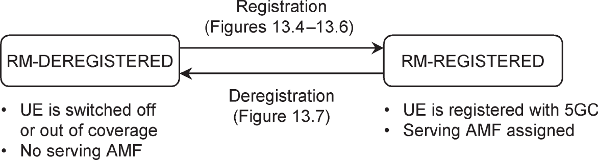
Figure 2.9 Registration management state diagram.
Source: Adapted from 3GPP TS 23.501.
In RM‐DEREGISTERED, the mobile is out of communication with the network, for example because it is switched off or in aeroplane mode. The network knows nothing about the mobile's location and is unable to reach it. However, the mobile and the old serving AMF both store some information about the mobile's previous registration, for example its temporary identities and security keys.
When the mobile switches on, it contacts the 5G core network in a signalling procedure known as registration, which moves it to the state of RM‐REGISTERED. Similarly, the mobile runs the procedure of deregistration before it switches off.
In early releases of LTE, a mobile always connected to a packet data network as part of the registration procedure to provide it with always‐on connectivity. That became optional in 3GPP Release 13 to help support machine‐type devices that might only communicate using mechanisms such as the short message service. In 5G, a PDU session is no longer established as part of registration: instead, it is always established in a separate signalling procedure. A mobile can therefore be registered with the 5G core without any PDU sessions and without any data network addresses, SMFs or UPFs.
2.4.2 Connection Management
The second diagram (Figure 2.10) is the one for connection management. There are two states which, except in transient situations, are best understood as sub‐states of RM‐REGISTERED. In the state of CM‐CONNECTED, the mobile is active. The serving AMF knows the mobile's master node, and can exchange mobile‐specific signalling messages with that node over the N2 reference point and with the mobile itself over N1. If the mobile has any PDU sessions, then it may also be able to exchange data with an external data network.

Figure 2.10 Connection management state diagram.
Source: Adapted from 3GPP TS 23.501.
In CM‐IDLE, the mobile is on standby. To reduce the amount of signalling and preserve the mobile's battery life, the AMF does not record the mobile's exact location: instead, the mobile can move throughout its registration area without the need to inform the 5G core. Only limited signalling is possible, and the mobile cannot exchange data with the outside world: if downlink data arrive, then the core network signals to the mobile throughout its registration area in a procedure known as paging. If the mobile wishes to contact the core network or to reply to a paging message, then it does so using the service request procedure, which takes it to the state of CM‐CONNECTED. The reverse procedure is known as access network release.
2.4.3 Non‐3GPP Access
In cases of non‐3GPP access, a mobile has two independent registration management states, one for 3GPP access through the NG‐RAN and one for non‐3GPP access. It also has two independent connection management states. Thus, for example, the mobile might be in RM‐REGISTERED and CM‐CONNECTED in respect of 3GPP access, but in RM‐REGISTERED and CM‐IDLE for non‐3GPP.
2.5 Signalling Protocols
2.5.1 Signalling Protocol Architecture
The 5G core network uses a number of signalling protocols, which are illustrated in Figure 2.11. Three of the protocols define signalling procedures between pairs of network functions over the underlying reference points. An SMF controls one or more UPFs by means of the packet forwarding control protocol (PFCP) [25], which is inherited from LTE Release 14. Similarly, the mobile communicates with the AMF and SMF using the 5G mobility management (5GMM) and 5G session management (5GSM) protocols [26].

Figure 2.11 Signalling protocols used by the 5G core network.
On the service‐based interfaces, the signalling protocol for the unstructured data storage function is not yet defined: any such implementations are proprietary. The other service‐based interfaces use version 2 of the Hypertext Transfer Protocol (HTTP/2), supplemented by the use of JavaScript Object Notation (JSON). Those protocols are also used on the N32 reference point between security edge protection proxies. The two protocols are unfamiliar in the context of a telecommunication system, so they are discussed in more detail later in this chapter.
The individual service‐based interfaces are then defined in a set of stage 3 specifications. The most valuable ones cover the AMF [27], SMF [28,29] and UDM [30], while others address the UDR [31–33], PCF [34–36], AUSF [37], NRF [38], 5G‐EIR [39], NSSF [40] and SEPP [41]. The underlying details are in References [42,43]. (We will cover a number of other specifications, including some more for the PCF, in Chapter 15.)
The core network's signalling messages are transported using an IP‐based protocol stack, the layer 4 protocol being the user datagram protocol (UDP) in the case of PFCP, and the transmission control protocol (TCP) in the case of HTTP/2. On the air interface, the 5GMM and 5GSM messages are transported using lower-level signalling protocols within the radio access network, which we will discuss as part of Chapter 3. Those low-level protocols are said to lie in the access stratum (AS), while the 5GMM and 5GSM protocols lie in the non-access stratrum (NAS).
2.5.2 Example Signalling Procedures
To illustrate the traditional use of signalling procedures over reference points, Figure 2.12 shows a simple procedure in which a UPF sets up an association with the SMF that will control it [44].
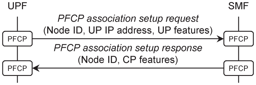
Figure 2.12 PFCP association setup procedure.
Before the procedure begins, the network management system has instantiated an instance of a UPF and has configured it with the IP addresses of one or more SMFs. (The UPF might also discover the SMFs by contacting the network repository function, as described later in this chapter.) To begin the procedure, the UPF contacts the SMF by sending it a message known as a PFCP association setup request. In that message, the UPF states its identity, includes the IP address that it uses for data transport and notes any optional features that it supports. The SMF replies with a PFCP association setup response, which includes its own identity and optional features. Once the procedure has completed, the SMF can instruct the UPF to set up, modify or tear down the user planes of individual PDU sessions, by means of further signalling procedures.
2.6 The Hypertext Transfer Protocol
2.6.1 HTTP/1.1 and HTTP/2
HTTP is the protocol used for information retrieval on the World Wide Web, for example to download information from a web server. 3GPP adopted the protocol for signalling on the 5G core network's service‐based interfaces for three main reasons [45]. Firstly, the use of a service‐based architecture is implicit in the design of HTTP. Secondly, its widespread use outside telecommunications eases deployment and helps with future‐proofing. Thirdly, HTTP is widely used for communications between software‐defined networks and third‐party application functions over the networks' northbound APIs. By using that protocol for both external and internal signalling, 3GPP has again adopted a consistent design throughout the 5G core.
In HTTP, a resource is an item of information that can be named. The information could be static, for example an image or text file, or dynamic, such as “Today's BBC news.” Its name is known as a uniform resource identifier (URI), while a uniform resource locator (URL) combines the URI with a means of locating the information. The distinction between the two is a subtle one [46]: consistent with the 3GPP specifications, we will refer to the names as URIs.
In a typical signalling transaction, a client composes an HTTP request for the information that is held at a particular URI. A domain name server (DNS) returns the IP address of a server where the information can be found, and the client sends the request there. The server replies with an HTTP response, together with data that represent the information in a suitable format. Examples include a web page that is written using Hypertext Markup Language (HTML), or a Portable Document Format (PDF) file.
The most familiar version is HTTP/1.1, introduced in 1999 [47–52]. HTTP/1.1 is a text protocol in which there is nothing to distinguish one character from another. To avoid any risk of confusion, individual requests and responses have to be sent in series, which increases the time required for information retrieval. That in turn triggers a risk of head‐of‐line blocking, in which a problem with an early request prevents completion of the ones that follow. Although there are ways to work around these shortcomings [53], none is entirely effective.
HTTP/2, introduced in 2015, has two protocol layers [54,55]. The upper data layer is similar to version 1.1 but has a slightly different syntax. The lower framing layer converts the text and any associated data into binary frames, with each frame labelled to distinguish one request and response from another. That allows requests and responses to be sent in parallel, and helps to overcome the shortcomings of version 1.1. Because of these enhancements, the protocol chosen for the 5G core network is HTTP/2.
2.6.2 Representational State Transfer
Representational state transfer (REST) is a set of architectural principles that has been widely adopted in the design and implementation of the World Wide Web [56]. At least in part, 3GPP has followed these principles in the design of the 5G core network [57].
REST uses a client–server architecture, in which a client sends a request to a server, the server returns an immediate response and there is a clear division of responsibilities between the two. The architecture is layered, so that the client knows nothing about the internal details of the server. 3GPP has followed both of these principles in the design of the 5G core network. The roles of client and server are usually filled by the network function consumer and producer respectively, although those roles are reversed in the procedures for subscription and notification that we will discuss at the end of this chapter.
In REST, the client and server interact by manipulating resources that are held by the server. 3GPP has followed this principle wherever possible, a decision that is key to understanding the operation of the 5G core. Most of the 5G network function services are implemented using a set of database‐style operations, often abbreviated as CRUD, which create, read, update and delete resources that are held by the server. That viewpoint is very different from the traditional use of signalling procedures over reference points, so we will illustrate it in more detail here. However, it has not proved possible to model every network function service in this way, so some have been implemented differently by means of customized operations.
REST is intended to be stateless, such that a server can store details about a client in a separate database but otherwise does not remember anything about a client's requests. Instead, each individual request contains all the information needed to understand it. Although the 5G core network does not follow this principle in full, it has been used to guide certain aspects of system design. If, for example, an AMF stores the details of its mobiles in a separate unstructured data storage function, then the AMF can be made stateless, and the mobile can communicate with any AMF that can retrieve those details.
In its last two principles, REST allows a client to cache responses from the server for later use, and to extend its functionality using code in the form of applets or scripts. The 5G core network occasionally uses caching, but otherwise these principles have not been adopted by 3GPP.
2.6.3 The HTTP/2 Data Layer
Figure 2.13 shows a simple example of an HTTP/2 request and response. An HTTP/2 request begins with four pseudo‐headers, which replace the start line used by HTTP/1.1. Three of those pseudo‐headers contain the different components of the URI.
:scheme
defines a naming scheme for the URI, and is usually the same as the name of the associated signalling protocol.
:authority
contains the domain name or IP address of the server that hosts the URI, together with an optional TCP port number. Finally,
:path
identifies an individual resource within the host.
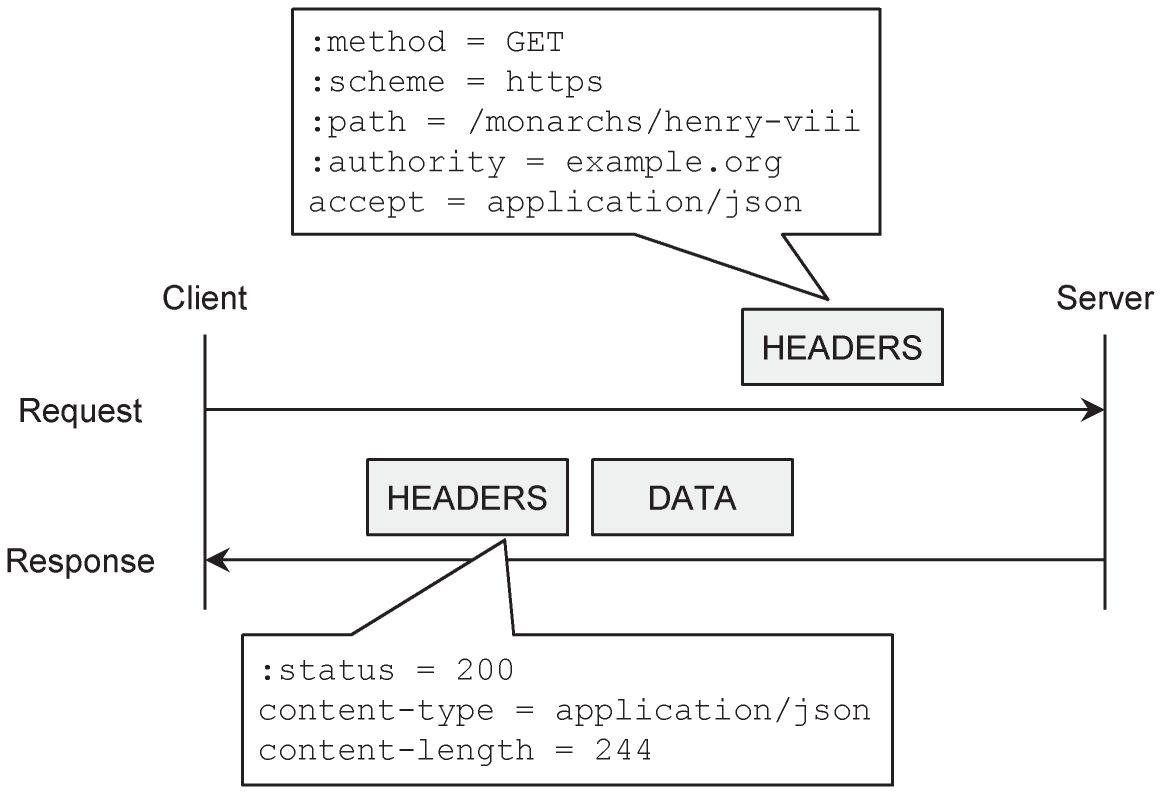
Figure 2.13 Example of an HTTP/2 request and response.
The fourth pseudo‐header,
:method
, identifies the request. Although HTTP/2 supports several different methods, the 5G core network only uses five, for the tasks that are listed in Table 2.1 [58]. Most of these tasks are database‐style operations to create, read, update and delete a resource upon a server. POST is also used for custom procedures that cannot easily be modelled using database operations, and for notifications from a network function producer back to a consumer. Various HTTP/2 header fields supply additional details about the request.
Table 2.1 HTTP/2 methods used by the 5G core network.
| Method | Usage in the 5G core network | Additional information |
|---|---|---|
| DELETE | Delete a resource. | None |
| GET | Read a representation of a resource. | URI query parameters |
| PATCH | Partially update a resource. | JSON modifications |
| POST | Create a new resource, with the URI chosen by the server. Notify a client in response to a previous subscription. Ask the server to carry out a custom operation. |
JSON content |
| PUT | Create a new resource, with the URI chosen by the client. Replace a resource. |
JSON content |
The client can send information to the server in two ways. In the case of a GET request, the client can provide more details about the data than are required by extending the URI using query parameters. In the cases of PATCH, POST and PUT, the client supplies data of its own, in the same way as for the server's responses.
An HTTP/2 response begins with a single pseudo‐header,
:status
, which provides a three‐digit code that indicates the nature of the response. The first digit can have five values: 1 indicates a provisional response; 2 indicates success; 3 asks the client to take further action, for example by contacting a different host; while 4 and 5 indicate errors on the client and server respectively. Each individual response code is associated with a text description, for example
200 OK
. Those descriptions are explicitly included in HTTP/1.1 responses, but are omitted from HTTP/2.
In the example in Figure 2.13, the client is requesting information from the server by means of an HTTP/2 GET. The framing layer converts the request to an HTTP/2 frame known as HEADERS, and converts the response in a similar way. The response frame is followed by a second HTTP/2 frame known as DATA, which contains the requested information.
2.6.4 JavaScript Object Notation (JSON)
On the World Wide Web, HTTP transfers data between clients and servers using formats such as HTML web pages and PDF files. In the 5G core network, the data simply comprise parameters that the client and server both understand. The data are most often structured by means of a standard known as JavaScript Object Notation (JSON), which includes formatting rules for logical values, numbers, character strings, objects and arrays [59]. Figure 2.14 shows a simple example.

Figure 2.14 Example of a JSON object.
There are two main variations. Firstly, the content for an HTTP/2 PATCH request is written using standards known as JSON Patch [60] and JSON Merge Patch [61]. These express modifications that the client wishes to apply to a JSON document, the main distinction being that JSON Patch allows modifications to the individual elements in an array, whereas JSON Merge Patch does not. Secondly, network functions sometimes exchange content by means of binary encoded data. For example, the SMF uses binary coding to send 5G session management signalling messages to the AMF, which relays them transparently to the mobile.
2.7 Example Network Function Services
2.7.1 Network Function Service Registration
To illustrate the implementation of network function services, Figure 2.15 shows the procedure in which a newly instantiated network function registers itself with an NRF. The example is for a registering AUSF, but the procedure for another type of network function would be the same.

Figure 2.15 Network function service registration procedure.
Source: Adapted from 3GPP TS 29.510.
The specifications define the procedure in two contrasting ways. The stage 2 specification defines it in terms of network function service operations: the AUSF requests the
NFRegister
operation from the
NFManagement
service in the NRF, and states its capabilities by supplying a network function profile [62]. The stage 3 specification then defines the HTTP implementation: the AUSF sends an HTTP PUT request to the NRF, which asks it to create a new resource at a URI that the AUSF supplied [63].
In common with all the network function services in the 5G core network, the URI has the following structure, in which the quantities in curly brackets are to be replaced with the appropriate text [64]:
{apiRoot}/{apiName}/{apiVersion}/{apiSpecificResourceUriPart}
Here,
{apiRoot}
contains two of the HTTP/2 pseudo‐headers, namely the scheme and the authority. The scheme is either
http://
or
https://
, depending on the choice of security protocol. By default, the authority for an NRF is
nrf.5gc.mnc{MNC}.mcc{MCC}.3gppnetwork.org
, where
{MNC}
and
{MCC}
are the mobile network and mobile country codes respectively [65]. (An operator can set up a different authority for the NRF by means of the network management system.)
{apiName}
is the name of the network function service's API, in this case
nnrf‐nfm
, while
{apiVersion}
is its major version number, currently
v1
. Finally,
{apiSpecificResourceUriPart}
is specific to the network function service operation. In this case, it is
nf‐instances/{nfInstanceID}
, where
{nfInstanceID}
is a 128‐bit Universally Unique Identifier (UUID) version 4 [66], which is supplied by the registering network function, and which should be unique within the network. Bringing all of these components together, the following is an example URI for the network function service registration procedure:
https://nrf.5gc.mnc13.mcc901.3gppnetwork.org /nnrf-nfm/v1/nf-instances/4947a69a-f61b-4bc1-b9da-47c9c5d14b64
The AUSF supplies its network function profile as data that are formatted using JSON. The profile includes the unique identifier defined above, the type of network function (in this case, AUSF) and its status (either registered or suspended). It also includes the network identity, the network slices that the AUSF supports, its priority and capacity relative to other network functions of the same type, and its domain name or IP address.
The NRF replies with the response
201 Created
, which confirms that the URI has been created. In its own JSON data, the NRF echoes back the network function profile and supplies a heartbeat timer. Later, the AUSF can update its profile by sending an HTTP PATCH to the same URI that it used earlier. It also contacts the NRF if the heartbeat timer expires, to confirm that it is still available.
2.7.2 Network Function Service Discovery
Once a network function has registered with the NRF, it can be discovered by another network function, for example by an AMF. The procedure is illustrated in Figure 2.16. To avoid clutter, the figure only shows the name of the network function service operation, the HTTP method and response code, the
{apiSpecificResourceUriPart}
field from the URI, and the most important data. That convention is consistent with the stage 3 specifications for 5G, and will be followed throughout the rest of the book.

Figure 2.16 Network function service discovery procedure.
Source: Adapted from 3GPP TS 29.510.
To ask for the details of any registered AUSFs, the AMF requests the
NFDiscover
operation from the
NFDiscovery
service in the NRF [67]. That operation is implemented as an HTTP GET [68]. The URI has the same structure as before: the
{apiName}
field is
nnrf‐disc
, and
{apiSpecificResourceUriPart}
is
nf‐instances?<query parameters>
. The query parameters supply further details about the request: they include the types of the two network functions, their two PLMN identities and the network slices that the AUSF should support.
The NRF replies with the HTTP response
200 OK
. In its JSON data, the NRF lists the profiles of AUSFs that match the request, and includes a validity period that states how long those profiles can be cached.
Assisted by the priority and capacity fields from their network function profiles, the AMF selects one of the matching AUSFs, sets up TCP and HTTP/2 connections with it, and requests the appropriate service operation. In the corresponding URI, the authority part of
{apiRoot}
is the domain name or IP address from the network function profile, while the fields
{apiName}
and
{apiSpecificResourceUriPart}
are defined in the appropriate stage 3 specification.
To support roaming mobiles, the AMF may have to discover an instance of an AUSF in a different network. To do so, the AMF sends its request to an NRF in its own network, which forwards the request to a second NRF in the destination network. On receiving the response, the AMF can contact the selected AUSF directly.
2.7.3 Network Function Service Subscription and Notification
To supplement the discovery procedure, a network function can ask to be notified if the registration details of another network function change. Figure 2.17 shows the procedure, once again for the example of an AMF and an AUSF.

Figure 2.17 Procedures for network function service subscription and notification.
Source: Adapted from 3GPP TS 29.510.
The AMF begins by requesting the
NFStatusSubscribe
operation from the NRF's
NFManagement
service [69]. That operation is implemented as an HTTP POST to the URI whose
{apiSpecificResourceUriPart}
is
../subscriptions
, which asks the NRF to create a child resource of that URI to handle the new subscription [70]. The AMF supplies further details by means of JSON data. These include the type of network function being monitored, the target network identity and a list of events that are of interest (namely registration, deregistration and/or modification). The AMF also supplies a notification URI, also known as a callback URI, on which it would like to be notified if one of those events takes place.
The NRF replies with the HTTP response
201 Created
. In its JSON data, the NRF echoes back the original subscription data, and supplies a subscription identity that completes the newly created child resource. (The AMF can delete the subscription whenever it needs to by sending an HTTP DELETE to that resource.)
Later, an AUSF might update its registration data in a way that matches the subscription. The NRF reacts by requesting the
NFStatusNotify
operation from its
NFManagement
service, which is implemented as an HTTP POST to the notification URI that the AMF supplied earlier [71]. In its JSON data, the NRF states the event that triggered the notification and supplies the updated network function profile. The AMF acknowledges with the HTTP response
204 No Content
.
It is worth noting that the 5G core network implements notifications differently from other service operations, in three ways. Firstly, the network function producer (in this case, the NRF) is acting as the client, not as the server. As a result, the service operation forms part of the client's API, not the server's. Finally, the URI is supplied by the network function consumer during the earlier subscription and is not defined by the API itself.
References
- 1 3GPP TS 23.501 (2019) System architecture for the 5G system (5GS); Stage 2 (Release 15), December 2019.
- 2 3GPP TS 23.401 (2019) General Packet Radio Service (GPRS) enhancements for Evolved Universal Terrestrial Radio Access Network (E‐UTRAN) access (Release 15), December 2019, Sections 4.2, 4.4.
- 3 3GPP TS 23.214 (2018) Architecture enhancements for control and user plane separation of EPC nodes; Stage 2 (Release 15), December 2018.
- 4 3GPP TS 23.501 (2019) System architecture for the 5G system (5GS); Stage 2 (Release 15), December 2019, Sections 4.2, 6.2.
- 5 3GPP TS 23.501 (2019) System architecture for the 5G system (5GS); Stage 2 (Release 15), December 2019, Section 4.2, Annex A.
- 6 3GPP TS 23.502 (2019) Procedures for the 5G system (5GS); Stage 2 (Release 15), December 2019, Annex A.
- 7 3GPP TR 23.799 (2016) Study on architecture for next generation system (Release 14), December 2016, Section 8.7.
- 8 Guttman, E. and Ali, I. (2018). Path to 5G: a control plane perspective. Journal of ICT Standardization 6 (1 and 2): 87–100.
- 9 Mayer, G. (2018). RESTful APIs for the 5G service based architecture. Journal of ICT Standardization 6 (1 and 2): 101–116.
- 10 3GPP TS 23.501 (2019) System architecture for the 5G system (5GS); Stage 2 (Release 15), December 2019, Sections 5.6.1, 5.7.1.
- 11 GSMA IR.34 (2018) Guidelines for IPX provider networks, Version 14.0.
- 12 3GPP TR 23.716 (2018) Study on the wireless and wireline convergence for the 5G system architecture (Release 16), December 2018.
- 13 3GPP TR 23.793 (2018) Study on access traffic steering, switch and splitting support in the 5G system architecture (Release 16), December 2018.
- 14 3GPP TS 23.501 (2019) System architecture for the 5G system (5GS); Stage 2 (Release 15), December 2019, Section 5.9.
- 15 Mobile Country Codes (MCC) and Mobile Network Codes (MNC). http://www.mcc-mnc.com (accessed 18 January 2020).
- 16 3GPP TS 23.501 (2019) System architecture for the 5G system (5GS); Stage 2 (Release 15), December 2019, Section 5.15.
- 17 3GPP TS 23.003 (2019) Numbering, addressing and identification (Release 15), September 2019, Section 28.4.
- 18 3GPP TS 28.541 (2019) Management and orchestration; 5G Network Resource Model (NRM); Stage 2 and stage 3 (Release 15), December 2019, Section 6.
- 19 3GPP TS 23.003 (2019) Numbering, addressing and identification (Release 15), September 2019, Sections 2.10.1, 28.3.2.5.
- 20 3GPP TS 23.003 (2019) Numbering, addressing and identification (Release 15), September 2019, Sections 2.2A, 2.2B, 2.10, 2.11, 6.4.
- 21 3GPP TS 33.501 (2019) Security architecture and procedures for 5G system (Release 15), December 2019, Section 6.12.
- 22 3GPP TS 23.501 (2019) System architecture for the 5G system (5GS); Stage 2 (Release 15), December 2019, Section 5.3.2.3.
- 23 3GPP TS 23.501 (2019) System architecture for the 5G system (5GS); Stage 2 (Release 15), December 2019, Section 5.3.
- 24 3GPP TS 24.501 (2019) Non‐access‐stratum (NAS) protocol for 5G system (5GS); Stage 3 (Release 15), December 2019, Sections 3.1, 5.1.3.
- 25 3GPP TS 29.244 (2019) Interface between the control plane and the user plane nodes; Stage 3 (Release 15), December 2019.
- 26 3GPP TS 24.501 (2019) Non‐access‐stratum (NAS) protocol for 5G system (5GS); Stage 3 (Release 15), December 2019.
- 27 3GPP TS 29.518 (2019) 5G system; Access and mobility management services; Stage 3 (Release 15), December 2019.
- 28 3GPP TS 29.502 (2019) 5G system; Session management services; Stage 3 (Release 15), December 2019.
- 29 3GPP TS 29.508 (2019) 5G system; Session management event exposure service; Stage 3 (Release 15), December 2019.
- 30 3GPP TS 29.503 (2019) 5G system; Unified data management services; Stage 3 (Release 15), December 2019.
- 31 3GPP TS 29.504 (2019) 5G system; Unified data repository services; Stage 3 (Release 15), December 2019.
- 32 3GPP TS 29.505 (2019) 5G system; Usage of the unified data repository services for subscription data; Stage 3 (Release 15), December 2019.
- 33 3GPP TS 29.519 (2019) 5G system; Usage of the unified data repository service for policy data, application data and structured data for exposure; Stage 3 (Release 15), December 2019.
- 34 3GPP TS 29.507 (2019) 5G system; Access and mobility policy control service; Stage 3 (Release 15), December 2019.
- 35 3GPP TS 29.512 (2019) 5G system; Session management policy control service; Stage 3 (Release 15), December 2019.
- 36 3GPP TS 29.525 (2019) 5G system; UE policy control service; Stage 3 (Release 15), December 2019.
- 37 3GPP TS 29.509 (2019) 5G system; Authentication server services; Stage 3 (Release 15), October 2019.
- 38 3GPP TS 29.510 (2019) 5G system; Network function repository services; Stage 3 (Release 15), December 2019.
- 39 3GPP TS 29.511 (2019) 5G system; Equipment identity register services; Stage 3 (Release 15), December 2019.
- 40 3GPP TS 29.531 (2019) 5G system; Network slice selection services; Stage 3, (Release 15), September 2019.
- 41 3GPP TS 29.573 (2019) 5G system; Public land mobile network (PLMN) Interconnection; Stage 3 (Release 15), October 2019.
- 42 3GPP TS 29.500 (2019) 5G system; Technical realization of service based architecture; Stage 3 (Release 15), September 2019.
- 43 3GPP TS 29.501 (2019) 5G system; Principles and guidelines for services definition; Stage 3 (Release 15), December 2019.
- 44 3GPP TS 29.244 (2019) Interface between the control plane and the user plane nodes; Stage 3 (Release 15), December 2019, Sections 6.2.6.3, 7.4.4.1, 7.4.4.2.
- 45 3GPP TS 29.891 (2017) 5G system – Phase 1; CT WG4 aspects (Release 15), December 2017, Section 11.3.1.2.
- 46 Miessler, D. (2019) What's the difference between a URI and a URL? https://danielmiessler.com/study/difference-between-uri-url (accessed 18 January 2020).
- 47 IETF RFC 7230 (2014) Hypertext Transfer Protocol (HTTP/1.1): Message syntax and routing.
- 48 IETF RFC 7231 (2014) Hypertext Transfer Protocol (HTTP/1.1): Semantics and content.
- 49 IETF RFC 7232 (2014) Hypertext Transfer Protocol (HTTP/1.1): Conditional requests.
- 50 IETF RFC 7233 (2014) Hypertext Transfer Protocol (HTTP/1.1): Range requests.
- 51 IETF RFC 7234 (2014) Hypertext Transfer Protocol (HTTP/1.1): Caching.
- 52 IETF RFC 7235 (2014) Hypertext Transfer Protocol (HTTP/1.1): Authentication.
- 53 Stenberg, D. (2019) HTTP2 explained. https://http2-explained.haxx.se (accessed 18 January 2020).
- 54 IETF RFC 7540 (2015) Hypertext Transfer Protocol Version 2 (HTTP/2).
- 55 IETF RFC 7541 (2015) HPACK: Header compression for HTTP/2.
- 56 Fielding, R.T. (2000) Architectural styles and the design of network‐based software architectures. Doctoral Thesis, University of California.
- 57 3GPP TS 29.891 (2017) 5G system – Phase 1; CT WG4 aspects (Release 15), December 2017, Section 6.2.2.4.
- 58 3GPP TS 29.501 (2019) 5G system; Principles and guidelines for services definition; Stage 3 (Release 15), December 2019, Section 4.6.
- 59 IETF RFC 8259 (2017) The JavaScript Object Notation (JSON) data interchange format.
- 60 IETF RFC 6902 (2013) JavaScript Object Notation (JSON) patch.
- 61 IETF RFC 7396 (2014) JSON merge patch.
- 62 3GPP TS 23.502 (2019) Procedures for the 5G system (5GS); Stage 2 (Release 15), December 2019, Section 4.17.1.
- 63 3GPP TS 29.510 (2019) 5G system; Network function repository services; Stage 3 (Release 15), December 2019, Sections 5.2.2.2, 6.1.3.3.3.2.
- 64 3GPP TS 29.501 (2019) 5G system; Principles and guidelines for services definition; Stage 3 (Release 15), December 2019, Section 4.4.
- 65 3GPP TS 23.003 (2019) Numbering, addressing and identification (Release 15), September 2019, Section 28.3.2.3.
- 66 IETF RFC 4122 (2005) A Universally Unique IDentifier (UUID) URN namespace.
- 67 3GPP TS 23.502 (2019) Procedures for the 5G system (5GS); Stage 2 (Release 15), December 2019, Section 4.17.4.
- 68 3GPP TS 29.510 (2019) 5G system; Network function repository services; Stage 3 (Release 15), December 2019, Sections 5.3.2.2, 6.2.3.2.3.1.
- 69 3GPP TS 23.502 (2019) Procedures for the 5G System (5GS); Stage 2 (Release 15), December 2019, Section 4.17.7.
- 70 3GPP TS 29.510 (2019) 5G system; Network function repository services; Stage 3 (Release 15), December 2019, Sections 5.2.2.5, 6.1.3.4.3.1.
- 71 3GPP TS 29.510 (2019) 5G system; Network function repository services; Stage 3 (Release 15), December 2019, Sections 5.2.2.6, 6.1.5.2.