
20
Release 16 and Beyond
In this final chapter, we will address the enhancements that are being made to the 5G system as part of Releases 16 and 17. The main topics include vehicle communications, location services, integrated access and backhaul, non‐terrestrial networks and massive machine‐type communications. We will also address a number of other enhancements towards the end of the chapter, and proposals for the longer term.
20.1 Vehicle‐to‐everything (V2X) Communications
20.1.1 Introduction
Vehicle‐to‐everything (V2X) communication refers to the exchange of information to and from a road vehicle. Such communication is part of an intelligent transport system (ITS), in other words a system in which information and communication technologies are applied in the field of road transport; it is often used to support the operation of driverless cars and other autonomous vehicles. The term everything covers communications with other vehicles (V2V), pedestrians (V2P), servers based in the network (V2N) and infrastructure elements (V2I) that are known as roadside units (RSUs).
LTE was enhanced to offer basic support for vehicle communication as part of 3GPP Release 14 [1,2]. However, that was limited by LTE's capabilities for data rate, latency and reliability, and simply allows vehicles to exchange information such as their position, speed and direction of travel, and to disseminate urgent messages such as a warning of a possible collision.
5G is enhanced to support vehicle communications as part of 3GPP Release 16 [3,4], in which the greater capabilities of 5G allow it to support a wider range of applications. There are four new categories. In an application known as extended sensors, vehicles can exchange information that they have gathered from sensors such as video cameras. That extends their knowledge of the surrounding environment and improves the driving experience, for example by allowing a vehicle to brake more gently if a queue appears in front of another vehicle further ahead. In a second application known as advanced driving, nearby vehicles use that information to share their driving intentions and coordinate their movements, so as to support semi‐automated or fully automated driving. Vehicle platooning allows a lead vehicle to control a convoy of other vehicles that are behind it. The separation between successive vehicles is limited by computational delays and by the latencies within the communication system, and can be much shorter than it is in traditional driving. Finally, remote driving allows a vehicle to be controlled from a distance, either by a remote driver or by a V2X application.
To help support the development of autonomous vehicles, SAE International has defined six levels of driving automation, which range from no automation (level 0) to full automation (level 5) [5]. The 5G system is intended to support all of these automation levels.
20.1.2 Architectural Enhancements
As part of Release 14, the architecture of LTE was enhanced to allow external V2X applications to communicate with the mobile and with the evolved packet core [6,7]. The architecture supports device‐to‐device communications over an air interface known as the sidelink, which had previously been introduced to LTE in Release 12.
5G is enhanced in a similar way as part of Release 16 [8,9]. Figure 20.1 shows the high‐level architecture, on the assumption that the mobile is not roaming. The V2X application server runs vehicle‐related applications and acts as an application function towards the 5G core network. PC5 is the air interface's sidelink, which is discussed in more detail in Section 20.1.3. V1 and V5 are reference points within the application layer, which the air interface transports using the Uu and PC5 interfaces respectively. The lower parts of V1 and V5 are specified in the case of LTE [10,11], but they are currently unspecified in the case of 5G.
Figure 20.2 shows more details of the application server's interactions with the 5G core. The application server exchanges information about the mobile's V2X communications with the network exposure function (NEF), in a similar way to the interactions that we introduced in Chapter 15. The policy control function (PCF) determines the mobile's V2X configuration parameters, taking on the role of the V2X control function from LTE. The access and mobility management function (AMF) conveys the relevant parameters to the mobile, using the procedures for the delivery of UE policy data after registration.
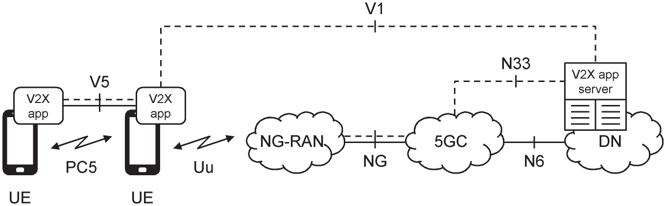
Figure 20.1 Architecture for vehicle‐to‐everything (V2X) communications.
Source: Adapted from 3GPP TS 23.287.

Figure 20.2 Representation of the V2X application server's interactions with the 5G core, using reference points.
Source: Adapted from 3GPP TS 23.287.
20.1.3 Device‐to‐device Communications
Originally, the LTE sidelink was introduced to support mission‐critical communications (MCCs) in a public safety network. Using the sidelink, two devices can continue communicating if they are outside the coverage area of the network, or if the base stations have been taken down by the very situation that triggered the emergency. Later, the LTE sidelink was enhanced to support the more stringent requirements of vehicle communications, such as the high Doppler shifts that result from fast‐moving vehicles. In the case of the 5G sidelink, vehicle communications is the initial motivation.
The 5G sidelink is closely based on the designs for the uplink and downlink [12-14]. It supports both of the 5G frequency ranges, although the only frequency bands defined at the time of writing are bands n38 and n47, the second of which encompasses the bands defined for intelligent transport systems in Europe and the USA. The sidelink supports the same subcarrier spacings that the uplink and downlink use for data, namely 15, 30 and 60 kHz in frequency range 1, and 60 and 120 kHz in FR2.
A mobile is configured with a single bandwidth part for each sidelink frequency band. That is the same for transmission and reception, but can be different from the bandwidth parts that are used by the uplink and downlink.
There are then two resource allocation modes. In mode 1, the base station schedules a mobile's use of the sidelink explicitly, either semi‐statically by setting up a configured grant using radio resource control (RRC) signalling, or dynamically by transmitting downlink control information (DCI) using two new DCI formats that are denoted 3_0 and 3_1. In mode 2, the mobile is pre‐configured with one or more resource pools, each of which is a set of time‐frequency resources that can be used for sidelink transmission and/or reception. A mobile indicates its intended use of those resource pools to mobiles that are nearby, detects the corresponding indications from other mobiles and schedules its transmissions in the resources that are available. In both modes, the specifications support three types of transmission: unicast transmissions to a single mobile, groupcast transmissions to mobiles that are in a predefined communication group and broadcast transmissions to all of the mobiles that are nearby.
The mobiles exchange traffic using PC5 QoS flows, which are mapped onto sidelink radio bearers. Each PC5 QoS flow is associated with a PC5 5G QoS identifier (PQI). Like the 5G QoS identifier from Chapter 15, this field acts as a pointer into a look‐up table, which defines parameters of the QoS flow such as its target error rate and target delay. However, the PQI defines a completely different set of QoS targets from the 5QI, which are listed in Table 20.1.
Table 20.1 Standardized values of the PC5 5QI.
Source: Adapted from 3GPP TS 23.287.
| PQI | Type | Default priority level | Packet delay budget (ms) | Packet error rate | Default maximum data burst | Default averaging window (ms) | Examples |
|---|---|---|---|---|---|---|---|
| 1 | GBR | 3 | 20 | 10−4 | — | 2000 | Platooninga) |
| 2 | 4 | 50 | 10−2 | — | 2000 | Sensor sharinga) | |
| 3 | 3 | 100 | 10−4 | — | 2000 | Automated drivinga) | |
| 55 | Non‐GBR | 3 | 10 | 10−4 | — | — | Changing lanesa) |
| 56 | 6 | 20 | 10−1 | — | — | Platooningb) | |
| 57 | 5 | 25 | 10−1 | — | — | Changing lanesb) | |
| 58 | 4 | 100 | 10−2 | — | — | Sensor sharingb) | |
| 59 | 6 | 500 | 10−1 | — | — | Platooning reports | |
| 82 | Delay‐critical GBR | 3 | 10 | 10−4 | 2000 bytes | 2000 | Collision avoidancea) |
| 83 | 2 | 3 | 10−5 | 2000 bytes | 2000 | Emergency trajectory alignmenta) |
a) High degree of automation.
b) Low degree of automation.
20.2 Location Services
20.2.1 Introduction
Location services (LCS) allow an application to find out the geographical location of a mobile. LTE supported location services from 3GPP Release 9, for regulatory services such as emergency calls and lawful interception, and also for mapping. In LTE, location measurement is most often carried out using a global navigation satellite system (GNSS), for example the Global Positioning System (GPS). However, a mobile may be unable to detect the satellites if it is surrounded by tall buildings or is indoors, while mobiles used for machine‐type communications may not be equipped with a suitable receiver at all. To handle those situations, the mobile's location can also be determined using the LTE air interface itself.
In Release 15, 5G supports location services using the architecture that we will discuss in Section 20.2.2. As in LTE, the mobile's location can be estimated either by means of GNSS, or by using measurements over the 4G air interface between the mobile and nearby eNBs. That allows the network to support the regulatory services identified above, with a horizontal positioning accuracy of 50 m for 80% of mobiles, a vertical positioning accuracy of 5 m and an end‐to‐end latency of 30 seconds [15].
Release 16 extends the location measurement capabilities of 5G to support a wider variety of commercial positioning applications, for example augmented reality, unmanned aerial vehicles and traffic control [16]. To do so, the architecture is improved so as to reduce the end‐to‐end location measurement latency, and the 5G New Radio is enhanced to support location measurements between the mobile and nearby gNBs. The resulting system should deliver a horizontal positioning accuracy of 3 m indoors and 10 m outdoors, a vertical positioning accuracy of 3 m in both environments and an end‐to‐end latency of one second. These capabilities are similar to those of GPS, for which the US government guarantees a mobile‐to‐satellite distance that is accurate to 7.8 m for 95% of devices [17].
20.2.2 System Architecture
Figure 20.3 is a reference point representation of the architecture for 5G location services, for the case where the mobile is not roaming [18,19]. Figure 20.4 represents the same architecture by means of service‐based interfaces, and also shows the signalling protocols that are used towards the next-generation radio access network (NG-RAN) and the mobile.
Using this architecture, an external application can request a mobile's location in two ways. In Release 15, the application can act as a legacy location service client from LTE, by sending a location request to a gateway mobile location centre (GMLC) across the Le reference point. That reference point is not defined by the 3GPP specifications but typically uses the Open Mobile Alliance's Mobile Location Protocol [20]. From Release 16, the application can also act as a 5G application function by sending a location request to the network exposure function. The NEF delivers that request to the GMLC by means of its service‐based interface [21].
In both cases, the GMLC looks up the identity of the mobile's serving AMF and asks it to return the mobile's location. In turn, the AMF delegates that request to the location management function (LMF) [22]. To determine the mobile's location, the LMF communicates with the NG-RAN using the New Radio positioning protocol A (NRPPa) [23], with the messages relayed by way of the AMF. It also communicates with the mobile using the LTE positioning protocol (LPP) [24], with the messages relayed by the AMF and the NG-RAN.

Figure 20.3 Representation of the location service architecture, using reference points.
Source: Adapted from 3GPP TS 23.273.
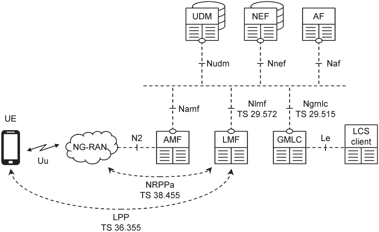
Figure 20.4 Representation of the location service architecture, using service‐based interfaces.
Source: Adapted from 3GPP TS 23.273.
In Release 15, the GMLC and LMF are part of the 5G core network. From Release 16, a network operator can reduce the location measurement latency by deploying those functions as part of the NG-RAN [25].
20.2.3 Enhancements to the Air Interface
From Release 16, the LMF can determine a mobile's location over the 5G New Radio using six different techniques [26]. The simplest is enhanced cell identity, which only uses measurements that the gNB is making anyway. These include the identities of the mobile's serving cells, the corresponding values of the uplink timing advance and the base stations' choices of spatially filtered beams.
The positioning accuracy can be improved by more sophisticated timing measurements. When using downlink time difference of arrival, the mobile measures the times at which downlink reference signals arrive from its serving cells and their nearest neighbours, and reports the time differences back to the network. The network can then determine the mobile's position by triangulation. Uplink time difference of arrival uses the base stations' measurements of the mobile's uplink reference signals, while measurements of the round‐trip time use both. At least in line‐of‐sight conditions, the resulting position estimates can be far more accurate than in LTE, because the larger bandwidth of 5G results in a shorter sample duration. However, the positioning accuracy degrades in a multipath environment, in which the measurements are corrupted by additional time delays.
The positioning accuracy can also be improved by a more sophisticated use of beamforming. When using downlink angle of departure, the mobile identifies the spatially filtered beams that arrive from its serving cells and their nearest neighbours, and reports the reference signal received power from each one. By interpolating between the individual beams, the network can determine the mobile's direction from each individual base station more accurately than before, and can combine the results to determine the mobile's location. Uplink angle of arrival is based on similar measurements by the base stations themselves.
When using these techniques, the mobile's measurements are made using a new downlink reference signal, which is known as the positioning reference signal (PRS). The base stations' measurements are made using the sounding reference signals from Release 15.
20.3 Integrated Access and Backhaul
20.3.1 Introduction
In the long term, the best way to increase the capacity of a 5G network will be through the use of millimetre wave communications. There are two reasons: each cell occupies a large amount of radio spectrum; and the individual cells are small, so their spectrum can be re‐used many times. However, the cost of deploying those cells could be large. One particular problem lies in the backhaul, where the cost of equipping each node with a fixed fibre‐optic connection or a dedicated point‐to‐point wireless link could be prohibitive.
One solution is integrated access and backhaul (IAB), in which the backhaul is implemented using the 5G New Radio itself. IAB is especially attractive for the case of millimetre wave communications, for two reasons. Firstly, the wide radio bandwidth implies that the air interface and backhaul can often use different radio frequencies without limiting the system capacity unduly. Secondly, even if their radio frequencies are the same, the network operator can minimize interference between them by the use of beamforming.
IAB is introduced into 5G as part of 3GPP Release 16 [27,28], with the work treated as a priority because of its potential impact on the roll‐out of 5G. The design is similar to that of relays in LTE, but those had a slightly different motivation, namely that of increasing the coverage of an LTE base station without the need to install a new small cell.
20.3.2 High‐level Architecture
The IAB architecture supports a number of topologies, two of which are shown in Figure 20.5. In these architectures, an IAB node is a base station with an integrated access and backhaul, which is controlled by a normal base station known as an IAB donor. The IAB node communicates with one or more mobiles by means of the 5G New Radio, and with the IAB donor by using the New Radio as a wireless backhaul. The simplest architecture uses a single‐hop backhaul, but a multi‐hop backhaul is a valuable alternative because of the short range of millimetre wave communications.

Figure 20.5 Example topologies for the integrated access and backhaul. (a) Single‐hop backhaul. (b) Multi‐hop backhaul.
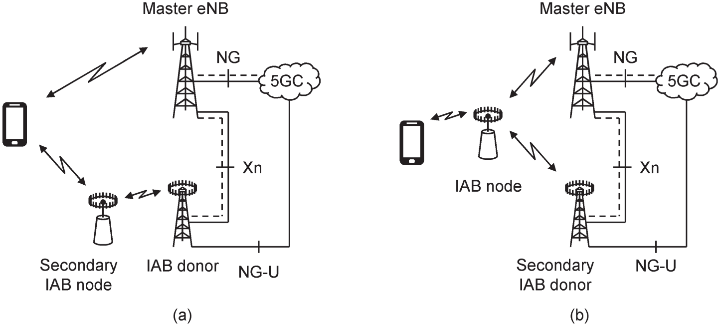
Figure 20.6 Example dual connectivity topologies for the integrated access and backhaul. (a) Mobile in dual connectivity with a master ng‐eNB and a secondary IAB node. (b) IAB node in dual connectivity with a master ng‐eNB and a secondary IAB donor.
Source: Adapted from 3GPP TR 38.874.
The architecture also supports multi‐radio dual connectivity for both the mobile and the IAB node. There is one restriction: any communications between an IAB node and a master eNB are limited to configuration and control of the IAB node itself, while wireless backhauling is carried out using the 5G New Radio alone. Figure 20.6 shows some examples that involve the 5G core network alone, but the mobile and/or IAB node can also be controlled by the evolved packet core.
IAB nodes are intended to be physically fixed. Even so, the network should be able to reconfigure the backhaul automatically, because individual millimetre wave links can be blocked by obstructions such as vehicles, seasonal foliage or new buildings. The resulting procedure is known as topology adaptation.
20.3.3 Architectural Details
Figure 20.7 shows some more detail of the architecture, for the case of the multi‐hop backhaul from Figure 20.5. The IAB donor contains gNB central and distributed units, in the usual way. Each IAB node contains a mobile termination (MT) for its upstream communications and a gNB distributed unit for its downstream communications, but no central unit. It therefore implements the air interface's physical layer, medium access control (MAC) and radio link control (RLC) protocols, but not the packet data convergence protocol (PDCP) or service data adaptation protocol (SDAP). Adding some more detail, an IAB node uses the MAC protocol to schedule its own downstream communications, and the RLC protocol to implement hop‐by‐hop re‐transmissions.

Figure 20.7 Integrated access and backhaul architecture.
Source: Adapted from 3GPP TR 38.874.
The IAB donor's central unit communicates with the IAB nodes' distributed units over a modified version of the F1 reference point, denoted F1*. That reference point transports information using the wireless backhaul instead of IP, so the new backhaul adaptation protocol (BAP) provides an interface between the overlying F1 protocols and the underlying RLC [29]. In the case of a multi‐hop backhaul, the adaptation layer also routes traffic and signalling messages between the IAB donor and the appropriate IAB node.
There are two possible relationships between the wireless backhaul and the air interface. In the case of an out‐of‐band backhaul, the air interface and wireless backhaul span different radio frequencies, so they can operate independently. In the case of an in‐band backhaul, their radio frequencies overlap or coincide, so the interference between them has to be minimized by means of time division multiplexing, frequency division multiplexing or beamforming.
20.4 Non‐terrestrial Networks
20.4.1 Introduction
A non‐terrestrial network (NTN) provides some or all of its coverage from platforms such as satellites or unmanned aircraft systems. 3GPP defined the requirements for NTNs as part of Release 15 [30,31], and investigated the system architecture and the resulting modifications to the 5G New Radio in Release 16 [32,33]. Two IEEE frequency bands have been of particular interest: S band transmissions around 2 GHz, and transmissions in the satellite Ka band in which the downlink and uplink are around 20 and 30 GHz respectively.
A satellite might be in low, medium or geostationary orbit, while the possible aircraft systems include balloons, airships and drones. As illustrated in Figure 20.8, the satellite or aircraft can be deployed transparently as part of the air interface or backhaul, or non‐transparently as a distributed unit or a gNB. There is also the possibility of relaying the transmission, for example by deploying an additional satellite or aircraft as an IAB node.
The main use of non-terrestrial networks is to improve the system's coverage in unserved or under‐served areas of the globe. For example, a network operator might offer coverage in remote land areas or over the oceans by deploying a satellite in the air interface or as a gNB, or in remote villages by deploying a satellite in the backhaul. NTNs can also improve the system's reliability and resilience for applications such as public safety, and can address market sectors such as shipping and aircraft that terrestrial networks are unable to handle. Furthermore, integrating the non‐terrestrial component into 5G offers the extra benefit of seamless coverage and roaming. For example, a shipping company might track the delivery of containers over the ocean using satellite communications, and then follow their subsequent route on land using the cellular network [34].
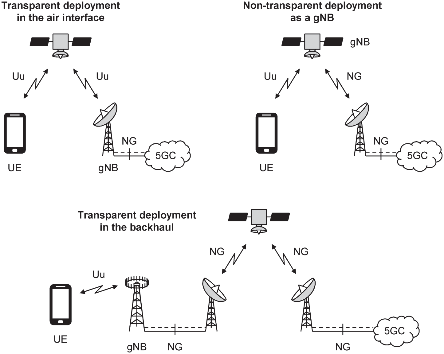
Figure 20.8 Deployment options for a non‐terrestrial network.
20.4.2 Design Challenges
NTNs have a number of design challenges [35], and the specifications are expected to form part of Release 17. The first problem is the large propagation delay. A geostationary satellite is at an altitude of 35 786 km above sea level. If the satellite is deployed transparently as part of the air interface, then the distance between the mobile and the base station is at least twice that amount, 71 572 km, which is over 200 times greater than the distance of 300 km that 5G was designed to handle. In turn, the one‐way propagation delay is at least 238 ms, or even larger if the satellite is not directly overhead. As partial compensation, the mobiles are each at similar distances from the satellite so the differential delay between them is much smaller, no more than about 16 ms.
There are several impacts. Firstly, the re‐transmission procedures have to be modified to handle the full propagation delay, both in the physical layer and in the RLC protocol. Secondly, the guard period in TDD mode has to be increased to handle the full propagation delay, which makes TDD mode unsuitable for the geostationary case. Thirdly, the air interface's control loops operate more slowly, so they are unable to compensate for issues such as fading. Finally, the timing advance procedure has to be modified to handle the differential delay.
The second problem is the platform's speed. A satellite in low earth orbit travels at about 28 000 km h−1, which is over 50 times greater than the speed of 500 km h−1 that 5G was designed to handle. The resulting Doppler shift can be as great as 50 kHz at a carrier frequency of 2 GHz, or 500 kHz at a carrier frequency of 20 GHz, and can change very quickly as the satellite passes overhead. These Doppler shifts are too large for the Release 15 acquisition procedures to handle, and also lead to inter‐carrier interference.
A third problem is mobility management. The beams of a satellite in low earth orbit move quickly over the ground, which requires fast, reliable handovers for mobiles in RRC_CONNECTED, and careful management of tracking areas for mobiles in RRC_IDLE. If the tracking areas are fixed with respect to the satellite's beams, then they move over the ground, and the number of registration updates is large. If they are fixed with respect to the ground, then the mobile has to discover its tracking area from a separate location service, and the network has to maintain a dynamically changing conversion between tracking areas and satellite beams. 3GPP has adopted the second approach.
20.5 Massive Machine‐type Communications
20.5.1 Introduction
When writing the specifications for the 5G New Radio, 3GPP focussed on the use cases for enhanced mobile broadband and for ultra‐reliable low‐latency communication. However, the New Radio does not support all of the stated requirements for massive machine‐type communications, notably those for enhanced coverage and a long battery life.
Instead, 3GPP decided to support these applications through the earlier air interface technologies of enhanced machine‐type communications (eMTC) and the narrowband internet of things (NB‐IoT) [36-38]. From Release 16, a machine‐type device can access the 5G core network by means of eMTC and NB‐IoT. The resulting system addresses all the requirements for machine‐type communications, while allowing machine‐type devices to benefit from the new capabilities of the 5G core. It also supports mobility between the 5G core network and the evolved packet core to handle situations where the mobile moves away from a base station that supports the NG reference point, and reselects or hands over to a base station that only supports S1.
20.5.2 Enhancements to the 5G Core Network
Release 16's support for machine‐type communications involves several enhancements to the 5G core network, which replicate features that were introduced to the evolved packet core under the name of the cellular internet of things (CIoT). The first helps the delivery of small data packets, while minimizing the signalling overhead and maximizing the mobile's battery life. From Release 16, the system can maintain a mobile's access stratum parameters, for example its access stratum security keys, while the mobile is idle. That replicates the mobile's behaviour in the 5G state of RRC_INACTIVE, and allows it to run the service request procedure and re‐activate its radio bearers with minimal signalling overhead.
In another technique, a mobile can send and receive small data packets by embedding them into the 5G session management messages that it exchanges with the session management function (SMF). From idle mode, the mobile can do so after running the procedure of RRC connection setup, but without any need to run the service request procedure or to re‐activate its data radio bearers. The SMF can exchange those packets with an external server in two ways: either on the user plane by way of the user plane function (UPF), or on the control plane by way of the NEF.
A second set of enhancements reduces the mobile's power consumption. Release 15 already allowed a mobile to request a mode known as mobile‐initiated connection only (MICO), in which it does not listen for paging messages in the state of CM‐IDLE, and only contacts the network to carry out a periodic registration update or some other mobile‐initiated transmission. Release 16 adds an active time. After a transition from CM‐CONNECTED to CM‐IDLE, a MICO‐enabled mobile stays in the normal idle mode for a time that is limited by the interval between its periodic registration updates, and only then enters MICO mode.
Another power‐saving technique is extended discontinuous reception (eDRX). This increases the mobile's discontinuous reception cycle length to a maximum of 10 485.76 seconds, which is nearly 3 hours. For both of these power‐saving techniques, the SMF, NEF and UPF can be enhanced to support extended buffering, in which they agree to buffer incoming downlink data for longer than they usually do.
20.5.3 NR Light
A study is taking place as part of Release 17 into a modified version of the 5G New Radio, which is provisionally known as NR Light [39]. Once implemented, NR Light will offer a solution for machine‐type devices which is fully integrated into the 5G New Radio, but which addresses a slightly different set of performance requirements from before. In particular, the data rate, reliability and latency of NR Light are likely to be better than those of eMTC and NB‐IoT, but the coverage is likely to be worse. Applications include higher‐end machine‐type devices such as security cameras and wearable devices, which are not so well addressed by the earlier technologies.
20.6 Other New Features and Studies
20.6.1 Enhancements to the Service‐based Architecture
We introduced the Release 15 procedures for network function registration and discovery in Chapter 2. In Release 15, a network function consumer explicitly discovers individual instances of a network function producer by sending a request to the network repository function (NRF). It then selects a single producer from the list that the NRF returns and contacts the producer directly by means of its service‐based interface.
Release 16 builds upon that architecture by introducing the service communication proxy (SCP) [40,41]. The SCP acts as an application‐layer router for HTTP/2 signalling on the core network's service‐based interfaces, by receiving HTTP/2 requests from a network function consumer, selecting a suitable producer and forwarding the signalling on. As part of that task, the SCP carries out network function service discovery implicitly, without the need for the consumer to contact the NRF at all. It also carries out centralized load balancing by selecting a suitable producer using its overall knowledge of the load within the network.
20.6.2 Support for Vertical and LAN Services
Release 16 extends 5G's support for ultra-reliable low-latency communication to cyber‐physical control applications, in other words industrial control systems containing a mix of physical components such as sensors and actuators, and computational components such as a centralized control system [42-45].
Two enhancements are especially important [46]. The first is time‐sensitive networking. In some control systems, the sensors and actuators have to be time‐synchronized, with a tolerance that can be as small as one microsecond. Release 16 handles this issue by distributing an external timing signal over the 5G network, treating the 5G system as a time‐aware system in accordance with IEEE specification 802.1AS [47].
The second is support for a non‐public network (NPN), in other words part or all of a 5G network that is private to an industrial client. A NPN can be implemented in three ways: as a stand‐alone network, identified by combining the public land mobile network identity (PLMN‐ID) with a separate network identifier; as a slice of a public network; or by reserving cells in a public network for private use by assigning them to a closed access group.
20.6.3 Self‐optimizing Networks
LTE supports a number of techniques for automatic configuration and optimization of the radio access network, under the name of self‐optimizing or self‐organizing networks (SONs). 5G replicated two of these techniques in Release 15. The first is the configuration of automatic neighbour relations and the Xn interface. If a node receives a measurement report about a neighbouring physical cell identity that it wasn't previously aware of, then it can ask the mobile to read system information block 1 from the neighbouring cell, and to return the corresponding New Radio cell identity, tracking area code and PLMN list [48]. It can then initiate an NG‐based handover. It can also ask the AMF to retrieve an IP address from the neighbouring node, and can use that IP address to establish signalling communications with the neighbour over Xn [49]. The second technique is energy saving, which allows a network to switch its small cells on and off automatically in response to changes in the network load, while maintaining the macrocells that are required for coverage purposes [50].
Other features are replicated in Release 16 [51,52]. Using automatic PCI configuration, a distributed unit can assign physical cell identities to its cells without intervention from the network operator, avoiding identities that are being used by other cells nearby by means of a downlink receiver. Mobility robustness optimization allows the radio access network to detect handover failures that arise due to poor choices of measurement reporting thresholds, and to correct them. Mobility load balancing allows nearby base stations to exchange information about their load levels by means of Xn signalling, so that a congested base station can hand over some of its mobiles to less congested neighbours. Finally, RACH optimization allows nearby cells to exchange information about the parameters used for the random access channel, so as to minimize the interference between their random access transmissions.
20.6.4 Use of Unlicensed Spectrum
5G networks mainly use licensed spectrum, in which the network is centrally planned for low interference and seamless coverage, which in turn delivers high data rates and high reliability. However, the capacity of a 5G network can also be increased by the use of unlicensed spectrum.
LTE was enhanced to operate in unlicensed spectrum from Release 13, and 5G is enhanced in a similar way as part of Release 16 [53]. An important aspect is the need to avoid causing interference to WiFi receivers that are operating in the same frequency band. That is implemented by adopting a WiFi mechanism known as listen before talk (LBT), in which a 3GPP device pauses before transmission to ensure that no other devices are attempting to do so.
20.6.5 Reduction of Cross‐link Interference
In TDD mode, there is a risk of interference from the downlink transmitter of one base station to the uplink receiver of another. Usually, that interference is only a problem over short distances, and can be controlled by co‐ordinating the TDD configurations of base stations that are nearby. Sometimes, however, it can also be a problem over longer distances, as much as 300 km or so, due to scattering and reflection from the upper atmosphere. It is then known as cross‐link interference (CLI).
Release 16 introduces measures to detect cross-link interference and to reduce it [54-56]. If a victim TDD cell detects excess levels of uplink interference that are consistent with the expected behaviour of CLI, then it can start transmitting a remote interference management reference signal (RIM‐RS) on the downlink. In the presence of channel reciprocity, the aggressor detects the reference signal, and takes action by adjusting its TDD configuration. It can also send an indication back to the victim, either by a reference signal of its own or by signalling messages over the backhaul, to help the victim establish whether the aggressor's actions have been enough.
20.6.6 Further Enhancements to the 5G New Radio
Release 16 includes a number of other enhancements to the 5G New Radio. There are several measures to reduce the mobile's power consumption, for example by dynamically reducing the number of physical downlink control channel (PDCCH) monitoring occasions if the data rate is low [57]. The usage of multiple antennas is enhanced, to increase the system capacity, and to improve its robustness when using multiple spatially filtered beams [58]. The handover procedure is also enhanced, to improve the procedure's reliability, and to reduce the interruption time for mobiles with a dual protocol stack that can simultaneously communicate with the source and target nodes [59,60]. Another new feature is the introduction of a random access procedure that contains only two steps rather than four, with a view to reducing the procedure's latency [61].
Other proposed enhancements include the operation of 5G in new frequency ranges. 3GPP studied the ranges from 7 to 24 GHz [62] and beyond 52.6 GHz [63] as part of Release 16, and plans to implement the range from 52.6 to 71 GHz in Release 17 [64]. Issues being addressed include national regulatory requirements, suitable architectures for the base station and mobile, the precise dividing lines between the different frequency ranges, and the additional problems at high radio frequencies due to atmospheric absorption and phase noise. Another study concerns non‐orthogonal multiple access (NOMA) [65]. 3GPP investigated several other multiple access schemes for 5G as part of Release 14, but abandoned them in favour of the continued use of OFDMA. However, those other schemes can offer a number of benefits, for example signalling and latency reductions, by skipping OFDMA's explicit allocation of mobiles to subcarriers.
References
- 1 3GPP TR 22.885 (2015) Study on LTE support for vehicle to everything (V2X) services (Release 14), December 2015.
- 2 3GPP TS 22.185 (2018) Service requirements for V2X services; Stage 1 (Release 15), June 2018.
- 3 3GPP TR 22.886 (2018) Study on enhancement of 3GPP support for 5G V2X services (Release 16), December 2018.
- 4 3GPP TS 22.186 (2019) Enhancement of 3GPP support for V2X scenarios; Stage 1 (Release 16), June 2019.
- 5 SAE International J3016_201806 (2018) Taxonomy and definitions for terms related to driving automation systems for on‐road motor vehicles, June 2018.
- 6 3GPP TR 23.785 (2016) Study on architecture enhancements for LTE support of V2X services (Release 14), September 2016.
- 7 3GPP TS 23.285 (2019) Architecture enhancements for V2X services (Release 16), December 2019.
- 8 3GPP TR 23.786 (2019) Study on architecture enhancements for the evolved packet system (EPS) and the 5G system (5GS) to support advanced V2X services (Release 16), June 2019.
- 9 3GPP TS 23.287 (2019) Architecture enhancements for 5G system (5GS) to support vehicle‐to‐everything (V2X) services (Release 16), December 2019.
- 10 3GPP TR 23.795 (2018) Study on application layer support for V2X services (Release 16), December 2018.
- 11 3GPP TS 23.286 (2019) Application layer support for vehicle‐to‐everything (V2X) services; Functional architecture and information flows (Release 16), December 2019.
- 12 3GPP TR 38.885 (2019) NR; Study on NR vehicle‐to‐everything (V2X) (Release 16), March 2019.
- 13 3GPP TR 37.985 (2019) Overall description of radio access network (RAN) aspects for vehicle‐to‐everything (V2X) based on LTE and NR (Release 16), November 2019.
- 14 3GPP TR 38.886 (2019) V2X Services based on NR; User equipment (UE) radio transmission and reception (Release 16), February 2020.
- 15 3GPP TR 38.855 (2019) Study on NR positioning support (Release 16), March 2019, Section 4.
- 16 3GPP TR 22.872 (2018) Study on positioning use cases; Stage 1 (Release 16), September 2018.
- 17 US Department of Defense (2008) GPS Standard Positioning Service (SPS) Performance Standard, 4th ed., US Department of Defense, September 2008.
- 18 3GPP TR 23.731 (2018) Study on enhancement to the 5GC location services (Release 16), December 2018.
- 19 3GPP TS 23.273 (2019) 5G system (5GS) location services (LCS); Stage 2 (Release 16), December 2019.
- 20 Open Mobile Alliance (2011) Mobile Location Protocol Version 3.1. http://www.openmobilealliance.org/release/MLP/V3_1-20110920-A/OMA-LIF-MLP-V3_1-20110920-A.pdf (accessed 18 January 2020).
- 21 3GPP TS 29.515 (2019) 5G system; Gateway mobile location services; Stage 3 (Release 16), December 2019.
- 22 3GPP TS 29.572 (2019) 5G system; Location management services; Stage 3 (Release 16), December 2019.
- 23 3GPP TS 38.455 (2019) NG‐RAN; NR positioning protocol A (NRPPa) (Release 15), January 2019.
- 24 3GPP TS 37.355 (2019) LTE positioning protocol (LPP) (Release 15), December 2019.
- 25 3GPP TR 38.856 (2019) Study on local NR positioning in NG‐RAN (Release 16), December 2019.
- 26 3GPP TR 38.855 (2019) Study on NR positioning support (Release 16), March 2019.
- 27 3GPP TR 38.874 (2018) NR; Study on integrated access and backhaul (Release 16), December 2018.
- 28 3GPP TS 38.174 (2019) NR; Integrated access and backhaul radio transmission and reception (Release 16), September 2019.
- 29 3GPP TS 38.340 (2019) NR; Backhaul Adaptation Protocol (BAP) specification (Release 16), November 2019.
- 30 3GPP TR 22.822 (2018) Study on using satellite access in 5G; Stage 1 (Release 16), June 2018.
- 31 3GPP TR 38.811 (2019) Study on New Radio (NR) to support non‐terrestrial networks (Release 15), September 2019.
- 32 3GPP TR 23.737 (2019) Study on architecture aspects for using satellite access in 5G (Release 17), December 2019.
- 33 3GPP TR 38.821 (2019) Solutions for NR to support non‐terrestrial networks (NTN) (Release 16), January 2020.
- 34 3GPP TR 22.822 (2018) Study on using satellite access in 5G; Stage 1 (Release 16), June 2018, Section 5.1.
- 35 3GPP TR 38.811 (2019) Study on New Radio (NR) to support non‐terrestrial networks (Release 15), September 2019, Sections 5, 7.
- 36 3GPP RP‐180581 (2018) Interim conclusions on IoT for Rel‐16, March 2018.
- 37 3GPP TR 23.724 (2019) Study on cellular internet of things (CIoT) support and evolution for the 5G system (5GS) (Release 16), June 2019.
- 38 3GPP TS 23.501 (2019) System architecture for the 5G system (5GS); Stage 2 (Release 16), December 2019, Section 5.31.
- 39 3GPP RP‐193238 (2019) New SID on support of reduced capability NR devices, December 2019.
- 40 3GPP TR 23.742 (2018) Study on enhancements to the service‐based architecture (Release 16), December 2018.
- 41 3GPP TS 23.501 (2019) System architecture for the 5G system (5GS); Stage 2 (Release 16), December 2019, Sections 6.2.19, 6.3.1, 7.1.1, E, G.
- 42 3GPP TR 22.804 (2018) Study on communication for automation in vertical domains (Release 16), December 2018.
- 43 3GPP TR 22.821 (2018) Feasibility study on LAN support in 5G (Release 16), June 2018.
- 44 3GPP TS 22.104 (2019) Service requirements for cyber‐physical control applications in vertical domains; Stage 1 (Release 16), December 2019.
- 45 3GPP TR 23.734 (2019) Study on enhancement of 5G system (5GS) for vertical and local area network (LAN) services (Release 16), June 2019.
- 46 3GPP TS 23.501 (2019) System architecture for the 5G system (5GS); Stage 2 (Release 16), December 2019, Sections 4.4.8, 5.27, 5.28, 5.30.
- 47 IEEE P802.1AS (2019) IEEE draft standard for local and metropolitan area networks – Timing and synchronization for time‐sensitive applications, Draft 8.3, October 2019.
- 48 3GPP TS 38.331 (2019) NR; Radio resource control (RRC) protocol specification (Release 15), December 2019, Section 6.3.2 (CGI‐InfoEUTRA, CGI‐InfoNR).
- 49 3GPP TS 38.423 (2019) NG‐RAN; Xn application protocol (XnAP) (Release 15), December 2019, Section 8.4.1.
- 50 3GPP TS 38.423 (2019) NG‐RAN; Xn application protocol (XnAP) (Release 15), December 2019, Sections 8.4.2, 8.4.3.
- 51 3GPP TR 28.861 (2019) Telecommunication management; Study on the self‐organizing networks (SON) for 5G networks (Release 16), December 2019.
- 52 3GPP TR 37.816 (2019) Study on RAN‐centric data collection and utilization for LTE and NR (Release 16), July 2019.
- 53 3GPP TR 38.889 (2018) Study on NR‐based access to unlicensed spectrum (Release 16), December 2018.
- 54 3GPP TR 38.828 (2019) Cross link interference (CLI) handling and remote interference management (RIM) for NR (Release 16), September 2019.
- 55 3GPP TR 38.866 (2019) Study on remote interference management for NR (Release 16), March 2019.
- 56 3GPP TS 38.300 (2019) NR; NR and NG‐RAN overall description; Stage 2 (Release 16), December 2019, Section 17.
- 57 3GPP TR 38.840 (2019) NR; Study on user equipment (UE) power saving in NR (Release 16), June 2019.
- 58 3GPP RP‐192271 (2019) Revised WID: Enhancements on MIMO for NR, September 2019.
- 59 3GPP RP‐192534 (2019) New WID: NR mobility enhancements, December 2019.
- 60 3GPP TS 38.213 (2019) NR; Physical layer procedures for control (Release 16), December 2019, Section 15.
- 61 3GPP RP‐190711 (2019) Revised work item proposal: 2‐step RACH for NR, March 2019.
- 62 3GPP TR 38.820 (2019) NR; 7–24 GHz frequency range (Release 16), December 2019.
- 63 3GPP TR 38.807 (2019) Study on requirements for NR beyond 52.6 GHz (Release 16), December 2019.
- 64 3GPP RP‐193229 (2019) Extending current NR operation to 71GHz, December 2019.
- 65 3GPP TR 38.812 (2018) Study on non‐orthogonal multiple access (NOMA) for NR (Release 16), December 2018.