
13
Registration Procedures
We will now move on to a set of seven chapters that cover the end‐to‐end operation of 5G. Throughout these chapters, the main focus will be on architectural options that involve the 5G core network, although we will restrict some aspects to architectures that require a master gNB. To keep things simple, we will mainly assume the use of an integrated gNB, but we will discuss what happens if the gNB is split into central and distributed units as part of Chapter 18. We will also address inter‐operation with the evolved packet core in Chapter 19.
The main specification for these discussions is TS 23.502 [1], which covers the signalling procedures within the 5G core. The equivalent procedures in the radio access network (RAN) form part of TS 38.300 [2], while full details of the resulting signalling are in the corresponding stage 3 specifications, which were laid out in Chapters 2 and 3. The use of service‐based interfaces and HTTP/2 makes the core network's signalling more intricate than in previous generations, and readers may wish to review the discussion of HTTP/2 in Chapter 2 before proceeding.
In this chapter, we will address the procedures by which the mobile registers with the 5G core network when it switches on. In doing so, we will cover the procedures for network and cell selection, for the establishment of a radio resource control (RRC) signalling connection with the RAN and for registration itself. As part of the discussion, we will address how a mobile chooses between a 4G cell controlled by an eNB and a 5G cell controlled by a gNB, and how it chooses between the evolved packet core and the 5G core. As well as the specifications listed in the previous paragraph, two others are particularly relevant for this chapter, namely the specifications for idle mode procedures in the non‐access stratum (NAS), TS 23.122 [3], and the access stratum (AS), TS 38.304 [4].
13.1 Power‐on Sequence
Figure 13.1 summarizes the procedure by which a mobile establishes communications with a master gNB and registers with the 5G core, under architectural option 2. To begin the procedure, the mobile selects a public land mobile network (PLMN) that it will register with, and a 5G cell that belongs to the PLMN. In doing so, the mobile is said to camp on the cell.

Figure 13.1 Overview of the power‐on procedures in architectural options 2 and 4.
Using the selected cell, the mobile contacts the corresponding gNB using the random access procedure from Chapter 9. It then initiates a procedure known as RRC connection establishment, in which it establishes a signalling connection with the selected gNB and moves to the state of RRC_CONNECTED. As part of that procedure, the gNB configures the mobile with a set of parameters for communication over the air interface, including a set of uplink and downlink bandwidth parts, and configuration parameters for signalling radio bearer 1 (SRB 1).
Using the selected gNB, the mobile then initiates the registration procedure. During that procedure, the mobile registers with an access and mobility management function (AMF) in the 5G core network, and moves to the states of RM‐REGISTERED and CM‐CONNECTED. The mobile also receives a set of configuration parameters for SRB 2.
Subsequently, the mobile can establish connectivity with an external data network, using signalling procedures that we will cover in Chapter 15. If it does not do so, or after any later lapse in data communications, then the network can transfer the mobile to the states of CM‐IDLE and RRC_IDLE in the manner described in Chapter 16.
As an alternative to this procedure, the mobile might select a 4G cell and establish a signalling connection with the corresponding eNB. Depending on how that cell is configured, the mobile can then register either with the 5G core network using the procedure introduced above (architectural option 5) or with the evolved packet core using the attach procedure from LTE (option 1).
13.2 Network and Cell Selection
13.2.1 Network Selection
The network selection procedure is much the same as in previous generations [5]. After switching on, the mobile reads several parameters from the Universal Subscriber Identity Module (USIM) [6]. These include the tracking area in which the mobile was last registered, from which it extracts the identity of the corresponding network, known as the registered PLMN.
The mobile now searches for cells that belong to the registered PLMN, using all of the radio access technologies that it supports. The search begins on any radio frequencies that the mobile stored when it was last switched on. If the mobile does not find the registered PLMN on any of those radio frequencies, then it scans all the frequency bands that it supports, using all of its access technologies.
In the case of 5G cells, the mobile runs the acquisition procedure from Chapter 8 and identifies the strongest cell in each frequency band, ignoring cells which are barred or which are not transmitting system information block 1 (SIB 1) [7]. It then reads the PLMN identity list from SIB 1. There is a similar procedure for 4G cells, except that they can advertise two independent lists of network identities: one list of 5G core networks that can be reached over the NG reference point, and one list of evolved packet core networks that can be reached over S1.
If the mobile cannot find the registered PLMN, then it moves to one of two modes for network selection, with the choice configured by the user. In automatic mode, the mobile first looks through a prioritized list of network identities that it should treat as home networks, and then tries prioritized lists of network identities that have been defined by the user and by the operator. Each of those networks can be associated with a prioritized list of radio access network technologies, which sets up a priority order between the evolved UMTS terrestrial radio access network (E‐UTRAN) and the next‐generation radio access network (NG‐RAN), but does not distinguish between 4G and 5G cells within the NG‐RAN. If the mobile cannot find any of those networks, then it selects any network whose received signal power is sufficiently high or, failing that, any network at all.
In the last two cases, the selected network might not have a roaming agreement with the home network operator. In that situation, the registration procedure will fail. If that happens for every network, then the mobile enters a limited service state, in which it can only make emergency calls, or receive warnings from the earthquake and tsunami warning system and the commercial mobile alert service.
In manual mode, the mobile presents the user with the networks that it has found, with the networks listed in the same priority order as in automatic mode. The network is then selected by the user.
13.2.2 Cell Selection
During the cell selection procedure, the mobile chooses a suitable cell that belongs to the selected network and to the selected radio access network technology. A suitable cell is one that satisfies several criteria. In the case of a 5G cell, the most important are two criteria on the strength of the received signal [8,9]. Firstly, the received signal power has to satisfy the following condition:
where Qrxlevmeas is the synchronization signal reference signal received power (SS‐RSRP), which is the average power per resource element that the mobile receives on the cell's secondary synchronization signal (SSS); and Qrxlevmin is the minimum value of SS‐RSRP, which the base station advertises in SIB 1. Thus, to a first approximation, the equation simply states that the received signal power should be sufficiently high.
There are several refinements. Firstly, if the cell is using multiple beams, then the mobile will measure a different value of SS‐RSRP on each beam. During cell selection, the mobile can convert those into a cell‐specific value in any way that it pleases, for example by choosing the largest. Secondly, if the cell has a supplementary uplink (SUL), then it can advertise a second, lower value of Qrxlevmin, which the mobile chooses if it supports the SUL. That allows the mobile to select a weaker cell than it usually would, safe in the knowledge that it can still reach the cell by means of the SUL. Thirdly, Qrxlevminoffset and Qoffset, temp are both zero during initial cell selection: they are respectively used in the procedure for network reselection (Section 17.3.2), and after repeated failures to establish communications with the cell.
In basic deployments, the final parameter is calculated as follows:
In this equation, PPowerClass is the mobile's maximum transmit power. The 5G specifications define different power classes for different types of mobile, the default being power class 3 [10,11]. For those mobiles, the transmit power is limited to 23 dB relative to 1 mW (dBm), in other words about 200 mW, while the equivalent isotropic radiated power is limited to 43 dBm in frequency range 2 to account for the transmit array gain. PEMAX1 is the maximum uplink power that is allowed within the cell, which the base station advertises as part of SIB 1. By combining these quantities, Pcompensation makes the mobile less likely to select the cell if its transmit power is lower than the maximum value that the base station is expecting, and reduces the risk of uplink coverage problems. In more complex deployments, the base station can also enforce an additional maximum power reduction, which limits the mobiles' emissions into adjacent frequency bands.
In addition, the received signal quality has to satisfy the following condition:
where Qqualmeas is the synchronization signal reference signal received quality (SS‐RSRQ), which equals the value of SS‐RSRP divided by the average power per resource element that the mobile receives from all sources, including signal, interference and noise; Qqualmin is a minimum value that the base station advertises in SIB 1, with the same value used for the normal and supplementary uplink; and Qqualminoffset and Qoffset, temp are both zero during initial cell selection, as before. This criterion prevents a mobile from selecting a cell with a strong received signal, if the cell is subject to high levels of interference.
Furthermore, a suitable cell must not be barred or reserved for operator use, and must not lie in any forbidden tracking areas that are listed in SIB 1. The criteria for selection of a suitable 4G cell are similar [12].
13.3 RRC Connection Establishment
13.3.1 RRC Connection Establishment with a gNB
If the mobile selected a 5G cell, then it contacts the corresponding gNB using the random access procedure from Chapter 9. During initial registration, message 3 of that procedure is an RRC Setup Request. That initiates the procedure of RRC connection establishment, which is illustrated in Figure 13.2 [13].

Figure 13.2 RRC connection establishment procedure.
Source: Adapted from 3GPP TS 38.331.
As part of its RRC Setup Request (step 1), the mobile identifies itself using the unique identity that we introduced as part of the random access procedure. It also states the establishment cause, in other words its reason for sending the request. In this example, the cause is mobile‐originated signalling, while other causes include mobile‐originated data, an emergency call and a response to mobile‐terminated paging.
The base station receives the message, takes on the role of the mobile's master gNB and replies with the message RRC Setup (2). That message configures the mobile's master cell group, perhaps taking the mobile into an immediate state of carrier aggregation. It also provides each cell with a set of downlink bandwidth parts, a set of uplink bandwidth parts and a set of parameters for each one. Other parameters apply to each individual cell, for example the TDD configuration, and to the master cell group as a whole, for example the configuration of the medium access control (MAC) protocol. The message also configures SRB 1 and its associated radio link control (RLC) and packet data convergence protocol (PDCP) entities. The mobile applies the requested configuration, and moves into the state of RRC_CONNECTED.
Having done so, the mobile acknowledges its configuration by sending the message RRC Setup Complete (3). That message includes a 5G mobility management (5GMM) message that the base station should deliver to the core network, in this case a Registration Request. It also states the selected network identity, the requested network slices, and the globally unique identity of the AMF with which the mobile was previously registered. The base station uses these information elements for the procedure of AMF selection, which is described further in this chapter.
13.3.2 Initial UE Message
The gNB now chooses a suitable AMF for the mobile [14]. If it is connected to the mobile's previous AMF, then it chooses that one. Otherwise, the base station chooses an AMF from the ones to which it is connected, using information such as the capacity of each one, the network and slices that the mobile requested, and the mobile's previous AMF set. If the base station cannot identify a suitable AMF, then it chooses any AMF that is itself configured for AMF selection.
The gNB then forwards the mobile's registration request to the AMF by embedding it into an NG application protocol (NG‐AP) Initial UE Message, as shown in Figure 13.3 [15]. That message requests the establishment of an NG signalling connection for the mobile and supplies a 32‐bit field that the base station will use to identify the mobile over NG. The message also includes the selected network identity, the tracking area code of the selected cell and the establishment cause from earlier. The AMF extracts the registration request and continues with the registration procedure in Section 13.4.

Figure 13.3 Initial UE message procedure.
Source: Adapted from 3GPP TS 38.413.
13.3.3 RRC Connection Establishment with an eNB
If the mobile selected a 4G cell, then it contacts the corresponding eNB using the random access and RRC connection establishment procedures from LTE [16]. The base station then takes on the role of the mobile's master eNB.
In the LTE message RRC Connection Setup Complete, the mobile states whether the selected network is one of the 5G core networks that the base station advertised in SIB 1, or one of the evolved packet cores. In the first case (option 5), the eNB forwards the message to an AMF in the manner described in Section 13.4, and the mobile continues with the 5G registration procedure below. In the second case (option 1), the eNB forwards the message to a mobility management entity in the evolved packet core, and the mobile continues with the attach procedure from LTE [17].
13.4 Registration Procedure
13.4.1 Registration Without AMF Change
During the registration procedure, the mobile registers itself with a serving AMF in the 5G core network, through a set of network slices that is known as the allowed network slice selection assistance information (NSSAI). Figure 13.4 shows the simplest version of the procedure, in which the mobile is not roaming, and the serving AMF is unchanged from the mobile's previous registration [18,19]. Solid lines are for mandatory messages, while dashed lines are for ones that are optional or conditional. The numbering scheme is the same as in the stage 2 specification, a convention that we will apply throughout the chapters that follow. (Several messages are omitted: some of them are unusual, but others will appear in more complex versions of the procedure.)

Figure 13.4 Registration procedure if the AMF is unchanged.
Source: Adapted from 3GPP TS 23.502.
To begin the procedure, the mobile composes a 5GMM Registration Request. In the message, the mobile requests an initial registration, and identifies itself using the 5G globally unique temporary identity (5G-GUTI) from its previous registration, if available, or its subscription concealed identifier (SUCI) otherwise. It also states its requested NSSAI, in other words the network slices with which it would like to register.
As part of the message, the mobile includes a NAS key set identifier, which identifies the security keys that it was using when it was last switched on. The mobile uses those keys to secure the message by means of integrity protection, and to cipher most of its information elements [20]. However, it leaves in plain text any information elements that are required for AMF selection and security establishment, for example its temporary identity and the NAS key set identifier itself.
The mobile is unable to send the message right away, so it triggers the RRC connection establishment procedure from earlier. The message is delivered to the AMF as part of the earlier messages RRC Connection Setup Complete and Initial UE Message (steps 1–3).
In this example, the AMF recognizes the temporary identity from the mobile's previous registration. That allows it to retrieve the information it had previously stored about the mobile, known as the UE context, which includes the mobile's permanent identities and radio access capabilities, and the previous values of its security keys and allowed NSSAI. (If the UE context is missing, perhaps due to a database failure in the network, then the AMF retrieves the subscription concealed identifier from the mobile itself.)
Using the retrieved security keys, the AMF checks the integrity of the mobile's message. It can now authenticate the mobile, using a security procedure that we will cover in Chapter 14 (9a). The procedure is mandatory if the integrity check failed and optional otherwise, but is generally called because it triggers an update of the mobile's NAS security keys (9b). The AMF also checks that the requested NSSAI is consistent with the allowed NSSAI.
The AMF contacts the mobile's master node by means of an NG‐AP Initial Context Setup Request to establish an NG signalling connection for the mobile (9c). The message includes the mobile's radio access capabilities and a security key that is denoted KgNB. The message also includes core network assistance information, which helps the master node during a later transition to RRC_INACTIVE or RRC_IDLE.
Using the security key, the master node initializes access stratum security for the mobile. It then contacts the mobile using a general‐purpose message that reconfigures the mobile's air interface, which in this case is used to establish SRB 2. In the case of a master gNB the message is a 5G RRC Reconfiguration, while a master ng‐eNB uses the equivalent 4G message RRC Connection Reconfiguration. (The master node can also retrieve the mobile's radio access capabilities if it did not receive them from the AMF.) Having done so, the master node sends an acknowledgement to the AMF (9d).
Optionally, the AMF can send the mobile's permanent equipment identity to the 5G equipment identity register, to check that the mobile equipment has not been stolen (12). However, network operators do not often implement the EIR, so this step is often omitted.
We have now reached the first procedure on a service‐based interface. The AMF selects a policy control function (PCF) and contacts it using the Create operation from the PCF's AMPolicyControl service (16). That operation requests an access and mobility policy that will constrain how the AMF controls the mobile, and simultaneously asks for notifications if the policy is updated. The operation is implemented as an HTTP POST to the uniform resource identifier (URI)
../policies
, in the manner described in Chapter 2. The PCF responds with an HTTP 201 Created, and includes a child URI for the new policy as an HTTP header. It also supplies two fields in the form of JavaScript Object Notation (JSON) data, namely a service area restriction containing a list of allowed tracking areas for the mobile, and a RAT/frequency selection priority (RFSP) that influences the mobile's choice of radio access technology in RRC_IDLE.
Using a similar HTTP request, the AMF also retrieves a UE policy that will constrain the mobile's internal behaviour (21b). The PCF's reply includes a UE route selection policy, which contains application‐specific rules that tell the mobile how to manage its connections with external data networks. It also includes an access network discovery and selection policy, which helps the mobile use non‐3GPP access networks such as WiFi [21].
The AMF can now accept the mobile's registration request (21). The message includes a new temporary identity, the mobile's allowed NSSAI and tracking area list, a timer for periodic registration updates, and a list of networks that the mobile can assume are equivalent to the current one. On receiving the mobile's acknowledgement of its new temporary identity (22), the AMF can forward any UE policy transparently to the mobile [22].
13.4.2 Registration with a New AMF
If the mobile has moved since its previous registration, then the AMF may have to change. The resulting procedure is more complex, and is shown in Figure 13.5.
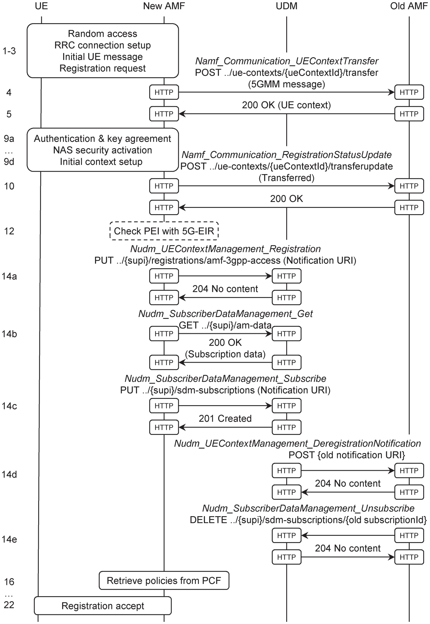
Figure 13.5 Registration procedure if the new AMF is different from the old one.
Source: Adapted from 3GPP TS 23.502.
The mobile sends a Registration Request in the same way as before, but this time the master node forwards the message to a new AMF, which does not recognize the mobile's temporary identity (steps 1–3). If the network has deployed an unstructured data storage function (UDSF), then the AMF may be able to retrieve the UE context directly from there. Otherwise, the AMF uses the temporary identity to extract the globally unique identity of the mobile's previous AMF. It then looks up that identity in the list of AMFs that it had previously discovered from the network repository function (NRF), and identifies the corresponding domain name.
The new AMF can now contact the old one using the UEContextTransfer operation from the AMF's Communication service (4). The service is implemented as a custom operation, using an HTTP POST to the URI
../ue‐contexts/{ueContextId}/transfer
, where
{ueContextID}
is constructed from the mobile's temporary identity. Along with its HTTP request, the new AMF includes the mobile's registration request as a binary message body. The old AMF checks the integrity of the mobile's message, retrieves the UE context and returns it (5).
The new AMF can now authenticate the mobile and configure the RAN in the manner described earlier (9). Having done so, the new AMF notifies the old one that the mobile registered successfully (10). Optionally, the AMF can check that the device has not been stolen, as before (12).
The AMF now selects a network function for unified data management (UDM). It tells the UDM that it is now handling the mobile's registration, by requesting the Registration operation from the UDM's UEContextManagement service (14a). That operation is implemented as an HTTP PUT to
../{supi}/registrations/amf‐
3gpp‐access
, where
{supi}
is the mobile's subscription permanent identifier, so as to create a new URI for the mobile's registration upon the UDM. As part of the request, the AMF asks to be notified if the UDM deregisters the mobile, and supplies a notification URI.
The UE context does not include all of the information about a mobile, so the AMF also contacts the UDM to request its access and mobility subscription data (14b). That information includes the slices in the mobile's subscribed NSSAI, and identifies one of those slices as the default. It also includes a periodic registration update timer, as well as a service area restriction and a RAT/frequency selection priority. (Although the last two fields appear to duplicate the information retrieved earlier from the PCF, they have different origins: the PCF's fields are determined by network policy, including that of the visited network if the mobile is roaming, while the UDM's are from the mobile's subscription.) In the same message, the AMF requests a dataset for use when selecting a session management function (SMF), which is known as the SMF selection subscription data. That dataset lists the allowed data network names (DNNs) for each network slice, and identifies one of those DNNs as the default. The AMF also asks the UDM for notifications if the subscription data change (14c). In response, the UDM creates a new subscription, and returns a subscription URI that identifies it.
The UDM cancels the mobile's registration with the old AMF, using the notification URI that the old AMF had previously supplied (14d). In turn, the old AMF cancels its own request for notifications, using the subscription URI that it had previously received from the UDM (14e). At the same time, the new AMF selects a PCF, retrieves the appropriate policies (16) and accepts the mobile's registration request (21, 22).
13.4.3 Registration with AMF Re‐allocation
Sometimes, an AMF receives a registration request but is unable to serve the mobile. Instead, it re‐routes the request to another AMF in the manner shown in Figure 13.6 [23].
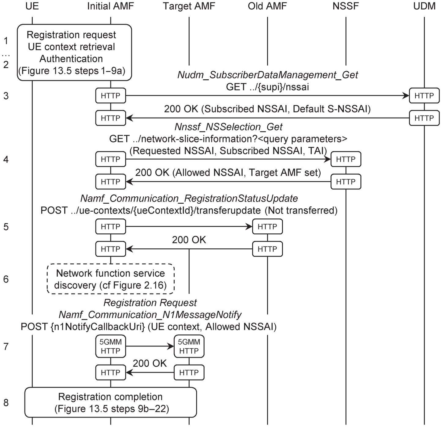
Figure 13.6 Registration procedure, including re‐allocation of the AMF.
Source: Adapted from 3GPP TS 23.502.
As in the previous example, the initial AMF receives a registration request, retrieves the UE context from the old AMF and optionally authenticates the mobile (steps 1 and 2). This time, however, the requested NSSAI is inconsistent either with the allowed NSSAI from the UE context, or with the AMF's capabilities, or with the mobile's new tracking area.
The UE context does not necessarily contain the subscribed NSSAI. If it does not, then the AMF contacts the UDM to retrieve the mobile's slice selection subscription data (3). The UDM's reply includes part of the access and mobility subscription data from earlier, by listing the slices in the subscribed NSSAI and identifying one of those slices as the default. The AMF then contacts the network slice selection function (NSSF), supplies the subscribed and requested NSSAIs, and identifies the mobile's tracking area (4). In response, the NSSF returns an allowed NSSAI for the mobile, and a suitable AMF set.
The initial AMF now notifies the old one that the registration has not yet completed (5). It may also need to contact the network repository function to discover the domain names of the AMFs that are within the target AMF set (6).
The initial AMF selects a target AMF, and it now has two possibilities. If network policy permits, then it can forward the mobile's registration request directly to the target AMF, using an HTTP POST to a notification URI that it retrieved during network function service discovery (7). The initial AMF includes the UE context and the allowed NSSAI, and the procedure continues from the step of NAS security activation. Alternatively, the initial AMF can ask the NG-RAN to re‐route the mobile's message, and can include the identity of the target AMF.
13.5 Deregistration Procedure
The deregistration procedure takes down a mobile's access to the 5G core network. It can be triggered either by the mobile (for example, if the user selects aeroplane mode or switches the mobile off) or by the network. Figure 13.7 shows an example for a mobile‐initiated deregistration from the state of RRC_CONNECTED [24].
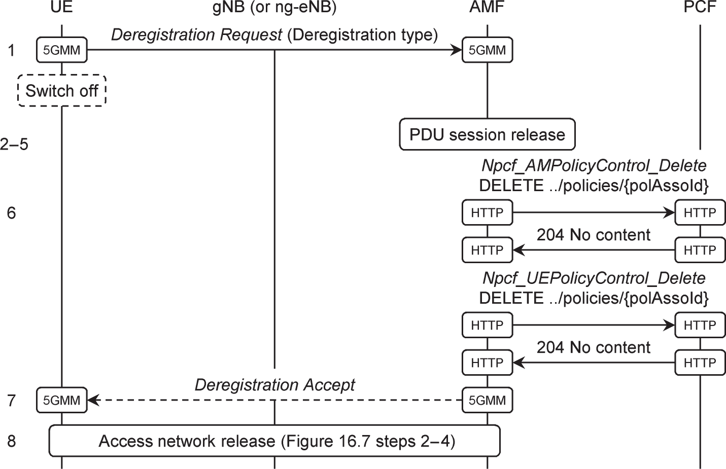
Figure 13.7 Mobile‐initiated deregistration procedure.
Source: Adapted from 3GPP TS 23.502.
To begin the procedure, the mobile sends a 5GMM Deregistration Request to the AMF and states its reason for doing so, either a normal deregistration or switching off (step 1). If the mobile is switching off, then it can do so now without waiting for the network's response.
If the mobile has any PDU sessions, then the AMF instructs the relevant SMFs to tear them down (2–5). The AMF also deletes the relevant policy associations with the PCF (6). However, it does not delete its record of the mobile's registration in the UDM. Instead, the AMF and mobile both retain information such as the mobile's identities and security keys, for use during the next registration procedure. If the mobile is not switching off, then the AMF accepts the deregistration request (7). Finally, the AMF instructs the NG-RAN to release its own resources for the mobile (8).
References
- 1 3GPP TS 23.502 (2019) Procedures for the 5G system (5GS); Stage 2 (Release 15), December 2019.
- 2 3GPP TS 38.300 (2019) NR; NR and NG‐RAN overall description; Stage 2 (Release 15), December 2019.
- 3 3GPP TS 23.122 (2019) Non‐access‐stratum (NAS) functions related to mobile station (MS) in idle mode (Release 15), March 2019.
- 4 3GPP TS 38.304 (2019) NR; User equipment (UE) procedures in idle mode and RRC inactive state (Release 15), December 2019.
- 5 3GPP TS 23.122 (2019) Non‐access‐stratum (NAS) functions related to mobile station (MS) in idle mode (Release 15), March 2019, Sections 3.1, 3.5, 4.4, 5.
- 6 3GPP TS 31.102 (2019) Characteristics of the Universal Subscriber Identity Module (USIM) application (Release 15), December 2019, Sections 4.2.5, 4.2.53, 4.2.54, 4.2.84, 4.2.91, 4.4.11.2.
- 7 3GPP TS 38.304 (2019) NR; User equipment (UE) procedures in idle mode and RRC inactive state (Release 15), December 2019, Section 5.1.1.
- 8 3GPP TS 38.304 (2019) NR; User equipment (UE) procedures in idle mode and RRC inactive state (Release 15), December 2019, Sections 5.2.1, 5.2.3, 5.3.
- 9 3GPP TS 38.215 (2019) NR; Physical layer measurements (Release 15), December 2019, Sections 5.1.1, 5.1.3.
- 10 3GPP TS 38.101‐1 (2019) NR; User equipment (UE) radio transmission and reception; Part 1: Range 1 standalone (Release 15), December 2019, Section 6.2.
- 11 3GPP TS 38.101‐2 (2019) NR; User equipment (UE) radio transmission and reception; Part 2: Range 2 standalone (Release 15), December 2019, Section 6.2.
- 12 3GPP TS 36.304 (2019) Evolved Universal Terrestrial Radio Access (E‐UTRA); User equipment (UE) procedures in idle mode (Release 15), December 2019, Sections 5.2.3, 5.3.
- 13 3GPP TS 38.331 (2019) NR; Radio resource control (RRC) protocol specification (Release 15), December 2019, Section 5.3.3.
- 14 3GPP TS 23.501 (2019) System architecture for the 5G system (5GS); Stage 2 (Release 15), December 2019, Section 6.3.5.
- 15 3GPP TS 38.413 (2019) NG‐RAN; NG Application Protocol (NGAP) (Release 15), December 2019, Section 8.6.1.
- 16 3GPP TS 36.331 (2019) Evolved Universal Terrestrial Radio Access (E‐UTRA); Radio resource control (RRC); Protocol specification (Release 15), December 2019, Section 5.3.3.
- 17 3GPP TS 23.401 (2019) General Packet Radio Service (GPRS) enhancements for Evolved Universal Terrestrial Radio Access Network (E‐UTRAN) access (Release 15), December 2019, Section 5.3.2.1.
- 18 3GPP TS 23.502 (2019) Procedures for the 5G system (5GS); Stage 2 (Release 15), December 2019, Section 4.2.2.2.2.
- 19 3GPP TS 38.300 (2019) NR; NR and NG‐RAN overall description; Stage 2 (Release 15), December 2019, Section 9.2.1.3.
- 20 3GPP TS 33.501 (2019) Security architecture and procedures for 5G system (Release 15), December 2019, Section 6.4.6.
- 21 3GPP TS 24.526 (2019) User equipment (UE) policies for 5G system (5GS); Stage 3 (Release 15), June 2019.
- 22 3GPP TS 24.501 (2019) Non‐access‐stratum (NAS) protocol for 5G system (5GS); Stage 3 (Release 15), December 2019, Sections 5.4.5, 8.2.11, Annex D.
- 23 3GPP TS 23.502 (2019) Procedures for the 5G system (5GS); Stage 2 (Release 15), December 2019, Section 4.2.2.2.3.
- 24 3GPP TS 23.502 (2019) Procedures for the 5G system (5GS); Stage 2 (Release 15), December 2019, Section 4.2.2.3.2.