
14
Security
This chapter covers the security procedures in the 5G system. To help define those procedures, the 3GPP specifications break down the 5G system into a number of different security domains. In previous generations, two of those have been particularly important: network access security, which protects the mobile's communications with the network over the air interface; and network domain security, which protects the network itself. 5G also introduces the concept of service‐based architecture domain security, which protects the network's service‐based interfaces using procedures that are different from the ones used elsewhere.
In this chapter, we will start by reviewing the underlying security techniques that 5G uses, and then work our way through each of its security domains in turn. The most important specification is the stage 2 description, TS 33.501 [1].
14.1 Security Principles
The 5G system is secured using several techniques whose underlying principles are common to all of its security domains. During authentication, two devices confirm that each other is a trusted device, not an intruder, and set up security keys for use by the procedures that follow. Ciphering, also known as encryption, ensures that intruders cannot read the data and signalling messages that two devices exchange.
Some national regulations restrict the use of encryption, which makes two other techniques important. Integrity protection detects any attempt by an intruder to modify the data or signalling messages that two devices exchange. It protects the system against problems such as man‐in‐the‐middle attacks, in which an intruder intercepts a sequence of signalling messages and modifies them in an attempt to take control of the target device. As part of that process, replay protection detects any attempt to play back a signalling message that an intruder has previously recorded, so as to prevent the intruder from spoofing the identity of the device that transmitted the message.
A final technique, particularly relevant for network access security, is confidentiality. The subscription permanent identifier (SUPI) is one of the quantities that an intruder needs in order to clone a mobile, so 5G avoids broadcasting it over the air interface. Instead, the network identifies the user by means of temporary identities. If the 5G core network knows the AMF region that the mobile is in (for example, during paging), then it uses the 40‐bit 5G‐S‐TMSI (temporary mobile subscriber identity). Otherwise (for example, during registration), it uses the longer 5G globally unique temporary identity (5G‐GUTI). In a feature that is new to 5G, a mobile can also identify itself using an encrypted version of the SUPI, which is known as the subscription concealed identifier (SUCI).
The 5G system also supports lawful interception [2-4]. This allows the police and security services to intercept traffic and signalling messages for individual users, subject to the appropriate national regulations.
14.2 Network Access Security
14.2.1 Network Access Security Architecture
Network access security refers to all the security procedures that involve the mobile, and involves a number of additional network functions. The most important is the authentication server function (AUSF), which manages the authentication procedures in the home network. The AUSF has three main roles, which are most apparent when the mobile is roaming. Firstly, the AUSF verifies that the visited network is a genuine network that has been authorized to serve the mobile, and is not a spoof network. Secondly, the AUSF authenticates the mobile on behalf of the home network, alongside the access and mobility management function's (AMF's) authentication on behalf of the visited network. Thirdly, the AUSF allows 5G to use the same authentication architecture for the cases of 3GPP and non‐3GPP access. That situation is different from LTE, in which a roaming mobile was authenticated by the visited network's mobility management entity when using 3GPP access, but by the home network's authentication, authorization and accounting (AAA) server when using non‐3GPP access technologies such as WiFi.
The other security functions are currently co‐located with network functions that we have already discussed in this book, although they might eventually be implemented separately. The security anchor function (SEAF) is co‐located with the AMF and manages the authentication procedures in the visited network. The authentication credential repository and processing function (ARPF) is co‐located with the function for unified data management (UDM). It stores the most important security keys and carries out security‐related calculations, so it has a similar role to the authentication centre (AuC) from 2G and 3G. Finally, the subscription identifier de‐concealing function (SIDF) is also co‐located with the UDM. Its role is to decrypt the SUCI.
Figure 14.1 shows the high‐level architecture. Authentication takes place between the mobile and the home network, specifically between the universal integrated circuit card (UICC) and the ARPF. At a minimum, the mobile has to support two authentication procedures: an enhanced version of the legacy 3GPP procedure that is known as 5G authentication and key agreement (5G AKA), and an Internet Engineering Task Force (IETF) protocol known as the improved extensible authentication protocol for 3G authentication and key agreement (EAP‐AKA′) [5]. If the mobile is roaming, then the SEAF has to support those procedures as well. On the other hand, a private 5G network can implement other authentication schemes, using algorithms that are downloaded onto the UICC.
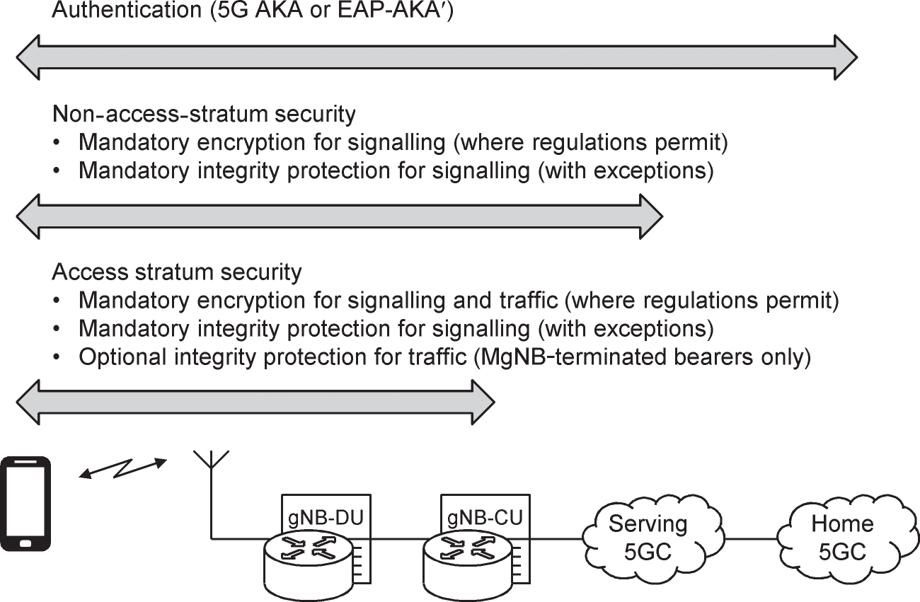
Figure 14.1 Network access security architecture.
Whenever regulations permit, non‐access stratum signalling messages between the mobile and the AMF are protected by encryption. They are also protected by integrity and replay protection, except for a few special cases such as emergency calls from mobiles that are in a limited service state. Access stratum signalling messages between the mobile and the master node are secured in the same way, with the protection extending to the gNB central unit on the grounds that the distributed unit may be at an insecure location.
Access stratum traffic is encrypted in the same way as signalling. A new feature in 5G is that access stratum traffic can also be protected by integrity and replay protection, although that is only supported in architectural options 2 and 4 for bearers that terminate in a master gNB.
14.2.2 Key Hierarchy
Network access security relies on shared knowledge of a user‐specific key, K, which is securely stored in the ARPF and securely distributed within the UICC. During the authentication procedure, the mobile and network confirm that each other has the correct value of K. They then compute a hierarchy of lower‐level keys, which are illustrated in Figure 14.2 and which are used by the lower‐level procedures that follow [6].

Figure 14.2 Network access security keys.
Source: Adapted from 3GPP TS 33.501.
From K, the ARPF and UICC derive two further keys, denoted CK and IK. 3G systems used those keys directly for ciphering and integrity protection. In 5G, they are used to derive a sequence of lower‐level keys, which are denoted KAUSF, KSEAF, KAMF and KgNB, and which are passed to the AUSF, SEAF, AMF and master node respectively. From KAMF, the mobile equipment and the AMF derive two further keys, denoted KNASenc and KNASint, which are used for encryption and integrity protection of non‐access stratum signalling messages. Similarly, the mobile equipment and the master node derive four further keys, denoted KRRCenc, KRRCint, KUPenc and KUPint, which are used for encryption and integrity protection of radio resource control (RRC) signalling messages and of user plane traffic. Each set of keys is identified by means of a key set identifier, denoted ngKSI.
K has either 128 or 256 bits, while CK and IK have 128 bits each. The other keys all have 256 bits, but the current algorithms for encryption and integrity protection only use the least significant 128. Future advances in computing technology may make 128‐bit keys insecure, but may also make the use of 256‐bit keys more feasible. If that happens, then 5G will be able to upgrade its algorithms to support 256‐bit keys with ease.
14.3 Network Access Security Procedures
14.3.1 Subscription Concealed Identifier
Usually, the mobile identifies itself to the 5G core network using a 5G globally unique temporary identity, from which its serving AMF can retrieve the corresponding subscription permanent identifier. However, there are a few situations in which that procedure fails. Examples include the very first use of the Universal Subscriber Identity Module (USIM), when the temporary identity does not yet exist, or after a database failure within the network.
In previous generations, the mobile reacted by quoting its permanent identity. That left a security weakness, which 5G solves by introducing the SUCI. Within the SUCI, the mobile's identity is concealed by means of public key encryption, using a public key that the home network operator has provisioned within the USIM. The mobile network and mobile country codes are left in plain text, so the information can be routed towards the correct home network, which recovers the mobile's identity using a private key that the UDM stores within the ARPF. The algorithm used is known as the elliptic curve integrated encryption scheme (ECIES) [9-11], which has the advantage over other public key techniques of achieving the same level of security using significantly shorter keys.
14.3.2 Authentication and Key Agreement
Depending on its internal policies, the AMF can initiate authentication during any procedure that takes the mobile from CM‐IDLE into CM‐CONNECTED, for example during the registration procedure from Chapter 13. Figure 14.3 shows one of the authentication procedures that can result, namely 5G authentication and key agreement [12].
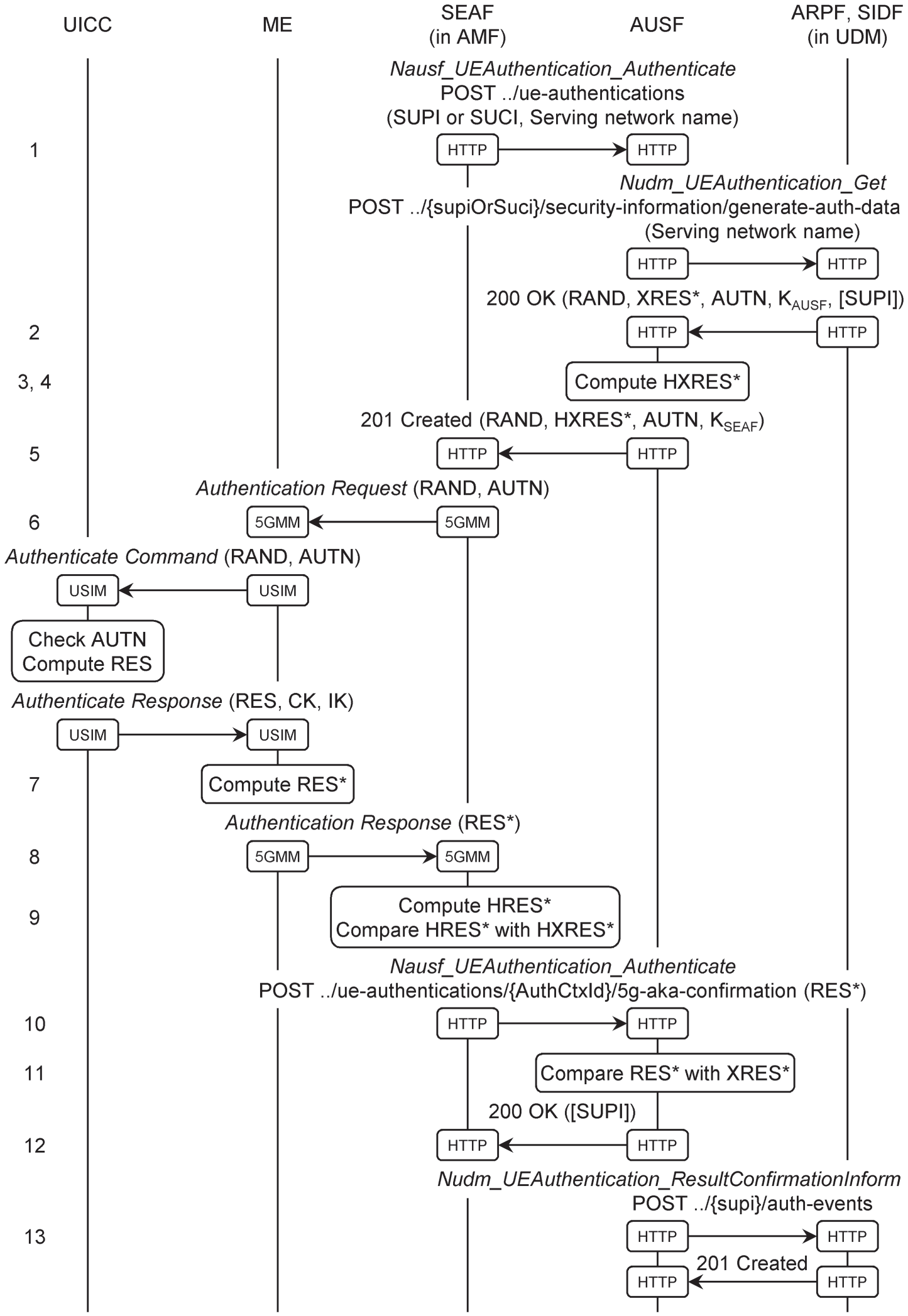
Figure 14.3 5G authentication and key agreement procedure.
Source: Adapted from 3GPP TS 33.501.
Triggered by a signalling message such as a registration request, the AMF selects an AUSF in the mobile's home network, and asks it to authenticate the mobile (step 1). The information elements include a serving network name that is constructed from the corresponding mobile network and mobile country codes, and the subscriber's permanent or concealed identity. On receiving the request, the AUSF first checks that the AMF is entitled to use the serving network name. It then forwards the information to the UDM, which creates a new resource that includes the subscriber's identity.
The next few steps take place inside the UDM. If the AUSF supplied the subscription concealed identifier, then the ARPF asks the SIDF to return the corresponding permanent identifier. The ARPF then looks up the network's copy of the user‐specific key K, and generates an authentication vector that contains four elements. The first of these is a random number, which is used as an authentication challenge to the mobile and is denoted RAND. The other three are all computed using RAND, K and the serving network name. XRES* is the expected response to the authentication challenge, which can only be correctly computed by a mobile that has the same value of K. AUTN is an authentication token, which demonstrates to the mobile that the network has the same value of K, and which includes a sequence number for use in replay protection. Finally, KAUSF is the home network's anchor key from Figure 14.2. The ARPF returns the authentication vector to the AUSF, along with any SUPI that it retrieved (2). Unlike in previous generations, 5G only supports the return of one authentication vector at a time.
The AUSF stores XRES* for later use by the home network's authentication procedure, and computes a derived version, denoted HXRES*, which is used for authentication in the visited network (3, 4). (Here, the prefix H has nothing to do with the home network: instead, it indicates that HXRES* is computed using a hashing algorithm.) The AUSF also stores any permanent identity that it received from the UDM, and computes the visited network's anchor key KSEAF. It then forwards the relevant authentication material to the AMF, and supplies a uniform resource identifier (URI) that the AMF should use for the subsequent confirmation (5). In turn, the AMF sends the random number and authentication token to the mobile (6).
Inside the mobile, the mobile equipment sends the random number and authentication token to the UICC. In the UICC, the USIM application examines the authentication token to check that the network has the same value of K and that the enclosed sequence number has not been used before. If it is happy, then it calculates the authentication response that was used in earlier 3GPP generations, denoted RES, by combining RAND with its own copy of K. It passes that response back to the mobile equipment, along with the values of CK and IK from Figure 14.2. The mobile equipment combines RES with its own understanding of the serving network name, so as to compute the 5G authentication response RES* (7). It also uses CK and IK to compute the mobile's values of KAUSF, KSEAF and KAMF. Although a little complicated, this process allows a mobile to access the 5G core network using a legacy USIM, and ensures that 5G network operators do not necessarily have to replace their subscribers' SIM cards.
The mobile then returns the authentication response to the AMF (8). That computes a hashed version of the mobile's response, denoted HRES*, and compares it with the value of HXRES* from earlier (9). If the two are the same, then it concludes that the mobile has the correct value of K and has therefore been authenticated successfully. The AMF confirms the authentication using the URI that it received from the AUSF and includes the mobile's original response RES* (10).
The AUSF compares the mobile's response with the expected response XRES* (11). If the two are the same, then the AUSF concludes not only that the mobile is authenticated, but also that the serving network quoted the same network and country codes to the home network and to the mobile. By combining this with its previous conclusion that the AMF was entitled to use those codes, the AUSF concludes that the serving network is genuine. The AUSF returns an acknowledgement to the AMF, and includes any permanent identity that it retrieved earlier (12). On receiving that acknowledgement, the AMF computes the key KAMF.
To conclude the procedure, the AUSF sends a confirmation to the UDM that the mobile has been authenticated successfully (13). The UDM can then link that confirmation to subsequent procedures. For example, it might only accept a serving network's request to register a mobile (Figure 13.5, step 14a), if the mobile has recently been authenticated by the same serving network.
14.3.3 Activation of Non‐access Stratum Security
At the end of the authentication procedure, the mobile and AMF both have new values of KAMF. During the security activation procedures, the two devices derive the keys for ciphering and integrity protection, and bring those keys into action [13].
The AMF activates non‐access stratum security immediately after authentication and key agreement, as shown in Figure 14.4. From KAMF, the AMF calculates the ciphering and integrity keys KNASenc and KNASint. It then sends the mobile a 5G mobility management (5GMM) message known as a Security Mode Command (step 1), which identifies the new key set and selects the security algorithms to use. The message is secured by integrity protection using the new value of KNASint, but is not ciphered, even if the mobile already has a valid set of security keys.

Figure 14.4 Non‐access stratum security mode command procedure. Source: Adapted from 3GPP TS 33.501.
The mobile computes its own copies of KNASenc and KNASint, and checks the integrity of the message in the manner described later in this chapter. If the message passes the integrity check, then the mobile starts uplink ciphering, and acknowledges the AMF's command using a 5GMM Security Mode Complete (2). On receiving the message, the AMF starts downlink ciphering.
14.3.4 Activation of Access Stratum Security
Access stratum security is activated in much the same way (Figure 14.5), but the steps are in a slightly different order. To trigger the process, the AMF computes the value of KgNB, and passes it to the master node as part of an NG application protocol (NG‐AP) Initial Context Setup Request (Figure 13.4, step 9c). The master node computes the access stratum's ciphering and integrity keys, and sends the mobile an RRC Security Mode Command (1) that selects the security algorithms to use. The mobile computes its own copies of the security keys, checks the integrity of the message and replies with an RRC Security Mode Complete (2). Unlike in the non‐access stratum procedure, neither of these messages is ciphered.

Figure 14.5 Access stratum security mode command procedure.
Source: Adapted from 3GPP TS 33.501.
In dual connectivity, the master node uses its copy of KgNB to generate a new key, denoted KSN. Using Xn application protocol (Xn-AP) signalling, the master node passes KSN to the secondary, which takes the key into action as its own value of KgNB. The secondary node might support different security algorithms from the master, so it can select different algorithms for communications with the mobile.
14.3.5 Key Handling During Mobility
Other procedures deal with key handling during mobility and state transitions [14]. If the master node's central unit remains unchanged as part of a handover, then it can optionally retain the old value of KgNB, depending on network policy. Otherwise, there are two ways to compute a new value. The first is a horizontal key derivation, in which the old master node uses the old value of KgNB to compute a new quantity, which is denoted KgNB*. It passes that quantity to the new master node, which brings it into action as the new value of KgNB. The second is a vertical key derivation, in which the AMF uses the value of KAMF to compute two intermediate quantities, known as next hop (NH) and next hop chaining counter (NCC). It passes those quantities to the new master node, which uses them to compute the new value of KgNB. The Xn‐based handover procedure in Chapter 16 uses both types of derivation, while an NG‐based handover uses vertical key derivation alone.
If the AMF changes, then the old AMF can optionally use another type of horizontal key derivation to compute a new value of KAMF from the old one, and can then pass the new key to the new AMF. If that happens, then the new AMF brings the new key into action using the same security mode command procedure as before, but indicates in step 1 that the mobile should perform its own horizontal key derivation, so as to update its own value of KAMF.
14.3.6 Key Handling During State Transitions
If the network releases a mobile's RRC connection and moves it to RRC_IDLE, then the mobile's access stratum security keys are all deleted. If, however, the network merely suspends a mobile's RRC connection and moves it to RRC_INACTIVE, then the mobile, master node and any secondary all retain their copies of the integrity key KRRCint, and of the access stratum security key KgNB. Later, they can use the first of those keys to check their subsequent access stratum signalling messages, and can use the second to resume the RRC connection without the need to communicate with the core.
During the deregistration procedure, the mobile and AMF delete their copies of KNASenc and KNASint, but retain their copies of KAMF. During a subsequent registration request, the mobile re‐calculates its previous copies of KNASenc and KNASint. The mobile uses the first key to encrypt most of the information elements in the registration request, leaving in plain text the ones that are needed for message routing and security establishment. It uses the second key to secure the message by integrity protection.
14.3.7 Ciphering
Ciphering ensures that intruders cannot read the information that is exchanged between the mobile and the network [15]. The packet data convergence protocol ciphers data and signalling messages in the air interface's access stratum, while the 5G mobility management protocol ciphers signalling messages in the non‐access stratum.
Figure 14.6 shows the ciphering process. The transmitter uses its ciphering key and other information fields to generate a pseudo‐random key stream, and mixes that with the outgoing data using an exclusive‐OR operation. The receiver generates its own copy of the key stream and repeats the mixing process so as to recover the original data.

Figure 14.6 Ciphering.
Source: Adapted from 3GPP TS 33.501.
5G currently supports four encryption algorithms, denoted NEA, which are the same ones used by LTE. It is mandatory for the mobile to support two algorithms, namely SNOW 3G, which was originally used in the Release 7 standards for UMTS, and the Advanced Encryption Standard (AES). It is optional for the mobile to support a third algorithm, known as ZUC, which is mainly intended for use in China. The fourth is a null encryption algorithm in which the air interface does not implement ciphering at all.
14.3.8 Integrity Protection
Integrity protection allows a receiver to detect modifications to data packets or signalling messages, as a protection against problems such as man‐in‐the‐middle attacks. Integrity protection is implemented in the same protocols as ciphering, and is illustrated in Figure 14.7 [16].

Figure 14.7 Integrity protection.
Source: Adapted from 3GPP TS 33.501.
The transmitter uses several information fields, notably the outgoing information, the integrity key, and a counter that is incremented for each transmission. Using these fields, the transmitter computes a 32‐bit message authentication code (MAC) and appends it to the outgoing data. The receiver separates the integrity field from the rest of the incoming data, and computes the expected authentication code XMAC. If the observed and expected codes differ, then the receiver concludes either that the data have been modified or that they have been replayed using an old value of the counter. In both cases, the incoming data are discarded.
Integrity protection is mandatory for almost all of the signalling messages that the mobile exchanges with the network. There are four algorithms, denoted NIA, which are the same ones used for encryption. The null integrity algorithm is only allowed in a few special cases, for example emergency calls from mobiles that are in a limited service state with no access to the home network. Integrity protection is optional for traffic, and is only supported for bearers that terminate in a master gNB.
14.4 Network Domain Security
14.4.1 Network Domain Security Architecture
The term network domain security (NDS) applies to reference points in the 5G fixed network that do not have a corresponding service‐based interface. Some of those reference points may already be physically secure, for example if they are confined within a physical site that the network operator controls. The others are vulnerable to intrusion and have to be secured. Examples include the interfaces between different sites in the radio access network, which are often managed by a third party, and the ones between different sites in the network operator's core.
Figure 14.8 shows the architecture used [17]. In most cases, authentication, encryption, integrity protection and replay protection are mandatory for any reference point that is not physically secure. The only exceptions are the legacy signalling reference points to the evolved packet core and an external application function, namely N26 and Rx, for which it is mandatory to support those procedures but optional to use them.
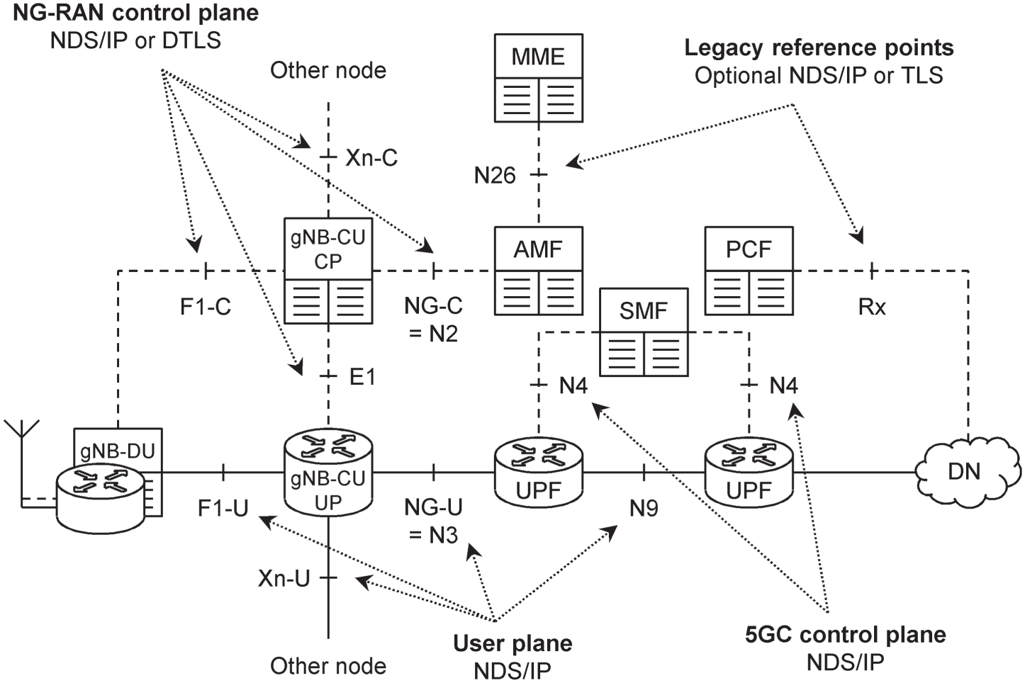
Figure 14.8 Network domain security architecture.
14.4.2 Network Domain Security Protocols
Network domain security can be implemented using two main protocols, namely IP network layer security and transport layer security (TLS) [18,19]. Support of IP network layer security is mandatory for all the reference points in Figure 14.8. To use it, two devices first authenticate each other using a certificate‐based protocol known as Internet Key Exchange version 2 (IKEv2) [20], and set up a security association that includes lower‐level keys for encryption and integrity protection.
The devices then implement those procedures using the internet protocol security (IPSec) encapsulating security payload (ESP) [21]. It is optional for a network operator to support ESP transport mode, which encrypts the payload of an IP packet but leaves the headers in plain text for routing purposes. It is mandatory for the operator to support ESP tunnel mode, in which the original IP headers are also encrypted, and new headers are added for routing.
In the core network, an IPSec tunnel can be implemented using a separate device known as a security gateway (SEG). The originating gateway receives an outgoing IP packet from a network function, encrypts it and adds a new IP header that routes the packet to the destination gateway. That device then decrypts the original packet and sends it on. In the radio access network, the gateway's functions usually form part of the base station itself.
Transport layer security is an alternative protocol which implements authentication, encryption and integrity protection immediately above a reliable TCP transport layer. Datagram transport layer security (DTLS) is a variant which was originally designed for use over UDP [22], and which was adapted further for use over the stream control transmission protocol (SCTP) [23]. Support for DTLS over SCTP is mandatory for the control plane reference points in the radio access network. The original form of TLS is only used by the N26 and Rx reference points, and in some cases by the service‐based interfaces that we will discuss in Section 14.5. If the protocol is implemented, then support for versions 1.3 and 1.2 is mandatory [24,25], while version 1.1 is optional.
14.5 Service‐based Architecture Domain Security
14.5.1 Security Architecture
The term service‐based architecture domain security applies to the service‐based interfaces in the 5G core. From the viewpoint of security, there are three types of service‐based interface, which are illustrated in Figure 14.9. The first covers the service‐based interfaces inside a single operator's network, which are secured using IP network layer security or TLS in the manner described in Section 14.4.2 [26].

Figure 14.9 Service‐based interface security architecture.
Service‐based interfaces between two networks are implemented over the N32 reference point, which connects the security edge protection proxies (SEPPs) that we introduced in Chapter 2. If the N32 reference point is a direct interconnection that does not traverse the IP packet exchange (IPX), then it is secured using TLS alone.
However, a different scenario arises if the N32 reference point traverses the IPX [27]. Each network operator communicates with its own trusted IPX service provider, and has a business relationship through which the service provider may wish to read, and even modify, individual information elements in the HTTP/2 and JavaScript Object Notation (JSON) signalling messages. (One example is the modification of HTTP/2 headers for routing purposes, while other examples might cover the provision of value‐added services by the IPX.) Other service providers could also be involved, but they just forward the messages transparently.
For those interfaces, security at the network or transport layer would be inappropriate. Instead, the SEPPs secure most of the signalling messages at the application layer, by applying encryption and integrity protection to individual HTTP/2 and JSON information elements, and by allowing the IPX service providers to make authorized modifications to them.
Figure 14.10 shows the architectural details. In the diagram, a consumer network function (cNF) requests a service from a producer network function (pNF) in another operator's network. The networks communicate using SEPPs – denoted cSEPP and pSEPP respectively – and have business relationships with their own IPX service providers, which are denoted cIPX and pIPX.

Figure 14.10 Principles of secure message delivery over N32‐f.
The N32 reference point has two components. N32‐c carries HTTP/2 signalling messages that manage the relationship between the two SEPPs. Those messages are secured by TLS, so they cannot be read or modified by the intervening IPXs. N32‐f forwards subsequent HTTP/2 signalling messages between the two network functions. Those messages are secured at the application layer by JSON object signing and encryption (JOSE), a security framework that supports integrity and replay protection by means of JSON web signature (JWS) [28] and supports encryption by means of JSON web encryption (JWE) [29]. We will discuss the details of both components next.
14.5.2 Initial Handshake Procedures over N32‐c
After establishing communications, the two SEPPs authenticate each other and set up a secure TLS connection over N32‐c. They then configure their subsequent communications over N32‐f in an HTTP/2 signalling procedure that has three steps [30]. During the first, the SEPPs agree the mechanism that they will use, either transport layer or application layer security. In the case of application layer security, they proceed to the second step of the procedure, in which they agree the security algorithms to use.
The richest step is the third one, in which the two SEPPs agree a policy for protecting the information that they will exchange. That policy has two parts. The first part lists the information elements that the SEPPs will protect by encryption and integrity protection. These include authentication vectors, cryptographic material, any location data such as a mobile's cell identity, and usually the subscription permanent identifier. The second part lists the information elements that the two IPXs can modify and is derived from the modification policies that the network operators already have with their IPXs.
14.5.3 Forwarding of JOSE Protected Messages over N32‐f
Once the handshake has completed, the two SEPPs protect subsequent HTTP/2 signalling messages using the procedure shown in Figure 14.11 [31,32].

Figure 14.11 Procedure for secure message delivery over N32‐f.
Source: Adapted from 3GPP TS 33.501.
To start the procedure, the consumer network function sends an HTTP/2 request to the producer, which the consumer's network routes through the corresponding SEPP (step 1). The SEPP reformats the request by copying individual HTTP/2 and JSON information elements into two JSON objects, which are denoted
dataToIntegrityProtect
and
dataToIntegrityProtectAndCipher
. As the names imply, the SEPP secures the first of those objects by integrity protection, and the second by integrity protection and ciphering (2). The SEPP then forwards the information to the consumer's IPX as the payload of an HTTP/2 POST (3).
The IPX modifies the
dataToIntegrityProtect
object, in accordance with the rules defined by its business relationship with the consumer's network. It then appends the modifications to the payload as a new JSON object, denoted
modifications
(4). That object is signed by means of JSON web signature so as to certify its origin. The IPX then forwards the message towards the producer's IPX (5), which evaluates the first IPX's modifications and applies its own in a similar way (6). In turn, the producer's IPX forwards the message to the producer's SEPP (7).
The producer's SEPP checks the integrity of the incoming message, decrypts the
dataToIntegrityProtectAndCipher
object and reconstructs the original HTTP/2 request (8). It then checks the integrity of the two IPXs' modifications, verifies that they are compliant with the modification policy established earlier and applies them. Finally, the SEPP delivers the HTTP/2 request to the producer network function (9). The HTTP/2 response is handled in a similar way.
References
- 1 3GPP TS 33.501 (2019) Security architecture and procedures for 5G system (Release 15), December 2019.
- 2 3GPP TS 33.126 (2019) Security; Lawful interception requirements (Release 15), December 2018.
- 3 3GPP TS 33.127 (2019) Security; Lawful interception (LI) architecture and functions (Release 15), September 2019.
- 4 3GPP TS 33.128 (2019) Security; Protocol and procedures for lawful interception (LI); Stage 3 (Release 15), December 2019.
- 5 IETF RFC 5448 (2009) Improved extensible authentication protocol method for 3rd generation authentication and key agreement (EAP‐AKA'), May 2009.
- 6 3GPP TS 33.501 (2019) Security architecture and procedures for 5G system (Release 15), December 2019, Section 6.2.
- 7 3GPP TS 33.501 (2019) Security architecture and procedures for 5G system (Release 15), December 2019, Section 6.12.2, Annex C.
- 8 3GPP TS 23.003 (2019) Numbering, addressing and identification (Release 15), September 2019, Section 2.2B.
- 9 Gayoso, M.,.V., Hernández, E.,.L., and Sánchez, Á.,.C. (2010). A survey of the elliptic curve integrated encryption scheme. Journal of Computer Science and Engineering 2 (2): 7–13.
- 10 SECG (2009) Standards for efficient cryptography 1 (SEC 1): Elliptic curve cryptography, Version 2.0, May 2009.
- 11 SECG (2010) Standards for efficient cryptography 2 (SEC 2): Recommended elliptic curve domain parameters, Version 2.0, January 2010.
- 12 3GPP TS 33.501 (2019) Security architecture and procedures for 5G system (Release 15), December 2019, Sections 6.1.2, 6.1.3.2, 6.1.4.
- 13 3GPP TS 33.501 (2019) Security architecture and procedures for 5G system (Release 15), December 2019, Section 6.7.
- 14 3GPP TS 33.501 (2019) Security architecture and procedures for 5G system (Release 15), December 2019, Sections 6.8, 6.9, 6.10.
- 15 3GPP TS 33.501 (2019) Security architecture and procedures for 5G system (Release 15), December 2019, Annex D.2.
- 16 3GPP TS 33.501 (2019) Security architecture and procedures for 5G system (Release 15), December 2019, Annex D.3.
- 17 3GPP TS 33.501 (2019) Security architecture and procedures for 5G system (Release 15), December 2019, Section 9.
- 18 3GPP TS 33.210 (2019) 3G security; Network domain security (NDS); IP network layer security (Release 15), September 2019.
- 19 3GPP TS 33.310 (2018) Network domain security (NDS); Authentication framework (AF) (Release 15), December 2018.
- 20 IETF RFC 7296 (2014) Internet Key Exchange Protocol Version 2 (IKEv2), October 2014.
- 21 IETF RFC 4303 (2005) IP encapsulating security payload (ESP), December 2005.
- 22 IETF RFC 6347 (2012) Datagram Transport Layer Security Version 1.2, January 2012.
- 23 IETF RFC 6083 (2011) Datagram transport layer security (DTLS) for stream control transmission protocol (SCTP), January 2011.
- 24 IETF RFC 8446 (2018) The Transport Layer Security (TLS) Protocol Version 1.3, August 2018.
- 25 IETF RFC 5246 (2008) The Transport Layer Security (TLS) Protocol Version 1.2, August 2008.
- 26 3GPP TS 33.501 (2019) Security architecture and procedures for 5G system (Release 15), December 2019, Section 13.1.
- 27 3GPP TS 33.501 (2019) Security architecture and procedures for 5G system (Release 15), December 2019, Section 13.2.
- 28 IETF RFC 7515 (2015) JSON web signature (JWS), May 2015.
- 29 IETF RFC 7516 (2015) JSON web encryption (JWE), May 2015.
- 30 3GPP TS 29.573 (2019) 5G System; Public land mobile network (PLMN) interconnection; Stage 3 (Release 15), October 2019, Sections 5.2, 6.1.
- 31 3GPP TS 33.501 (2019) Security architecture and procedures for 5G system (Release 15), December 2019, Section 13.2.4.
- 32 3GPP TS 29.573 (2019) 5G system; Public land mobile network (PLMN) interconnection; Stage 3 (Release 15), October 2019, Sections 5.3, 6.2.