2
MAC Layer Protocol for Wireless Security
Sushmita Kumari* and Manisha Bharti
National Institute of Technology, Delhi, India
Abstract
Media access control (MAC) is one of the sub-layers of the data link layer (Layer 2) in OSI (open systems interconnection) model. The MAC layer provides a unique id and controls the access mechanism of channels in order to interface with other nodes over shared channel by using MAC protocol. MAC address is very helpful for delivering a data packet over an electronic network, which is not possible in the case of postal addresses. Data encapsulation, including frame assembly before transmission, and frame parsing/error detection during and after reception are the two main duties of the MAC.
Keywords: MAC layer, protocols, deterministic access, channelization, OSI model, deterministic access
2.1 Introduction
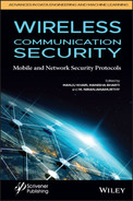
The Open Systems Interconnection Model (OSI Model) is a theoretical framework for describing the functions of a networking system. The connections between computing systems are classified into seven abstraction levels in the OSI reference model: Physical, Data Link, Network, Transport, Session, Presentation, and Application. The data link layer is divided into two sub-layers: Media access control (MAC) and Logical link control (LLC). MAC provides flow control and multiplexing for device transmissions over a network. (LLC) provides flow and error control over the physical medium as well as identifies line protocols.
2.2 MAC Layer
Medium access control (MAC) is a sub-layer of the data link layer presented in the OSI model. MAC layer allows having control of the devices which can be accessed on the share network [1]. To ensure that all devices may access the network within a period, some level of control is required, initiating in allowable access and response times. It can be characterized in different ways which are described below.
2.2.1 Centralized Control
A centralized controller polls devices to find out when each station is allowed to access and transmit data. Stations transmit when they are asked to or when a request for station broadcasting is acknowledged and approved. Polling necessitates the transmission of control packets, which adds overhead and reduces throughput in comparison to the raw bandwidth available.
2.2.2 Deterministic Access
In the deterministic access method, each station has the assurance of being able to communicate within a certain time frame. Deterministic access is also known as non-contentious, because the devices do not contend for access; rather access is controlled on a centralized basis.
2.2.3 Non-Deterministic Access
Non-deterministic media access control puts access control liabilities on the individual stations. This is commonly addressed as Carrier Sense Multiple Access (CSMA). It is decentralized, which is used in Ethernet and other bus oriented LANs, before access to the medium to send data [2]. It is of two types: CSMA/CD and CSMA/CA. In CSMA each station checks if there is any collision in the shared medium.
2.3 Functions of the MAC Layer
The MAC layer provides the shared link addresses: all devices have a unique id of 48 bits (6 bytes) known as the “MAC address”. The first three bytes describe the manufacturer of the network equipment. As a result, any network adapter (WLAN, Ethernet, or other) has a MAC address that is supposed to be unique. Sending packets on the network with the device’s MAC address can be used to communicate with it [3].
The MAC address is defined the same way in other IEEE-specified protocols as Ethernet or Token Ring. This permits stations from various types of networks to communicate with one another: all that is required is the use of “bridges” to connect different networks (bridge). MAC also initiates the frame transmission and recovery from transmission failure.
2.4 MAC Layer Protocol
MAC layer protocols operate at layer 2 that is Data Link Layer as shown in Figure 2.1 and its sub layer is shown in Figure 2.2. When multiple stations want to transmit data in sharable link like bus topology at same time, there is a chance of collision, which can lead to wastage of data [4]. Therefore to reduce the collisions different types of MAC protocols are required [5].
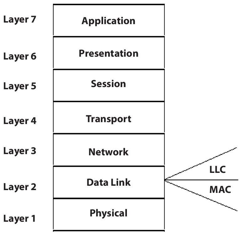
Figure 2.1 OSI model representing MAC layer.
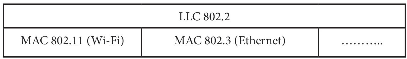
Figure 2.2 Sub-layer of data link layer.
MAC layer protocols are classified as follows: (shown in Figure 2.3)
Figure 2.3 Classification of MAC layer protocols.
2.4.1 Random Access Protocol
In this kind of protocol all stations have the same priority [6]. Depending on the status of the medium, any station can transfer data in sharable link whenever they are ready. It has two features:
- They can send data any time without fixed timing.
- There is no set order in which stations deliver data.
It is further classified as:
- ALOHA:
This protocol is based on LAN, but it can also be used for shared media. Multiple stations might broadcast data at the same time, which might result in collisions and jumbled data.
- Pure Aloha:
In pure aloha, any station can transmit data at any time. If data is transmitted from one station to another station without any collision then acknowledgement (ack) is being sent. If ack is not received for a given time then station waits for a certain time, say Tb, before resending the data. Because different stations take varying amounts of time to wait, the chances of another accident are reduced as shown in Figure 2.4.
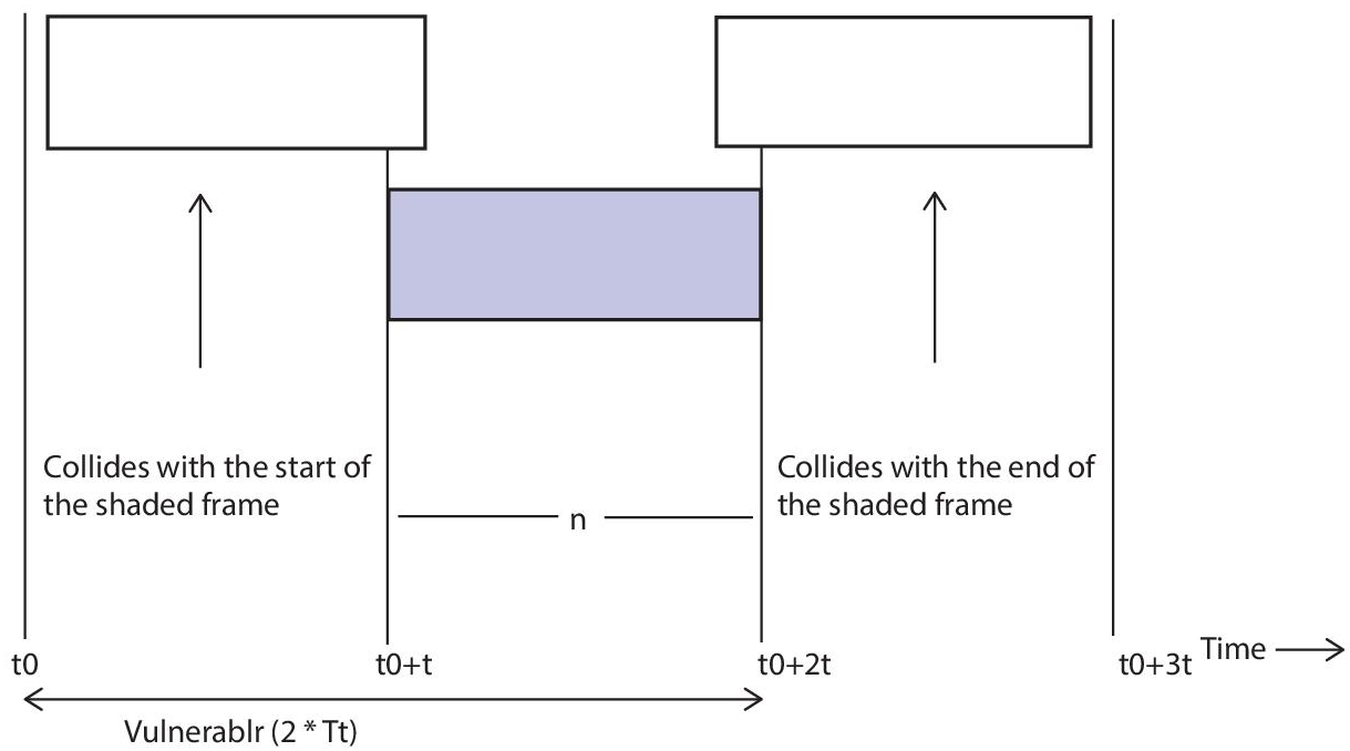
Figure 2.4 Pure Aloha.
- Slotted Aloha:
In slotted aloha, unlike pure aloha, we split the time into slots and any transmission will only occur at the beginning of each slot; otherwise stations have to stay for next available slot. This lowers the chances of an interference as shown in Figure 2.5.
- CSMA - In CSMA each station first senses the shared channel whether it is busy or not and according to that it transmits the data. It reduces the collision to a large extent. It transfers data if the channel is idle; else, it waits for the channel to become idle. However, because of the propagation delay, there is still a probability of a collision in CSMA.
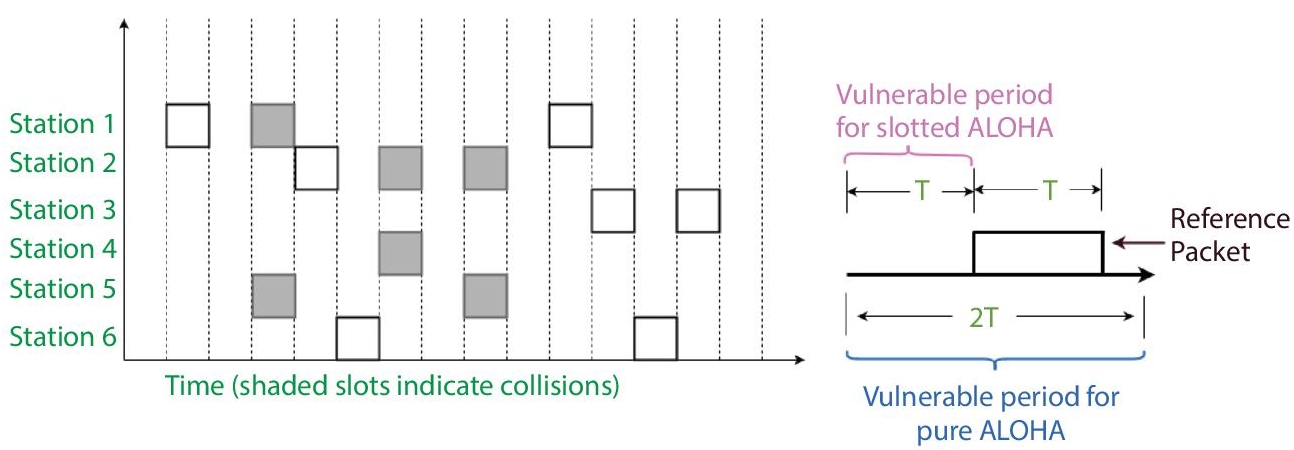
Figure 2.5 Slotted Aloha.
CSMA access modes -
1-persistent: In this method, node continuously sense the medium whether it is busy or not. If it senses medium is not busy it will transmit the data. Worst case can occur when each station senses the medium at the same time and it is not busy, node will transmit the data immediately and chances of collisions will be severe.
P-persistent: In this method node doesn’t send the data immediately when the shared medium is idle, it transmits data with probability p which have value between 0 to 1; otherwise it will become 0-persistent at p equals to 0 and 1-persistent at p equals to 1. Wi-Fi and packet radio technologies both use it.
O-persistent: The importance of nodes is determined ahead of time, and transmission takes place in that order. In this method node waits for some random time if the medium is busy. And after that time it again senses the medium. Collisions will be less compared to 1-persistent.
- (CSMA/CD (collision detection)) – The CSMA technique does not specify what should be done in the event of a collision. To deal with collisions, the carrier sense multiple access with collision detection (CSMA/CD) method is added to the CSMA algorithm. The size of a frame in CSMA/CD must be large enough for the sender to identify a collision while sending the frame [7]. Assume that a station successfully sent data packets to their destination; nevertheless, this is only the best case scenario; thus, we must consider the worst case situation, in which there will be conflict slots as shown in Figure 2.6. Contention slots are those that, due to a collision, are unable to transmit their travel.
- CSMA/CA (collision avoidance) - The sender receives acknowledgement signals as part of the collision detection procedure. The data is successfully delivered if there is just one signal (its own) and collision will happen for two signals. In wired networks, however, this is not the case; hence CSMA/CA is employed.
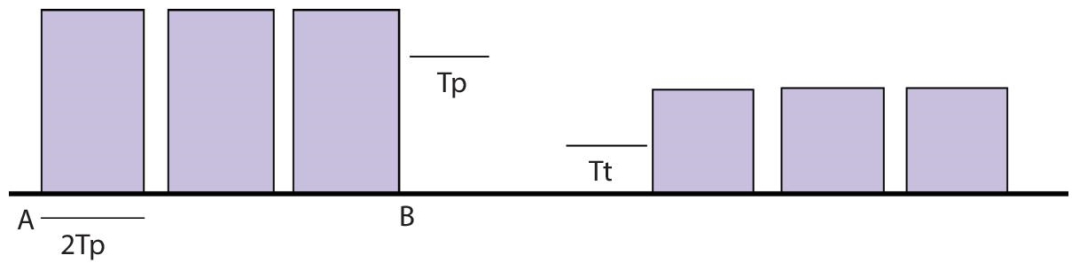
Figure 2.6 Assume A station communicated data but collided, wasting 2Tp in the worst-case scenario, and then some station B discovered a way to transfer the data, which took.
CSMA/CA avoids collision by:
Inter-frame space – The station checks whether the shared medium is busy or not and if it is free, it does not broadcast data right away so that it can reduce the collision. It waits for a period of time known as Inter-frame space. After that, it checks to see if the medium is still idle. The length of the IFS is determined by the station’s priority.
Contention Window – This refers to the quantity of time that is split up into equal slots. When the transmitter is prepared to transfer data, it selects a random number of slots as the hold time. If the medium becomes busy, the procedure is not restarted in its entirety; rather, the timer is restarted when the medium becomes free again.
Acknowledgement – If the sender does not receive acknowledgement before the timer expires, the data is resent.
2.4.2 Controlled Access Protocols
In this method, to establish which station has the authority to send, the stations exchange data. To avoid interference over shared link, it only enables one station to send at a time.
The three methods of these protocols are as follows:
- Reservation
- Polling
- Token Passing
- Reservation - A station must use the reservation mechanism to generate a reservation before transferring data.
The reserve period is divided into N slots if there are N stations, and one slot is assigned to each station. If station 1 has to transmit the data, at that time other stations are restricted to take action. In general, by adding a 1 bit into ith slot, ith station can advertise that it has a frame to deliver. Each station knows which stations want to transmit once all N slots have been examined.
The next reserve interval begins when the transmission of data has ended. Therefore it reduces the chances of collision as everyone knows who will be next. This concept is explained by the following Figure 2.7.
- Polling - The polling procedure is analogous to a roll call in class. A controller, like the instructor, transmits the data to each station in turn. One serves as the primary station (controller), while the others serve as subsidiary stations. The role of a controller is that all data should exchange through it. The address of the node being selected for access is included in the message sent by the controller.
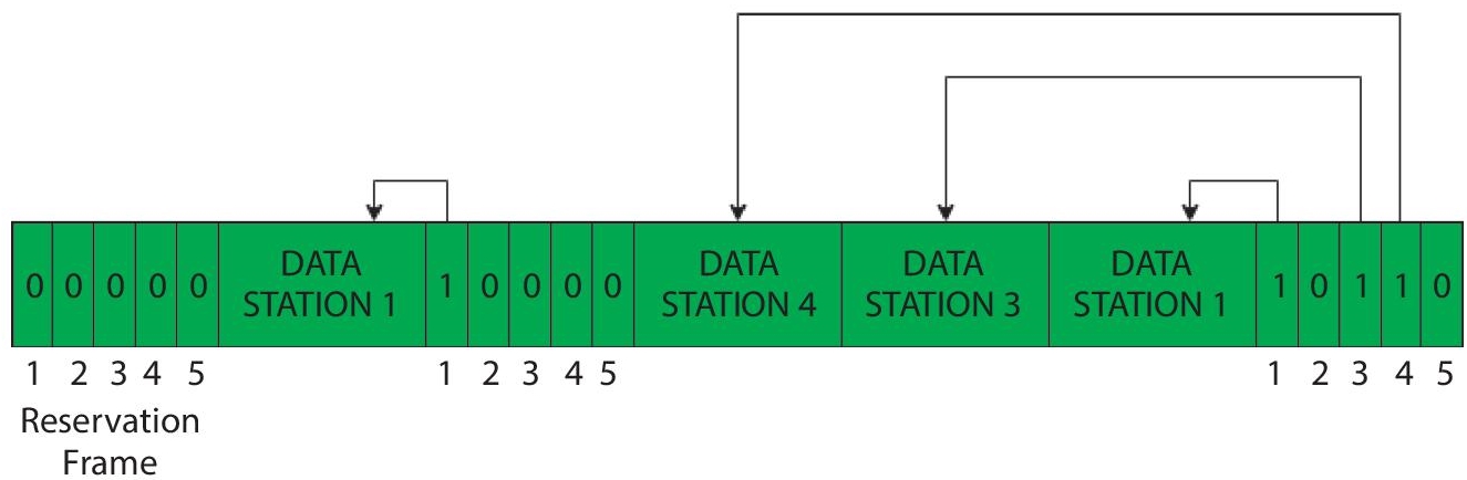
Figure 2.7 Five stations and slot reservation frame.
Despite the fact that all nodes get the message, only the one to whom it is addressed responds and provides data. A “poll reject” (NAK) message is usually returned if there is no data. The polling messages have a large overhead, and the controller’s reliability is highly dependent as explained in Figure 2.8.
- Token passing – In this method, stations are linked with each other in the form of ring and managed by tokens as shown in Figure 2.9. A token consists of particular patterns and pass on from one station to another in fixed order. In Token bus, each station uses the bus to deliver tokens to the next station in a predetermined order.
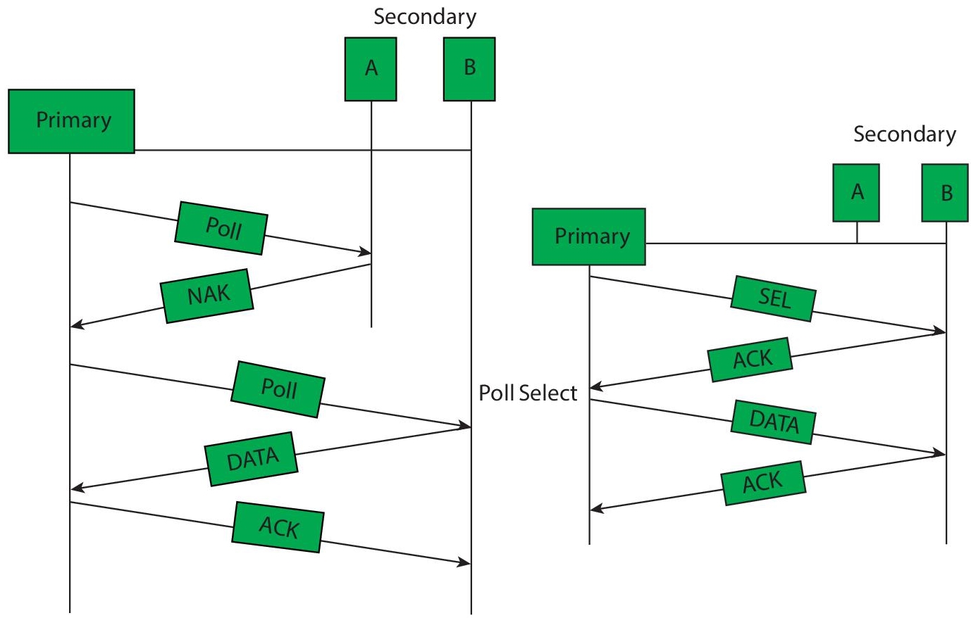
Figure 2.8 Polling process.
The token denotes the ability to send in all conditions. When a station receives the token and has a frame waiting to be transmitted, it might send it before sending the token to the next station. It just passes the token if there is no awaiting frame. Each station must wait for all P stations to send the token to their neighbours, as well as the other P – 1 station to broadcast a frame if they have one, after transmitting a frame. There is a problem with token duplication or loss, as well as the insertion and removal of additional stations, which must be solved in order for this scheme to function correctly and reliably.
2.4.3 Channelization
Channelization is categorized in terms of frequency, time and code. They are explained as follows:
- Frequency Division Multiple Access (FDMA) – It provides chunks of frequency spectrum to each user for data transmission. Generally the data is transmitted at baseband and modulated at varying radio frequencies.
- Time Division Multiple Access (TDMA) – It allows multiple users to share a common frequency band by allocating different time slots. It is used in GPRS, GSM, etc. [8].
- Code Division Multiple Access (CDMA) – All transmissions are carried on a single channel at the same time. There is no such thing as bandwidth or temporal division. Similarly, data from many stations can be delivered in several coding patterns at the same time.
2.5 MAC Address
The physical address that distinctively recognizes each device on a network is known as the MAC address shown in Figure 2.10. We need two addresses to communicate between two networked devices: an IP address and a MAC address. It’s assigned to each device’s NIC (Network Interface Card) that may connect to the internet [9].
Media Access Control, often known as Physical Address, Hardware Address, or BIA, is an acronym for Media Access Control (Burned in Address). It has a globally unique MAC address, which implies that no two devices can have the same MAC address. It is expressed in a hexadecimal format on each device, such as 22:0B:42:8C:12:72. It is provided by the device’s manufacturer at the time of manufacture and is built in the device’s NIC, which cannot be modified ideally. It’s 12-digits long and 48 bits long, with the first 24 bits utilised for OUI (Organization Unique Identifier) and the remaining 24 bits for NIC/vendor-specific information [10].
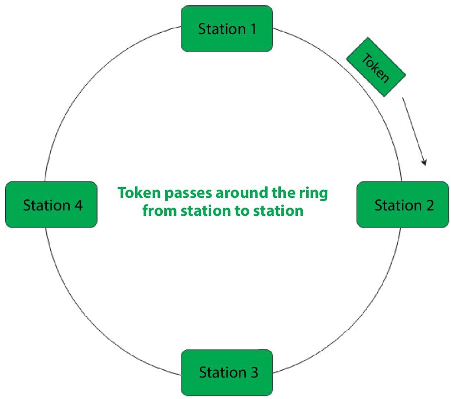
Figure 2.9 Token passing process.
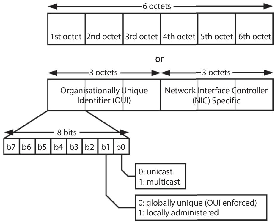
Figure 2.10 48-bit MAC address structure.
2.6 Conclusion and Future Scope
In this chapter many MAC protocols have been explained. If we want improve the performance many other protocols are also feasible [11]. Interaction with the MAC layer can provide congestion management information to other layers as well as improve routing decisions. However, improving the MAC protocol can enhance communication reliability and energy efficiency dramatically. The field of wireless sensor networks (WSN) MAC protocols has gotten a lot of attention from the scientific community [12]. WSN MAC protocol classification is introduced with the goal of improving performance which can be a topic of future research. At the end, open research questions are suggested.
Future purpose should concentrate on achieving to reduce delay, assurance in service quality, reducing interference and, finally, optimising power consumption; a set of needs common to wireless sensor networks [13].
References
- 1. IEEE Standards for “local and metropolitan area networks: overview and architecture” IEEE Std 802–2001 (Revision of IEEE Std 802–1990), 2001.
- 2. S. Yun, Y. Yi, J. Shin and D. Y. Eun, “Optimal CSMA: A survey,” 2012 IEEE International Conference on Communication Systems (ICCS), 2012, pp. 199-204, doi: 10.1109/ICCS.2012.6406138.
- 3. Flore, D.; 3GPP. Evolution of LTE in Release 13; 3GPP: Sophia Antipolis, France, 2015.
- 4. M. Leon Chavez M, “Fieldbus and real time MAC protocols,” presented at the IFAC Conf. SICICA 2000, Buenos Aires, Argentina.
- 5. A. El-Hoiydi and J.-D.Decotignie, “WiseMAC: an ultra low power MAC protocol for the downlink of infrastructure wireless sensor networks,” in Ninth International Symposium on Computers and Communications, 2004. Proceedings. ISCC 2004, 2004, vol. 1, pp. 244-251 Vol. 1.
- 6. J.-P. Thomesse, “Fieldbus Technology in Industrial Automation,” in Proceedings of the IEEE, vol. 93, no. 6, pp. 1073-1101, June 2005, doi: 10.1109/ JPROC.2005.849724.
- 7. Carrier sense multiple access with collision detection (CSMA/CD) access methodand physical layer specifications,” IEEE Std 802.3-2005 (Revision of IEEE Std 802.3-2002 including all approved amendments), vol. Section 1, pp. 0_1–594, 2005.
- 8. Muhammad, Tufail, et al. ”Energy-Efficient TDMA-based MAC (D-TDMAC) Protocol for Dynamic Sensing Applications in WSNs.” World Applied Sciences Journal 31.5 (2014), pp. 949-953.
- 9. “Supplement to IEEE Standard for Information Technology -Telecommunications and Information Exchange Between Systems - Local and Metropolitan Area Networks - Specific Requirements - Part 11: Wireless LAN Medium Access Control (MAC) and Physical Layer (PHY) Specifications: Higher-Speed Physical Layer Extension in the 2.4 GHz Band,” IEEE Std 802.11b-1999, pp. 1–90, 2000.
- 10. W. Ye, J. Heidemann, and D. Estrin, “Medium Access Control with Coordinated Adaptive Sleeping for Wireless Sensor Networks,” IEEE/ACM Trans. Netw., vol. 12, no. 3, pp. 493-506, Jun. 2004.
- 11. “Medium Access Control Protocols for Wireless Sensor Networks Classifications and Cross-Layering”, Saud Althobaitia, Manal Abdullah in International Conference on Communication, Management and Information Technology (ICCMIT 2015).
- 12. A. Pranali, N. Girigosavi, and G. Palan, “A mac protocol with interference avoidance mechanism for wireless sensor network,” in Proceedings of the SARC-IRAJ International Conference, pp. 62–67, Pune, India, June 2013.
- 13. A. Patel and R. Upadhyay, “Performance analysis of slotted CSMA/CA MAC protocol under different parameters for static IEEE 802.15.4 wireless sensor networks,” International Journal of Emerging Technologies in Computational and Applied Sciences, vol. 5, no. 2, pp. 164–169, 2013.
Note
- *Corresponding author: [email protected]