
Chapter 3
Overview of the Service Availability Architecture
The purpose of this chapter is to provide readers with some background and an overview of the architecture and the service availability (SA) interface specifications published by the SA Forum. We present the software architecture of the SA Forum system by examining how the functional, dynamic, and static views are reflected in the specifications. An overview of the hardware and application interface specifications is given, illustrated by the functions, interactions, and groupings of the different services according to their role in the system architecture. The essential and optional dependencies and interrelations between the services are discussed. We conclude with some reflections on open issues and future directions.
3.1 Introduction
The Service Availability (SA) Forum architecture is presented as a logical software architecture that is comprised of a set of interface abstractions, operational models, and information models. The architecture is not of itself prescriptive but is intended to provide a categorization of the service interfaces and a view of how the various services fit together in the context of a system. We begin by examining the context surrounding the architecture behind the SA Forum service availability specifications. This includes some historical background, the requirements and assumptions regarding the scope and physical systems that were used in selecting the functionality to be included in the specifications. We then look at the problem of software architecture in general and specifically in the context of interface standards.
3.1.1 Background and Business Context
As the explosive growth of the Internet in the late 1990s started to blur the boundaries between traditional telecommunications and information technology (IT) services a joint need emerged between IT and telecommunication equipment manufacturers to reduce the development and maintenance cost of their software-based infrastructure products while accelerating the time to market of new products and services. On the one hand IT manufacturers were maintaining a number of different hardware and software stacks for their respective equipment manufacturer customers. The differences were mainly due to specific legacy requirements but also a number of custom functional details. The commercial IT hardware or cluster based fault tolerant solutions were only applicable to a small subset of the types of network elements used in modern networks. On the other hand in order for the equipment manufacturers to address the cost issue they were seeking to reuse standard components in a base platform that would be able to support a broad variety of network elements. They were also keen to move off their monolithic proprietary technologies to be in a position to benefit from the rapidly improving price to performance ratio of commercial of the shelf (COTS) products such as microprocessors, processor boards, storage, and system interconnect technologies.
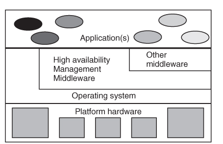
Under the initiative of a number of companies, comprised of hardware and software suppliers, an industry group called the high availability (HA) Forum (see Chapter 2) was formed to address the complexity of integrating COTS products to build highly available systems. They produced a document ‘Providing Open Architecture High Availability Solutions’ [21] which collected the best practices and capabilities needed for building highly available systems. It was intended as a guide to a common vocabulary and potentially applicable HA functions from which it was expected that the system designer would select the appropriate functions for each system based on the specific HA requirements, design complexity, and cost. The basic structure of the open HA architecture described in this document was used as a starting point for the SA Forum reference architecture. The architecture for a single constituent COTS system from [21] is depicted above in Figure 3.1.
Figure 3.1 Open HA individual system architecture.
The SA Forum took this initiative forward by developing a set of open standard application programming interface (API) specifications for the services needed to enable the delivery of highly available carrier-grade systems based on cost-effective COTS components. Wide adoption of these standard interfaces for HA middleware would enable reuse and portability, thereby reducing cost and effort for developers, system integrators, and operators. The specifications were shaped by group of highly talented and experienced system architects from major IT and network equipment manufacturers.
The goals and requirements that guided the process for creating the specifications are outlined in the next section.
3.1.2 Goals and Requirements
During the specification development process at the SA Forum a set of requirements and goals were used to assess the proposals made by various member companies and elaborate the final specification. These were derived from the business considerations and technical experience of the members. We describe these in some detail here to give insight into the background and motivation of the specifications. Among the architectural and business driven objectives the following considerations were borne in mind:
- Separation of hardware from software concepts to allow for the independent evolution of hardware, middleware, and application technologies and products.
- Providing a common set of abstractions for hardware and software resources for the purposes of HA management.
- Enabling the open integration of COTS components into a highly available system by factoring out common availability functions into a modular set of frameworks and services.
- Specifying interfaces rather than protocols to enable the development of common APIs that will protect application investment. It also allows for innovation and differentiation by middleware based on nonfunctional aspects such as performance, latency, and scalability. This also allows implementations to choose the protocols that best suit their particular application requirements.
A number of so called nonfunctional requirements were also taken into account. It was not feasible to directly assess the extent to which the proposals made by the various members for the candidate interface specifications complied with these requirements. The SA Forum relied on the implementation experience of the evaluation committees to make the appropriate judgments.
- Usability: Providing a simple programming model that covers a broad spectrum of systems and applications. Specifications should use a common consistent naming and programming style to facilitate learning and adoption. The interfaces should be described in directly usable programming interface for which there are established tools and integrated development environments.
- Portability: Dependencies on unique operating system or hardware specific features should be avoided and exposed system functions should be wrapped in abstractions that can be readily and efficiently mapped to different platforms.
- Upgradeability: Interfaces should be constructed such that they facilitate backward compatibility with newer releases of the specification.
- Deployment: Interfaces should be able to be implemented as one or more profiles representing subset-solutions for resource constrained platforms.
- Integration: Interfaces should be designed to facilitate integration with other interfaces and in particular with the configuration and management models.
- Performance: The nature of Service Availability Interface (SAI) specifications can to a certain extent influence performance trade-offs that need to be made when implementing and using the specification. For example, different replication styles impose varying trade-offs on central processing units (CPUs) and I/O overhead against fail-over and recovery times. Flexibility to use or configure low overhead operation variants, possibly with concomitant loss of functionality, is important for soft real-time systems such as communication controller network elements.
- Reliability: While not a property of interfaces per se; ensuring simplicity and clear functional separation between operations defined in the interface tends to lead to more robust implementations and applications.
- Scalability: As with performance there is a trade-off between imposing strong consistency semantics on the implementations and ensuring that systems will scale linearly and incrementally when adding resources, such as processors, memory, I/O interfaces, and nodes.
- Security: Interfaces should be designed to facilitate the application of the principle of least privilege policies in a system. This requires that separate functions are defined for operations requiring different privilege levels.
Whereas interoperability is important at mechanical and electrical interfaces as well as for low-level HW management (e.g., automatic bus enumeration, etc.) it was decided not to make it a fixed requirement to provide for interoperability of HA middleware services provided by different vendors on the same system.
Openness and choice of implementation technologies were identified as the key requirements which put the emphasis on defining interface specifications that could be implemented on a reasonably rich modern operating system with portability of the applications being the primary goal.
3.1.3 Service Availability Architecture Scope and Presentation
In working out the specifications, certain assumptions concerning the type of the systems being targeted had to be made. Before describing the conceptual model of the SA architecture we first describe the scope of the systems which the architecture is expected to address.
3.1.3.1 Scope
The architecture is intended to provide a structured view of the SA functions defined in the specifications, how they relate to each other and how they relate to the hardware and other software in the system. A system in this context is considered to be a configured set of hardware, software, and applications which are managed by or use SA functions. The system is further constrained by the following assumptions:
- The physical computational, networking, and storage resources of a system are assumed to be co-located in a single environment (such as a data-center or central office) under the control of a single operator. This implies that the physical security of all the resources is maintained by a single trusted organization. There can however be applications running on the system from more than one provider. Furthermore, no assumptions are made about the number of administrative entities managing their respective applications on the system.
- The computational resources are represented by a set of compute elements that are interconnected by a (possibly redundant) physical network in a logical mesh topology. A computing element is a unit comprised of a set of hardware resources capable of hosting or running applications and SA management software.
- Another implication of the co-location assumption is that the failure rates due to environmental conditions (e.g., air-conditioning or power failures), acts of nature, or vandalism are the same for all components of the system.
- The physical, software, and data resources of the system are assumed to be adequately protected against intrusion from external elements.
- Apart from the local or network storage required for compute elements to load their operating systems, middleware, and application software, no further assumptions are made on persistent storage.
The specified SA functions apply to the installation, operation, and upgrade lifecycle phases of the hardware, software, and applications that use them. While the architecture provides some guidance for system design phase, the development and test phases are currently not covered.
We note however, that implementations of the SA architecture and services could be built that perform adequately beyond this envisaged scope.
3.1.3.2 Architecture Description Approach
There is no common agreed definition of software architecture but for our purposes the following definition from Bass et al. [32] is appropriate:
The software architecture of a system is the structure or structures of the system, which comprise the software components, the externally visible properties of those components, and the relationships among them.
The SA Forum architecture itself is comprised of a comprehensive set of services that can be used in the construction of software systems capable of delivering the high levels of SA and continuity. Thus in our case the components of the architecture to be described are in fact the services provided to the applications as opposed to the functional components that constitute an actual final system. Also for reasons of modularity most of the services are fairly self-contained such that there is little or no coupling between them. The architecture is presented in terms of the common and unique attributes among the services on the one hand, and the relationships between the services and other elements of the system on the other. In our description of the architecture we will adopt some common views used in practice to describe software architectures:
- Interface abstraction—functional view;
- Operational model—dynamic view;
- Information model—static view;
- Use case view.
The published interface specifications of the various services define their externally visible properties which include their functional interfaces, information model, operational model, and administrative interface where appropriate. Some of the service specifications also provide use case views. In Section 3.3 we will look at the different services and how they relate to one another from a functional and dependency perspective. Brief details on the functional, operational, and information model view for each of the services as they relate to system and application availability are given. Part of the requirements for the specifications called for the cohabitation of the specified services with custom or legacy services within the scope of a SA system. For brevity and clarity we do not cover the interactions with these types of services here.
In the remainder of this section we make some general remarks concerning the first three views as regards the architecture and specifications.
3.1.3.3 Service Interface Abstraction Models
A compromise was sought between a high level of abstraction and a very implementation oriented specification. With a high level of abstraction broad applicability could be achieved but it was considered that this would leave too much room for interpretation in implementations which in turn would lead to divergence. An implementation detail oriented specification would need to make a choice between currently available technologies which would limit the addressable designs with the risk of not being future-proof. In order to satisfy the requirements for openness a number of interface abstraction models were eliminated:
- Fault-tolerant operating system abstraction;
- Protocol specific fault tolerance middleware (e.g., FT-CORBA (fault-tolerant common object request broker architecture) [33];
- Fault-tolerant programming languages or fault-tolerance extensions for programming languages.
The primary interface abstraction model adopted in the SAI specifications for the HA middleware is that of a concrete API specified in ANSI (American National Standards Institute) ‘C’ syntax that can be implemented and delivered as binary or source level interface libraries. A specification that describes the Java bindings for the interfaces has also been released. The specification for each service provides the signature and associated data-types for the functions provided by the service.
One of the consequences of the COTS hardware requirement is that the implementations of the specified HA middleware services should assume a ‘shared nothing’ platform model. This implies that the different elements of an HA service implementation can only communicate with one another via message passing. The SAI specifications only standardize the APIs leaving the design of the distributed algorithms and message formats to the implementers of the HA middleware services. Experience had shown that there is not a ‘one-size-fits-all’ distributed computing paradigm which led to the trade-off of sacrificing interoperability between different HA middleware implementations for application portability and system flexibility. In this context, to promote usability while meeting the scalability and reliability requirements, it was necessary that the interface specifications hide the distributed nature of the underlying platform from the service user. Since many functions would require the exchange of messages within the system, which would cause the function call to block for a duration proportional to the message latency and number of messages sent, many functions provide both synchronous and asynchronous invocation styles. Furthermore the programming model ensures that the application has complete control of the computing resources. When any HA middleware service needs to communicate with its user it is done via a callback mechanism. The programming model allows the application to fully control the dispatching of the callback invocations. Further details on the C/C++ programming model and the Java mappings are provided in Chapters 11 and 12 respectively.
3.1.3.4 Operational Model
Each service is specified to follow the same life-cycle in terms of initiating and terminating the service on behalf of a service user. Services also follow the same model for initiating and handling asynchronous operations as well as for tracking state changes in one or more of their defined entities. This uniformity in the programming model meets our usability requirement. Services also expose an internal operational model on the entities they define. These models are described in the specifications themselves. The complexity of the models varies significantly between the different services.
3.1.3.5 Information Model
There is no single encompassing information model for the architecture; rather the information model is the aggregation of the entities defined by the various services. As for the functional view this was driven by the need for modularity so that designers and implementers could adopt only those services of interest for their needs.
Let us now consider a SA system as consisting of a set of resources. Some of these are physical resources such as CPU boards, network interfaces and the like, others are software resources like operating systems and yet others could be system services that entities in the system can invoke such as network name to address translation. Depending on the set of HA middleware services configured in the system and their coverage in the system, a greater or smaller number of the resources of the system will be reflected in aggregated information model. Each HA middleware service represents the resources within its scope by the logical entities that are defined in its specification. Some of these entities can be acted on programmatically through the APIs of the respective services.
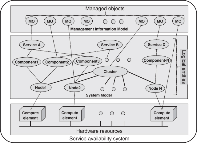
The services also expose some of their logical entities as managed objects in the management information model. Figure 3.2 illustrates how certain hardware and software resources are represented as logical entities in the system model and how some logical entities and resources are represented as managed objects in the management information model. This managed object model is managed by the Information Model Management service (IMM), which is intended to be used by all HA middleware services. Applications can also expose locally defined logical entities in the managed information model. These application defined entities may represent resources internal to the application or resources that are external to it, even resources that are external to the system. As part of the specifications the SA Forum provides the object definitions of all the managed objects defined by the various services as the ‘SA Forum Information Model’ file in XML Metadata Interchange (XMI) format [34]. Note that this only contains the managed logical entities of the different services exposing their configuration attributes, runtime attributes and administrative operations through the IMM.
Figure 3.2 Service availability system and information models.
In summary we may regard the architectural information model as the aggregation of the managed and unmanaged logical entities defined by the set of HA middleware services published in the specifications.
Chapter 4 further elaborates the SA Forum Information Model.
3.2 HA Concepts Applied
In the previous section we presented the scope of the architecture as a system with certain properties and constraints. We also described the overall structure of the architecture and how it is to be presented. Before examining the services and their interrelations we review the HA concepts that strongly influenced the specifications and how they can be applied on an abstract level.
3.2.1 To Be or Not to Be High Availability Aware
To deliver SA with cost effective COTS components requires the use of software fault tolerance techniques. For some high value transaction applications such as financial services or airline reservation systems the use of expensive hardware fault tolerant platforms may be appropriate. However hardware fault tolerance is not cost effective for modern internet information, communication and entertainment infrastructure systems where the total cost per transaction can only be a small fraction of a cent and is dropping. Nonetheless HW fault tolerant nodes may sometimes be used to provide certain critical functions such as system control in a largely COTS-based system.
In general systems based on software fault tolerance can only achieve the highest levels of SA with the active involvement of the applications. This is the so called HA aware application model. In this model some of the HA decisions are delegated to the application when a failure occurs allowing the application to continue to provide service albeit in degraded mode while recovery and repair actions are in progress. In contrast, in the HA unaware application model, the system can make no assumptions about what subset of resources and services an application needs to function correctly. As a result it will delay restarting or resuming the application until all the system level recovery actions have completed. This is typically the model that is employed in commercial HA clustering solutions. In order to achieve very high levels of SA all parts from the system must cooperate. For example:
- The hardware elements comprising the system must expose status and control interfaces for the system to be able to detect and react to changes in the availability and operability of the underlying resources.
- Applications need to cooperate with the SA middleware by signaling their ability to perform certain tasks while reacting to reconfiguration requests.
- All layers, that is, platform, middleware, and applications need to expose configuration and management interfaces to the operational support or IT management systems.
However, even when using software fault tolerance there is still the need for some level of hardware redundancy and excess system capacity to detect and recover from faults, tolerate hardware failures or reduce down time during system upgrades. The flexibility requirements on system scalability and reliability, that is, the ability to scale system capacity up and down as well as increasing or decreasing the availability level without restructuring the application software, leads to the need to support various redundancy models. These can range from having a back-up hardware element for each active element to having no back-up at all. In the latter case if an element fails the active software load is redistributed across the remaining elements potentially resulting in degraded service level if the remaining resources are insufficient to meet the total workload.
The function that is responsible for receiving the hardware and software failure notifications and redistributing the workload on the available and correctly functioning system resources is the availability management. It is in a way the core of the HA middleware.
3.2.1.1 Availability Management
Service Availability (SA) is ensured by the availability management functions at the platform, middleware, and application levels. In particular it is important for these functions to be able to cooperate and coordinate their actions. We will refer to the subset of functions in the HA middleware that are related to availability management as the availability management middleware (AMM). To ensure SA subject to varying scalability and reliability constraints over the lifetime of the system it was necessary that services be explicitly represented as entities in the system model of the AMM. One can think of an instance of a service that needs to be delivered by an application as job that needs to be done. Further, jobs are done by workers in a workplace and in our analogy workers are software resources and workplaces are hardware resources. In order for software to do its job it needs operational hardware to perform it on. So in a SA system we have a set of jobs to perform and a set of hardware and software resources to perform those jobs with. The aim of the AMM is to ensure that all the jobs are being performed properly as a function of the availability of the hardware and software resources. At a high level of abstraction software resources can be modeled as components. Components can be thought of as the workers that receive assignments for the jobs they need to perform by interacting with the AMM. In the system model a component is the basic unit of software from which applications are built. Essentially a component is comprised of a set of software functions that can be managed as a unit from the perspective of the AMM. In the design of our architecture a component is conceived as being instantiated by one or more processes (or tasks) executing on the same operating system on a hardware element with a single physical memory address space. Processes (or tasks) correspond to the basic software abstraction as provided in modern operating systems. The rationale for basing the component on process boundaries include the following:
- A process (or task) is the natural software unit that can be started and stopped by the operating system.
- Most current operating systems use hardware memory management functions to ensure isolation between processes by allocating a separate logical address space for each of them.
- A process can stop itself as a unit allowing well-written components that detect their internal errors to implement fail-stop semantics.
- The software of a process can also be replaced as a unit for upgrade or downgrade purposes.
We will call a hardware element that is capable of running an operating system a computing element to distinguish it from other hardware elements such as power supplies, and so on. Note that a computing element may host multiple operating systems concurrently as is the case with virtual machines. Thus from an architectural perspective we have three nested natural failure zones within a compute element:
To maintain SA in the event of a failure in one of the failure zones it is necessary to identify the set of components that are capable of taking over the jobs that were being performed by the failed component(s) (i.e., the worker(s) who are unable to continue to perform their jobs because they have died, become sick, or their workplace has disappeared). Note that if a computing element or OS goes down all the components housed by that computing element or OS are also considered as having failed.
Any form of automatic fault tolerant electronic data processing system must perform the following availability management functions:
- Fault handling
- Detect that a fault that has occurred;
- Identify the failed hardware or software element;
- Generate an error report to trigger recovery and repair;
- Contain or limit the propagation of the effects of the fault in the system.
- Recovery and repair
- Continue processing on the remaining healthy resources;
- Initiate repair operations on the faulty resources;
- Integrate repaired resources back into the system.
3.2.1.2 Fault Handling
With software-based fault tolerance systems some hardware and most software failures are detected by software monitoring and auditing. We also note in passing that the majority of failures in modern systems are in fact caused by software defects. In our system, hardware and software faults are monitored by various specialized HA services as described in Section 3.3. Note that whereas the AMM receives notifications of computing element, OS and process failures in the system from its internal monitoring functions, for HA-aware applications it relies on components to actively report any failures occurring within them that require its intervention.
3.2.1.3 Recovery and Repair
Some transient hardware faults are detected and corrected by the hardware, for example, error correcting memory. A component may also be able to recover from a failure occurring with its scope without the aid of the AMM. For example, when a process fails in a multi-process component the component may simply restart the failed process. When the AMM receives a failure notification in the form of an error report from a component, it will initiate recovery actions to maintain or restore the system functionality within the constraints of the available operational resources. Some of the recovery actions it has recourse to are the following:
- Restart the computing element on which the failure occurred;
- Restart the operating system in which the failure occurred;
- Restart the component in situ;
- Restart the component on a different OS/hardware element;
- Reassign the jobs of the failed components to other components;
- Restart the whole system.
As the granularity of the component, which is determined by the natural isolation boundaries provided by the operating systems, is fairly coarse we require the ability for a single component to be able to take on multiple jobs of the same or different types.
The flexibility afforded by the redundancy models and the ability of assigning single or multiple jobs to a component leads to a certain degree of complexity in the system model of the AMM. Despite this complexity it is still possible to accommodate simple single service HA unaware or basic active-standby HA-aware application models as well as the more sophisticated multi-service load balancing configurations.
3.2.2 HA Aware Application Perspective
For an application that is HA unaware it suffices that it be configured in the system model of the AMM. An HA-aware application, on the other hand, will have one or more components that will interact with the AMM. Here we will refer to the middleware service with which applications interact for availability management as the availability manager. Within the SA Forum system architecture it is called the Availability Management Framework (AMF) which is described in Chapter 6. Components are expected to detect faults within their scope, as mentioned above and to apply appropriate local recovery actions. If they require system level recovery actions to be taken they send an error report to the availability manager. A component may influence the choice of the recovery action that will be taken by accompanying the error report with a recommended recovery action to reduce service downtime.
The availability manager interacts with components by assigning jobs to or taking jobs away from them. Each job assigned to a component has a role associated with it which is determined by the availability manager. The role associated with a job tells the component whether it should play an active or standby role for that job. The way the availability manager maintains SA is by assigning and removing jobs from components and controlling the roles of the assigned jobs. For example, in the case where there is a corresponding standby job assigned for each failed active job, the availability manager performs a ‘fail-over’ by simply changing the roles of the standby jobs to active. The main responsibilities of the components with regard to the availability manager are to report detected errors and respond to the assignment of jobs and to changes in the role of their assigned jobs.
Some applications maintain an internal state that needs to be preserved between interactions with the external environment. In order to mask failures occurring in these applications some form of replication of their internal state across failure zones is required. Whereas hardware based fault tolerance systems transparently replicate all application state, in a software fault tolerant system it is up to the application or middleware to replicate sufficient state to be able to recover from a failure while incurring little or no loss in service. From a component perspective: If a component has an active job assigned, it must provide the associated service.
When a component has a standby job assigned, it must be ready to rapidly provide the associated service in the event that the availability manager sets the availability state of the job to active. In order to react swiftly to the change from standby to active availability state for one of its assigned jobs a component may require access to internal state from the component that was previously providing active service. To protect this internal state against the failure of a component or the node it is running on the state must be replicated to another component or node.
The methods used to replicate state between two or more components that are protecting the same job fall into two categories. The first is so called passive replication. In this case the critical state maintained by the component that has the active job is replicated or ‘check-pointed’ to an alternate location at regular intervals or when ‘significant’ state changes have occurred. The second category is the active replication method. With active replication each component sees the exact same sequence of service requests from the external environment where for the job assignments in the active state they generate outputs or responses to the external environment whereas for the standby job assignments they do not.
If the components (by design) start off with the exact same initial state with respect to the protected job under consideration, when a ‘fail-over’ does occur the component taking over the active state for the job will have an up-to-date copy of the application state. Active replication does, however, require that all choices in the execution streams of the participating components be deterministic to avoid the possibility that their copies of the state information diverge. Functions that support or provide active or passive replication mechanisms are generally provided as part of the HA high availability middleware of a software fault tolerant solution. Even so, in some cases components may resort to synchronizing their state using application specific mechanisms in order to take advantage of ‘piggy-backing’ replication data in application information flows.
While the availability manager consolidates the error reports from all HA-aware components it is often necessary for software components to reliably communicate with one another about changes in application or external state or synchronize access to resources. These features are also generally provided by the HA middleware to ensure consistent cluster semantics across the components and the availability manager.
In this section we have looked at HA high availability concepts and how they apply in the context of providing flexible levels of SA in a software fault tolerant environment. Before describing the different services in more detail we will introduce the architecture of the SA Forum Service Availability Interface Specification.
3.3 Architecture
3.3.1 Basic Architectural Model
As mentioned in the requirements of Section 3.1.2 a fundamental separation of concerns that needed to be respected was the decoupling of software management from hardware management to facilitate hardware evolution while protecting software investment. Accordingly two sets of specifications were produced: The Hardware Platform Interface (HPI) [35] and the AIS. This separation of concerns is based on the nature of the logical entities that are represented and manipulated in the interfaces. For the HPI the primary area of concern is to model hardware resources and to discover, monitor, and control them in a platform independent manner. The AIS focus is to facilitate the implementation and management of applications providing high levels of SA and continuity. Whereas the HPI functions are generally implemented in hardware or processors embedded in the hardware, the AIS services are implemented as middleware that typically runs on general purpose operating systems. The requirement for HPI implementations to operate in environments with limited processing and storage capabilities led to the difference in programming models adopted between the HPI and AIS. However, in order to provide a convenient, complete, and consistent programmatic view of both software and hardware in the AIS model a service dedicated to platform management was added to the AIS.
3.3.1.1 The Service Availability System
The SA system as it is exposed to an application is the set of computing resources across which the AIS services are available to it. In general terms it can be seen as a cluster of interconnected nodes on which the services and applications run. The nodes represent the actual computing resources which have corresponding entries in the configuration. Prior to virtualization being supported on general purpose COTS computing elements there was a convenient one-to-one correspondence between compute elements and nodes. Now however we need to make the distinction between a node as an operating system instance and a computing element as a single hardware element capable of hosting one or more than one operating system instance. In the SA system each node of a cluster corresponds to a single operating system instance running on a computing element.
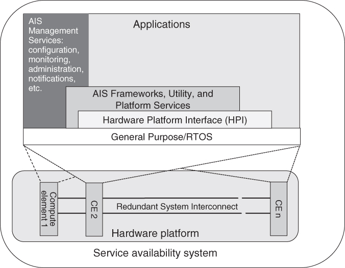
As shown in Figure 3.3 the computing elements in the system are attached to a possibly redundant system interconnect. The AIS software running on the nodes of the computing elements communicates over the system interconnect. From the platform perspective the system consists of the set of compute elements that have been specified in the platform configuration data. The AIS can use the HPI services to discover which of the computing elements are physically present and match them to its configured resources.
Figure 3.3 Service availability high level system architecture.
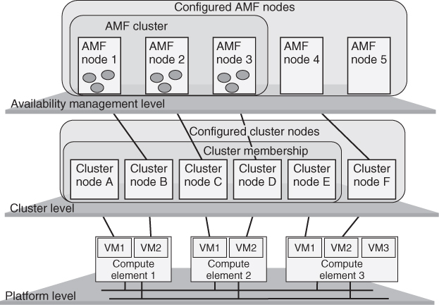
The HPI services operate independently of the configured system in that it may ‘see’ computing elements that are not part of the AIS system configuration. In typical implementations the HPI uses a separate out-of-band communication mechanism to discover and control the various hardware resources within its domains. Thus the topology and resource coverage of this out-of-band communication facility can be different from those of the system interconnect. There may also be separate communication paths to other computational, storage, and network resources that are not part of the computing elements or the system interconnect. In an ideal system all the hardware resources are discovered by the HPI and exposed in the management information model which identifies the set of configured computing elements present among them from the platform configuration data. The configuration data also specifies which operating systems should be loaded on the configured computing elements. Each operating system instance, referred to as a node, also has a unique node name assigned to it in the cluster configuration. The list of these node names in the cluster configuration data defines the system at the cluster level. At the highest level the availability manager configuration defines a set of nodes, some of which map onto cluster nodes. For applications managed by the availability manager the SA system is the set of these nodes that map to the healthy cluster nodes. In summary then the SA system exists at three levels: Platform level, Cluster level, and Availability management level. There is a one-to-one mapping of the availability management node to the cluster node and the cluster node to the platform operating system instance running on a compute element. For each level the configured system may differ from the actual physical system which may be different to the set of currently active and healthy nodes. The three level architecture of the SA system is depicted in Figure 3.4 below.
Figure 3.4 Service availability system architecture.
3.3.1.2 The Hardware Platform Interface (HPI)
The primary purpose of the HPI is to expose the monitoring and control functions of the hardware through a set of standard, platform independent APIs to applications, and SA management software. It includes functions to discover and access the inventory of hardware entities, sensors, and controls within the scope of the addressable hardware domain controllers. It also supports the fault handling, recovery, and repair mechanisms of the system through monitoring, control, and event management functions. The level of abstraction of the API provides ample room for hardware manufacturers to innovate and differentiate themselves by allowing certain fault handling, recovery, and repair actions to be performed automatically at the hardware platform level. For example, on failure of a fan the hardware controller might adjust the speeds of the remaining fans or resetting or power cycling a computing element via a watchdog timer.
Further details on HPI are discussed in Chapter 5.
3.3.1.3 The Application Interface Specification (AIS)
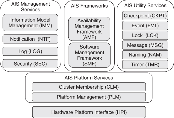
The AIS is split into a set of relatively independent services where each service covers a specific set of related functions. The service lifecycle of each AIS service used within an application is independent from that of the other services being used by the application. For convenience of presentation, related services are further categorized into four functional groups. We briefly present these functional groups before describing their constituent services in further detail.
- The AIS Platform Services are responsible for handling all the platform related functions and providing the necessary abstractions and controls for the other services. It is divided into two services:
- The Platform Management service (PLM) [36] which provides the abstractions of the hardware and low-level system software.
- The Cluster Membership service (CLM) [37] provides a cluster level abstraction of the system in terms of the current set operational nodes in the system. It supports the node level software availability management functions of other services and applications.
- The AIS Management Services group together the essential management services that are commonly required by software that provides management interfaces to external systems. In the SA Forum system these management services are the following:
- The IMM [38] which provides a consistent view of the configuration, administration, and management of all the hardware, software, and system resources that are exposed in the management information model.
- The Notification service (NTF) [39] hat provides a consistent way for applications and services to notify external entities about alarms and changes in the system. There is a separate error reporting mechanism used for the internal availability management of the system that is provided by the AMF.
- The Log service (LOG) [40] providing a system wide log management facility where alarms and other notifications including application specific notifications can be recorded and consulted.
- The Security Service (SEC) [41] which provides a means for the HPI and different AIS services to control access to their different functions from authenticated applications.
- The AIS Utility Services is a set of support services commonly used in distributed HA software applications.
- The Checkpoint service (CKPT) [42] provides a set of programming interfaces used by applications to replicate their state in the system to maintain service in the case of failures.
- The Event service (EVT) [43] is a publish-subscribe event distribution mechanism providing a many-to-many, anonymous, asynchronous communication facility.
- The Message service (MSG) [44] is a mailbox style distributed message passing facility.
- The Lock service (LCK) [45] is a distributed resource access coordination facility based on system wide lock objects.
- The Naming service (NAM) [46] is a simple distributed facility used for binding system object references to names and retrieving them by name.
- The Timer service (TMR) [47] is a node local facility for setting timers and receiving expiry events.
- The AIS Frameworks are special services that directly manage the applications and software configured in their system models.
- The AMF [48] provides the availability management functions to its configured applications.
- The Software Management Framework (SMF) [49] maintains SA during system or application software upgrades by coordinating the application of changes in the software configuration with the AMF.
The AMM we introduced in Section 3.2.2 maps to the group of availability management functions of the HPI, PLM, CLM, and AMF. A high level functional representation of the HPI and AIS service functional groups is provided in Figure 3.3. The functionality in each box depicted above the operating system exposes APIs to those above it and uses the APIs of those below. Each compute element in the system hosts one or more operating system instances. The software functionality depicted above the operating system layer is distributed across all the computing elements.
In this section we have introduced the various services constituting the HA middleware specified by the SA Forum. The functional grouping of the services is summarized in Figure 3.5.
Figure 3.5 Functional grouping of the HA middleware services.
3.3.2 The AIS Services and Frameworks Architecture
Now that we have defined the SA system and introduced the services we will briefly describe the roles and scope of the various AIS services and frameworks in providing SA support capabilities. In particular we will examine how their fault handling and recovery-repair functions interact with each other and the applications using them.
3.3.2.1 AIS Platform Services
The combined AIS Platform Services provide the interfaces and abstractions for the AMF to monitor and control platform resources. Applications and other availability management software running on the system can also avail itself of these interfaces to manage hardware resources attached to the computing elements that are not covered by the implementation of AIS platform service being used. These will typically be resources used to provide application specific services such as specialized digital signal processing capabilities in digital radio communications systems.
Platform Management Service
PLM provides a model in which to represent the desired configuration of the hardware and low level software (hypervisor and operating system) resources. It also provides a view of the actual hardware and low level software for monitoring and control purposes. In particular it exposes information on the presence, operational, and administrative states of the entities in the model. For example, the presence state indicates whether the configured resource is not-present, inactive, or active. When the presence state for a configured hardware resource becomes active it can be taken into account for availability management purposes. PLM allows service users to track this and other state changes affecting availability via its readiness status tracking APIs. For the purposes of this exposition we consider that the readiness state of a resource reflects whether the resource is able to function correctly or not. This notion is made more precise in the actual specification. When PLM detects that a resource has failed, its readiness state will be set to out-of-service and PLM will attempt to isolate the failed resource from the rest of the system to prevent the propagation of errored state. The PLM implementation may also be designed to attempt to automatically repair the failed resource. Should any of the AMM functions track the readiness state of the failed resource, when a successful repair action has been effected on it, they will be notified that the operational state has now transitioned to the in-service state.
Through administrative operations on a hardware resource or low-level software entity (e.g., an operating system or hypervisor) an administrator or manager application can shut them down or bring them back into service without regard to the actual implementation of the mechanisms used to perform the specific operations on the device or software entity. It also allows hardware and software resources modeled by PLM to be isolated from the system even if they are considered operational at the PLM level.
PLM also allows for the modeling of dependency relationships between the entities in its information model. This allows the reflected state of an entity be determined, in addition to the entity's own status, by the status of the other entities it depends on greatly simplifying the view that needs to be exposed to the PLM users.
The tracking interface provided by the service further simplifies the view for AMM functions and other users by allowing the tracking of groups of entities in a single request. The tracking interface also provides for fine grained coordination of managed operations. For example, let us suppose a blade computing element, currently actively providing service, is to be extracted for maintenance purposes. When the extraction lever of the blade is opened the HPI informs PLM of the intent to remove the blade. PLM will check whether the operation may proceed by asking its interested users such as the AMM to validate the operation. The AMM checks to see if there are sufficient resources to maintain service and if so it allows PLM to proceed with the operation. PLM now notifies users tracking this resource or the entities that depend on it, in particular the nodes or operating system running on it, that a termination operation has been started and waits for their responses. The AMF for its part receives its notification via CLM for each affected node and will accordingly migrate any active services off of the affected nodes by assigning the active jobs to components running on other blades. Once all the users have responded to the start of termination notification PLM terminates the entity and sends an operation completed notification to all tracking users. At the same time, when all software entities running on the blade have been terminated, PLM instructs the HPI to put the resource into the inactive state and sets the presence state to inactive. This toggles the state of a light-emitting diode (LED) on the blade informing the service technician that the board can now safely be extracted.
Reports of state changes of each of the entities in the PLM's information model are also sent to the AIS NTF where, depending on the configuration, they will also be logged. Operations support systems can automatically generate trouble tickets from these reports. The logs can be a valuable resource for operations, the system architect and reliability engineering staff.
3.3.2.2 Cluster Membership Service
The Cluster Membership service (CLM) is responsible for maintaining a consistent view of the set of currently operational nodes in the cluster. It uses PLM to track the state of the various hardware resources that need to be monitored to assess whether a node is functioning or able to function correctly. Depending on the implementation CLM may need to have recourse to other mechanisms such as node to node heartbeating over the system interconnect to determine the state of health of the configured nodes in the cluster. A healthy node must be able to provide all the services required of the node by the AIS services of the system as well as the application components configured to run on that node. In particular it must be able to communicate with the other nodes of the cluster.
The precise semantics of what constitutes a healthy node is not prescribed by the specification and is left up to the implementation. In a tightly coupled system a healthy node must be able to communicate with every other healthy node of the cluster. Effectively ensuring this tight semantics on a system with a large number of nodes can be very difficult. In another more loosely coupled model it may suffice for a node to be able to communicate with a small set of ‘controller’ nodes in order to be considered healthy.
One of the primary roles of CLM in the SA architecture is to notify the AIS services (and applications) using it of the addition and removal of nodes from the current set of operational nodes in the cluster. For example, when CLM informs the AMF that a new node has become operational, the AMF will start up the configured components on the node and assign the appropriate jobs to them and the role they should perform for these assigned jobs. As we saw from the board extraction example with the PLM in section ‘Platform Management Service’, CLM notifies the AMF not only of node removals but also of pending node removals, allowing the AMF to take the appropriate action before the removal actually takes place. When a node that is operational at the PLM level, is not considered healthy at the CLM level (possibly due to connectivity issues) CLM can use PLM functions to isolate and optionally repair the node by possibly rebooting it. In the SA system CLM is the ultimate authority about which nodes constitute the membership of healthy nodes in the system at any given time. The coherency of the AIS services in the system depends on the extent to which all services in the system rely on CLM for information on the membership of the healthy nodes.
In summary the Platform services provide fault detection, isolation, error notification, and repair on the entities within their domain of control in so far as these are handled by the implementation. PLM deals with hardware and low-level system software while CLM deals with the cluster and cluster nodes. CLM uses PLM for the fault handling and recovery functions but adds the necessary fault detection mechanisms in order to measure all the criteria needed for determining the state of health of a cluster node. Finally the Platform services provide interfaces for administrative management.
Chapter 5 presents the Platform services in more detail.
3.3.2.3 AIS Management Services
There are a number of common management functions that are needed in distributed systems providing highly available services. These common functions include configuration and runtime management; notifying applications, and external management systems of significant events occurring in the system; saving a record of significant events for further analysis; controlling access to critical system functionality. In this section we examine only how the AIS management services providing these functions contribute to maintaining the availability of services and applications. For more details see Chapter 8.
Information Model Management Service
In the AIS it is IMM that provides the interface for the configuration and runtime management functions of the manageable objects in the system. Each service in the AIS exposes their configuration and runtime information as well as their administrative interfaces through IMM. In the following we will describe examples of these functions as used by the AIS platform services.
As mentioned in Section 3.3.1.1 the SA system consists of the configured computing resources that correspond to the nodes of the cluster. This cluster configuration data is stored and managed by IMM. In the architectural model of the AIS the desired state of the system is described by the configuration and administration information held in the system management information model. Until now we have used the term system management information model to distinguish it from the logical information model which may contain programmatic entities that are not exposed in the management information model. The information model of IMM is the system management information model.
When the AIS services start they initialize themselves according to their configuration data. Once running they are notified of any changes to their configuration by IMM and are expected to apply the changes to the system. For example, the system configuration can have more computing elements configured than are actually physically present on the system interconnect. This allows the cluster to be scaled up to add capacity and/or redundancy by simply adding one or more physical computing elements that match the existing entries in IMM configuration. When one such computing element is added it is detected by HPI and reported to PLM which starts the configured operating system(s) on it. Once the operating system has started the node is detected by the cluster management service which adds it to the cluster membership and informs all interested parties which in turn then take the appropriate actions as determined by their configuration.
The condition where there are unconfigured physical compute elements on the cluster interconnect can also occur. These will only be taken into account if configuration data in the information model is added to reflect them. In the case of the cluster only those nodes having an entry in the cluster configuration data can become members of the cluster and therefore be used by the AIS services and the applications. To permanently remove a configured node (say) from the cluster it is simply removed from the configuration data. In order to remove its configuration data, the node would first have to be administratively locked and all references to the node in other parts of the information model would also have to be removed.
As we mentioned, when the configuration data for a particular entity is changed the service responsible for the entity will be informed by IMM of the change. In order to coordinate change of configuration that affects multiple entities, as in our example of removing a node's configuration, IMM provides a lightweight transaction mechanism whereby a set of related changes can be grouped into a configuration change bundle or CCB which will succeed or fail as a unit. If any operation or configuration change in the bundle is rejected none of the changes in the bundle is applied. This allows services to maintain availability by being able to enforce dependency or state change constraints that are not explicitly modeled in the information model where a sufficiently comprehensive implementation of IMM could take them into account.
IMM also plays a critical role in the case of a cold start or cluster restart in that it must provide for persistence of all the configuration data and persistent state of the system (such as the administrative state of the various entities). To protect the configuration against storage or other failures during system start-up before the other AIS services are available IMM must implement its own specific HA mechanisms. These might include replicating the configuration data onto different nonvolatile storage devices and being able to probe and test these devices to ensure the system has the latest valid configuration.
Notification Service
The AIS management service that provides the standard way for a service or application to notify other entities of significant events occurring in the system is the Notification service (NTF). The service defines various types of notifications specifically supported by the APIs including alarms, state change, security alarms, and object-lifecycle changes. Here we will examine how the general and alarm specific notification information contributes to the SA architecture. Further details on NTF can be found in Chapter 8.
NTF provides three interfaces corresponding to the role of the entity using them. These are the producer API for creating and sending notifications and the consumer APIs consisting of a subscriber API for receiving notifications as they are sent and the reader interface for retrieving stored notifications. In order to reduce the complexity of notification handlers, users of the consumer APIs can restrict the types of notifications they will receive or retrieve by applying filters on the values of some general and notification specific fields. For example, the general event type field for an alarm notification broadly classifies it according to the affected system area: communications, quality of service, software, hardware, or environment.
Other general fields include a timestamp, a cluster unique notification identifier, a reference to the object in the system information model emitting the notification as well as a reference to the object that caused the alarm. The unique notification identifier of one or more previous notifications may also appear in the general correlation field which together with the other fields mentioned allows the sequence of events relating to an alarm to be reconstructed for on-line fault management or reliability engineering purposes.
In addition to the general fields the alarm notification has a number of specific fields relating to the cause, perceived severity, trend, and proposed repair actions. Particular care should be taken in applications and services when setting the perceived severity field as the severity is often context dependent and can be interpreted by various consumers. Six perceived severity levels are provided for in the specification: alarm-cleared, undetermined, warning, minor, major, and critical. For alarms and security alarms the NTF implementation must as far as possible guarantee delivery as the availability of the system may depend on the notification reaching the appropriate fault handling function external to the AMM.
The architecture envisages that all AIS services and their user applications exclusively use NTF for alarm reporting to ensure consistent fault handling in the system. As the HPI is not an AIS service user it is up to PLM to produce HPI-related notifications. Within the AMM, for example, the AMF includes a separate error reporting function that allows components to inform the framework of errors to trigger recovery and repair actions; therefore no alarms are needed. The AMF produces NTF notifications based on the component error reports and sets the type and severity fields appropriately. This separate error reporting function provides for a tight coupling between the AMF and high-availability aware application components whereas the notification service's producers and consumers are loosely coupled and mostly independent of one another.
For consumers to reliably retrieve alarms even after a cluster restart NTF must ensure the persistence of alarm notifications.
In our architecture the NTF implementation is supposed to provide guaranteed delivery.
Log Service
The Log service (LOG) of the AIS provides a standard interface for writing log records and standard log record format rules which can be used to allow custom log analysis applications to be designed and implemented. Four types of log streams are defined: alarm log, notification log, system log, and application specific logs. The SA architecture envisions NTF as being the exclusive writer on the alarm and notification log streams.
From an availability management perspective LOG provides persistence for certain log streams and a log filtering mechanism to reduce the load LOG imposes on the system during high service load conditions. As part of the application specific log stream configuration data LOG provides a HA flag. When set LOG ensures that the log files associated with the log stream are persistent across cluster restarts.
LOG in and of itself is not critical to the functioning of the system and as such it should not unnecessarily consume system resources during times of overload. For operational, governance, business, or system engineering reasons some log records must be kept under all circumstances whereas other may be discarded without incurring severe consequences. To this end LOG defines a log filtering mechanism based on a log record severity attribute. Log record filtering applies only to the system log stream and application defined log streams because the alarm and notification log streams are considered to be essential in the context of the SA architecture. When writing a log record its log severity level can be set to one of seven values defined by the specification. In decreasing order of severity these are: emergency, alert, critical, error, warning, notice, and informational.
LOG provides an administrative interface to control the logging of records according to their log severity. Upon the onset of high load conditions a system-wide overload control facility can set the log filter on the log stream to block records with selected severities. When the load lightens previously filtered severities can be unblocked. At the time of writing there are no provisions for signaling specific load conditions in the AIS.
From an implementation perspective LOG must provide persistence of the highly available log files. LOG implementations should also specify how log file names in the configuration map to the node level path name of the valid copy of the associated log if node level replication is used.
Security Service
The Security service (SEC) is primarily concerned with preventing denial of service situations from occurring due to the excessive use of HPI or AIS services by unauthorized applications. Essentially it provides a framework for the authentication and authorization of it client service users. The enforcement of the authorization is delegated to the actual service in each case. The system designer must ensure that processes protecting a given service execute with same security privileges in order to avoid them being denied access to AIS services during a fail-over.
3.3.2.4 AIS Frameworks
What distinguishes the AIS frameworks from the other services is that they explicitly model application software artifacts in their system and management information models. For in depth introductions to these frameworks see Chapters 6 and 9. Here we will limit ourselves to discussing how these frameworks fit into the overall SA architecture.
Availability Management Framework
The AMF specifies the APIs that can be used by HA aware applications for them to actively participate in the fault handling and recovery actions of the system. The APIs allow the application components to be managed by the framework in accordance with the resources, services, and policies configured in the information model. Interactions between the AMF and the components of HA-aware applications follow the same model as the other AIS APIs, that is, AMF controls are received by components via callbacks. For a discussion of the AIS programming model see Chapter 11. HA unaware applications that are managed by the framework do not use the API but only appear in the AMF configuration.
As mentioned in Section 3.3.1.1 the AMF defines its own view of the system as a cluster of AMF configured nodes which map onto the CLM configured cluster nodes. This indirection or ‘late binding’ of AMF nodes to CLM nodes allows an AMF managed application to be configured independently from the clusters on which it will be deployed. The system model of the AMF defines a number of manageable entities to facilitate the configuration and administration of applications. Here we will limit ourselves to applications and the entities exposed at the AMF API, that is, components and jobs (which are formally called component service instances). Thus for our purposes we will consider that an application is composed of components and the jobs that those components are to perform.
The AMF application configuration specifies how the AMF should allocate the components to the AMF nodes and how to assign the jobs to those components. This includes the configuration of the redundancy relationship between components. Typically components are in a redundancy relationship if they can be assigned the same jobs in active and standby roles. The AMF defines a number of different redundancy models corresponding to the level of protection for the jobs that is to be provided by the components. In general higher levels of protection require higher levels of redundancy. The additional redundancy is manifested in the configuration by a greater number of components and AMF nodes.
When mapping AMF nodes to the CLM nodes in virtualized environments the administrator must ensure that the components in a redundancy relationship are not allocated to nodes that are hosted by the same computing element, if they are to protect their services against hardware failures. This can be verified programmatically by following the mappings from the AMF to CLM to PLM and then checking the PLM containment dependency relations in the PLM information model and its mapping to HPI entities.
The AMF manages fault detection for applications by relying on the CLM for node failure detection and implementation specific operating system mechanisms to detect the failure of the processes of the component that it knows about. It also relies on components to report component failures on themselves and on other components using an error report API. An HA-aware component reports faults it has detected to the AMF to trigger recovery and repair actions.
The AMF also provides a configuration and administrative command to start an external process to monitor the health of a component. This may entail having the external process send dummy service requests to the component or have it inspect information about the component. When the external process detects a problem with the component it also uses the error report API to notify the AMF.
An HA-aware component can also use the AMF health-check API to trigger periodic health checks and have the AMF monitor for solicited or unsolicited health-check responses. Should the component not respond within a configured time interval the AMF will assume the component has failed and take the appropriate recovery actions.
Components and their related administrative entities have a comprehensive set of states (e.g., administrative, operational, presence, etc.). Of particular interest with regard to availability management are the readiness and the HA states of the jobs assigned to a component. When the AMF has a job to assign, it evaluates the candidate components based on their readiness state. As we already mentioned, when the AMF assigns a job to a component it tells the component what role (or HA state) it should assume for that job, that is, active or standby. Thus a component has an HA state for each job assigned to it. The interpretation of this active or standby role is application specific in each case. AMF only coordinates the appropriate number of assignments in each role for each job.
The AMF also provides a job dependencies configuration parameter for each job. Unless all the jobs listed in the dependencies parameter of a particular job already have an active assignment the AMF will not attempt to assign that particular job to a component with the active HA state. In other words this is a way to inform that AMF that a given job can only be actively performed if the jobs it depends on are already being actively performed.
In this subsection we have briefly summarized the AMF in terms of the functions, states, and configuration only as they pertain to AMF nodes, applications, components, and jobs (aka component service instances) in order to provide the reader with a simple overview of its architecture. For further details the reader is referred to Chapter 6.
Software Management Framework
Modern software systems are continually evolving, whether it is to correct defects or to introduce new functionality on the software side or add, remove or replace resources on the hardware side. The purpose of the Software Management Framework (SMF) is to provide a well defined and ordered process to move the software and hardware configuration of a system from the current state to the new desired state while minimizing service impact. The sequence of changes and actions that describe how the system is to be moved to the new state is defined in a structured machine readable eXtensible Markup Language (XML) file called an upgrade campaign specification (UCS). The execution of such an UCS is managed through a state-model that the SMF maintains in the IMM.
The campaign is divided up into phases, procedures, and steps. As the campaign progresses through the steps it can roll-back to retry a failed step while not undoing all the work already done in previous steps. In the case of an unrecoverable situation it can roll-back all the executed steps, or when even that is not feasible fallback to the original configuration that was backed up in the initialization phase.
The upgrade campaign designer must take into account the dependency and compatibility constraints present in the system but that are not modeled in the system information model where the AMF automatically would take them into account. For example, when a component is being upgraded it may change the representation of the state information it replicates using CKPT. In this case the new component would not be compatible with the old component meaning that without application coordination just mechanically upgrading the components will not work if no outage can be tolerated. SMF exposes an API for such coordination.
The SMF relies on the AMF to maintain SA. It executes the upgrade campaign by applying CCBs to the IMM configuration of the AMF managed entities. It also performs the software installations and removals and interacts with AMF to lock/unlock, stop, and start the AMF entities. For details of the SMF the reader is referred to Chapter 9.
3.3.2.5 AIS Utility Services
These services cover the common functions typically required when developing highly available distributed applications.
Checkpoint Service
The Checkpoint service (CKPT) is designed to allow applications to replicate their state outside their address space of their components such that their state can be preserved across failures. In order to facilitate the implementation of highly efficient replication mechanisms no strong ordering requirements are imposed on consistency and the outcomes of concurrent updates to the same area of a checkpoint by different processes. On the other hand ordering of writes by a single writer must be preserved and inconsistencies signaled to the applications.
Redundancy is achieved by having multiple copies of a checkpoint on different nodes. A copy of a checkpoint maintained by the service is called a replica. The propagation of updates between replicas is determined at creation time by the application. At any one time there is a single active replica to which the updates are being applied with the updates being propagated to the remaining replicas by CKPT. If an application has chosen synchronous replication, write operations block until all replicas have been updated. In the case of asynchronous replication, write operations return as soon as the active replica has been written to while the propagation of updates to the other replicas occurs asynchronously.
Interestingly, CKPT has no configuration data in the system information model: the management of checkpoints and their replicas across the nodes of the cluster is handled automatically between the service and its users. Applications can control the number and placement of replicas by creating a so-called collocated checkpoint. A replica is created on each node on which an application opens a previously created collocated checkpoint. Collocated checkpoints can only be used with asynchronous replication. In order to ensure the highest performance for writing checkpoints the service provides a mechanism whereby an application can request the active replica be collocated with it. In this way when the AMF assigns a job in the active role to a component the component can set its local replica active to ensure that the state information needing to be replicated for the job can be written with low overhead while the service asynchronously propagates the information to the other replicas which were opened by the components that were assigned the same job in the standby role. If subsequently the AMF were to change the state of one of the standby assignments to active, when the component accordingly requests its local replica to be active the service will ensure that the replica is up-to-date before completing the request.
Although CKPT does not have any configuration data it does expose runtime information and statistics about checkpoints and their replicas through the IMM.
Chapter 7 takes a deeper look at CKPT.
Event Service
The Event service (EVT) is intended to provide a cluster wide event distribution service whereby applications can publish information to anonymous subscribers on named cluster wide event channels. EVT is typically used by application designers wishing to distribute state information between applications in a loosely coupled scalable manner.
As with CKPT, EVT does not define any configuration in the system information model. Event channels are created programmatically by the applications. An application may create or open an event channel taking on the role of publisher, subscriber, or both at once. Events are in fact just messages with a common header allowing subscribers to request the service to only forward those events to them that match their specific filter criteria on the header.
The specification calls for best effort and at most once delivery of published events to subscribers. Publishers set a priority level for each event sent. In the case of overflow due to resource limitations lower priority events may be lost. Should events be lost the service informs affected subscribers of the fact. Each subscriber sees events in published order within a given priority level and for a given publishing process. In other words the specification does not require strict global ordering with regard to multiple receivers and multiple senders.
In order to further reduce coupling between publishers and subscribers the service allows a retention time to be specified on events. This allows a subscriber that starts some time after an event has been published to still be able to receive it. EVT does expose runtime information about each event channel in the system information model. It includes information such as the number of subscribers, publishers, retained and lost events for each channel.
More details on the EVT can be found in Chapter 7.
Message Service
The Message service (MSG) was conceived to provide a flexible, cluster wide distributed message passing capability. The main use case is to facilitate the implementation of reliable scalable cluster internal client-server applications. Here typically the client in the cluster receives service requests from the external environment and distributes them to a set of servers. Additionally it was required that the service masks failures in a receiver from senders and to support load sharing between receivers.
In order to allow one receiver to take over from another receiver without the involvement of the sender the abstraction of a message queue or mailbox was introduced. A message queue acts as a buffer for messages sent to the queue where they are held until retrieved by the receiver. For example, assume we associate a single message queue, to which service requests are being sent, with a job that the AMF assigns to a pair of components. The job assignment for the first component is set to the active state and that of the other to standby. The first component, with the active state for the job, has opened the queue and is retrieving and processing the messages from the queue. In the meantime the second component simply waits for instructions from the AMF. Now assume that the first component suddenly crashes. When the AMF detects the failure of the first component it sets the state of the second component's job to active. The second component then opens the same queue and proceeds to receive and process the service requests from it. Any processes sending services requests to the queue will be unaware that there has been a failover. Any messages sent to the queue after the component crashed will have been buffered in the queue until received by the second component. Ensuring that sent messages are preserved in the face of random failures is a challenging task for MSG implementers.
The specification does not require that messages stored in message queues be preserved across node failures or cluster restarts. This allows message queues to be memory based for performance reasons. Sophisticated implementations may however provide protection against node failures without compromising performance. Various message sending models are specified: send and forget, notify sender on delivery to queue, and request-reply from the receiving process.
A message queue can have any number of processes sending messages to it but can only be opened by one process at a time for receiving messages. This avoids the complexity of having to implement a mechanism for notifying multiple processes for each message sent to the queue and providing ordering guarantees between them for receiving the messages.
In order to support load sharing the concept of message queue groups was defined. A message queue group has a name just like a single queue. Processes sending a message specify its destination by providing a name which can be either that of a single queue or that of a message queue group. The specification currently defines four load sharing policies for message queue groups of which round-robin is the only mandatory one. To optimize for latency an optional local round-robin policy is defined which behaves the same way as standard round-robin except that if there is a queue opened by a process that is co-located on the same node with the sender that queue will be preferred. A variant on this last policy is also defined which selects the local queue with the largest amount of available buffer space. These are all so called uni-cast policies in which a message sent to the group will only be delivered to a single member queue of the group.
The other policy is the broadcast or multi-cast policy which delivers messages that are sent to the group to each queue of the group that has sufficient room to buffer it. Again to simplify and ensure robust implementations atomic multicast semantics are not required.
MSG does not specify any configuration objects in the system information model but does expose detailed runtime information about queues and message queue groups.
Further discussion on the service is presented in Chapter 7.
Lock Service
The Lock service (LCK) specifies a mechanism to perform simple cluster wide distributed resource access coordination. The service defines an abstract entity called a lock resource which applications associate to actual resources in the system to which access by different components needs to be coordinated.
Both shared and exclusive locking of the lock resource are supported. Hierarchical or composite and recursive locks are not catered for at the time of writing. Any number of processes can have a resource locked in shared mode when no process has it locked exclusively. Only one process can have a resource locked exclusively at any one time. The principal use cases being multiple concurrent readers or a single process that can both read and write to the resource associated with the lock.
Locks held by a process are automatically released by the service if the process terminates or the node on which it is running leaves the cluster membership. The service specifies two optional features: dead-lock detection and orphaned locks. The orphaned locks feature allows the automatic releasing of locks by the service to be disabled in order to allow clean-up operations to be undertaken by other parts of the application. The application must explicitly purge the orphaned locks.
LCK maintains useful runtime information about lock resources in the system information model.
Naming Service
The Naming service (NAM) is intended to provide both node local and cluster wide name registry and look-up functions. Names are simple strings that can be bound to object references or other resource references which typically would include communication or service access point addresses.
The naming conventions used are a local matter for applications. In order to avoid namespace conflicts the service defines the notion of a context in which names are bound to references. Two contexts are defined by the service itself: a cluster wide context and a node local context. Applications can define their own contexts with cluster wide or node local scope. All contexts represent mutually disjoint namespaces irrespective of their scope. User created contexts with node local scope including the bindings they contain do not persist across departures of the local node from the cluster membership.
Apart from creating, looking-up, updating, and deleting name-reference bindings the specification also provides a mechanism for an application to monitor for binding creation, updates, and delete actions related to a name within a context. This can be used for an application to learn when a service becomes available or when it needs to rebind to a new service access point. For example, suppose an application needs to access some service called ‘S1’ on an interface that is determined dynamically at run time. The application will monitor for changes to the binding of the name ‘S1’ in the application's context by registering a call back function with NAM. Initially, when looking up the ‘S1’ it finds that no associated binding exists. When the interface is created and an address is assigned to it, a configuration management process binds the name ‘S1’ to an object reference representing the interface (possibly the distinguished name of a runtime object in the system information model). At this point NAM will invoke the call back function that was previously registered by the application to notify it of the new binding, obviating the need for the application to have to poll for changes or doing a subsequent lookup.
Another example is where a service endpoint is implemented as a socket interface with an Internet protocol (IP) address and port number as configuration parameters. When the job that provides service at that socket interface fails-over, the new active service endpoint may have a different IP address and port number. The process invoking services on the endpoint can be notified of the changed address by using the same monitoring technique as in the previous example. The component whose job end-point HA state is set to active updates the name binding. When this occurs, the service user is informed by NAM of the binding update and the service user connects to the new IP address and port number. This is in contrast to a failover of a service endpoint using a MSG queue instead of a socket address. Using the MSG queue avoids the need of the invoking process to be involved at all in the failover procedure.
NAM defines a configuration object class for the service defined default cluster wide and node local naming contexts in the system information model. This class allows the system administrator to set the configuration parameters of these contexts. It also exposes run-time information for them. A separate runtime object is exposed for each programmatically created naming context. The life-cycle of the configured default cluster wide and local naming contexts is coupled to the life-cycles of the cluster and the cluster nodes respectively. Applications, however, are responsible for removing any unused user created naming contexts and cleaning up all stale or unused bindings.
Timer Service
The Timer service (TMR) is a node local service specifies an operating system independent interface for common timer functions such as setting timers and receiving timer expiration notifications. TMR supports both single event (one-shot) and periodic (repetitive) timers. The expiry time can be specified as an absolute time or as a duration relative to the time at which the timer is started. Any timers started by a process are only visible and usable by that process. They are cancelled (i.e., destroyed) upon termination of the process.
Timers are a frequently used mechanism in HA applications to monitor for state changes or responses to service requests which need to occur within specific time bounds. Should the change or arrival of the response not occur within the time interval some recovery action such as retry or cleanup must be invoked. The specification does not require timers to survive process restarts or failures. A key design decision was to allow for implementations to support a very large number of timers per process. Very large numbers of operating system based system timers can generate considerable system overhead as it cannot make any assumptions about them. Implementations of the TMR must assume that the vast majority of timers will be cancelled before expiry requiring them to be extremely ‘lightweight.’ Timer values are specified with the standard time type which has a resolution of nanoseconds. However to promote portability and broad platform support for implementations the specification exceptionally imposes a nonfunctional requirement which is that the timer resolution should be no longer than 10 ms.
Unlike the other AIS utility services TMR is not a distributed service. It continues to provide service even on nodes that are removed from the cluster membership. One of the main reasons that TMR is not a distributed service is that it is complex and resource intensive to provide cluster wide scope for a large number of timer instances. Another is that it would require highly reliable fine grained time synchronization between the nodes in the cluster membership further exacerbating complexity and increasing the number of platform failure modes. The additional burden on applications to replicate timestamps of timer start times with their associated service requests and restarting them as part of application recovery action is relatively small. Note, however, that applications must also deal with the implications of time variations between different nodes on the cluster.
TMR has no administrative interface and exposes neither configuration data nor runtime information in the system information model.
3.3.3 Service Dependencies
As mentioned in Section 3.1.3.2 the different services were specified such that each interface is self contained with minimal coupling to other services. For example, the HPI and AIS specifications do not have any formal dependencies upon one another. In other words they can each be used separately or together. In the absence of an HPI implementation the PLM could be implemented directly on proprietary interfaces or another server system management standard such as Systems Management Architecture for Server Hardware (SMASH) [50]. A CLM implementation could even dispense with both HPI and PLM and simply use native operating system functions directly and perform the system network probing over the system interconnect to discover the set of operational nodes.
The SA architecture design does however impose two essential dependencies between the services: dependencies on CLM and dependencies on the AIS management services. In order to provide a coherent view of the scope of the operational system resources to applications all AIS distributed services depend on CLM. The two AIS services that do not depend on CLM are the PLM and TMR services. PLM was designed to facilitate the implementation of CLM. TMR is a node local only service as discussed in section ‘Timer Service’ and has no dependencies but all other AIS service could use TMR.
The dependency of all AIS services except TMR on the AIS management services is intended to provide a common administrative view on all services. This includes management of configuration and runtime information, administrative interfaces, notification and logging of system events and changes.
In the preceding presentation of the various services we have already discussed some of the interactions they have with other services. Figure 3.6 depicts the ideal dependency relations between the various services as envisaged in the SA architecture from a service implementation perspective. These dependency relations are not normative and may vary in actual implementations.
Figure 3.6 Ideal dependency relationships between services.

Here we limit ourselves to summarize the ideal and assumed dependency relationships.
The PLM was designed to work with HPI and to provide the bridge between HPI and AIS. The relationships of AMF depending on CLM depending on PLM for availability management were illustrated in Section 3.3.2.1. Although there are no direct dependencies of other services on the AMF, service implementers can choose to model the service implementation as an AMF application. The SMF clearly relies on the AMF in order to manage its activation and de-activation units (for details please see Chapter 9). However, it does not directly interact with the AMF by calling the AMF APIs. It drives the AMF by applying changes to the AMF managed entities in the IMM and using the administration interface of the AMF.
The AIS Frameworks, Platform services, and all the Utility services except for TMR depend on IMM and NTF for management and administration purposes where appropriate.
All distributed services except PLM depend on CLM which depends on the AIS Management services. Thus there is a mutual dependency between CLM and the Management services. Resolving the mutual dependency between CLM and IMM during system start-up requires special care on the part of the service implementers.
NTF ideally depends on LOG for persisting alarm and notification events and LOG depends on NTF for sending alarms and log stream life-cycle and change notifications. All services that send alarms or notifications indirectly depend on the LOG. For simplicity in the diagram of Figure 3.6 we thus group LOG and NTF together.
Note that IMM depends on NTF for sending miscellaneous notifications and NTF depends on IMM for its filter configuration settings. The use of the SEC for some of the AIS services has not yet been defined but it is planned for all services to use SEC. SEC for its part does not have a direct dependency on NTF as its service users are expected to send notifications and security alarms as part of their authorization procedures.
In addition implementations may use one or more of the AIS utility services in the implementation of other services. For example, TMR can be used in most other services. MSG can be used by the AIS management services and the other utility services.
3.4 Open Issues
Over the past decade much has transpired in the industry and much experience has been gained by the SA Forum members and the ecosystem of implementers and adopters of the specifications. In this section we will look at some of the open issues that have emerged over time and some additional services that still remain on the drawing board.
3.4.1 The Optional Features Issue
The definition of optional features such as the nonmandatory load-sharing policies in the MSG or support for orphaned locks and deadlock detection in the LOG is at variance with our primary goal of application portability. Applications making use of the optional features may not be portable to other AIS implementations. It thus becomes a difficult trade-off between the advantages realized by the optional feature or features relative to the benefits of portability. Often the underlying reason for making a feature optional in the specification is that the implementation may be particularly onerous or that the feature may compromise certain nonfunctional characteristics of the service. We should add that backward compatibility rules for the specifications allow new features to be added without affecting existing applications. In retrospect then it may be preferable to avoid optional features altogether. New features can then be introduced after it has been ascertained that they are useful and able to be implemented efficiently while not compromising other desirable nonfunctional service characteristics.
3.4.2 Integrated AIS Service API
The second open issue is a consequence of the conscious decision to try and ensure that each service could be implemented in a self-contained manner. This decision was motivated by the business need for software companies to be able choose to implement only that subset of the interfaces they were interested in and for which they had sufficient development resources without depending on services provided by other suppliers. As a result each service has its own independent life-cycle as seen from the application perspective. While the consistency of the life-cycle and programming model required by the architecture of the AIS services simplifies the use of many different services in an application, it still creates a substantial housekeeping burden on the application to maintain the separate handles and contexts of the different services. Thus there is the temptation for a project that will be using many of the services in its programs is to wrap the life-cycle, selection and dispatch routines of the different services into a single common proprietary library, which is then used across the project. Now that high-quality, open-source implementations of most of the services exist there is no longer a pressing need for independent services. Thus in retrospect it might have been better to define a single life-cycle and interaction API framework into which the services could have been plugged.
3.4.3 Common Low Level Communication Facility Interface
The third issue is also related to the integration of independent services. When integrating different AIS services, that have been implemented by separate independent suppliers into a single coherent system there is the inevitable issue that there will be duplicated low level functions. In particular all distributed services require some form of underlying cluster wide communication facility. Whereas some services can use the MSG in their implementation, others cannot. The duplicate implementations may have different behaviors when encountering a common fault affecting both facilities. Furthermore when isolating a node during fault handling, multiple communication facilities need to be notified and participate in the isolation. Of particular concern is the issue when the reachable set of nodes is different over the various facilities. In short the duplication of communication facilities entails increased configuration complexity as well as testing burden for the integrator. A common low-level communication abstraction interface specification with well-defined semantics for use by all service implementations would greatly facilitate the integration task.
3.4.4 Common Distributed Process Management Interface
Another missing common function needed by all service implementations is that of distributed process (or task) management. While it was a stated objective to remain operating system neutral it would nonetheless have been possible to define an abstract process management service that would support the instantiation, monitoring, and termination of processes in the cluster. Users of this service could include the AMF, service implementations not managed by the AMF and multi-process components.
3.4.5 System Trace Service
LOG is designed to maintain a record of system and application related events in support of the system operator and application service provider. Distributed systems are notoriously difficult to test and debug and there is a need to record runtime system implementation related information in support of the developer and system integrator. The difference in requirements between tracing and logging is sufficiently great to warrant a separate service. Firstly the nature of the information recorded should allow the identification of the functional area in the source code emitting the trace record. The service must be extremely efficient since it must support very high rates of trace message recording in live systems without affecting service levels. Furthermore it should support the selective enabling of global trace levels and tracing of specific functional areas without requiring specific explicit trace configuration data for each process in the system information model. Finally it requires relatively fine grained cluster-wide consistent time stamps to enable post hoc failure cause analysis across a set of node local trace logs. This service has not yet been specified.
3.4.6 Diagnostics Framework
Another service that has been on the drawing board for some time is the diagnostics framework. As part of the repair procedures following a failure it is often desirable to test the potentially still faulty or repaired component in situ without its administrative or operational state changes being taken into account by the AMF. Similarly it should be possible to schedule routine diagnostics on different parts of the system and have the results in a standard format to facilitate automated analysis.
3.4.7 Overload Control Framework
Although disastrous total system failures are relatively rare, when they do occur, most often the cause is inadequate overload control. While there are some discrete mechanisms defined such as the HA readiness state for service assignments, node, and service capacities in the AMF, log levels or message and event priorities that can be used to limit the use of resources when overload conditions occur there are as yet no consolidated runtime usage states and throttling mechanisms defined in the specifications to signal and control overload conditions. The runtime state might include usage states for cluster resources and component job assignments. Controls may take the form of service priorities and service request admission rate policies. Like security, one of the challenges with specifying overload detection, prevention, and control services is that they affect most of the existing specifications. Making the changes to accommodate overload control represents a considerable effort requiring great care to maintain backward compatibility. Service related resource usage information for an overload control framework could also be used to define additional load-sharing mechanisms in MSG. Adding this feature may be a first step toward a full overload control framework.
3.5 Conclusion
In this chapter we have presented the SA architecture with its constituent services. We began by giving some background on the specification creation process and presenting the architecture description approach. We then reviewed some basic HA concepts and outlined how they are applied in software based fault tolerant systems. In the presentation of the architecture and its services we examined the interactions between the services that illustrate how they work together to provide high levels of SA and continuity. Throughout we have tried to describe the design considerations and trade-offs that were made in selecting the functionality that was included in the specification. Designing and implementing reliable, flexible, and high performance distributed systems is a complex and difficult task. The choices of features and functionality in the specifications were strongly influenced by the many lessons learned in previous proprietary systems. It is hoped that this exposition will help the reader to obtain a better understanding of the specifications and to encourage the brave to tackle some of the remaining open issues.