
Chapter 5
Consistent and High Level Platform View
5.1 Introduction
The first prerequisite necessary for managing service availability (SA) is reliable information about all the resources available in the system that can be used to maintain the availability of the services offered by the system. The goal of the platform services is to provide the availability management with this information about the platform, that is, about the execution environments (EEs)—encompassing the SA Forum middleware itself—that can be used to run applications that deliver the services in question. In the process of providing this information the platform services also manage the resources at each level and even expose some of the control functionality to their users.
The SA Forum system architecture splits this task into three parts:
The Hardware Platform Interface (or HPI) [35] deals with monitoring and controlling the hardware resources themselves. The approach is that hardware components are given; these resources cannot be modified from within the system. Appropriately HPI has a discovery mechanism to find out exactly what hardware components are present, in what state they are and what management capabilities they have. It exposes these components and their capabilities in an implementation independent way so HPI users can monitor and control them as necessary for their purposes. HPI also provides timely updates on changes that happen to the system or to its components regardless of whether these changes are the result of internal events such as failures, programmatic management operations from users such as resetting a resource; or external (physical) interventions such as the insertion or removal of a blade in a server blade system. The HPI makes accessible the manageable capabilities of hardware resources such as fan speeds, sensor thresholds, but it also offers interfaces to control firmware upgrades and to initiate diagnostics.
The Platform Management service (PLM) [36] uses the information provided through the HPI. The main task of the PLM is to map the hardware discovered by the HPI into the PLM configuration which is part of the system information model. The configuration indicates the expected entities and their particular locations within the system. PLM then compares this information with the discovered hardware entities. If there is a match, it allows the entity to become part of the PLM domain and to boot the EE together with the SA Forum middleware as appropriate. The PLM information model also reflects the virtualization facilities such as hypervisors with their hosted virtual machines (VMs) potentially each providing an operating system (OS) instance as an EE for applications.
The PLM monitors and performs some basic life-cycle management of these entities primarily for the purpose of fault isolation. It also exposes to its users the up-to-date status information on the entities within its domain and some management capabilities on them.
Once the inventory of the hardware elements (HEs) and the EEs running on them has been established, the Cluster Membership service (CLM) [37] forms a cluster. Each PLM EE may host a CLM node and the cluster may include only the nodes configured for the membership.
Based on the information received from PLM about the PLM entities, the CLM is in charge to decide whether a configured node residing in a given EE is indeed healthy and the node is reachable so that distributed applications can use the node as part of the cluster. The CLM guarantees the formation and maintenance of a single cluster and up-to-date and reliable membership information. All Application Interface Specification (AIS) services with cluster-wide services rely on this information for their decisions on their resource handling to best support SA.
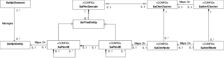
The platform services form a stack, one layer using the services of the other in a well-defined way for a well-defined purpose. However their interfaces are not exclusive to AIS services. Any application requiring up-to-date platform information may link the appropriate interface and obtain the information from any of these services directly. Figure 5.1 shows the mapping between the entities of the different layers of the Platform services.
Figure 5.1 Mapping of entities of the different layers of the platform services [62].
In the rest of this chapter we take a closer look at each of these services and the way they work together to enable SA.
5.2 Hardware Platform Interface
5.2.1 Background
Relying on a feature rich hardware platform is essential for availability management. This feature richness includes the capability to detect hardware, monitor, and control its state. Since the availability management is a software solution it is desirable that these functions are offered through a programming interface.
The development of the HPI specification was the result of the growing trend of building hardware platforms modularly as a loosely coupled set of compute and I/O blades. These platforms required a centralized management and a common interface that could be used by the availability management.
Several vendors started the development of their own proprietary solutions. At the same time the PCI Industrial Computer Manufacturers Group (PICMG) initiated the development of the CompactPCI [65] and later the AdvancedTCA [66] then MircoTCA [67] specifications, all of which for management relied on the Intelligent Platform Management Interface (IPMI) [68].
The IPMI effort was led by Intel who also initiated the work on a complementary hardware platform management application programming interface (API) named the Universal Chassis Management Interface (UCMI). It addressed the gaps identified by the High Availability Forum, an industry group discussing the issues of open architecture based high-availability computer systems.
From its formation the SA Forum drew on the heritage of the High Availability Forum, and the UCMI initiative became the core part of the first release of SA Forum HPI specification.
While exposing all the richness of the underlying technology HPI defines a platform independent management API that the high-availability middleware and applications can use to monitor and control the platform hardware in a uniform way.
HPI is designed to be flexible and to provide management capability for any type of hardware and not only blade systems typically used for high-availability systems. Its key feature of discovering the hardware topology and the management capabilities first allows for the creation of management applications without advance knowledge of the targeted hardware.
Since its first release, the SA Forum has published several updates to the HPI specification. It was complemented with specifications standardizing the access of an HPI implementation via Simple Network Management Protocol (SNMP) [69] and also with the mapping between HPI and xTCA compliant platforms [70].
5.2.2 Overview of the Hardware Platform Interface
The HPI specification defines a set of functions that allows applications and the middleware to access the management capabilities of the underlying hardware platform in a platform independent and uniform way. The specification defines a model that guides the access to these management capabilities. The basic concepts of the model are: the HPI entity, the management instrument, the resource, the session, and the domain.
HPI entities are the hardware components in the system that compose the hardware platform ranging from fans to compute blades and processors. HPI entities reflect the physical organization of the platform and accordingly HPI entities are identified based on their location information tagged with their type.
HPI entities expose different management capabilities allowing one to determine and/or control their status such as reading their temperature or performing a power cycle. These different management capabilities are modeled as management instruments.
There are different types of management instruments: as simple as a sensor or a timer, or as complex as a firmware upgrade management instrument (FUMI) or diagnostics initiator management instrument (DIMI). The HPI specification classifies them and for each class defines an appropriate set of functions that manages the particular aspect of the hardware components they represent.
For example, the sensor management instruments provide readings for different measurements regardless what is being read. The sensor type returned as part of the reading determines the interpretation of the values read. Besides reading sensor values HPI allows one to define and adjust thresholds on them so that when violated HPI generates events—essentially alarms. In turn management applications can react to them potentially using other management instruments associated with the same HPI entity to resolve the situation. For example, if the temperature is too high the user may use an available control management instrument to turn on a fan.
It is important to see that the management instrument physically does not have to be part of the associated HPI entity. For example, if the HPI entity we would like to control is this fan in the chassis and the triggering event to turn it on or raise its speed is a rise in temperature above a given threshold, the temperature sensor generating this triggering event is not likely to be part of the fan itself. It might be located at the farthest place that this fan needs to cool.
The control and the sensor used together to control this fan would compose an HPI resource, that is, a set of management instruments which are used together to manage some HPI entity representing some platform hardware. HPI resources reflect the logical organization of the system for some management purposes.
The management application gains access to the different HPI resources by opening a session on an HPI domain. The domain groups together a set of resources and the services necessary to discover these resources as well as additional domains. Furthermore, it provides event and alarm management and event logging services.
Accordingly, an HPI user is expected to discover the management capabilities available on the HPI implementation it is connected to. A possible starting point for this is the ‘default domain,’ which is a concept supported by all HPI implementations. From this and using the domain services the HPI user can discover the different resources available in the domain and any additional domains it can further explore. Different HPI implementations may interpret the ‘default domain’ concept differently. For example, one may associate it with one particular domain within the platform, while another implementation may associate it with a different domain for each subsequent user request.
For each of the resources in the domain the HPI user can find out the following information: The entity the resource is associated with including its inventory data; the management capabilities the resource itself exposes for the entity (e.g., whether the entity is a field replaceable unit (FRU) that supports hot-swap); and any additional management instruments included for the resource (e.g., sensors, controls, FUMI, DIMI, etc.) in the domain.
Although it is typical, resources are not in an exclusive relationship with their associated entities. They may represent only a certain management aspect of that entity, while another resource may expose additional aspects. For example, if the earlier-mentioned fan is hot-swappable the hot-swap capability may be exposed through a different resource which reflects all the features impacted through the hot-swap.
Once the HPI user has discovered the current platform configuration it may subscribe to the events generated in the domain it has a session with. Among others these include notifications about changes in the domain configuration, that is, the HPI implementation indicates when resources are added to or removed from the domain. There is no need for periodic rediscovery of the platform.
The HPI specification does not cover any details on how the HPI implementation itself collects the information exposed through the API or how the hardware entities and the related model concepts are configured, for example, what features of an entity are exposed through a particular resource. All this is left implementation and therefore vendor specific.
The HPI specification also does not mandate any synchronization among different instances of HPI implementations. For example, if implementations of different vendors are combined into a system, they will coexist without any knowledge of each other—at least with respect to their standard capabilities. Any coordination between them is beyond the scope of the current HPI specification.
In the following section we elaborate further each of the mentioned HPI model concepts starting with the HPI domain.
5.2.3 The HPI Model
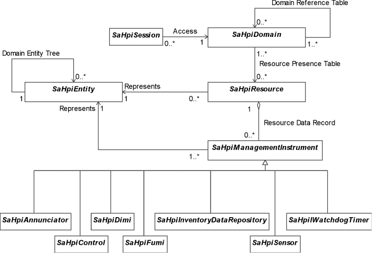
Figure 5.2 presents an overall view of the HPI model concepts that we elaborate on in this section.
Figure 5.2 HPI model elements and their relations.
5.2.3.1 HPI Domain and Session
As we have already seen, an HPI domain exposes a set of services common to the domain, which are collectively referred to as the domain controller as they cover administration aspects; and a collection of HPI resources accessible through the domain.
Although the wording ‘collection of resources’ could suggest that the HPI domain is a set of physical entities, it is more appropriate to think of the domain as an access control mechanism, or even filtering mechanism. The same resources may be accessible through several domains while others may be dedicated to a particular one.
An HPI user initiates the access to a domain by opening a session on the domain. The user will see only the resources of this domain and it can access only these resources within the given session.
The domain controller includes two tables: the resource presence table (RPT) and the domain reference table (DRT). The former allows the HPI user to discover the domain itself while the latter can be used to discover other domains in the system.
Domains may be related to each other depending on what can be discovered from these tables:
Peer domains are domains that allow access to a single set of resources and discover a single set of domains. That is,
- the RPT of each domain in the peer relationship lists exactly the same set of resources; and
- the DRT of each peer domain references all the other peer domains and the same set of nonpeer domains.
For example, assuming domains X, Y, Z, and W in an HPI implementation; domains X, Y, and Z are peers if they all list in their respective RPT the same set of resources {a, b, c, d} exclusively. In their DRT X has {Y, Z, W}, Y has {X, Z, W}, and Z has {X, Y, W}. W is a nonpeer domain that can be discovered from any of these peer domains.
Essentially peer domains provide redundancy of the domain controller functionality for a given set of resources.
There are subtleties, however, that HPI users need to be aware of:
Initially, the HPI implementation will populate the RPT of each of the peer domains X, Y, and Z with exactly the same information with respect to the set of resources {a, b, c, d}. The HPI users of each of the domains may manipulate this information, and they may manipulate it differently. For example, users may tag the resources differently in the different domains. It is like ‘personalizing the browser’ through which they see the domain. The HPI implementation does not synchronize such changes across peer domains; only users of the same domain will see the same information for a given resource, that is, all users of the domain use the same ‘browser.’
Subsequently, as changes happen in the system—some resources may go away, others may appear, the configuration, the state of the controlled hardware may change—the HPI implementation will update the RPTs of all the domains and peer domains will continue to see the same set of resources. However there may be some differences in the timing and the order as if the browsers of the peers domains show the same scenery, but from different angles.
Domains may also be in a related nonpeer domain relation as we have shown W in our example. These are those domains that can be discovered by an HPI user who initially had only a single entry point to the set of related domains. Related nonpeer domains also have disjoint sets of resources, which guarantees that the same resource will not be discovered twice, through two different domains except if these are peer domains, in which case the entire domain does not need to be discovered the second time. Related nonpeer domains compose a loopless tree structure in which there is only a single path leading from one related domain to another.
One may interpret related nonpeer domains as different management aspects of the system. For example, one domain may collect all the resources providing temperature control capabilities for the system, while another would allow hot-swap management only. These related nonpeer domains may be complemented by a set of peer domains that expose the same set of sensors so that any of the managers using the nonpeer domains can observe how the system state changes as a result of the interactions.
Finally domains that do not fall into either of these categories are called unrelated domains. Unrelated domains have no restrictions on what resources may be accessed through them. Typically an HPI user needs to have advance knowledge of an unrelated domain as by definition it cannot be discovered through the discovery process and therefore their use is discouraged by the specification.
Note also that this means that domains accessing overlapping but not equal sets of resources cannot be related through the DRT. They need to be unrelated. So if we want our temperature and hot-swap control managers to access each their own single domain we can only use unrelated domains as they would need to share the access to the overlapping set of sensor resources while also accessing the appropriate control resources.
HPI users may open multiple simultaneous sessions to the same or different domains. Also a domain may be accessed through multiple sessions simultaneously. However HPI does not control concurrency. User may detect concurrent changes by checking the respective update counters maintained by an HPI implementation as well as by listening to the events it generates.
Besides the RPT and the DRT, the domain controller maintains a single event channel specific to the domain. Events published on the channel usually indicate some kind of change within the domain or within the HPI resources accessible through the domain. This event channel is a very simple interpretation of the publish/subscribe paradigm.
The publishers of the domain event channel are: the domain controller itself, the resources accessible through the domains, and HPI users with open sessions to the domain.
To receive the events published on the channel, an HPI user needs to subscribe with its session id. Once done so it will receive all events published in the domain. That is, no filtering capability is provided by the HPI event manager; hence all subscribers of the domain will receive all events published on the domain's event channel.
Logically the subscription results in the creation of an event queue dedicated to the particular subscriber. The HPI implementation places a copy of an event to each of these queues. The copy remains in the queue until the consumer HPI user retrieves it. To read the events a subscribing HPI user needs to call the get API function, which returns the first available event in the queue. This call can be invoked in blocking mode so that events are delivered as they occur.
If it is a resource that generates an event, the same event will be published in all domains through which the resource is accessible. If more than one such events is generated simultaneously in the system, the order of their publication may be different in each of the domains that the generating resources are visible from.
One of the subscribers to the domain event channel is the domain event log. As one may expect, it collects the events occurred in the domain, however, there is no requirement on logging all the events. Each HPI implementation may implement its own filtering criteria. The HPI provides no API to set or modify these criteria.
Finally the domain controller maintains a third table, the domain alarm table (DAT). Alarms indicate detected error conditions in the system.
When an error is detected within the domain or in a resource accessible through the domain an entry is added to the DAT. The entry remains in the table as long as the error condition persists unless it is a user generated alarm, in which case the HPI user can remove the entry. System generated alarms can only be cleared by the HPI implementation. Their entry is removed from the DAT when the HPI implementation can no longer detect the related error condition.
The HPI specification does not mandate any method for announcing the presence of an alarm in the domain. An HPI implementation may choose its own mechanism, for example, it may light an LED or use an annunciator management instrument, which then generates an event that users subscribing to the event channel may receive in real-time.
5.2.3.2 HPI Entity
The actual hardware components managed through a domain and its resources are reflected in the HPI model by HPI entities. These are the hardware platform components capable of providing some services like housing other entities or cooling them; and carrying out some jobs such as running an OS instance or storing information.
HPI entities do not have an identity outside of the system; they have only types such as being a power supply, a cooling device, a central processing unit (CPU) blade, or a chassis. When an entity is inserted into the system it becomes uniquely identifiable for the HPI implementation based on the location it has been inserted. Accordingly, HPI entities are identified by a construct called the entity path.
The entity path is the sequence of {entity type, (relative) entity location} pairs starting from the entity and toward the system root. An example of an entity path is the following: {{power supply, 2}{subrack, 3}{rack, 1}{root, 0}}. The location numbering starts with zero, so this entity path identifies the third power supply in the fourth subrack of the second rack within the system.
The structure of the entity path implies that the HPI entities are organized into a tree—the domain entity tree (DET). This tree structure serves like a map for the HPI implementation. It knows the way it is built and therefore all the locations on the map that may house entities of different kind. When the entity is inserted, the type and the location information create its identity specific for the system into which it was inserted.
This tree organization allows for some flexibility, that is, the HPI implementation does not need to know the entire tree structure from the beginning; the tree can be extended at real-time with sub-trees for entities that nest smaller entities. The numbering of peer nodes within the tree, that is, the locations on the map is implementation specific. The specification does not mandate such details as whether it is left-to-right or right-to-left, and so on.
The tree organization also implies that when a node goes away, all its children go away too: For example, when a carrier blade is removed from the system all its mezzanine cards go away with it.
The entity path is unique within the system and it reflects the physical location of an entity regardless how it is obtained through which domain. The HPI implementations must guarantee this. In other words, all resources managing an entity should be able to use the same entity path, even if they access it via different domains.
For maintaining SA, it is essential to know the status of the different HPI entities at any moment in time and to be able to manage them so they best meet the availability requirements. For this HPI entities may expose some management capabilities. The exposed management capabilities compose the HPI resources that we are going to discuss next.
5.2.3.3 HPI Resource
An HPI entity typically has a number of management capabilities: its power supply may be turned on or off, its temperature may be read. These capabilities are exposed as HPI resources.
The HPI resource concept is very specific as it only represents management capabilities. HPI resources are management resources only as opposed to the HPI entities themselves that may expose resources in the generic sense such as computing or storage capabilities. HPI however has no direct concern of these.
An entity may expose its management capabilities by one or more resources. Typically each HPI entity is associated with at least one HPI resource.
On the other hand, each resource is associated with a single HPI entity for which it exposes a basic set of management capabilities. These resource capabilities include:
- resource configuration management—allowing to save and restore the configuration parameters of the resource manager itself;
- load management—allowing to control the software loaded into the entity associated with the resource;
- power management—controls whether the entity associated with the resource is powered on, off, or power-cycled;
- reset management—which allows one to perform different types of resets (e.g., warm, cold, etc.) on the entity associated with the resource;
- resource event log management—provides the same functionality as at the domain level, but for the particular resource only;
- hot-swap management—indicates whether the associated entity is hot-swappable; and
- additional management capabilities accessible through management instruments that are available in association with the resource. These additional management capabilities may be associated with the HPI entity the resource is representing or they may be associated with other entities in the system.
The currently available resources, their associated entities, and their resource capabilities are listed in the already mentioned RPT of each domain through which these management capabilities are accessible. The HPI implementation updates this table dynamically as changes occur in the system. As indicated in Section 5.2.3.1, the same resource may be exposed through different domains.
Also, an entity may expose different management capabilities in different domains, which is reflected in the appropriate setting of the resource capabilities information in the RPT of each domain. For example, even if a hot-swappable entity can be managed through several domains, typically managing its hot-swap is dedicated to and therefore exposed only in a single domain. In the other domains through which it is visible the setting of the resources associated with the entity would show no hot-swap capability. Such exposure of resources would be typical for related nonpeer domains, each of which would collect platform resources for a particular management aspect.
Note also that the RPT lists the resources as a flat structure, while in reality the entities whose management capabilities they represent are typically nested and comprise the hierarchical structure of the DET.
As ‘container’ entities are plugged in or removed from the system resources associated with them and their children show up in the RPTs or disappear from them in seemingly unrelated groups. Only the analysis of the entity path of the entities associated with these groups of resources would reveal the relationship, the nesting of entities.
The specification recommends that HPI implementations add first to the RPT the resources associated with the ‘container’ entity and remove them last.
Additional management capabilities of a particular resource are listed as resource data records (RDRs). Each of these records describes a management instrument associated with the resource. In turn each management instrument is also associated with an HPI entity, which may or may not be the same HPI entity with which the resource has the association.
5.2.3.4 Management Instruments
The HPI specification defines different management instruments for the management of HPI entities. A management instrument is a generalization of some management capabilities typically available in hardware platforms. HPI defines seven different management instruments and their appropriate API that represent classes of management capabilities. These management instruments are:
- the control management instrument—allowing for setting the state of the associated entity;
- the sensor management instrument—providing a mechanism to query some conditions;
- the inventory data repository management instrument—returns information identifying the associated entity such as serial number, manufacturer, and product name;
- the watchdog management instrument—provides timer functionalities;
- the annunciator management instrument—replicates the functionality of the DAT, that is, announces error conditions existing in the associated entity. As opposed to the DAT the content of which is standardized, annunciators can be tailored to the HPI implementation and even by the HPI user;
- the diagnostics initiator management instrument—exposes diagnostics capabilities for the associated entity; and
- the firmware upgrade management instrument—allows the management of upgrades of the firmware of the associated entity.
In the RPT it is indicated which types of management instruments a resource contains and for each of them a set of RDRs describes the actual management instruments.
RDRs have some common fields that include the RDR type (implying the management instrument type) and the entity associated with the management instrument, and some fields specific for each management instrument.
5.2.4 HPI Capability Discovery
When an HPI user would like to manage the hardware platform it first opens a session toward a domain. The user may be aware of a specific domain id or—most often—it opens the session on the ‘default domain.’ The HPI implementation then decides on which domain the session should be opened. This may depend, for example, on the security parameter the user provides in its call or other, HPI implementation specific details.
Once the user has an open session with a domain it is ready to discover the domain. It can find out on which domain the session was opened, and what the domain current status is. This includes:
- the domain id, if it participates in a peer relation, and some informal text associated with the domain;
- the DRT with a list of other domains;
- the domain resource table with the list of resources accessible through this domain;
- the DET with all the entities manageable via the resources of the domain;
- the DAT with the list of currently outstanding alarms.
To find out the information in each of the tables and in the DET, the HPI user needs to iterate through the tables and traverse the DET.
Iterating through the DRT allows the user to discover all the resources it can use to manage their associated entities through the given domain. This as we have seen in Section 5.2.3.3 covers the basic management needs such as power and reset management.
Each of the resources may indicate additional management capabilities such as watchdog timers and sensors as presented in Section 5.2.3.4. To discover these, the user needs to iterate through the RDRs associated with each resource. Once the user has discovered the management instruments from the RDRs, it can access them directly.
To find out about the current conditions and to perform management actions the user can access each of the management instruments using the methods appropriate for the type of the management instrument. If only a single management instrument of the given type can be associated with a resource the user only need to indicate its session id and the resource id. Otherwise the user needs to indicate the management instrument's number or may need to iterate through the management instruments of the given type to find out how many of them are available.
Besides the management capabilities, the user may also be interested to find out about the actual HPI entities composing the platform that are manageable through the domain. Indirectly some of this information is already included in the tables we described so far as the resources and management instruments all reference the HPI entities they are associated with. Of course, the user would need to correlate the different entity paths to reconstruct the organization of the managed entities. In the early versions of the HPI specification this was the only way to find out about the entities. Now the HPI API includes functions that allow the discovery of the DET directly.
Finally the user may subscribe to receive events generated within the domain. These will announce the changes as they occur within the domain.
Using the information of the DRT, the HPI user may continue the exploration by opening sessions and discovering other domains in the same way until they have discovered all related domains with all the management capabilities available.
5.2.5 Error Handling and Administrative Operations
One may have realized by now that the entire HPI is about the administration and management of the components within the hardware platform. Much of its functionality is or can be used by higher level administrative operations to carry out an intended operation. For example, higher level restarts or resets may map into an appropriate mode of the reset of the HPI resource associated with some hardware entity. As a result HPI does not expose any additional standard administrative API.
The interesting and additional aspect that an HPI implementation needs to deal with is that an administrator may physically manipulate the platform, open or close latches, remove or plug-in boards. In fact, such a manual operation is the required administrative repair action for many hardware error conditions or may be part of some upgrade operations when some old HEs are removed and replaced with new ones.
The HPI specification does not address this issue specifically in the context of administrative operations, but more from the perspective of error handling. It distinguishes the handling of either situation depending on whether the entity in question is a FRU and can be expected to report hot-swap events or it is not an FRU.
For non-FRU entities manual extraction and insertion are viewed as sudden failure and recovery of the entity. Some systems may also be capable of distinguishing whether the entity is physically not present or just inaccessible. Accordingly, the events that an HPI implementation may report for such entities are ‘resource failed,’ ‘resource inaccessible,’ ‘resource removed,’ ‘resource restored,’ ‘resource added,’ and ‘resource updated.’
For entities that can be replaced in a live system, that is, they are FRU; this fact is indicated as part of the resource capabilities. For such entities, or more precisely the resources representing them, the HPI implementation reports the hot-swap states. These are: ‘not-present,’ ‘inactive,’ ‘insertion-pending,’ ‘active,’ ‘extraction pending.’
The main difference between a manual administrative replacement operation and a failure recovery is that after recovering from a failure an FRU may not report the sequence of state transitions expected during a properly performed hot-swap reported at a replacement. It may transition directly from the not-present state to any other state.
In the opposite direction both a failure and also a surprise extraction may transition the resource from any state to the not-present state.
In either case when a resource is restored or added, HPI users cannot assume that any of the earlier discovered information is still applicable to the resource even if the resource id is the same as of the resource that was part of the system before.
The failure/removal and the repair/insertion of entities of the system may result in the reconfiguration of resources and reported as such by the HPI implementation.
The specification does not mandate whether the failure/removal of a resource results in only reporting its state as ‘not present’ or also in the removal of the associated record from the RPT completely.
On the other hand, if the resource associated with a newly inserted/repaired entity has not been discovered yet then once the HPI implementation detects the resource HPI reports it as a newly added resource and inserts a record into the RPT of the relevant domain. The specification does not cover how an HPI implementation determines the domain or domains through which the new resource needs to be exposed.
An HPI implementation reports any updates to the RPT, for example, as a consequence of some firmware upgrade. Each time it also increments the update count associated with the domain, so any user can detect the fact of a change.
5.2.6 Open Issues and Conclusions
From the presented features of the HPI one may understand that the software wanting to manage the hardware platform can be written independently of which HPI implementation it needs to interact with. The HPI user code is portable between HPI implementation.
With the tendency toward specialization and modularity, more and more system integrators face not only the need to port a management application from one homogeneous platform to another, but increasingly see the requirement of integrating such an application with heterogeneous hardware systems in which the different hardware modules come from different vendors, each of which provides their own HPI implementation.
The problem is that in this situation the HPI user code would need to be linked with the HPI libraries of the different vendors, which obviously does not work and another solution is required.
To address this need the SA Forum Technical Workgroup launched the work on the definition of an extension to the existing HPI specification allowing the modular use of HPI implementations.
Meanwhile the developers of the OpenHPI [71] implementation of the SA Forum HPI specification resolved the issue by using the plug-in Application Binary Interface (ABI) in their HPI implementation.
OpenHPI is an industry collaboration toward an open source implementation of HPI.
The OpenHPI plug-in solution remains within the framework of the current HPI specification. It works as a dynamic library. The OpenHPI plug-in handler maps the ABI functions to the HPI API. In this mapping a plug-in may not implement the entire ABI, only a subset supported by the hardware or the interface. OpenHPI requires only the implementation of the ‘open’ and the ‘get_event’ functions for proper operation.
This OpenHPI solution questions whether further standardization efforts are necessary or the HPI specification should simply recommend the ABI-based plug-in solution.
As pointed out earlier, the HPI specification does not specify how domains are configured, that is, there are no rules to determine how many domains a system would have and the visibility of resources from these different domains, and so on. All this is implementation specific.
We have also seen that the domain definition is the only defined standard filtering mechanism available in HPI compliant systems.
Considering that an HPI implementation cannot be aware of the applications' needs in advance there are only two possibilities: Either the implementation exposes some kind of nonstandard configuration interface for the system integrator—and this is the route OpenHPI took—or it needs to expose all the information available about the system. In either case an HPI user who opens a session on a domain will get all the information available for that domain; it has no option of filtering it.
In the first case the problem is that each HPI implementation may come up with its own configuration solution that makes the integration difficult. In the later case the amount of information generated in the domain can be overwhelming, for example, if the piece of software needs to manage a piece of hardware in the system without the need of understanding of the entire context of that piece of hardware.
Addressing this gap may be a direction to continue the standardization efforts within the SA Forum.
We can summarize that the HPI provides a platform independent representation and management of hardware components. This encompasses portable fault, alarm, and hot-swap management policies and actions, all essential for availability management.
The HPI solution can utilize different form factors ranging from rack mounted servers to xTCA systems. To help the adoption in these different systems, the SA Forum complemented the basic specification with mapping specifications to xTCA [66] and to SNMP [53].
5.3 Platform Management Service
5.3.1 The Conception of PLM
HPI users need to discover at least one HPI domain but maybe many to find the management capabilities of the piece of hardware they are interested in and to be able to obtain its status and receive subsequent updates. These updates are not filtered by the HPI and the users need to sort out themselves the relevant items from the stream of events delivered by HPI about all entities manageable through the domain or even domains.
Moreover, users need to be aware of the dependencies they may have toward HPI entities and also between different entities and their management resources to figure out whether the HPI entities indeed can be used and relied on for providing their own services.
All this may be a daunting task depending on the relation of the information the user is interested and the size of the domain. It may also consume significant computing resources if the procedure of obtaining the same information needs to be replicated in a number of places within the cluster.
On the other hand, the CLM (which was at the bottom of the AIS ‘stack’ until 2008) forms the cluster and provides its users and other AIS services with the membership information. While the information obtainable via HPI is essential for the cluster formation, it is not enough.
Between CLM and HPI was lying a no man's land encompassing the OS and the quickly emerging virtualization layers about which no information could be obtained and no control exercised that would fit the AIS stack and satisfy the high availability requirements.
This disconnect was further widened by the difference in the approaches used by HPI and AIS.
The basic philosophy of HPI is that the hardware is a given: One needs to discover the entities present in the platform and available for service provisioning. The HPI specification does not cover any configuration aspects, not even the configuration of domains and their content, which are used to control the visibility of the entities for HPI users.
On the other hand, since AIS deals with software entities it is based on configuration, namely the system information model. In high-availability clusters it is tightly managed what software entities are allowed to come up, where and when. The information model covers these aspects for the AIS stack and each service processes its relevant part to obtain the required configuration information. They also use the model as an interface to expose any status information for the system administration.
To bridge the gap between these two worlds, the option of extending the CLM came up; however, it was quickly turned down by the amount of jobs it would need to perform. Such a solution would go against the modular design of the SA Forum architecture.
Instead the PLM was defined to connect HPI's dynamic discovery of hardware with the configuration driven software world of AIS. The definition of a new service was also an opportunity to address the rapidly emerging virtualization layers, and to provide some representation and control over them and the OS that was not covered by any of the existing at the time specifications.
The PLM appeared within the AIS quite late and at the time of writing only the first version was available.
5.3.2 Overview of the SA Forum Platform Management
The main tasks of the PLM can be described as follows:
- it connects the information collected from the HPI about the available hardware entities with the system information model used by the AIS services and their users;
- it complements the information about the hardware with the information about the virtualization layers and the OS;
- it exposes an API through which user processes including the availability management can track the status of selected PLM entities; and
- it provides an administrative interface for the system administration to verify and perform lower level operations in a simple platform independent way.
To achieve these tasks PLM defines an information model with two basic categories of entities and their types. HEs are used to represent HPI entities in the system information model, while EEs may depict elements of the virtualization facilities (e.g., a VM, a hypervisor), OS instances or combinations of them.
An important feature of the PLM information model is that it does not necessarily present the reality in all its details. It paints the platform picture in ‘broad strokes,’ reflecting the significant aspects and abstracting from the rest.
The selection of what is significant and what can be abstracted is based on the configuration information provided to PLM as part of the system information model. PLM takes this configuration and compares it with the information collected from the HPI implementation.
The configuration describes in terms of HEs the types of HPI entities and their expected locations in the hardware platform. PLM matches this up with the detected HPI entities. If there is a match, the HE defining the criteria is mapped to the HPI entity with the matching characteristics. For example, the configuration may indicate that in slot 5 there should be an I/O blade. If HPI detected and reported a CPU blade for slot 5, there is no match and PLM would not allow the CPU blade to become part of the PLM domain. It even issues an alarm that there is an unmapped HE. If the detected blade in slot 5 is indeed an I/O blade the configuration element specifying the I/O blade in slot 5 is mapped to the HPI entity of the blade.
On a HE, which has been mapped and which is configured to host an EE PLM monitors if the booting EE is indeed matches the one indicated in the configuration. If yes, PLM lets the element to continue the boot process and bring up the EE. If the EE does not match, PLM may reboot the HE with the appropriate EE or if that is not possible it will prevent the EE to come up using lower level control, for example, keeping the hosting HE in a reset state or even powering it down.
The PLM specification also defines the state model maintained by a PLM implementation for its entities. The PLM state definitions resemble, but are not identical to, the state definitions of the X.731 ITU-T recommendation (International Telecommunication Union) [72]. A mapping between the PLM and X.731 states can be established easily however.
A major role of PLM is that it evaluates the state interaction between dependent entities. The basic dependency is derived from the tree organization of the information model. In addition the configuration may specify other dependencies between PLM entities. The PLM correlates this dependency information with the state information of each of the entities and determines the readiness status for each entity reflecting whether the entity is available for service provisioning.
PLM calls back client processes when there is a change in the readiness status of entities of their interest. Within the AIS stack the CLM is the primary client of PLM and uses this information to evaluate the cluster membership.
To register their interest with PLM, client processes need to be aware of the PLM information model, its entities. A PLM user first creates an entity group from PLM entities it wants to track and then it asks PLM to provide a callback when the readiness status of any entity within the group changes or when it is about to change.
The PLM readiness status track API supports the multi-step tracking to ensure if necessary that
- an operation proceeds only if it causes no service outage; and also that
- changes to the system are introduced whenever possible in a graceful way, that is, the assignments of service provisioning entity of the system are switched out before, for example, the powering of this entity.
With these options PLM takes into consideration the responses received from its users to allow and disallow different administrative operations, and to stage their execution appropriately regardless of whether they were initiated through physical manipulation (e.g., opening the latch) or by issuing a command through the administrative API.
In the following sections we take a closer look first at the PLM information and state models and then we present the ways PLM users and administrators may use it in their different interactions with the service.
5.3.3 The PLM Information Model
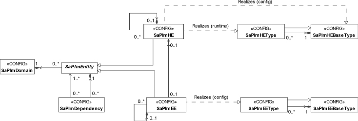
The information model of the PLM shown in Figure 5.3 is part of the system information model [62] maintained by the SA Forum Information Model Management service (IMM) [38] and follows its conventions.
Figure 5.3 The PLM information model [62].
5.3.3.1 PLM Domain
The PLM information model is rooted in the PLM domain object. The PLM domain represents the scope of entities a given PLM implementation manages. The hardware expected to be present in this PLM domain is configured as sub-trees of HEs rooted in this domain object. We discuss HE in details in Section 5.3.3.2.
The system software running on these HEs is represented as EEs. They may compose the last few tiers of the HE sub-trees or may compose separate sub-trees of EEs rooted directly in the PLM domain object. EEs are presented in Section 5.3.3.3.
The tree organization of the represented entities describes their dependency in terms of containment or hosting, for example, a compute blade hosting an OS instance is the parent of the EE representing the OS. Additional dependencies can be defined through the dependency class described in Section 5.3.3.4.
The model also permits that the PLM domain contains only EEs or only HEs.
5.3.3.2 Hardware Elements, Their Types, and Status
The HE represents some hardware within the PLM domain which in turn is mapped into one or a group of HPI entities (Section 5.2.3.2).
The HE is a configuration object describing for PLM the hardware expected to be present in the system. PLM will try to map it into an HPI entity among those discovered through the HPI. The HE is a purely logical entity, which does not manifest in any way in the realms of PLM. The actual manifestation is part of the HPI realm, where the HPI entity maps it into a piece of hardware.
The purpose of this logical HE entity is to provide PLM with enough information to perform the mapping, thus verify the hardware configuration of the system. Once the mapping is established the HE object is used
- to reflect the runtime status of the mapped physical hardware; and
- as a reference to this hardware in the interactions with PLM clients and administrators.
Let's say we have a CPU blade plugged into the fourth slot of our Advanced Telecommunication Computing Architecture (ATCA) chassis; this is the physical hardware. The HPI entity representing it at the HPI level has the entity path {{CPU blade, 0}{slot, 4}{ATCA chassis, 1}{root, 0}}, which is used to identify our blade within the HPI realm. At the PLM level PLM may have mapped it successfully into the CPU3 HE object within the information model and by that PLM verified the correctness of the hardware configuration. As a result PLM sets the entity path attribute of the CPU3 HE object to the entity path {{CPU blade, 0}{slot, 4}{ATCA chassis, 1}{root, 0}}.
From the entity path we can see that at the HPI level there are more HPI entities in the system: at least the slot and the ATCA chassis. The PLM configuration does not necessarily reflect these. The CPU3 HE could be placed in the model directly under the PLM domain object.
The CPU3 HE object may represent the entire blade as a single entity or may have child HE objects representing the different hardware components such as memory, processor, or the firmware on the blade.
The choice is based on whether we would like to expose the states and the control of these HPI entities via PLM.
Each HE has two important attributes: the HE base type and the HE type, which represents a particular version within the HE base type. A HE base type specifies an HPI entity type and it is a collection of different implementation versions of this entity type, each of which is described as a separate HE type. More precisely, each HE type qualifies the HPI entity type of the HE base type with information found in the HPI inventory data record (IDR) management instrument, for example, indicating the vendor, the product line, the model, and so on.
Considering the example CPU3 above it may indicate that it needs to be a CPU blade by referencing a HE base type specifying this feature. PLM will accept and map any CPU blade in slot 4 as long as it matches the IDR characteristics of one of the versions belonging to the ‘CPU blade’ HE base type in the PLM model. Their characteristics may be very specific or just a few depending on the range of implementations that need to satisfy the relation.
Among the attributes of the HE the attribute showing the HE base type is configured, while the attribute holding the HE type of the HE is set by PLM as the result of the mapping. It tells the HE type matching the IDR information of the piece of hardware discovered by HPI at the location that has been mapped to this HE object. For more details on the mapping procedure itself see Section 5.3.5.1.
To reflect the status of the mapped hardware, PLM defines the presence, the operational, and the administrative states as runtime attributes for HEs. The PLM implementation sets the appropriate values for each of these states based on the information it receives from HPI about the mapped HPI entity and also information gathered at the PLM level.
HE Presence State
The presence state of a HE indicates whether the piece of hardware it represents is present in the system and whether it is active. Its values follow the HPI hot-swap state values; however this does not mean that the hardware actually needs to be hot-swappable. In fact it may not even support all the values defined for the state. The PLM implementation maps any information received from HPI to the specific values of the presence state based on their general interpretation. These values and interpretations are the following:
- Not-present: PLM is not aware of any piece of hardware that would match the configuration of the HE entity. For example, there is no blade inserted into the slot where a CPU blade is expected to appear, or the blade inserted is an I/O blade.
- Inactive: PLM has mapped successfully the HE to a piece of hardware in the system, but it provides no functionality. Effectively the hardware is isolated from the rest of the system. For example, HPI detected a CPU blade, which at the PLM level matches the HE configured for the slot; and HPI reports the inactive hot-swap state for the blade.
- Activating: The activation of the piece of hardware represented by the HE has been initiated, but it has not reached its full functionality yet. For example, HPI reports the insertion pending hot-swap state for the CPU blade after the latches have been closed.
- Active: The hardware represented by the HE has reached its full functionality. It can be used for service provisioning as intended. For example, HPI reports the active hot-swap state for the CPU blade.
- Deactivating: The deactivation or removal of the hardware represented by the HE has been initiated. For example, HPI reports the extraction pending hot-swap state for the CPU blade when someone opens its latches.
HE Operational State
The HE operational state reflects whether PLM is aware of any kind of error condition regarding the piece hardware the HE represents. PLM sets the operational state to disabled when it learns about an error condition in the piece of hardware represented by the HE. Otherwise the operational state is enabled.
PLM may find out about error conditions from several sources: From HPI by monitoring the relevant HPI resources and by analyzing the events reported by HPI; from PLM users who may submit error reports on PLM entities; and by implementation specific means.
Whichever way PLM detects an error, it sets the operational state to disabled and, to protect the rest of the system and prevent fault propagation, it isolates the related piece of hardware from the system. HEs are considered intrinsic fault zones.
To isolate, the PLM implementation performs the operations appropriate for the HE to put it to the inactive presence state. How it does so depends on the HPI resources available for the HPI entity representing the hardware at the HPI level. For example, for an FRU with manageable hot-swap states this would mean setting the inactive hot-swap state. For other HPI resource this could be equivalent to a power-off.
Sometimes PLM cannot initiate or verify the isolation as the hardware is inaccessible. PLM indicates this condition by setting the management-lost and the isolation-pending flags.
The HE operational state becomes enabled when the represented hardware is physically removed from the system, or if PLM receives a report that the error condition has been cleared.
HE Administrative State
The administrative state reflects to what extent the HE may offer its functionality within the system. It is controlled solely by administrative operations that PLM receives via the administrative API. Here we only provide the values that the administrative state may take. We will look at its control in Section 5.3.4:
- Unlocked: The HE is not directly blocked from providing services.
- Locked: The HE may be in the active presence state, but is being blocked from providing service. As a result all of its child entities are also blocked. For example, if the HE hosts an EE when the HE is locked PLM makes sure that the EE does not come up or if it is running PLM shuts it down. However if the HE is active one may run diagnostics on it as it is not related to service provisioning.
- Locked-inactive: The administrator forces the isolation of the HE and all its dependants from the system. It is put into the inactive presence state.
- Shutting-down: The HE may continue to serve existing users, but it may not accept new service requests. When the last existing user completes the administrative state of the HE changes to locked.
5.3.3.3 Execution Environments, Their Types, and Status
An EE may represent an instance of an OS, a VM hosting an OS, or a hypervisor hosting, and managing some VMs.
The common theme among these entities is that they are often referred as system software as each of them is a kind of container, which is capable of running some other software entities while managing system resources. They also expose some control interface through which the hosted software entities can be controlled individually or as a collective.
Since within the container itself, the different software shares the different resources fault propagation may occur even between otherwise independent pieces. Consequently the representation of the different containers, the EE is considered as a barrier to fault propagation. It is an inherent fault zone and therefore it is used for fault isolation.
In the PLM information model a HE representing some HPI entity may host at most one EE and vice versa an EE is hosted on exactly one HE.1 This single EE may be an OS instance or a hypervisor—also referred as virtual machine monitor (VMM).
This single EE may host additional VM and OS instances all sharing the computing facilities of the HPI entity and consequently all impacted by a failure of this HPI entity. Obviously any software running in these EEs will also be impacted, therefore for availability management it is essential to be aware of this lower level organization of the system when, for example, one decides about the distribution of redundant entities among EEs.
Being a fault zone and reflecting the organization of fault zones are the features that the EE logical entity introduces to the system information model. It also exposes a simple and uniform management interface for these different software entities that PLM users can rely on without the need to be aware of the specificities of each of these system software entities.
The PLM implementation is responsible for mapping the administrative control operations and the state information between the particular software instance represented by the EE entity and the PLM administrator. Doing so PLM may interact with the software instance using a Portable Operating System Interface for Unix (POSIX) [73] like interface in case of an OS instance, or use some API such as libvirt [74] for managing the virtualization facilities.
In either case, PLM does control the life-cycle of the EE software entities. So we can say that there is an actual entity in the system, which corresponds to the configuration object in the information model and which is managed by PLM. PLM also controls the type of the EE instance starting up, which means that if the booting software does not correspond to the expected EE, PLM is at least able to prevent it from the completion of booting, but typically it is able even to initiate the boot of the correct software.
To determine whether an EE is the correct one, the PLM information model defines EE base types and EE types. The base type specifies at least the vendor of the EE, but it may also indicate the product and the release. The EE type identifies a particular version within a base type. It also provides some instantiation and termination parameters for the type applicable to all EE instances of the type. For example, the EE base type may say that it is a particular vendor's Enterprise Linux line. It may have several EE types depending on the various versions used in the system, and for each it would indicate the appropriate instantiation and termination timers.
Looking at the EE object class used to configure each EE instance in the system; it references the EE type as a configuration attribute based on which PLM can determine if the booting instance is the expected one.
As we have seen in Section 5.3.3.2, this approach differs from the approach used with HEs which only configures the HE base type. This difference reflects the fact that PLM controls the version of the EE booting as opposed to just detecting the version of the HE plugged into the system.
Each EE object also provides the state information for the EE instance it represents. The PLM specification defines the same set of states for the EE as for the HE. That is, it defines the presence, the operational, and the administrative states. The interpretation of these states is slightly different though than it is in the case of HEs, reflecting the EE's software nature.
EE Presence State
The presence state of an EE reflects its life-cycle. The EE presence state may take the following values:
- Uninstantiated: The system software represented by the EE object is not running, PLM has not started or detected its instantiation.
- Instantiating: The instantiation of the system software has started either by PLM initiating it or automatically after the hosting hardware reached the active presence state.
- Instantiated: The system software represented by the EE object has completed its startup procedure and reached the state where it is capable of providing the desired operating environment.
- Instantiation-failed: The system software did not reach the fully operational state within the applicable time limit. It failed to instantiate.
- Terminating: The EE presence state is set to terminating as soon as the procedure to stop an already instantiated EE has been initiated. The termination typically starts first with the graceful termination of the software entities hosted by the EE followed by the termination of the EE itself.
- Termination-failed: PLM sets the presence state of an EE to termination-failed if after the applicable timeout it still could not verify the successful stopping of the EE instance.
As opposed to the HE presence state which follows the HPI hot-swap state definition the EE presence state definition is aligned with the presence state of Availability Management Framework (AMF) [48] entities. The main difference compared to AMF is that there is no restarting state for EEs. In AMF the restarting state reflects that any assigned service function logically remains with the entity during its restart. A lack of this state at the PLM level reflects that there is no such expectation for PLM entities mainly because AMF and the other AIS services manage themselves the life-cycle of their entities and perform service recoveries as appropriate. A PLM level service recovery could contradict to these higher level actions.
EE Operational State
The EE operational state is very similar to the HE operational state. It reflects whether the PLM implementation is aware of any type of error condition of the represented EE instance.
PLM sets the operational state to disabled
- if the EE presence state becomes instantiation-failed or termination-failed;
- if it detects an error condition in the EE in some implementation specific way; or
- if it receives an error report for the EE.
Whenever the EE enters the disabled state, the PLM implementation is responsible of isolating it from the rest of the system to protect the system and prevent any fault propagation. This means the abrupt termination of the EE instance, which PLM carries out via the entity hosting the faulty EE. It depends on the management capabilities of this host entity how PLM achieves this task.
For example, if the EE resides directly on a HE, PLM may power off or reset the hosting HE. If the EE is a VM hosted by a hypervisor, the hypervisor typically offers the control to terminate the particular VM and the PLM implementation would use that.
As in the case of HEs, when PLM cannot initiate or verify the isolation due to the relevant entity being inaccessible it indicates the condition by setting the management-lost and the isolation-pending flags.
PLM re-enables the EE operational state if it receives a report that the EE has been repaired by the administrator or the error condition was cleared.
EE Administrative State
As for HEs, the EE administrative state reflects whether the EE may offer its functionality for its users. The EE administrative state is controlled via administrative operations, which we will discuss later in Section 5.3.5.2.
The EE administrative state has the following values:
- Unlocked: The EE is not prevented from providing service.
- Locked: The EE may be instantiated, but it is prohibited from providing service. For example, for an EE representing an instance of the Linux OS the locked state may mean that it runs at a lower init level.
- Locked-instantiation: The EE must not be instantiated. For example, PLM may use the hypervisor's control capability to block the instantiation of a VM, or for an OS hosted directly on an HE assert the reset state of this hosting HE.
- Shutting-down: The EE may serve existing user, but it may not accept new service requests. Once all existing users have been served the EE enters the locked state.
5.3.3.4 Entity State Interaction
As PLM entities change their states they impact each other, allowing or preventing the other to provide services. Whether an entity can provide any service is reflected in its readiness status. The path along which the entities impact each other is determined by the dependencies among the entities.
In this section we present how this essential for availability management information is defined and maintained by PLM. Subsequently in Section 5.3.4, we present how PLM users can obtain this single most important information.
Readiness Status
The readiness status reflects to what extent an HE or an EE is available for service. It is composed of the readiness state and the readiness flags.
The readiness state summarizes the presence, the operational, and the administrative states of a PLM entity itself and the readiness state of the entities it depends on. It has three values:
- In-service: When the readiness state is in-service it indicates that
- the PLM entity is
- healthy—its operational state is enabled;
- capable—its presence state is active or deactivating in case of an HE, and instantiated or terminating for an EE; and
- permitted of providing services—its administrative state is unlocked. And
- all the entities the PLM entity depends on are also in the in-service readiness state.
- the PLM entity is
- Out-of-service: A PLM entity is out-of-service when it is
- not capable—it is disabled or it is in a presence state other than
- active or deactivating in case of an HE;
- instantiated or terminating in case of EEs; or
- administratively prevented from supporting service provisioning—it is locked, locked-inactive, or locked-instantiation; or
- missing a dependency such as its container entity being out-of-service, for example, due to being locked.
- not capable—it is disabled or it is in a presence state other than
- Stopping: A PLM entity enters the stopping readiness state when the administrator moves it or an entity it depends on to the shutting-down administrative state.
The readiness flags further refine the readiness state. There are six flags qualifying the information provided by the readiness state:
- Management-lost flag: It indicates that the PLM implementation has no management access to the PLM entity; any state information for the entity needs to be taken with a grain of salt as PLM cannot verify the information and the state values which represent the last known values may be old data.
The following two flags can only be used in conjunction with the management-lost flag:
- Admin-operation-pending: The PLM could not perform or verify the execution of an administrative operation due to the loss of management access.
- Isolate-pending: Because of the loss of management access, the PLM could not isolate or verify the isolation of the PLM entity.
- Dependency: By setting this flag PLM indicates that the PLM entity is not in-service due to a state change of an entity that the PLM entity depends on, rather than due to a state change in the PLM entity itself.
- Imminent-failure: PLM uses this flag when it receives or detects some indications that a currently enabled PLM entity may become disabled any moment (e.g., a sensor may have signaled the stepping over of some threshold). However at the moment there is no state change yet. Effectively it is a warning recommending users to abandon the use of the entity for which it is set to prevent sudden service impacts.
- Dependency-imminent-failure: Same as imminent-failure but rather than by its own fault the PLM entity is expected to become unavailable due to a dependency.
PLM Entity Dependencies
PLM entities are organized in sub-trees under the PLM domain object. This tree organization is interpreted as a dependency resulting from containment and it also implies a top-down propagation of the state change implications.
Let us assume a chassis having slots which house blades that are carriers of mezzanine cards, each of which may host an OS instance. If a mezzanine card fails it can no longer run the OS it hosts; if the carrier blade breaks none of the mezzanine cards can run their EEs or provide their other functionalities, and so on. The presence and operational states of these entities interact in this manner according to the specification, which reflects reality.
Depending on the hardware architecture, the representation of hardware dependencies may not be this straightforward. It is also influenced by the choice of which HPI entities one wants to reflect in the PLM model.
For example, the CPU, the memory, the hard drive, the I/O card all may be necessary to run an OS instance, but they may be different pieces of hardware, which means that they show up as different HPI entities and accordingly they may be represented in PLM as different HEs. In the tree representation these HEs could be children of an HE representing the board. The question is where in the tree should be the EE object reflecting the OS requiring all these elements.
To properly reflect this relation besides the tree organization the PLM information model also includes the configuration object class that indicates dependencies among PLM entities. Using objects of this class one could define that although it is the HE mapped to the CPU HPI entity that hosts the OS, this EE also depends on the HEs representing the other devices (i.e., memory, hard drive, and I/O card).
Hardware platforms built for high-availability systems typically encompass some—a lot of—redundancy. Among others, this is the reason why they are often built as a chassis capable of housing many identical blades. These blades then are connected through redundant communication paths including redundant switches and powered through redundant power supplies.
For the correct operation of the system, however, at any moment in time not all of these redundant devices are needed. It is enough that at least one of the duplicated devices is available. The dependency class allows the reflection of this constraint.
The PLM dependency object defines the way a PLM entity (HE or EE) depends on a set of other PLM entities. It is used for each set of redundant entities and it specifies how many entities in the set need to be available for service to satisfy the dependency.
‘Available for service’ here means that the readiness state is not out-of-service. In other words, at least the indicated number of entities of the set needs to be either in the in-service or in the stopping readiness state.
For example, for the chassis with dual power supply we could specify that the chassis has a dependency on two power supplies and at least one of them must not be out-of-service.
The dependency—whether it is implied through containment or defined through dependency objects—impacts the readiness state of the dependent entity.
In case of containment all ancestor entities need to be in the in-service state for the PLM entity to be able to stay in the in-service state. If any of them moves to the stopping or the out-of-service readiness state, the dependent entity moves with them. In other words, if an entity moves to the stopping or out-of-service readiness state, all its in-service descendant entities move with it immediately.
In case of a dependency relation configured using the dependency object class, if an entity requires m out of the set of n entities, then for the entity to be in-service at least m of these n entities need to be in-service. If at least one of these m entities moves to the stopping readiness state the dependent entity also moves to the stopping readiness state.
In conjunction with the readiness state the dependency readiness flag indicates that the entity is stopping or out-of-service due to a dependency (regardless of whether it is specified through the tree hierarchy or the dependency objects) and not as a result of a change of its own state values.
The dependency-imminent-failure flag is used to indicate that an imminent failure may occur due to a dependency; however, this does not change the readiness state of the entity for which it is reported. It is a warning. An HPI sensor stepping over a sensor threshold may set the imminent-failure flag for the related HE. PLM propagates this to all its dependent entities by setting their dependency-imminent-failure flags. For the propagation PLM takes into account both the containment and the dependency objects.
It may be interesting to look at how some virtualization features may be represented using dependencies. As we mentioned earlier, if an EE is hosted on a HE it can be configured as the child of this HE. If it is a hypervisor it could be the parent of a set of dependent child-EEs. We can represent each VM and its OS as such a child-EE of the hypervisor EE. These will be the leaf objects in the PLM information model.
Such a representation, however, fixes the relationship of these child-EEs with the HEs and the hosting hypervisor due to the naming convention used in the information model discussed in Section 4.3.1.3. This conflicts with one of the desirable feature of virtualized environments, namely that VMs may migrate.
Instead, one may configure such migrating VMs using dependencies. In this case the migration enabled VMs would be configured as direct descendants of the PLM domain, each of which depends on a set of hypervisors which are configured as leaves of the HE sub-trees. As long as at least one of the hypervisors is in-service and ready to host the VM, the VM can be migrated to it and can be in-service as well. Note however that at the moment PLM is not required by the specification to manage this migration nor it is specified how the dependency object reflects which hypervisor hosts the VM at any given instance of time.
Dependencies just like the PLM domain are not typed objects in the PLM information model.
5.3.4 Tracking of PLM Entities
For PLM users the most important aspect of platform management is that through its track interface it can provide them with up-to-date information about the readiness status of the different PLM entities within the system. This includes readiness state changes, readiness flag changes, but also allows the users to
- verify planned administrative operations to ensure that they do not cause service interruption;
- gracefully execute administrative operations; and
- detect domain reconfigurations, such as adding or removing PLM entities.
The PLM track API supports single time inquiries as well as continuous monitoring.
To receive such indications first of all a PLM users needs to identify the set of PLM entities that it would like to track. The PLM does not specify any default set of entities like we have seen in HPI, that is, all entities visible in a domain.
The PLM user may create this entity group by either listing the distinguished names of all included PLM entities explicitly, or naming the root entities for the sub-trees within which optionally all, only HEs, or only EEs entities are tracked.
Tracking a sub-tree allows the detection of PLM entities added to the sub-tree, while tracking of status changes and removals is possible regardless of whether the entities are listed explicitly or implied by a sub-tree.
A PLM user may choose to receive the readiness status information for the entire entity group in each callback or only for those entities that have a change in their status.
The tracking may involve three steps: the validation, the start, and the completed.
They enable the validation and graceful execution of different controlled operations as well as the tracking of spontaneous changes as they occur in the system. A PLM user may subscribe to track all three steps, the last two or only the completion step.
The user requests the different options and the entity group to be tracked when it initiates the tracking.
As changes occur or being proposed in the system, a PLM implementation continuously evaluates their impact on the PLM entities and sets their different states and status flags as appropriate. Whenever there is a potential impact on the readiness status of some entities being tracked, PLM informs those subscribers that have registered their interest for the impacted entity.
If the change is a proposal—such as a try-lock discussed in details in section ‘PLM Lock and Unlock’—PLM considers the validate step first.
If the change is a request to carry out a controlled operation gracefully—such as a shutdown—then PLM moves directly to the start step.
If the change is abrupt such as a failure, PLM can only inform the interested parties for which it uses the completed step.
In any case first, PLM calculates the list of PLM entities that have changed or would change their readiness status. This is the set of impacted entities.
5.3.4.1 Validate Step
The goal of the validate step is to negotiate whether the proposed change is acceptable for all the parties that registered their interest for such negotiation. The PLM specification defines the acceptability criterion as whether the proposed change would cause any service outage.
The validate step implies the following actions:
- PLM evaluates if there is any PLM user process tracking any of the entities the readiness status of which is impacted by the proposed change. If there is a PLM user that requested a callback in the validate step for any of the entities, PLM shall inform this user about the proposed change.
- PLM calls back each user who tracks an entity group that contains at least one impacted entity. For each of the entities, PLM indicates its current readiness status and the status it will have after the change is accepted.
- The tracking user has the choice either to accept the proposed change or to reject it depending on whether it expects any service outage as a consequence. In either case it needs to respond to PLM indicating its choice. Accepting the operation also means that the user has made all the necessary preparations to avoid service outage if the change is carried out. For example, the user may make some resource reservations.
Note that these preparations cannot still guarantee that there will be no outage during or after the change as failures may happen in the system any time. However it should ensure that if a second operation is validated before this change takes place; the validation will take into account the combined effect of the two operations.
- When all users that received a callback from PLM for the validate step have accepted the proposed change, PLM proceeds with the start step to deploy it. If any user rejects the proposed change, the operation is aborted:
- PLM calls back the same set of users as for the validate step to inform them that the proposed change has been cancelled and they may release any resource that they reserved in response to the validation request.
PLM also communicates the rejection to the initiator of the change (e.g., HPI, the administrator).
Once the proposed change has been validated successfully the change cannot be canceled any more and PLM proceeds with its deployment through the start step.
5.3.4.2 Start Step
The start step guarantees the graceful deployment of the changes by executing it in a top-down manner. This is achieved by first initiating the change toward PLM users, that is, toward the upper layers, and then waiting until these users indicate that they have completed all the necessary actions. Only after this confirmation the operation is deployed at the PLM level.
The start step involves the following actions:
- PLM evaluates the set of PLM user processes tracking the impacted entities for the start step. That is, those users that requested callback for the validate step or for the start step.
- PLM calls back the identified set of users to requests them to carry out any action required to avoid service impact from the initiated change. To be able to evaluate the impact at their level, PLM provides them with the current and the new readiness status (i.e., when the operation is completed) of the impacted entities.
For the PLM (or higher level) users (e.g., AMF) this means that they may need to re-arrange the provisioning of their service so that they avoid using the PLM entities going out-of-service. Any reservation made in the validate step would be used at this time.
- Once the evacuation is completed, users respond to PLM indicating that they are prepared for the change and PLM can apply it. That is, PLM can perform all the necessary actions related to the initiated readiness status change without service impact.
- When all users have responded toward whom the change was initiated, PLM deploys the changes at the PLM level and sets the different states and flags as appropriate for the change.
The operation is complete and PLM reports this fact to the initiator.
With this, however, the tracking process is not over yet as there might be users who requested track callbacks only for completed operations.
5.3.4.3 Completed Step
The completed step is the bottom-up signaling mechanism of PLM to inform its users about readiness status changes in the system.
PLM notifies its users only in the completed step whenever
- entities become available for service;
- they fail unexpectedly;
- the administrator forces an operation (see Section 5.3.5.2 for more details); and also when
- a user tracks only completed changes.
With the completed step PLM also confirms the committed changes toward those users who track the validation or start steps.
The completed step involves only a single action: PLM calls back all its users that track any of the impacted entities regardless the tracking step option. With this callback PLM informs them that some entities they are tracking have changed their readiness status and it provides these changes in the callback.
PLM does not expect any answer to the completed step.
5.3.4.4 Tracking Side Notes
The most important thing to understand about the tracking API is that the tracking processes are not necessarily the same as the entities impacted by the readiness status changes at the PLM level. In fact in the AIS architecture, the tracking entity is the CLM and not the ‘cluster node’ itself, which is CLM entity impacted by the readiness state change at the PLM level.
This shows that the tracking API is geared toward management entities in the system and it provides means for these entities to obtain the information necessary to avoid service impact in a timely manner.
It is the responsibility of these management entities to find out the correct list of entities they need to track in order to be able to maintain SA and to start the tracking process with PLM.
To track the correct PLM entities these management entities need to understand the relation between the entities they are in change of and the PLM entities. The PLM has no idea about this relation or any other upward relation. It only handles relations between PLM entities and toward HPI entities. Doing so, however, PLM releases the higher level management entities from processing this low level information in all its details.
It is also the PLM users' responsibility to interpret the changes, that is, their consequences. For example, considering the locked administrative state, which is defined as the entity out-of-service but instantiated or active, it is implementation dependent how or whether PLM can achieve it at all that such an OS instance is not used by any nonsystem process to fulfill the ‘out-of-service’ status.
Similarly for a locked HE not hosting an EE what it means that it is not allowed to provide services while being fully functional otherwise is not defined.
This means that while PLM changes and signals the readiness status of the impacted PLM entity, PLM may not guarantee that all the dependent entities indeed will experience the change immediately. It is a management entity tracking to the readiness status that can enforce the proper reaction of higher level entities.
Finally, it is also interesting to note that neither the validation nor the start steps are time limited. The PLM specification does not define timers for them, so they may potentially take a very long time.
The reasoning behind this is that these steps are used in cases when there is a way to escalate the operation. As we will see in the following sections, if the try-lock takes too much time, the administrator may escalate it to a normal or a forced lock; or if after opening the latches the signal indicating the completion of the evacuation does not come in time, the board can be taken out unexpectedly for the system, which will perceive this as a failure.
5.3.5 Administrative and Management Aspects
There are two aspects of the administrative control of the PLM that require discussion:
- Configuration: As mentioned earlier, the expected configuration is described in terms of HEs and EEs and their types. PLM uses this information to match the HPI entities detected in the system with the HEs and to control the EEs booting on them.
- Administrative operations: The administrator may issue different administrative commands on PLM entities or manipulate the platform physically. These actions control the administrative and other states of the targeted entities. The key feature of the PLM administrative API is that it offers the try option which succeeds only if the operation causes no service outage.
In this section we look at each of these aspects.
5.3.5.1 Mapping HPI Entities to PLM Entities
In the course of our discussion of the HPI we have seen that it detects the hardware composing the system and presents this information to each of the domains defined in the system as a DET and a RPT (see Section 5.2.4). The first lists all the HPI entities visible in the domain, while the second lists the management resources available on these entities including the IDRs. In addition the DRT lists additional domains in the system.
Conversely, the PLM information model includes three relevant sets of management objects: (i) the objects representing the expected in the configuration HEs; (ii) these reference the objects representing HE base types that indicate the expected HPI entity types; and (iii) for each HE base type there is a set of HE type objects, each of which refines further characteristics of the different implementations of this HPI entity type.
These management objects of the PLM information model describe the expected configuration of the hardware.
The task of a PLM implementation is to match up the expected configuration with the actual one, that is, the HEs of the information model with the discovered HPI entities.
The PLM specification outlines the matching procedure only at a high level. It implies approximately the following procedure:
PLM opens a session on the default HPI domain to gain access to the DET, RPT, and IDRs. It also reads the PLM information model:
For the matched HEs PLM sets the state information based on the readings of the RPT for the matching HPI entity. In particular PLM changes the HE presence state from ‘not-present’ to the one matching the detected status.
If after investigating all HPI entities in DET there are still unmatched HEs and there are also other nonpeer HPI domains present in the DRT, the PLM implementation moves on to investigate those domains if there are more entities visible from them that could match the still unmatched HEs.
It is possible that PLM cannot match all the configured HEs. They will remain in the PLM information model with missing runtime entity path attribute until HPI detects a new entity that would satisfy their matching criteria. PLM subscribes to the HPI domain events to get informed about such events.
It is also possible that PLM discovers that the HPI entity at a particular location is different from the expected one. PLM will generate an alarm for such a case.
As we noted, the matching procedure described in the first release of the PLM specification only at a high level and therefore it can be implemented in different ways. This may result in a situation in which taking the same HPI information and the same PLM configuration, two PLM implementations will match up the entities differently and may find different sets of unmapped HEs and/or unmapped HPI entities.
Once the HPI entities are mapped to the HEs the PLM implementation figures out from the RPT of the entities domain what management capabilities these entities have and how these relate to the control operations PLM needs to perform.
We have already mentioned that the most important operation is to be able to isolate the HPI entity from the rest of the system whenever PLM or anyone else in the system detects an error on it. This of course also requires that PLM identifies how to detect errors on the different HPI entities.
At the moment of writing the PLM specification does not describe how this functional mapping is performed.
5.3.5.2 PLM Administrative Operations
Due to their different nature, the PLM defines slightly different sets of administrative operations for HEs and EEs. Table 5.1 gives a summary of the PLM administrative operations.
Table 5.1 PLM administrative operations
| Hardware element | Execution environment | Effect |
| Physical removal of hardware | n/a | Change the HE presence state to not-present and uninstantiated for its EEs |
| Physical insertion of hardware | n/a | Attempt to match the HPI entity and change the states of the mapped HE as appropriate |
| Unlock | Change the administrative state to unlocked | |
| Lock | Change the administrative state to locked | |
| Shutdown | Change the administrative state to shutting-down | |
| Deactivate | Lock-instantiation | Change the administrative state to locked-inactive/locked-instantiation |
| Activate | Unlock-instantiation | Change the administrative state to locked |
| Reset | Restart | Cycle the presence state |
| Repaired | Change the operational state to enabled | |
| Removed | Unbind the management object from the entity | |
Except for the operations marked as physical, an administrator issues these administrative operations through the IMM object management (OM) interface [38] on the objects representing in the PLM information model the targeted PLM entities.
Physical Insertion or Removal of Hardware
In Table 5.1 we have taken into account as PLM administrative operations the physical insertion and removal of hardware entities. The world of hardware and software meets at the PLM level also in the sense that we can talk about ‘hard’ and ‘soft’ administrative operations.
When carrying out a ‘soft’ operation, the administrator interacts with the PLM implementation via the administrative API. This gives PLM the possibility of either accepting or refusing the operation and also of enforcing a particular way of its execution.
On the other hand, when someone decides to physically manipulate the hardware, that is, to perform a ‘hard’ operation, the PLM and HPI implementations have little chance to control the actions. They may need to resort to detecting the physical manipulations. These may or may not follow the intended execution order. If they do not, then the ‘offending’ action is mapped into a failure condition and handled accordingly as we already noted at the discussion of HPI in Section 5.2.5.
In any case, the PLM implementation finds out about any physical manipulation of the hardware from HPI, which detects and reports them to its subscribers as events.
When a new hardware is added to the HPI domain HPI generates an event and the detected HPI entity with its management capabilities is added to the DET and its resources to the RPT. In the subscriber PLM implementation, this event triggers the HPI entity matching procedure as described in Section 5.3.5.1.
The mapping can only be successful if the PLM configuration contains a HE matching the properties of the inserted HPI entity. The mapping may fail for different reasons, such as the entity is not represented in the PLM model or the previous mapping was not deterministic and now it conflicts with the hardware configuration. The key point is that PLM is not required to remap HEs. In fact to avoid any service impact, it must not remap them while they may be providing service. Remapping is only allowed for entities in the out-of-service readiness state.
When PLM cannot map an HPI entity it may generate an alarm. In the alarm PLM is not required to indicate the reason for the mapping failure or whether remapping may clear the alarm. Moreover, the first version of the specification also does not specify any administrative operation to initiate a remapping.
In case of successful mapping, PLM sets the different states and flags for the mapped PLM entities based on the reads it collects from resources managing the HPI entity. PLM calls back any of its users tracking any of the PLM entities that change readiness state as a result of the insertion. The callback is issued in the completed step only (see Section 5.3.4.3).
When a piece of hardware is being removed from an HPI domain, depending on the type of the HPI entity, HPI may generate one or several events. As we have noted in Section 5.2.5, if the entity is not a hot-swappable FRU, an HPI implementation may interpret the removal as a failure of the HPI entity and signal it accordingly.
If the HPI entity is hot-swappable, HPI signals a series of hot-swap state changes. These changes may or may not be manageable and in addition the person performing the operation may or may not take into consideration the signals reflecting the state control.
PLM processes the signaled HPI events and if the entity being removed maps to a HE or impacts PLM entities it changes their state information according to the signaled event and generates the appropriate track callbacks.
In particular when HPI signals an extraction pending event for a hot-swappable entity (e.g., as a result of opening the latches of a board), which is mapped into a HE currently available for service, PLM attempts to cancel any HPI deactivation policy to gain control of the extraction process and if successful PLM tries to drive the extraction through the three-step tracking procedure as described in Section 5.3.4:
It initiates the validate and starts steps toward its users to evacuate all the services from the impacted HE. When this is completed, PLM also terminates any EE requiring the HE. At completion finally PLM sets the HPI resource hot-swap state to inactive thus allowing HPI to complete the operation at its level.
However, any time during this process the person performing the extraction may ignore PLM's attempt to control the process and may proceed with the extraction. This takes the HPI resource representing the HPI entity's hot-swap state to not-present which is reflected at the PLM level by setting the same value for the presence state of the mapped PLM HE and with that the readiness state goes out-of-service for all impacted entities. This results immediately in a track callback in the completed step notifying about the change, which cancels out any previously initiated validate and start steps for the entities.
If the HPI entity does not have the hot-swap capability or it is unmanaged, PLM only signals the completed step to its users.
Note that if the PLM entity is out-of-service at the insertion or removal of the mapped HPI entities then no readiness status change occurs and therefore no track callback is needed.
HE Deactivate and Activate
The ‘soft’ version of the insertion and removal of HEs are the HE activate and deactivate commands respectively, which control the administrative and if applicable the presence state of the HEs.
The biggest difference however is that while physical manipulation bypasses the administrative state of the PLM entities, the HE deactivate and activate commands do not. As a result these operations can be issued even on HEs whose presence state is not-present, in which case only their administrative state is changed. In addition PLM may set the management-lost and the admin-operation-pending flags for the HE indicating that it could not execute some part of the operation as in reality PLM may not always be able to tell apart if the entity is not there or it is inaccessible.
When the entity is inserted to the system, its state is controlled by the setting of the administrative state of the HE it is mapped to. That is, if it is locked-inactive the presence state can only change from not-present to inactive and PLM will maintain it there as long as the administrative state remains so. The presence state may change to activating only after the administrative state has been changed.
The activate command changes the administrative state of the HE from locked-inactive to locked. The operation is invalid for HEs in any other administrative state.
Moving to the locked administrative state allows the mapped HPI entity to start activating and eventually become active. However, it still may not offer any services, so its readiness state remains out-of-service, which means, for example, that no EE is allowed to boot. It also means that no change is signaled on the tracking API.
The counterpart of the activate command is the deactivate, which is only valid on a HE, which is in the locked administrative state and therefore it should not provide any type of service. Accordingly, the operation has no service impact. The deactivate command changes the HE's administrative state to locked-inactive and its presence state to deactivating followed by inactive.
Due to the required for the operation locked state, the entity is already out-of-service and its deactivation does not cause any change in the readiness status that would initiate any track callback.
PLM Lock-Instantiation and Unlock-Instantiation
The deactivate and activate commands apply exclusively to HEs. Their equivalents for EEs are the lock-instantiation and unlock-instantiation commands.
The same way as for the HE deactivate and HE activate, the EE lock-instantiation operation is only valid for EEs in the locked administrative state, and the unlock-instantiation only for EEs in the locked-instantiation state. As a consequence the state changes caused by these operations do not cause readiness status change and do not need to be signaled via the track API. Only the presence state may be impacted.
When the administrator initiates the lock-instantiation of an instantiated EE PLM terminates the EE and its presence state transitions to the uninstantiated state in addition to the administrative state changing to locked-instantiation.
When the administrator issues the unlock-instantiation command, PLM allows the instantiation of the EE in question; however, since it still remains in the locked administrative state it is still not allowed to provide services. For example, if this is a hypervisor, its child EEs remain uninstantiated.
The same way as the HE deactivate and activate commands do not require the actual presence of the mapped entity, the lock-instantiation, and unlock-instantiation also can be issued regardless of the EE presence state. In these cases PLM will set the management-lost and the admin-operation-pending flags for the EEs as well.
PLM Lock and Unlock
The lock and unlock operations apply to both HEs and EEs. They control whether a PLM entity may offer its services or not, which is reflected by the administrative state of the entity. Due to this state change the readiness state may also change which is most important for SA. That is, the administrator needs to be aware of its action, whether the entity goes out-of-service and potentially impacts others too.
From the perspective of the SA Forum services of the system that need to be available are managed by the AMF [48] as described in Chapter 6. AMF reflects in its information model the distribution of assignments among the AMF provider entities as a dynamically changing mapping, which follows the changes that occur in the system.
The relations between the AMF service provider entities and the PLM entities are also not obvious even though they are not changing dynamically. The reason is that they are represented in separate sub-trees of the system information model and they are mapped through the CLM entities composing a third sub-tree as shown in Figure 5.1 and described in Section 5.4.3. As a result figuring out the impact of a PLM entity on the services managed by AMF is not straightforward.
In addition, the service outage we are interested in is not in the current state of the system, but the way it changes due to a lock operation, that is, once the target entity and entities requiring it become locked and stop servicing. All of this depends on the actions AMF and the other services will make as a result of the lock.
This makes it hard if not impossible for the administrator to foresee if there is a service impact.
As a solution PLM offers different flavors of the lock operation:
- Try lock, which evaluates whether the operation causes service outage and if it does, then the operation is aborted.
- (Normal) lock, which gracefully carries out the operation to its end. That is, PLM informs its clients about the operations and waits until the services are evacuated from the impacted entities at higher levels and completes the lock only after it receives a confirmation from its clients.
- Forced lock, which carries out the lock without informing anyone in advance. PLM provides only postmortem notification.
PLM uses the appropriate options of the three-step track to communicate to the interested processes the changes occurred or about to happen.
For the try-lock operation PLM uses the track callback starting with the validate step as describe in Section 5.3.4.1.
If any user rejects the lock operation, it is aborted by PLM also using a track callback. PLM also informs the administrator about the rejection of the try lock. Once the validate step has been accepted for a try-lock, PLM carries out the operation continuing with the start step as if it was a normal lock operation.
For the normal lock PLM invokes the track callback in the start step requesting its users to carry out at their level any preparation necessary to prevent service impact caused by the targeted PLM entity going out of service. It is up to each PLM user to interpret what this means. We will see that, for example, the CLM simply passes on this information to its users, such as the AMF, which needs to move the service assignments away from the AMF entities going out-of-service as a result of the PLM entities going out of service. Ideally if this step has followed the validation step, AMF is able to evacuate all the services.
Once the evacuation is completed, the PLM users are expected to confirm that PLM can proceed with the lock of the PLM entities. Thus, PLM completes the administrative operation at its level and locks the target entity's by setting its administrative state to locked. With this, the entity's readiness state and the readiness state of all entities requiring it go out-of service. As a finishing touch PLM informs all its users tracking any of the impacted entities about the change by a final callback in the completed step.
As a result of a force administrative lock, PLM immediately executes all the actions required at its level to lock the target entity and by that PLM takes it out of service together with all impacted entities. Only after this, PLM informs its users tracking any of the impacted entities in the completed step that the target entity has been locked. Obviously in this case no service impact is taken into consideration at the execution of the operation.
Even in the earlier cases the service impact can only be considered to the extent that the PLM track API is used by the availability management.
The lock operation may be issued on PLM entities which are in the unlocked or the shutting down administrative state. It may also be repeated on the same entity as an escalation of the operation to a stronger option. That is, a try lock may be escalated to a normal or forced lock, and a normal lock to a forced. One may consider this escalation if the completion of the weaker option takes too much time since these operations are not time limited within the PLM.
If the entity is already out-of-service at the time of the lock operation—this may happen if it is disabled or missing a dependency—then none of the track steps is needed at all. The operation completes right away with PLM setting the locked administrative state for the entity.
The unlock operation moves the administrative state of a PLM entity to the unlocked state. This may or may not change the readiness state of the entity depending on its dependencies and operational state. If there is a missing dependency still or the entity itself is disabled the readiness state remains out-of-service.
Otherwise it becomes in-service, which results in a callback to all users tracking the target entity and any other PLM entity which becomes in-service together with it.
As a result of becoming in-service dependent entities may also change their states, for example, a HE hosting an EE now can start up this EE provided the EE itself is not locked for instantiation. If the unlocked entity is a hypervisor, it is also allowed to start up its child EEs that are allowed to instantiate.
PLM Shutdown
The interpretation of the administrative shutdown operation is that the target entity may continue to provide its services to existing users, but it has to reject new user requests. This is reflected with the shutting down administrative state.
When the service is completed for the existing users the shutdown operation is completed and the entity moves to the locked administrative state. The operation is valid only for entities in the unlocked administrative state.
As we have seen already the notion of the ‘service’ is rather vague for PLM entities, so distinguishing their existing and new users becomes virtually impossible—at least for the PLM itself. For example, for an OS the shutdown state could mean that no new processes can be started, which may be hard for PLM to enforce as the underlying OS does not typically support such a notion.
As a result the PLM shutdown operation is seemingly identical to the ‘normal lock’ operation except for the administrative state value.
If the entity was in-service at the moment the shutdown is issued, its readiness state changes to stopping, which means that PLM needs to inform users tracking the entity about the state change. As for the ‘normal lock’ operation PLM indicates to its users in the start step that a shutdown has been initiated. It proceeds with locking the PLM entities only when all called back users confirmed that they have completed the shutting down operation.
The key difference is not in what PLM does, but what it requests from its users. In the case of the lock operation the users are expected to evacuate the services from the impacted entities right away, while in the case of the shutdown they are expected to perform a shutdown operation by rejecting new users at their level. This does not require evacuation. They continue to serve existing service users. Thus, the time to perform a shutdown operation may be significantly longer than that of the lock operation.
As mentioned earlier, the PLM specification does not have a time limit for the start step, neither the lock nor the shutdown are restricted. The specification also does not mandate any particular behavior for the case when a PLM user cannot evacuate all the services due to lack of resources. It is left up to the user what strategy it defines for such a case. It may respond to PLM as soon as it evacuated all the services that were possible to evacuate potentially resulting in a service outage due to the completion of the operation at the PLM level. Or it may wait, and wait, and wait if the evacuation eventually becomes possible delaying by that the completion of the PLM lock.
The same applies to the shutdown, except that in this case no evacuation is attempted at all and the PLM user is expected to respond only when all the services ‘die off naturally’ on the impacted entities.
In either case as we have indicated, the administrator may need to deal with the situation that the operation takes too much time. The shutdown operation can be escalated to any option of the lock, which itself may be escalated to a forced lock that applies the operation right away.
On an entity in the shutting down administrative state the administrator may issue the unlock operation to cancel the effect of the shutdown. This returns the entity to the unlocked administrative and in-service readiness state. As always the readiness state change is signaled by PLM via the tracking API. In this case again only the completed step is used.
PLM Restart and Reset
The reset and restart administrative commands cycle the presence state of the targeted entity. Reset is applicable only to HEs and restart is applicable only to EEs. The goal of these operations is typically a repair of some kind.
PLM maps the reset operation to the HPI function setting the reset state of the resource controlling the reset of the HPI entity to which the HE was mapped. The specification does not mandate and the administrator has no control over the type of the reset (e.g., warm, cold, etc.) PLM performs. The mapping depends on the PLM implementation.
The HE reset brings the HPI entity to a known state and therefore it may be used to repair the entity. The reset may however be performed to repair entities hosted on the HE.
An administrator has the choice to restart an EE in a normal fashion or abruptly.
The normal restart means the termination and re-instantiation of the EE itself through its own means. That is, the normal restart is mapped to the appropriate operation of the target EE (e.g., to the ‘reboot’ command in the case of Linux). Note that this typically means an abrupt termination for the entities hosted by this target entity; hence the restart operation isolates them from the rest of the system and may even repair them. However, the EE itself is still trusted to be able to execute the restart correctly.
The abrupt restart, on the other hand, is mapped by PLM to the appropriate operation of the entity hosting the target entity. If the EE resides on an HE directly then the abrupt restart is mapped to the mentioned above HPI reset. If the EE is a child of another EE such as a hypervisor, then the abrupt restart is mapped to this hypervisor's appropriate operation to restart only this given child EE.
As a result the abrupt restart isolates and it may also repair the target entity itself. This operation handles the case when the target EE is assumed to be faulty and cannot be trusted any more.
Whether it is an HE reset or an EE restart, the operation impacts the dependent entities. All child entities may go through their own presence state cycle and the same may happen to entities defining a dependency on the target entity or its children.
The most important impact of the operation is that after successful completion the operational state of disabled entities becomes enabled again.
As a result of the presence state cycle, the readiness state of the target and all dependent entities may also go through a cycle: It changes to out-of-service first and then to in-service if the operation is successful. This means that PLM calls back all the processes that track any of the impacted entities, but all readiness state changes are made only in the completed step regardless of whether the operation is normal or abrupt.
PLM Repaired and Removed
The common feature of the repaired and removed operations is that they inform PLM about some change about which PLM would have no information otherwise.
The repaired operation is applicable only to PLM entities that have their operational state disabled. By applying the operation to such an entity the administrator informs PLM that the entity has been repaired and PLM should try to take it back into service. To ensure correct initialization the entity should be handed over in the inactive/uninstantiated presence state.
If PLM does not detect the error condition any more and it can activate or instantiate the entity then PLM clears all of the readiness flags and sets the operational state to enabled.
If the circumstances evaluate so it also sets the readiness state to in-service. In turn, entities dependent on the repaired entity may also become in-service.
For all the entities changing their readiness status PLM calls back the users tracking them in the completed step.
With the removed operation the administrator indicates that while PLM had no management access to some entity it has been physically removed from the system, while the management object representing it remains in the system. Accordingly, it only applies to entities for which the ‘management-lost’ readiness flag is set. As discussed in section ‘Readiness Status’ when PLM loses management of an entity it only sets the management-lost flag for it and leaves all the states including the readiness state with their last known value. So for a board that was unreachable before its removal the system may still report that it might be still in-service, as are its dependent entities. The ‘might’ is implied by the setting of the management-lost flag.
Thus, this action corrects the state information in the PLM information model that PLM cannot detect by itself since it has no access to the entity. (Recall that normally PLM detects the removal of HPI entities via HPI and of EEs by implementation specific ways.)
As a result of the operation PLM sets the presence state of the impacted HEs to not-present and for EEs to uninstantiated. It also corrects the states of the dependent entities. For entities that change their readiness state as a result of these actions, PLM also informs about the change the users tracking them through a callback in the completed step.
5.3.6 Service Interaction
5.3.6.1 PLM Notifications
The PLM generates a set of alarms and notifications for its entities using the SA Forum Notification service (NTF) [39].
Optionally, PLM may also convert HPI events into a format appropriate for NTF, so they are delivered by the same channel as the notifications of all of the AIS services. This is done in addition to the applicable PLM notifications. That is, an HPI event which triggers some changes at the PLM level is reported by PLM on behalf of HPI as well as on its own, reporting the PLM level change.
As opposed to the HPI event subscription, which delivers all events of the domain, the HPI events converted by PLM into NTF notifications can be filtered based on the event type and some other attributes because these attributes of the HPI event are converted into NTF fields. The rest of the content is provided as raw data in one of the three standard formats or in implementation-specific way. The standard formats are:
- as binary with the most significant bit first;
- as binary with the least significant bit first; or
- in the external representation format defined in [75].
For its own entities the PLM generates the following alarms:
- HE Alarm;
- EE Alarm;
- HE Security Alarm;
- EE Security Alarm;
- Unmapped Hardware Entity Alarm.
Except for the unmapped hardware entity alarm, the PLM specification leaves it implementation specific the exact conditions that trigger the alarms. An alarm is cleared by PLM when it cannot detect the alarm condition any more, for example, because a repair cleared it or the entity was removed from the system.
PLM generates the unmapped hardware entity alarm when it detects an HPI entity, which it cannot map to any HE when applying the matching procedure described in Section 5.3.5.1. There we mentioned the case that the alarm is generated when the HPI entity at a location does not match the HE expected at that location.
PLM also generates this alarm when it discovers HPI entities that cannot be mapped to any HE. The exact criteria of how a PLM implementation determines this fact is not straightforward since the relation of HPI entities and PLM HEs is not 1 : 1, but n : 1. That is, several HPI entities may be mapped to a single HE. For example, the PLM model may only represent the carrier blade, but not the individual mezzanine cards it carries. While HPI has an entity path identifying each of the later ones, they are not considered unmapped by PLM. Instead, all of them are mapped to the carrier blade.
5.3.6.2 Monitoring and Controlling HPI Entities
With respect to the platform hardware, the PLM specification was written with HPI in mind. Nevertheless PLM does not mandate the use of HPI. Any other solution may provide PLM with similar information. In this section we look at the case when PLM uses HPI.
As described in Section 5.3.5.1 when PLM uses HPI, it finds out about the different HPI entities composing the hardware platform using the HPI discovery procedure and maps them to the HEs in its own information model. Since the PLM specification does not describe exactly how PLM implementations should use HPI to accomplish their task, different PLM implementations may have different strategies for the discovery. It is important, however, that a PLM implementation detects all the HPI entities represented as HEs in the PLM configuration and also all the management features offered by this underlying hardware.
An HPI implementation may expose the resources for the same HPI entity in several domains and not necessarily the same way. As mentioned in Section 5.2.3.3, for example, the hot-swap capability of an entity is typically indicated in only one of the domains through which it should be controlled. Other resources in other domains related to the same HPI entity will not indicate it as hot-swappable.
This means that a PLM implementation needs to discover all these domains to become aware of all the available resources for each HPI entity, that is, not just to map them properly to the HEs to the HPI entities, but also to discover correctly their states and the available operations.
To remain up to date with the status of the HEs, a PLM implementation also needs to subscribe to the HPI events of these different domains. Through these subscriptions PLM can learn in a timely manner about the changes occurred in the different domains. These may be state changes of the resources, but also addition or removal of entities.
While the addition and removal events are relatively straightforward to map to PLM, the mapping of other HPI events is not necessarily so.
For example, an HPI resource may report that the temperature measured by a sensor exceeded some threshold, but whether this means a failure and the entity needs to be isolated or it is a warning that indicates an imminent failure, neither of the specifications (i.e., PLM or HPI) defines.
Moreover, since each entity may be exposed through several resources of several domains, it is also possible that the same event needs to be interpreted differently depending on the context of other events reported by other resources in those other domains.
Since no standard guidelines exist, each PLM implementation may have its own slightly (or not so slightly) different mapping of HPI events to the status of PLM entities. They may also react differently to some of these events.
Even for PLM operations (such as the administrative operations) the specification does not elaborate in detail how they map to HPI control operations. It only describes the intended result and the PLM implementation is responsible for the ‘correct’ mapping to the HPI entity to the target HE and its detected management capabilities.
In any case, the complexity of mapping of entities, events, and operations between PLM and HPI is one of the main reasons the PLM was defined and became part of the AIS. It guarantees that at least within a single PLM domain these aspects are handled uniformly and it also frees higher level entities from this burden.
5.3.6.3 PLM Interaction with IMM
As we mentioned already in Section 5.3.3, the PLM obtains the PLM information model from the IMM [38]. IMM also provides the administrative interface for all AIS services including PLM.
All the ‘soft’ administrative operations discussed in Section 5.3.5.2 are issued using the OM interface of IMM (IMM OM-API) and target a particular object representing a PLM entity. In turn IMM invokes the PLM implementation to pass on the request of the administrator. When the operation completes PLM returns the result to IMM, which forwards it to the administrator.
The challenging part in this interaction is PLM acquiring its information model as according to the specification, the IMM provides its services only within the cluster, but the PLM is below the CLM in the architecture; thus, it does not require the presence of the cluster at all.
Therefore we need to make the assumption that there will be a cluster forming on top of the PLM domain. However for the bootstrapping of this cluster the PLM specification does not make any suggestions. We will look at the issue in a bit more details in Section 5.4.3. Here we will assume that the PLM is able to obtain its information model in some implementation specific way at the system startup.
Once the cluster is up and the IMM is available, the PLM implementation registers with it as the implementer of the PLM information model objects and uses this configuration information to bring the platform to the state best matching it. The result is reflected in the runtime attributes of the objects that represent an entity in the system so their status can be monitored by administrators.
Whenever an administrator manipulates the PLM configuration objects, the PLM implementation receives callbacks from IMM to deploy these changes in the system.
5.3.7 Open Issues and Conclusions
At the time of writing only the first, the A.01 version of the PLM has been published yet. This release could not and did not address many of the issues that are in the intended scope of the service. In the course of our presentation of the service we have already pointed out a number of the areas where the current specification is sketchy or incomplete.
One such area of incompleteness is the PLM information model, and in particular the object class describing the EE and its types. They provide currently the basic administrative operations and some state information, but very little configuration information that one may associate with OSs or VMs.
In the future the concept of EE may be refined to potentially address the following:
- Virtualization: It might be advantageous to distinguish the hypervisor, the VM, and the OS instance. For example, one could then associate migration only with the VMs and not necessarily with all three. At the same time, however, there are OSs that encompass the functionality of one or the other, or both.
- Alternative EEs: In real systems particularly for diagnostic purposes, one would like to be able to perform diagnostics without changing the configuration, to have an alternative configuration readily available for this task. The current model provides no solution for this.
- Boot image:Currently the EE class has no information that PLM can use to figure out where to find the boot image for a particular EE instance yet it is expected to control its life-cycle and potentially even switch to the correct EE if the one booting is not correct. There is no information about whether there is only one image or if there are alternatives. For example, if PLM fails to boot the OS from one location whether there is another source to boot it from. Whether the types of these boots are the same or different, for example, network boot versus boot from local disk. All this is left up to the implementation.
- File system, backup, and restore: With respect to the file system available in the SA Forum cluster there is no standard solution. It is not even clear whether this should be part of PLM or a separate service. Its close relation to the boot image and the need of high-availability systems to be able to fall back to a working image after system failures suggest that PLM could be the right places to address these issues too.
With respect to the HEs it is also not clear whether the current model contains enough information for PLM and for system management with respect to the hardware.
The primary goal of the PLM information model is to allow the availability management to evaluate the distribution of logical entities on the physical hardware to minimize the impact of hardware failures. The model also provides a more homogeneous AIS view. It brings the hardware entities into the picture which had to be handled differently before. This means that some functionality defined for PLM seemingly overlaps with the functionality provided by HPI. Yet, PLM provides a higher level of abstraction. It generalizes the many functions that HPI provides into a few essential ones. The level of this abstraction may require refinement in the future.
For example, in HPI there is the FUMI which reflects and controls the firmware version loaded in the hardware. It is a question to what extent this needs to be exposed through PLM in addition to HPI, and whether the firmware needs to be visible at all through PLM when it comes to the management of its upgrades, for example, by the Software Management Framework [49].
There are a lot of open issues, but at this point of time the Technical Workgroup of the SA Forum has decided to take a step back from the specification work and see what requirements will emerge in real implementations of PLM, in their real life deployment. The first release of the specification has set the direction and it is satisfactory to start the implementation work. A PLM implementation will face many of these and even other issues; it needs to provide some solution to them. Armed with the practical experience the SA Forum intends to revisit the specification and refine it to address the issues that indeed require standard resolutions. After all it is a question of why or to what extent would one want to make the platform management service itself platform independent?
As we mentioned at the beginning of the discussion of PLM there was some debates whether the functionality intended justified the creation of a new service or it should have become part of the CLM. The definition of the first release showed that indeed the separate service is justified and we believe that these sections showed the correctness of this choice to the reader as well.
This hesitation, however, somewhat determined the status of the PLM specification within the SA Forum architecture:
The SA Forum architecture does not define the PLM as mandatory. It may or may not be part of a middleware implementation. Moreover the PLM information model is defined so that the hardware and software parts can be used by themselves. They do not require their counterpart.
Also while the specification of the HE is based on the concept and functionality of the HPI, its use is also optional and a PLM implementation may collaborate with any other hardware management interface.
Regarding the EEs there is hardly any reference to any standard interface, although the OS is generally considered to be POSIX [73] compliant.
With respect to the virtualization facilities there were no standard interfaces to rely on. At the time of writing there is already work going on in the Distributed Management Task Force to define some standard virtualization management interfaces [76]. Future releases of the PLM specification may take advantage of their results.
5.4 Cluster Membership Service
5.4.1 Background
The information about the platform that applications and middleware services really would like to know is the set of ‘nodes’ they can use reliably in the provisioning of their services. They need to know the EEs that are healthy, well connected, and provide the computing resources they need; the ones that compose a set presentable to the users as a single logical entity—a cluster.
Most AIS services including the AMF need this information; and applications using AIS services may also require it. Relying directly on the PLM, all of them would need to implement a similar logic that generates this information. At least now that PLM has actually become part of the SA Forum architecture. In reality the CLM [37] was defined first. It was one of the first services defined indicating its essential role and the importance of the information it provides.
The problem of cluster or more generally group membership has been around ever since distributed systems have been used for distributing the tasks they performed. It gained even more significance with the use of such systems to provide fault tolerance.
Chandra et al. [77] provided the following definition: ‘A group membership protocol manages the formation and maintenance of a set of processes called a group. A process group is a collection of programs that adapt transparently to failures and recoveries by communicating amongst themselves and exchanging information.’
Fischer et al. [78] however showed by 1985 that such a consensus could not and cannot be achieved in asynchronous systems containing at least one faulty process.
Luckily the problem of membership is not the same as consensus since to make a decision we do not need to obtain the agreement of the faulty process. That is, the faulty process can be expelled from the group. Nevertheless in [77] it is proven that even with this relaxed model, the problem remains unsolvable for asynchronous primary-partition systems—those that try to maintain a single agreed view of the current membership—as it is impossible to decide whether a process is infinitely slow compared to others or faulty.
The authors of [77] came to the conclusion, however, that any technique that proved to make the consensus problem solvable was applicable also to the membership problem with the same result. These techniques weaken enough the problem specification to make it solvable. They are: randomization, well-defined probability assumption on the behavior of the environment, and use of failure detectors with well-defined properties.
In the context of the SA Forum architecture one may look at the PLM—or any other even proprietary technique—as such a failure detector and therefore making the problem solvable. This still means that CLM is left with the task of the formation and maintenance of the membership in this case from a set of EEs—or in CLM terms nodes; and the group in CLM term is called the cluster.
CLM also needs to provide a distribution mechanism to update with this information all the interested parties—the AIS services and the potential user applications – in such a way that they can synchronize on the content.
5.4.2 Overview of the Cluster Membership Service
The SA Forum Application Service Interface identifies the CLM as the authority on the cluster membership and all services and applications requiring this information should depend on the CLM. It is in charge of forming the membership from the nodes configured for the cluster and of providing its users with up-to-date information about the membership.
From CLM perspective a node is a logical entity that represents all the software executing on an instance of an OS that what in PLM terms is an EE.
The group of nodes intended to collaborate in a location transparent manner is called the cluster. Nodes are configured for cluster membership, but at any given moment it is possible that not all configured nodes are part of the membership. A node which is part of the membership is referred to as a member node.
To become a member node, a node needs to satisfy a number of criteria. Namely,
On practice this means that in addition to the OS some daemons of the middleware need to be up and running. It is implementation and configuration dependent exactly what daemons need to be available to make, for example, the AIS services available for user applications.
The reachability needs to be such that it allows for the location transparent collaboration of middleware services and applications. This means that the users of these applications and services should not be aware from where and from which node they are being served within the cluster; they should obtain the same service with the same result.
Among the AIS services at least the CLM needs to be available for application software executing on a node. As mentioned earlier, other services also might need to be provided depending on the middleware implementation and the system configuration.
The CLM node itself and all PLM entities it relies on need to have the permission of the administrator to provide services. In sections ‘HE Administrative State’ and ‘EE Administrative State’ we have discussed the administrative state of the PLM entities. In Section 5.4.5 we will take a look at the administrative control of the CLM.
If any of these criteria is not satisfied the CLM does not allow the node to join the membership, or if the node is already a member, CLM expels the node from the membership.
The CLM specification does not describe how a CLM implementation verifies for each node that it meets the above list of criteria. However requirements #1 and #4 imply that the readiness state of the PLM EE the node resides on is in-service or stopping and CLM can obtain this using the PLM track API as described in Section 5.3.4. The method used to verify the rest of the criteria is left to each of the implementations.
It is also left to the CLM implementation how it forms the membership, that is, what protocol it uses to establish a single view of the membership.
A view is the list of nodes that are part of the membership and an associated view number, which is an integer. Any time a node joins or leaves—by whatever reason—the cluster CLM transitions the membership to a new view. Most importantly this new view is associated with a number greater then any previous view. This increment ensures that any receiver can easily identify the latest view among a series it has received. The view numbers of subsequent views, however, may or may not be consecutive numbers.
In the membership nodes are identified by their name and their node id. The two have different life spans.
The node gets a unique node id when it joins the membership and keeps this id for the time it is part of the membership. When the node leaves the membership its id may be recycled by CLM.
The node name, on the other hand, is independent of membership; it is unique in the cluster and remains constant even after a particular node has left the membership and then rejoined it again.
The CLM exposes the different views to its users through a tracking API similar to that discussed at the PLM in Section 5.3.4.
The main simplification, however, is that either a single predefined ‘entity group’ or a single entity are traceable via the CLM API. This single entity group is the cluster. Alternatively, users may also track the node on which they reside as an individual entity.
This means that the users do not need to be aware of the cluster configuration. Beyond these two options they do not need to define which entities they want to track. They can learn about nodes as they become part of the cluster from the views they receive from the service. That is, no prior knowledge of configured nodes is required at all.
As one can see from Section 5.4.1 it is a challenging task to establish a single view of the cluster membership. The challenge lies not only in timing issues, but in the fact that in distributed systems it is always difficult to distinguish whether the remote entity itself is down or it is actually up, but it is unreachable due to some communication failure or just very slow.
In high-availability circles the dreaded condition is when two disjoint subsets of cluster nodes are up, but cannot communicate with each other and therefore form independent memberships; this is called the ‘split-brain’ scenario. It may not be obvious, but it goes against SA.
The problem is that in this case we have two subclusters visible from the outside world each as the whole. For the users they are indistinguishable as both have the same identity. Unwittingly they present themselves as ‘the cluster,’ but obviously users access one or the other part, also knowing nothing about the existence of the second part. Since the two parts are unaware of each other changes made in one part are unknown to the other and over time they may show up for a user as discontinuity.
Imagine that the cluster is used to maintain your bank account and you deposit $1000 accessing let's say part A while the cluster happens to be split into parts A and B. Next moment when you want to transfer some of this amount to somewhere else you happen to access the other part B, which then informs you that your money has gone and that you have overdrawn your account. You freak out and with good reason.
Consolidating after such a scenario is rather difficult and may turn out to be impossible without any loss of information.
In the CLM specification there is one requirement related to the issue. It says that when a node leaves the cluster CLM needs to reboot the node to guarantee that no services are left running on the leaving node.2 However, it does not specify how to determine which one is the leaving node and which one is remaining in a—let's say—two-node cluster; or under what circumstances one node is a cluster.
A CLM implementation needs to resolve these issues so it protects against all such scenarios and guarantees that at most one cluster entity is exposed to the external world at any given moment.
The CLM specification also does not address timing issues. For example, the time frame within which CLM users can or need to learn about new views is neither specified with respect to the actual membership transition, nor with respect to different CLM users between each other. The only requirement is that if two users receive two views from the CLM referring to the same view number then the list of member nodes must also be the same. The view numbers provide the synchronization point when parties compare their views of the membership.
Obviously a membership view is useful if the users receive this information in a timely manner. There is little use in knowing the list of member nodes once the actual membership has changed. In certain circumstances this timing issue may become critical.
Most of the AIS services should only be provided on nodes that are members and, as we indicated at the beginning of this section, CLM is the authority on determining the current membership.
Hence the AIS services are required to use the CLM to obtain the current membership information and provide or withdraw their services accordingly. These changes in the membership also trigger recovery actions such as service fail-over at the level of the AMF. The faster AMF learns that a node left the cluster the earlier it can react and recover the services provided by that node. So the timely signaling of membership transitions is a determining factor in failure recovery.
It is again left to the CLM implementation to make sure that it comes up with the new view in a short enough time that does not hamper SA and that the information is provided across the membership within a short time.
We have to clarify that as dire as it might sound we do not criticize the Cluster Membership specification itself. It is an API specification and users do not need to be aware of any of these issues; hence they do not need to be part of the specification.
It is the CLM implementation that needs to deal with these issues and provide an appropriate solution. As a result, however, depending on how successful different implementations are, for example, in the convergence of the membership view, they may provide quite different user experience and characteristics of SA.
5.4.3 CLM Configuration: The Bootstrap Trap
The information model of the CLM describes the configuration of the cluster. Accordingly it has only two configuration object classes: one to represent the cluster and another to represent the configured cluster nodes.
At the root of the system information model a single cluster object represents the CLM cluster and its child objects represent the CLM nodes configured in this cluster.
The cluster object is very simple. It has a single configuration attribute: the cluster name.
The CLM uses the information of the objects representing the configured nodes to identify which nodes of the system can participate in the membership. If applicable, two essential pieces of information are provided here: The PLM EE on which the node should reside and the address to access the node.
As in other services the CLM node configuration objects also provide the attributes that indicate the status of each node: First of all, whether it is in the membership or not.
If the node is a member then it has a node id and a current address through which it is accessible and which may be different than the configured address.
Additional attributes indicate the view number at which the node has joined the cluster and when it has booted. These pieces of information become decisive whenever a node wants to rejoin the cluster to determine whether it can do so or it should be rebooted first.
Even though the information model defines these different runtime attributes all as mandatory they need to be handled differently. Some of them have a meaning only when the node is a member. For example, the node id has such a life-cycle. Others, like the boot time, contain information significant after the node left the cluster. By keeping the boot time in the model, a CLM implementation can easily decide whether to admit the node to rejoin the cluster based on how its current boot time compares to the one kept in the model.
Note the chicken-and-egg issue regarding the CLM information model. It is about this requirement that AIS services should provide their service only on nodes that are members of the cluster. This requirement is applicable to the IMM as well, which appropriately holds the configuration information necessary to form the cluster. Obviously, the same applies to PLM, which also needs to learn its configuration from IMM before it can map the HPI entities to HEs that in turn host EEs hosting CLM nodes required to form the cluster before IMM can provide the service to obtain the necessary configuration information.
There are several generations of poultry involved here!
Again, the solution to this bootstrap is left to the Cluster Membership implementation and it will be different from one environment to the other, from one implementation solution to another.
Because of this variability the consensus within the SA Forum Technical Workgroup was not to put any requirements on the bootstrap process. In fact there is a consensus that the requirement on AIS services that they should provide their services on member nodes only is applicable only after cluster formation, but not during the cluster bootstrap.
5.4.4 Are You a Member?
Among the AIS services providing cluster-wide service, the CLM is an exception as it provides some of its services on configured nodes that are not members of the cluster yet. This allows CLM users to find out when the node becomes a member. This is useful as up to this moment they cannot initialize any of the services that should be provided only on member nodes. They are unavailable. To receive this information a user needs to start tracking the cluster membership.
CLM provides the following information on nodes: node name and id, network address, the hosting EE and its boot time, the membership status, and the view number when the node joined the cluster.
As mentioned earlier there are two options of tracking with respect to the scope of entities. A user may choose to track the local node, that is, the one it resides on or the entire cluster. In neither case it needs to know the actual name or identifier of these entities to start the tracking. The choice is controlled by the track local flag. If it is set only the local node is tracked; if it is not set, the entire cluster is tracked.
The other tracking options are similar to those available in the PLM track API discussed in Section 5.3.4. That is, one may receive information about the changes only or on each change the complete information for the selected scope.
As in case of the PLM track API, CLM also provides the three-step tracking option primarily to be able to pass on these steps to its users when they are initiated at the PLM level. We will not go through the details here again as they are essentially the same as discussed in Section 5.3.4.
The main difference is that CLM maps the PLM entities and the reported impact to CLM level cluster nodes and effects on them. In its callbacks CLM reports the affected nodes with the anticipated (for validate, start, and abort callbacks) or actual (for the completed step) CLM level impact.
In addition to passing on PLM reported events, CLM uses the track API to report also cluster membership changes independent of PLM. As we have seen, the CLM has its own responsibilities in evaluating and maintaining the membership. Whenever it detects or initiates a change, for example, by expelling a node that does not satisfy the membership conditions any more, CLM reports these changes to its users through the track API; typically in the completed step.
However, although the CLM administrative operation expels the node from membership, CLM uses the start step similar to the PLM normal lock option; therefore it is strongly recommended for applications and services responsible for SA to use the CLM track API at least with the start option. For more on the administrative operations please see Section 5.4.5.2.
In the same way as for PLM, CLM expects an answer from its users after callbacks in the validate and starts steps. In the validate step the response indicates whether the proposed change has service impact and therefore it is rejected by the user, or no service impact is expected and the user accepts the change. Again users accepting the change should be prepared for it when it is carried out subsequently in the start step. If the change is rejected by at least one user CLM aborts the proposal.
The response to the start step indicates whether the users completed the evacuation from the impacted nodes. If the entire membership is tracked, the user receiving the callback needs to evaluate itself whether the evacuation applies to it, while tracking the local node implies this, as the callback always contains the information with respect to the node where the user receiving the callback resides.
As opposed to PLM, the CLM uses some time supervision for its callbacks, and in the callback it indicates the time within which it expects the response. When this attribute is set to zero, it means that no response is required such as for the completed step. When the attribute is set to ‘unknown time,’ CLM will wait indefinitely for the answer the same way PLM does.
An important nuance is that within a single initialization of the CLM a user can have only a single tracking session through which it may either track the entire membership or the local node. Subsequent invocations to the track API only modify the options of this already initiated tracking by logical ORing (i.e., applying the logical OR operator to the current and the new flags). Subsequent invocations do not result in additional tracking sessions.
However, there is no limit to how many times a user initializes the CLM service. Through multiple initializations of the service the same user can start multiple tracking sessions each with different options, for example. Doing so however requires the correlation of callbacks as the same change may be reported by CLM in multiple callbacks. This should be possible as each callback includes the root cause entity.
In addition to the track API, which ‘pushes’ the information to the users at the time of the changes, the CLM provides an API by which users can pull the status of individual member nodes. This API is only offered on nodes that are members and applicable only to member nodes since the inquiry is based on the node id, which is valid only during membership.
5.4.5 Administrative and Management Aspects
The CLM defines three administrative operations; all three are applicable to cluster nodes only and manipulate its administrative state. These operations are the unlock, the lock, and the shutdown. We start our discussion with the review of the administrative state, which is the only state defined by CLM.
5.4.5.1 CLM Node Administrative State
In the CLM only cluster nodes have an administrative state, which indicates whether the node is eligible for membership. An administrator manipulates the administrative state through the administrative operations. The current value of the administrative state of each node is presented in the CLM information model as a runtime attribute.
The cluster node administrative state has three values:
- Locked: The cluster node is ineligible for cluster membership.
- Unlocked: The cluster node has not been administratively prohibited from joining the cluster. Whether the node will join the membership depends on whether it satisfies the membership criteria presented in Section 5.4.2.
- Shutting-down: The administrator requested that the cluster node gracefully transitions to the locked state. If the node is not a member node, it makes the transition immediately. If it is a member node, CLM user processes residing on the node are expected to follow ITU X.731 [72] shutting down semantics: ‘Use of the resource is administratively permitted to existing instances of use only. While the system remains in the shutting down state the manager may at any time cause the managed object to revert to the unlocked state.’
To better understand the mechanism enforcing these states let's see the administrative operations.
5.4.5.2 CLM Node Lock and Shutdown
The lock and shutdown operations are very close relatives as the goal of both is to put the CLM node into the locked administrative state. Now let's see how this is achieved because this gives an interesting insight to the operations.
In both cases CLM uses the track API to inform its users about the issued operation. CLM invokes the callback in the start step to request its users to perform the actions necessary for the execution of the initiated administrative operation, which is indicated as the cluster change for the target node.
Then CLM waits for the responses from the users in case of the shutdown operation indefinitely, in case of the lock operation at most for a configurable time period. Whenever CLM receives all the responses or if the timer expires, CLM proceeds with the administrative operation: That is, it locks the node and reboots it to guarantee that no process using AIS services remains on the node. CLM informs in the completed step its remaining users tracking the membership that the node has left the cluster.
In case of the administrative operations, the reboot on exit is applicable regardless of the configuration attribute disabling node reboot.3 The rational of this is that the intention behind the option of disabling reboot is not to hamper applications that have a long startup up procedure when the node ‘accidentally’ drops out of membership, for example, due to intermittent connection. Since in case of the administrative operation the dropping out is not accidental, all the rules of leaving cluster membership should apply.
There are a number of differences between the lock and shutdown operations. We summarized them in Table 5.2.
Table 5.2 Comparison of the lock and shutdown administrative operations
| Lock | Shutdown |
| Applicable to administrative state | |
| The lock operation is valid on nodes in the unlocked and in the shutting down state. Hence it may be used as an escalation of the shutdown operation. | The shutdown operation is only valid on nodes in the unlocked administrative state |
| Administrative state | |
| For the lock operation the administrative state remains unlocked until all responses are received or the timer expires, at which point it is changed to locked. | For the shutdown operation the administrative state is changed right away to shutting down and it remains so until CLM receives all the responses when it changes to locked; or a new administrative operation overrides the shutdown operation. |
| Time supervision | |
| The lock operation is time limited. CLM waits at most a configured period of time to receive all responses. At the expiration of this period CLM proceeds with the operation regardless. | The shutdown operation is unlimited in time and CLM will wait as long as it takes to receive all the responses before it proceeds with locking the node. |
The consequence of using the track API to perform these administrative operations is that the presence of tracking users determines whether the operation is applied right away or it goes through the start step of the tracking. On a member node if there is no user to call back, for both operations CLM expels the node from the membership immediately at the initiation of the operation. This means that services and application responsible for SA can avoid service impact by becoming CLM users and using the track API.
When there are tracking users, it is left up to the user how they react to each of the operations. The fact that the lock operation is time limited suggests that users should evacuate their services from the node as soon as possible. In case of the shutdown operation there is no such urgency at least from the perspective of the CLM. The reason for not having time limit for the operation is that the same way as for PLM, the administrator can always escalate the shutdown operation to a lock, which then guarantees that the operation will succeed within a time limit.
5.4.5.3 CLM Node Unlock
The node unlock administrative operation reverses both the lock and the shutdown operations in terms of the administrative state. It moves the node to the unlocked administrative state.
In case the node is still in the shutting down administrative state, it has not left the cluster yet and therefore the only action CLM needs to take is to inform tracking users about the state change. It does so in the completed step.
An already locked node has already left the membership. Once the node is unlocked the CLM evaluates whether it satisfies the membership criteria as described in Section 5.4.2. If it does, the node may rejoin the cluster and when it succeeds CLM announces it to its tracking users in the completed step.
5.4.6 Service Interaction
All AIS services providing cluster-wide service are required to use the CLM to determine whether a node is a member or not and adjust their services accordingly. This means that from the perspective of CLM all these services are user processed. CLM is not aware of their identity. It is the responsibility of the AIS service implementation to use the CLM therefore we do not discuss this interaction any further.
The CLM is a user to three AIS services: The NTF, the IMM, and the PLM. Here we take a look at these. In addition to these services a CLM implementation may also use the Log service (LOG) and other AIS services, however the specification requires only the mentioned three.
5.4.6.1 CLM Interaction with NTF
The CLM does not generate any alarms, but it generates notifications on nodes entering or exiting the membership, on node reconfiguration and on administrative state changes.
All these notifications follow the generic structure of the state change notifications defined in the NTF specification. They allow one to follow the membership changes without the use of the track API. The main difference is of course that there is no possibility to influence these changes and that notifications may be delayed or suppressed compared to the track callbacks.
Since the NTF is also a cluster-wide service the bootstrapping issue discussed in Section 5.4.3 is very much applicable. It also means that the monitoring of cluster membership via notifications is available only on the member nodes as opposed to the track API.
5.4.6.2 CLM Interaction with IMM
We have already pointed out in Section 5.4.3 the bootstrap trap with respect to the CLM configuration. The CLM is also expected to obtain its configuration from the IMM, which offers its services only on member nodes—it is a Catch-22 [79].
Assuming that a CLM implementation resolves this catch in some implementation specific way and completes the bootstrap it registers with IMM as the implementer for the CLM node and the CLM cluster configuration objects which represent respectively the cluster node entities and their collection, the cluster. The CLM implementation maintains these logical entities according to the configuration requirements of the representing objects. It also updates the configuration objects' runtime attributes as necessary, so administrators (and management applications) can monitor the cluster status via IMM.
The IMM also mediates any administrative operation and configuration change between an administrator and the CLM implementation. Whenever the administrator initiates an action IMM calls back the CLM implementation to deploy the action in the system. CLM reports back the changes to IMM, which then delivers the results to the administrator.
5.4.6.3 CLM Interaction with PLM
The trickiest of all is the CLM interactions with the PLM. Obviously CLM needs to be a user of the PLM track API. The question is what entity group it needs to track. The specification does not specify this and lets implementations choose their own solution.
To see the nuances that an implementation needs to consider let us assume a configuration of four cluster nodes residing on four PLM EEs. Each of these EEs are an OS instance running in a VM EE that are hosted by two hypervisors residing on two physical nodes represented as HEs. This means that if any of the HEs are turned off, two of the CLM nodes leave the membership. For a CLM user (such as AMF), providing highly available services, it is essential to know this consequence.
PLM reports the track callback based on the entity groups. This means that if the two nodes residing on the same HE form different entity groups, PLM will provide two callbacks one for each entity group, and CLM may map them into two independent membership changes, so in turn the CLM user may start to evacuate its services from one leaving node to the other.
Although with all the parameters provided in the track callbacks it is possible to correlate subsequent callbacks with each other and identify the scope of impact, this can only occur at the moment when all callbacks triggered by a single event have been received. Unfortunately a receiver cannot know if there is a subsequent related callback still to be received. As a result it should react at the first callback, which means that it may initiate the wrong reaction.
If CLM creates and tracks an entity group containing all the EEs hosting cluster nodes, it receives in each callback the complete picture for the cluster, that is, all the EEs impacted by the event being reported.
It is also essential that CLM itself does not split up the information received in a single callback into multiple callbacks to the same user, that is, it should report all leaving nodes in a single callback and not generate a callback for each node.
The reason the CLM tracks PLM entities obviously is that the Platform Membership service provides essential information about the health of these entities, which is a key factor in the evaluation of the eligibility of each node for membership. However, the specification does not mandate that this is the only determining factor. As we have seen, PLM may report that it lost management access to an entity, which does not necessarily mean that entity is faulty and cannot be used for service provisioning. This means that CLM may need to resort to its own resources to figure out whether the node using the entity remains eligible for membership.
PLM may also represent in its model entities that do not map into cluster nodes, but which represent resources enabling the cluster formation. For example, the switch or the network interface cards may be reflected in the PLM model and a CLM implementation may track these PLM entities in addition to those hosting CLM nodes to evaluate the health of member nodes and the cluster as a whole and to use this information for the cluster formation and maintenance.
5.4.7 Open Issues
The CLM is among the services defined first within the AIS. In addition as Section 5.4.1 pointed out, the problem has been studied for decades. As a result the CLM specification can be considered mature at this time.
There are only a few open issue not addressed in the specification available at the time of writing. The first one is the dynamic configuration of the cluster and cluster nodes. Considering the relatively few configuration attributes this is quite straightforward and the next release should remedy it.
The case is similar for the next issue: There is a need to have more than one address represented in the information model for each cluster node.
A more complicated issue is the relation of the PLM domain and the CLM cluster. The current AIS specifications limit this to 1 : 1. However one can easily imagine cases when a single cluster is spread over multiple physical locations that are managed at the PLM level as different domains; or the opposite, when a single PLM domain hosts multiple CLM clusters; and any configuration in between.
These configurations are increasingly interesting for real deployments. They do not necessarily contradict to anything defined by today's CLM. The reason they are not covered by the specification is merely that these cases were not investigated thoroughly as one would like to do when it comes to guarantees about SA.
5.4.8 Recommendation
Since the CLM is the authority on the cluster membership, all applications and services that need this information (because e.g., they provide cluster-wide services) should use the CLM.
In addition applications and services requiring any piece of information returned by CLM such as a node's network address or hosting EE may prefer to use the CLM API instead of finding out the information via the IMM OM-API.
5.5 Conclusion
This chapter presented the services providing information about the platform at different levels and granularities. We presented the way this information is collected and presented to the users. We started out with the details on the discovery of the hardware platform through the HPI, the information it presents to its users, among them to the PLM.
PLM uses the received information to match it with the expected hardware configuration and complements it with the information available on the EEs providing the runtime platform for software entities. PLM exposes the results in the information model available as part of the system information model and also through the PLM track API.
The CLM forms the cluster among the configured nodes residing on EEs reported by PLM as healthy and ready for service provisioning. CLM checks and monitors additional conditions to continuously verify each nodes eligibility for the cluster membership. It provides the membership information to its users who should rely on this information in all decisions related to membership, such as whether they can use any given node to host their own entities or provide their services to users residing on a particular node.
As the information percolates up through these layers it becomes more and more abstract focusing on the key objective: To provide the platform users with reliable information on the nodes available for service provisioning at any moment in time. This is the single most important piece of information most applications and services need to achieve SA and it is provided by CLM.
Users requiring more details and tighter control over particular platform entities can obtain this in the appropriate details yet in a standard platform independent way using any of the lower level platform services, that is, PLM or HPI. Hence this layered platform solution provided by the SA Forum specification can satisfy the needs of a wide variety of applications whether they are geared toward SA or not.
1 In reality it may be the case that more then one hardware element is required for the execution environment. The PLM specification calls for selecting the most important HE as the hosting entity. See also discussion on dependencies in section ‘PLM Entity Dependencies.’.
2 Note that this behavior can be overridden by the configuration as for some software the startup time may be unforgivingly long and therefore the reboot needs to be avoided. However in such cases the particular solution has to provide the equivalent guarantees.
3 Disabling node reboot may prevent a CLM implementation from protecting against the split-brain and other scenarios, which need to be considered before setting this option for any CLM node.