CHAPTER 4
Storage Hardware
In this chapter, you will learn how to
• Classify storage networking devices
• Differentiate between the types of cables used for storage
• Select removable storage options that best fit a business scenario
The previous chapters covered disks and their operation as well as the function of RAID groups. This was followed by technologies that utilize the capacity and speed of many disks together to provide storage to direct attached or networked hosts over a storage area network (SAN). Next, the methods for communicating over storage networks, called protocols, were discussed. This chapter builds on the previous chapters by introducing the hardware that storage networks are built upon.
Cables
Cables of all shapes, lengths, and compositions make up the networks that connect our offices, homes, schools, and the world. Cables are a medium through which data, represented as light or electromagnetic waves, travels from source to destination. Most high-performance networks are composed of physical cables that connect devices together. Cables provide faster speeds and greater security than wireless networks, and they have a long history of use. The two main types of cables used in storage networking are optical and copper cables.
Analog vs. Digital
The cables and media types discussed in this chapter will be either analog or digital, so it is important to understand the difference between these transmission and storage methods. Analog data is transmitted as a signal that varies in power level, which is called amplitude, and number of waves in a time period, which is called frequency.
Figure 4-1 shows an analog signal. Each wave in an analog signal can represent a discrete value, of which there are many (in fact, infinite) possibilities. For example, when a person sings a note, the note is an analog sound wave that hits our ear at a certain frequency, and the loudness of the voice is determined by the amplitude. When sending data, the amplitude is used to specify the piece of data such as an A from a B. The downside to analog is that it is easily susceptible to noise and interference, which makes determining the amplitude of the wave more difficult and results in data errors and retransmission. Figure 4-2 shows a noisy analog signal. For this reason, analog communications have error detection and retransmission safeguards built in, but the addition of these safeguards results in more information that must be transmitted that consumes a portion of the available bandwidth, known as overhead.
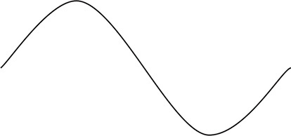
Figure 4-1 Analog signal

Figure 4-2 Noisy analog signal
Digital signals differ from analog signals in that one of only two values is specified: 1 or 0, on or off. Figure 4-3 shows a digital signal.

Figure 4-3 Digital signal
Nominal amplitude is interpreted as a voltage close to 0, usually 0.00 to 0.8 volts; higher amplitude, such as 2.5 to 5.0 volts, is a 1. The great difference between nominal and higher amplitude makes it easier to differentiate between a 1 and 0, so digital communications are more resistant to noise. Figure 4-4 shows a noisy digital signal. The downside to digital transmissions is that they can represent only one of two values at a time, so while a single analog waveform could represent an A, digital communications would need a series of eight waveforms to represent the letter A in ASCII as 01000001.

Figure 4-4 Noisy digital signal
Analog storage, similar to analog transmissions, can store one of many possible values in a discrete location, while digital storage represents only a 0 or a 1 in each discrete location on the media.
Optical Cables
Optical cables transmit data via light impulses. They are made of thin transparent glass or plastic core inside a protective cladding. Light travels very fast and over long distances, but the speed of light is not constant. Rather, it depends upon the medium it travels through. Light travels at 186,000 miles per second in a vacuum such as space and approximately 100,000 miles per second in fiber-optic cables. The high speed at which light travels makes optical cables a low-latency form of communication. This means that little time passes between when data is sent and when it is received.
Optical cables have several advantages over copper cables. They are not affected by interference such as electromagnetic interference (EMI) or radio frequency interference (RFI), and they are relatively small compared to copper cables, so more optical cables can be placed in the same location. Optical cables also offer the highest transmission rates and can transmit much farther than copper cables. Finally, fiber cables protect sensitive electronic equipment from damage from power spikes because they do not conduct electricity. However, optical cables are more expensive than their copper counterparts.
Optical cables can transmit multiple pieces of data at the same time by using different light wavelengths, what we might interpret with our eyes as colors, for each segment; this method is called wavelength division multiplexing (WDM). WDM uses a multiplexer to combine the signals and a demultiplexer at the receiving end to split them into their individual signals again.
It is much more difficult to splice optical cables than copper cables. Optical cables must be combined mechanically or fused in a process similar to soldering except at a much more delicate scale. Fiber-optic cores are about the size of a human hair, and the fusing must ensure that the light signal is not attenuated when passing through the fused portion. Once the cores of both cables are aligned, an electrical pulse is used to burn off residue, and then a larger electrical pulse fuses the two components together. On the positive side, the difficulty of splicing optical cable makes them more resistant to unauthorized access through tapping.
There are two main types of optical cables: single-mode fiber (SMF) and multimode fiber (MMF). SMF can transmit at longer distances, but it is more expensive and transmits at lower data rates. MMF works at higher data rates but shorter distances at lower cost.
Single-Mode Fiber
Single-mode fiber uses a single beam of light generated by a high-precision laser to transmit data over a fiber-optic cable. The beam travels down the center of the core without reflecting off the edges. This allows for the signal to be sent great distances without suffering from much attenuation because the shortest distance between two points is always a straight line. SMF is more expensive than MMF, and it is harder to work with. SMF splicing has to be much more precise because of its small size and the need for precise alignment. Fiber cables are often referenced by their core and cladding sizes, such as 9/125, which has a 9-micron core and a 125-micron cladding. SMF cables will have core sizes less than 10 microns in many cases.
Multimode Fiber
Multimode fiber, as the name implies, uses multiple light beams generated by a light-emitting diode (LED) at the same time to achieve greater speeds than SMF. Each beam is emitted at a slightly different angle. The beams reflect off the inner wall of the core many times before reaching the destination, and MMF is designed with a grade index on the inside part of the cladding to bring the beams to the destination at the same time; however, there is some variation, and this does not always happen. MMF signals can arrive at different times since some will reflect off the inside edges of the cable more often than others. This is called modal dispersion, and higher data rates result in more pronounced modal dispersion, which reduces the maximum data rates or lengths for MMF. The core of MMF is larger in diameter than SMF. MMF’s larger size allows for the use of less expensive LEDs instead of lasers. MMF cables will have a core size between 50 and 62.5 microns. Some older cables had a core of 100 microns, but they are now obsolete. An example of an MMF cable would be 50/125, which has a 50-micron core and a 125-micron cladding. The process for transmitting multiple light impulses at different wavelengths is known as multiplexing.
Multiplexing in Optical Cable
Multiplexing, or WDM, is the process for transmitting multiple light impulses at different wavelengths. There are two types of WDM, known as coarse wavelength division multiplexing (CWDM) and dense wavelength division multiplexing (DWDM). CWDM is used for multiplexing anywhere from two to eight wavelengths over a single optical cable, whereas DWDM is used for multiplexing more than eight wavelengths, typically 32, 64, or 128 wavelengths, but at a higher cost than CWDM. CWDM is used for short-range communications, whereas DWDM is used for long-range communications. CWDM wavelengths use wide-range frequencies that spread wavelengths far apart from one another so that they do not drift into one another and overlap, causing a loss of data.
Limitations
The maximum length of optical fiber depends on the data rate, with higher data rates reducing the maximum transmission length since higher data rates suffer greater from attenuation. Attenuation is primarily caused by scattering when light collides with atoms in the glass. SMF can transmit at 10 Gbps at a distance of several thousand kilometers and 40 Gbps at several hundred kilometers, while MMF can support speeds up to 100 Gbps but for only 150 meters. MMF’s range extends to 550 meters when transmitting at 40 Gbps and 1 kilometer at 1 Gbps or 2 kilometers at 100 Mbps.
Connectors
Optical connectors join fiber cables to another piece of compatible networking equipment such as a switch or host bus adapter (HBA). There have been many fiber connections, but some of the most common fiber connectors include standard connector (SC), local connector (LC), and straight tip (ST). Many switches come without transceivers, so a compatible SC, LC, or ST transceiver, known as a small form-factor pluggable (SFP), would need to be purchased for switch ports.
The standard connector, also known as the subscriber connector, has a sending and receiving connector combined in two square ends, each containing a 2.5-mm fiber tip. Both ends plug into an SC receptacle via a push-pull latching mechanism.
The local connector (LC), also known as the lucent connector, is even smaller than the SC connector, offering greater density in switches and networking hardware. It snaps together in much the same way as SC using two smaller square ends, but a set of prongs on the top of the connector will push back when in place, and these can be used to eject the cable from the receptacle. LC uses a 1.25-mm fiber tip as compared to SC’s 2.5-mm tip.
The straight tip (ST) connector is a round connector with a bayonet plug and socket. A connection is made once the ST connector has been pushed in place and then twisted. This locks the connector so that it will not fall out. Each ST connector is either a sending or receiving line, so two ST connectors must be used in between nodes.
Cable Care
Optical cables are expensive and sensitive pieces of equipment. If a fiber-optic cable is bent too far, the light inside the cable will be reflected and dispersed, resulting in a loss of signal until the bend is corrected. The fiber-optic core can also be damaged if bent too far and will need to be replaced. For example, one engineer decided to take up the extra slack in fiber cables by spooling them beneath the fiber switch. This created extra pressure on the cables, causing them to bend past their bend radius right after the connection point, and some started failing until the bundles were loosened and attached in proper cable runs.
Stress can occur in cables resulting in a loss of connection. The most common places where stress occurs is at the point of termination in places where cable friction or pressure may occur. Extensive vibration on a cable can potentially loosen connectors, and repeated reseating of connectors or exposure to contaminants such as oils may inhibit communication between the connector and receptacle. For this reason, fiber cables ship with a protective cap on each tip that must be removed before inserting the connector into the receptacle. These caps should be reattached if the cable is unplugged, transported, or left unused for some time to prevent damage to the tip because of foreign substances on it. When removing fiber cables, do not pull on the cable itself to unseat it. Rather, pull on the connector and make sure any unlocking tabs have been depressed first.
Fiber cables should be placed in tubes or runways to prevent their own weight from crushing or bending the cable and to protect against external impact. Do not hang anything from fiber cable strands. Cable manufacturers include small pieces of yarn or other material in cables that can be used for pulling. Use these instead of the cable itself to reduce cable stress. Keep cables straight and free from twists when installing them and maintaining them. Finally, roll cables off a spool instead of spinning it off the spool to avoid introducing twists in the cable.
Copper Cables
Copper is an excellent cheap conductor used in many situations where fiber would be too costly, especially in office wiring and connections between servers and switches at the top of the rack. Whereas fiber cables transmit light impulses to represent data, copper cables transmit electromagnetic waves. Electromagnetic waves are quite fast and can travel at the speed of light in a vacuum. However, their speed elsewhere depends on the material they travel through and how much it insulates. Copper is a good conductor, and electromagnetic waves can travel at approximately 66 percent the speed of light in a typical cable. Some copper cables you may be familiar with include coaxial cable used for cable TV and twisted pair used for telephones.
Twisted-pair cabling is a form of copper cable that has several smaller sheathed copper wires twisted together within it. The pairs help reduce EMI from other wires in the strand. This type of EMI is known as crosstalk, abbreviated as XT. The forms of twisted pair are given categories starting at 1. The most current twisted-pair category is 6a, labeled Cat6a. Table 4-1 lists the categories of twisted-pair cables. Twisted pair can be bent much more than optical cable, but it is still vulnerable to kinking. The twisted-pair bend radius must be at least four times the outer diameter of the cable to avoid kinking, so be careful when moving wiring.
Table 4-1 Twisted-Pair Categories

Cat5
Category 5 (Cat5) cabling is made up of eight 24-gauge wires separated into four twisted pairs. Cat5 cables use the RJ-45 connector and are made up of eight 24- to 26-gauge wires arranged in one of two configurations, standardized in Telecommunications Industry Association/Electronic Industries Association (TIA/EIA) 568A and 568B. Table 4-2 depicts the cabling layout. Either standard can be used to create a Cat5 cable as long as the same standard is used on both ends. A special cable called a crossover cable is used to connect two devices without the use of a switch, and this cable is created by wiring one end using TIA/EIA 568A and the other end using TIA/EIA 568B.
Table 4-2 TIA/EIA 568A and 568B Cable Layouts

Cat5 cable runs at 100 MHz and can support 10Base-T and 100Base-T networks running at 10 Mbps and 100 Mbps. It has a maximum length of 100 meters (325 feet).
Cat5e
Category 5 Enhanced (Cat5e) is an upgraded version of Cat5 with more tightly twisted wire pairs that reduces crosstalk to a greater degree than in Cat5. Cat5e supports 1000Base-T networks running at 1 Gbps (1,000 Mbps) as well as earlier 10Base-T and 100Base-T networks.
Cat6
Category 6 (Cat6) cable is a twisted-pair cable. Similar to Cat5, it has four pairs of wires, but the wires are 22 gauge, which is slightly larger than those used in Cat5. The TIA/EIA 568A and 568B cable layouts depicted in Table 4-2 also apply to Cat6. Cat6 differs from Cat5 and Cat5e in that it runs at 250 MHz and has roughly 50 percent more protection against crosstalk. Cat6 supports 10Base-T, 100Base-T, 1000Base-T, and 10GBase-T networks running at 10 Mbps, 100 Mbps, 1,000 Mbps, and 10,000 Mbps.
Cat6 cable has a maximum length of 100 meters (425 feet) when used for 10 Mbps, 100 Mbps, or 1,000 Mbps networks. However, Cat6 is limited to 55 meters (180 feet) when used in 10GigE networks (10,000 Mbps/10 Gbps). Similar to Cat5, the Cat6 bend radius must be at least four times the outer diameter of the cable to avoid kinking.
Cat6a
Category 6 Augmented (Cat6a) is an upgraded version of Cat6 that runs at 500 MHz. Additionally, Cat6a is not limited to 55 meters when used in 10GigE. It can extend to 100 meters just when used for other network speeds. This is an important point to consider, and it makes Cat6a a much better choice to avoid potential problems down the road. For example, one company replaced existing Cat5 cable with Cat6 because of its ability to support 10GigE speeds. Over the next few months, gigabit network equipment was replaced with 10GigE, but the engineers were confused when their network experienced high latency and switches showed a high number of dropped frames and frame errors. The engineers finally realized, after much troubleshooting, that their distribution switches were 75 meters away from their core switches. This was fine when they were running at 1 Gbps, but the Cat6 cable is limited to 55 meters when running at 10 Gbps. The company was left with the choice to either replace the cables between core and distribution switches with Cat6a or to add another set of 10GigE switches between the core and distribution. The company chose to replace the cables because that was the less expensive option.
Serial
Serial cables allow two devices to be connected; most commonly, this is a command-line management terminal such as a PC to a network device such as a fiber switch. Serial communication, specified in Reference Standard 232 (RS-232), operates asynchronously, meaning there is no signal or time spacing used to keep the communication in sync. There are a number of serial ports, but the most common one is shaped roughly like the letter D and has nine ports. This type of serial port can be referred to as DB-9. As the name suggests, serial ports send data serially, one bit at a time. Each set of bits is framed with a start signal and a stop signal. The number of bits that must be framed is specified when configuring a serial port. Serial cables can be a maximum of 50 feet.
Serial communication does not include a negotiation stage, so communication settings must be configured prior to initiating a connection. There are several settings that can be configured when connecting to a device with a serial port. These include speed, data bits, parity, stop bits, and flow control. The speed is the rate at which data can be transferred over the cable, measured in bits per second (bps). Common speeds include 1,200, 2,400, 4,800, 9,600, 19,200, 38,400, 57,600, and 115,200 bps. The data bit setting configures how many bits will be framed by a start signal and a stop signal. Most communication frames are 8 bits because this correlates to a single ASCII character, but you may encounter 5, 6, 7, or 9 as well. Parity can be set to even, odd, or off. When parity is set to on, an extra bit is added to each data bit set to make the number of 1s in the bit set either odd or even. If the receiver finds a bit set that is odd when the parity is set to even, it knows that the data was corrupted in transit. This method is still prone to error because corruption in the data could still result in the parity calculation to prove correct, so other mechanisms for error detection are usually required on top of parity calculations. The last setting is the stop bits. This setting determines how many bits will be used to show that a character stream has ended. This is usually set to 1. Serial communication does allow for flow control if this is specified in the configuration. Flow control allows for a device to pause and resume communication.
Twinax
Twinaxial, or twinax, cable has two copper wires inside a sheath that looks similar to coaxial cable (what you might have seen connected to your TV or cable modem) and can support speeds up to 10 Gbps. Twinax is a cheaper alternative to fiber; it has 15 to 25 times lower latency and uses only two watts per port rather than two to four watts used by comparable Cat6 cable. However, these power savings are somewhat mitigated by the introduction of IEEE P802.3az, which allows Ethernet to place links into a low power mode when they are not being used. Unlike Cat5, twinax cables cannot be made to a custom size onsite in a process known as field terminating. The cables must be purchased in preset lengths from the manufacturer, which can lead to more difficulty in cable management.
There are a number of applications for twinax, including use in display ports, drive connectors, and aviation equipment, but storage networks make use of direct attach (DA) twinax, a cable that runs at 10 Gbps. DA twinax is typically used for the connection between servers and switches in a storage area network or for storage arrays to the storage area network, including FCoE. DA twinax includes an attached SFP for use in attaching to supported switches and HBAs, but this requires the SFP component in the cable to have some intelligence built in, and not all cables are compatible with all hardware. For this reason, it is best to pair cables and equipment from the same vendor and to verify compatibility prior to purchasing.
Finally, DA twinax comes in active and passive flavors. Active twinax cables can be a maximum of 15 meters, while passive twinax cables can be a maximum of 7 meters, but fewer devices support them.
SAS
Serial attached SCSI (SAS) cables can be used for both internal and external connections to drives and storage units. There are more than five internal SAS cable types and three external cable types, as shown in Table 4-3. SAS speeds vary between 3 Gbps and 12 Gbps, with SAS1 running at 3 Gbps, SAS2 at 6 Gbps, and SAS3 at 12 Gbps. SAS cables can be a maximum of 10 meters long.
Table 4-3 SAS Interface Cables

Copper Cable Care
Twisted-pair cabling must not be stretched or the twists will elongate and make it more susceptible to crosstalk. Higher categories have more twists per inch and are more sensitive to stretching than lower-category cables. This is why you can tug on a phone cable quite a bit before losing connectivity, whereas a Cat6 cable might begin to lose data after a few good pulls. Also, don’t run Ethernet cables near power lines or light fixtures because these generate EMI that can disrupt communications. If cables must be located near power or lights, consider using shielded tubes or tape to provide extra protection against EMI. The bend radius for twisted-pair cabling must be at least four times the outer diameter of the cable to avoid kinking.
Terminate cables into punchdown blocks in the server room or wiring closet and to ports in the wall. This prevents against users at workstations or administrators in the server room from inadvertently pulling on a cable, and it aids in clean cable management. It also allows for easier reconfiguration of port mappings if necessary.

TIP Use different colored cables to designate their use types. For example, in one data center I managed, we used gray cables for backup, blue for primary Ethernet, green for secondary Ethernet, yellow for remote diagnostic cards, purple for trunks, and orange for iSCSI. Cables should also be labeled. It can be difficult to identify which cable is connected to a device once they have all been bundled together for cable management. There are tools that can identify the cable such as a tone generator, but labeling will save you plenty of headaches. Just make sure to update your labels when things change.
Storage Networking Devices
Storage networks require hardware to connect to the cables running through the network. These devices include host bus adapters, network interface cards, or converged network adapters at the sending and receiving ends of the network and repeaters, amplifiers, switches, directors, and routers in between, as shown in Figure 4-5. Specifically, Figure 4-5 shows two fiber storage arrays with their controllers redundantly connected into two fiber directors using HBAs. The directors form the core of the fiber network, and two Fibre Channel (FC) switches and two FCoE switches are connected to them via an interswitch link (ISL). Three hosts reside off the two FC switches, and each has a connection to both FC switches through HBAs installed in the host. Another host is connected using redundant converged network adapters to the FCoE switches. It is also using converged network adapters to connect to the Ethernet network for access to the NAS. A NAS is connected to two Ethernet switches and also to the FC directors. It is connected to the directors to access its own storage and to the Ethernet network to provide CIFS and NFS shares to the hosts connected to the Ethernet switches. This section introduces each of these devices and how they assist in providing network services.
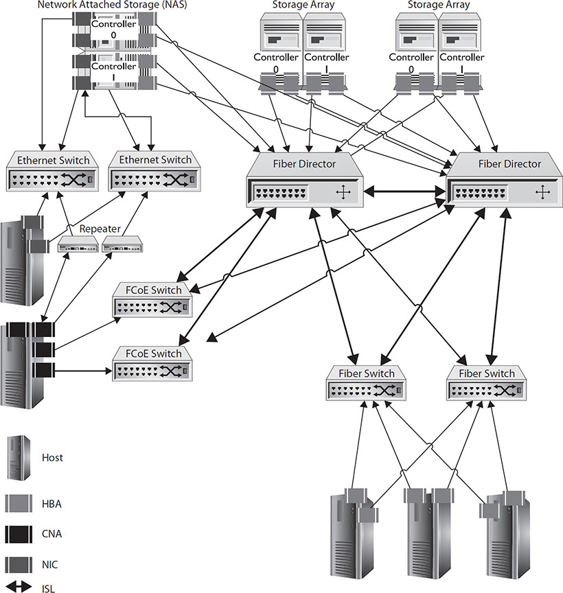
Figure 4-5 Storage networking devices
HBA
A host bus adapter is a device that connects a host to storage. The HBA processes I/O requests from the host and passes them to the storage. HBAs are equipped with one or more ports that provide a physical connection to storage such as copper or optical cables.
NIC
A network interface card (NIC) can be a form of HBA when it is used to connect to a storage resource, but it can also be used for communication with non-storage-related equipment such as servers or other hosts. The NIC provides the connection between a piece of equipment such as a server or storage device and the network. This will include a method for connecting to the equipment such as an interface for an internal slot such as PCI or PCIe, or it could be over USB; it will also include a port for connecting to the network such as RJ-45 for 100Base-T Ethernet.
Speeds
NICs are rated for the types of networks they can connect to, which also specifies the transmission speeds they support. The NIC will be labeled as follows: speed in megabits per second, baseband, or broadband, and the type of cabling. For example, 100Base-T is a baseband connection running at 100 Mbps over twisted-pair cabling, while 1000Base-X is a gigabit (1,000 Mbps) baseband connection running over fiber. T indicates twisted pair, and X indicates fiber.
TCP Offload Engine
The TCP Offload Engine (TOE) offloads the TCP/IP protocol processing to the network controller, alleviating the computer processor from having to perform this work. This can greatly decrease the impact high I/O network traffic has on the host system such as with the use of iSCSI or network file servers running NFS or CIFS. On average, each bit of TCP/IP data requires 1 Hz of processing power, so 500 Mbps of traffic would require 0.5 GHz of CPU time. As you can see, this is not an insignificant impact on the host system.
TOE performs the following tasks: synchronizations and acknowledgments, data verification through checksums and sequence numbers, congestion control, and connection establishment and termination.
CNA
A converged network adapter (CNA) is a multiprotocol adapter card that functions as both a NIC and an HBA. A single CNA can be used for FC, Ethernet, or twinax connections. CNAs perform onboard processing for FCoE, freeing up processor time for other tasks.
Repeaters and Amplifiers
A repeater rebroadcasts a digital signal over a cable. Repeaters can be used with optical or copper cables, and they must be installed at a point prior to the maximum distance of the cable so that the signal they receive can be correctly received and rebroadcast. Repeaters remove noise from the digital signal and then transmit the same signal that was sent at the source to the next repeater or the receiving node.
Amplifiers perform much the same role as a repeater for analog signals. The main difference, however, is that amplifiers cannot remove noise from the signal, so this is amplified along with the transmission. Analog signals do not attenuate as fast as digital signals, so fewer amplifiers are required to traverse the same distance.
Ethernet Switch
Ethernet switches are networking devices consisting of a group of RJ-45 ports for connecting twisted-pair cables in a physical star topology (see Chapter 3 for more information on topologies). Each port acts as a repeater as well, rebroadcasting the signal sent over it and extending the distance nodes can be separated by. The switch creates a dedicated connection between sending and receiving ports so that ports that are not part of the communication do not receive unnecessary traffic.
Switches will support a maximum bandwidth, meaning that while each port theoretically has full bandwidth, the overall bandwidth of the switch might be somewhat less than that. Table 4-4 lists the max speed supported by each Ethernet type. For example, a 48-port Gigabit Ethernet switch would be expected to have a bandwidth of 48 Gbps, but the vendor specifications may say that it has a bandwidth of 36 Gbps, so if all 48 ports were transmitting at the same time, the switch would not be able to give each port its full bandwidth.
Table 4-4 Ethernet Types

Two different types of switches have been made that forward frames differently. Cut-through switches read the destination address and then immediately forward the frame to the destination port, while store-and-forward switches buffer the entire frame and then determine where to forward it. Consequently, cut-through switches are faster than store-and-forward switches, and you would be hard-pressed to find a store-and-forward switch on the market today.
Ethernet switches typically have LED lights placed around the port to indicate connection type and activity. These LEDs can change color and blink. The colors may differ based on the manufacturer, but a green light typically means that the link is running at full duplex, and amber means it is running at half duplex when the display mode is set to duplex. If the display mode is set to STAT, then the green light typically indicates a link, and a blinking light means data is being transmitted.
Full-duplex communication allows data to be sent and received at the same time. Half-duplex communication must wait for a sending or receiving action to complete before another can take place. Blinking LEDs show that data is traversing over the link. Sometimes LEDs will be placed directly above ports, but in high-density switches, this may not be possible, so a separate section may have a large bank of LEDs labeled by port number. Port numbers typically start with 0, so a 48-port switch would have ports numbered from 0 to 47.
GBIC
Some Ethernet switches are equipped with Gigabit Interface Converter (GBIC) transceivers to allow for one or more fiber connections. Fiber connections are useful for connecting a wiring closet to the main facility. GBIC transceivers have electrical connectors on the end that connects to the switch and optical connectors on the end that connects to the fiber cable. GBIC can provide the switch with information on their capabilities and performance. GBIC port numbers are usually in addition to the port count on the switch, so a 48-port switch might have four GBIC ports as well. You should verify that all GBIC ports will work in addition to the 48 Ethernet ports because some vendors link the GBIC ports to other Ethernet ports; therefore, if the four GBIC ports are in use, ports 44–47 may be inoperable.
Fiber Hub
Fiber hubs are used with the Fibre Channel arbitrated loop (FC-AL) topology (see Chapter 3 for more information on topologies). Hubs act like a loop within the device, but nodes are connected to the hub like a switch, with each device having a cable from the device to the hub. The hub creates circuits between neighboring ports to form a ring. The transmit circuit from the upstream port is connected to the receive circuit of the downstream port. Inactive ports, such as those without a cable connected, are put into bypass mode through a feature called autobypass. Bypass mode skips the port and sends data to the next port. This increases the speed of the ring because it can reconfigure itself to be smaller when devices are removed or larger when they are added. Since fiber hubs are built for the FC-AL topology, they are not fabric capable, so they do not support fabric features such as Internet Storage Name Server (iSNS), registered state change notifications (RSCNs), security key distribution, or fabric logon.

NOTE Fiber hubs will allow you to create a larger network of devices, but remember that you cannot have more than 126 devices on an FC-AL network.
Fiber Hub Ports
Chapter 3 introduced the FC port types. As a reminder, fiber hubs use NL-ports to connect to FC-AL nodes and use FL-ports to connect to other fiber hubs. U-ports can be either an NL or an FL port, and it autosenses the type of port it is connected to in order to configure itself. There are some cases where autosensing does not work, and you will need to manually set the port configuration of a U-port to NL or FL on both sides for it to function. If you have cabled two fiber hubs together using U-ports and they are not communicating, check the port status on both sides to verify that each side has configured itself to be an FL-port and configure it manually if it is set to something else.
Fiber Switch
Fiber switches are networking devices consisting of a group of transceivers used for connecting fiber cables in a physical star topology (see Chapter 3 for more information on topologies). Fiber switches can be managed or unmanaged, but most of the models you will work with will be managed. Managed switches have an Ethernet interface that is used for web-based graphical user interface (GUI) or terminal-based command-line interface (CLI) administration of the switch. Some features of the managed switch include Simple Network Management Protocol (SNMP), firmware upgrades, centralized management of many switches from one console, and diagnostics. Windows or Linux servers can administer a managed switch by connecting to its IP address via HTTP for GUI management or Telnet or Secure Shell (SSH) for the CLI.
Fiber switches are capable of storing frames that cannot be delivered due to congestion on the link. This feature is known as buffering, and switches will measure their buffering capability in how many frames can be buffered. Modular switches have components that can be replaced if they fail. Some components such as power supplies may be hot-swappable, meaning they can be replaced without impacting the availability of the device. Other switches may be configured with banks of switch ports known as switch blades.
Low-end fabric switches may be configured with fixed fiber ports that will support only one type of fiber cabling and speed, but midrange and enterprise fabric switches use small form-factor pluggable transceivers.
SFP
Small form-factor pluggable (SFP) transceivers are used with fiber equipment. SFPs are used rather than building the transceiver directly onto the switch in order to support different types of media such as twinax, LC, SC, or ST connectors. SFPs also make the base switch cheaper to build, and companies can add SFPs as needed.
Fiber Switch Ports
Port types were introduced in Chapter 3, and they need to be mentioned once again in this discussion on switches. Please remember that fiber switches use F-ports to connect to FC-AL nodes and use E-ports to connect to other switches. G-ports can be either an F or E port, and the port will autosense the type of port it is connected to in order to configure itself. Similar to the U-ports on fiber hubs, there are some cases where G-port autosensing does not work and you will need to manually set the port configuration to F or E on both sides for it to function. If you have cabled two fiber hubs together using G-ports and they are not communicating, check the port status on both sides to verify that each side has configured itself to be an E-port and configure it manually if it is set to something else. If you plugged a node into a G-port, make sure the G-port has configured itself as an F-port.
Director
Fiber directors are high-capacity modular switches that can have upward of 500 ports, usually through the use of switch blades that plug into a backplane on the director. Directors have two or more hot-swappable power supplies and redundant routing engines, pathways, and processors in the backplane to better prevent against failures. Directors may be used in the fabric core to ensure that core services have the highest redundancy. They may also be used to connect storage arrays to the fabric because of the need of storage arrays to be highly available. It would most likely cost an organization much more if a storage array were unavailable than if a single host were unavailable, so a higher priority for redundant components is given to storage arrays. When choosing a director, check to see how the modules connect. Cheaper directors may connect switch blades together with an internal ISL or ISL port channel. This will significantly limit the bandwidth available between switch blades, and it will create another hop between devices on different blades, which will reduce the number of switches that can be attached to the fabric.
Router
A router operates much like a switch, but it has a higher-level understanding of the data that passes through it. A router can differentiate between traffic from different networks so that data can be passed to the appropriate destination. Routers maintain a routing table that provides information on how to get to other networks. Various routing protocols such as Routing Information Protocol (RIP), Open Shortest Path First (OSPF), Border Gateway Protocol (BGP), and Enhanced Interior Gateway Routing Protocol (EIGRP) can be used by routers to share information on the networks they service. These routing tables are updated as links go down so that the routers in a network can send data along alternative paths. Routers determine the required hop counts or number of nodes a packet would need to traverse in a route to reach a destination. Routers will use the route with the lowest hop count unless that route becomes unavailable. This makes routers efficient for delivering data but also resilient against link failures.
Hot-Swappable Network Components
Many network components can be hot-swapped in compatible devices. For example, fiber switches or directors may include hot-swappable power supplies, banks of ports, or control boards, and SFP and GBIC are hot-swappable. Hot-swappable components can be replaced while the system is online. If a hot-swappable component fails or needs to be changed, it can be done without shutting down the device. Once the new device is inserted, the network device will recognize that it has been inserted, and storage administrators can then configure it.
Before moving on to removable storage, you may want to revisit Figure 4-5 showing how all these devices, directors, routers, switches, repeaters, HBAs, CNAs, and NICs work together.
Removable Storage
Sometimes it is important to be able to move or copy data to another location physically. The most common use of removable storage is for archiving. For example, a company may copy data onto backup tapes that can be taken offsite. If systems are destroyed at the primary site because of an incident such as a fire, the offsite tapes can be used to restore the data and bring the systems back online. Consumers and companies utilize removable storage such as USB hard drives, flash drives, or DVDs to archive data in the case of accidental deletion, corruption, or loss, so it is important for storage administrators to understand the types of removable storage hardware available and commonly in use.
Tape Media
Tapes are an efficient method for writing sequential data to a removable media and are especially well suited for backups and archiving. Tape media is relatively inexpensive compared to nearline and online storage technologies such as hard drives. Backup tapes are made up of two spools, one of which is wound with a strip made of plastic and coated with a magnetic material. Tape media is read by tape drives. Tape drives slide open an access port on the tape and advance the magnetic strip across the access port to read or write data. The second spool receives the strip that has passed by the access port. A read-write head in the tape drive can use a magnetic field to create patterns in the magnetic material on the tape, or it can read the patterns that have been placed on it before.
Tape drives read and write data sequentially. When reading data in the middle of a tape, the drive will fast-forward the tape to the desired location and then read the data. This is efficient for data that is located in adjacent areas, but inefficient for data scattered throughout the tape.
There are many cases where tapes are not the best option, and that is because tape media suffers from several limitations. First, accessing random data from a tape takes an average of 50 seconds, an extremely long time in computer terms, because the tape has to fast-forward or reverse to put the read-write head in position to read the data. The situation is one you are likely familiar with if you have listened to both cassette tapes and compact discs. If you want to find a specific song on a compact disc, you simply skip to the track number, but on a cassette tape, you have to fast-forward or rewind to the appropriate part and you must listen and wait until you get there.
Second, the reading and writing process causes much more stress to a tape than a hard drive. The read-write head makes physical contact with the tape each time data is read or written, which wears out the tape. The average tape can be written to fully about 200 times or have no more than 5,000 cartridge loads and unloads. This means that daily tapes should be replaced every six months and weekly tapes every four years. Even tapes used purely for archival purposes should be replaced every 15 years because their archival life span is between 15 and 30 years; the general rule is to replace monthly and yearly tapes every 15 years to be safe. The replacement process when data must be preserved involves reading the data from the tape and then writing it back to a new tape. To refresh old tapes and to be able to recover data from old tapes, organizations may need to keep antiquated hardware around.
Particles can build up on tape heads, so they must be periodically cleaned. Unreadable data may be written to tape if the drive is not cleaned regularly. Fortunately, many tape libraries are equipped with sensors that can detect when a drive must be cleaned, and a cleaning tape can be permanently loaded in the library so that cleaning operations will take place automatically. This removes the risk of a loss of data integrity because of a backup operator’s lack of diligence in tape cleaning. Finally, tape drives can service only one request at a time, so they are ill suited as a shared medium.
Multistreaming and Multiplexing
Multistreaming allows a backup job to be sent to multiple I/O devices such as tapes or virtual tape library (VTL) stores (see Chapter 5 for information on VTL). This is especially useful for large backups that would take an extremely long time to write to a single tape, but the recovery process may require multiple tapes to be inserted.
Multiplexing is a method for writing multiple backups at the same time to a backup tape. This can save time, and it ensures that the stream of data to the tape remains full; however, it comes at a disadvantage when recovering backups because the data associated with a single backup is fragmented on the tape, so the drive will end up reading some data and then fast-forwarding ahead to the next point where that data was written.
Shoe Shining/Backhitching
Tapes can also suffer from shoe shining, sometimes called backhitching, a condition where the device sending data to the tape does not send data fast enough so the tape has to repeatedly stop and rewind to put itself back into position to write the next chunk of data in sequence. This causes strain on the tape and decreases its life expectancy.
LTO Versions
Linear Tape-Open (LTO) is a magnetic tape standardization for use in data storage to replace Quantum’s Data Linear Tape (DLT) and Sony’s Advanced Intelligent Tape (AIT). The LTO consortium was started by HP, IBM, and Seagate so that rather than dealing with different vendor offerings, vendors could operate off a single standard. Its first version, LTO version 1 or Ultrium, was a tape that could hold 100GB. Table 4-5 provides the specifications for the different versions of LTO.
Table 4-5 LTO Specifications

LTO tapes must be rewound once data has been written to them. This adds approximately 80 seconds to the tape operation if the tape must be completely rewound.
Compression and Encryption
LTO compression and encryption can be implemented in hardware or software. Hardware implementations are generally faster since they eliminate the operating system processing overhead required to perform compression or encryption calculations.
Table 4-6 provides the compression and encryption specifications for each LTO type. LTO versions 1 through 5 used the Adaptive Lossless Data Compression (ALDC) method, and LTO6 uses Streaming Lossless Data Compression (SLDC). ALDC achieves a compression ratio of 2 to 1 and has been used in versions of LTO1 through LTO5. However, some data that is compressed by ALDC is actually larger than the source data when it has been compressed already with another algorithm. SLDC solves this problem by comparing the compressed size using SLDC to the size of the data without SLDC and then writing the smaller of the two. SLDC achieves a compression ratio of 2.5 to 1 and is used in LTO6.
Table 4-6 LTO Compression and Encryption

LTO4 through LTO6 tapes can be encrypted using a symmetric version of the Advanced Encryption Standard (AES) that encrypts and decrypts with the same key. The encryption can be handled by the LTO drive and does not require additional software to implement.
Size vs. Speed
Data sets typically get larger rather than smaller over time, so backup strategies must be scalable. One option is to extend backups onto multiple tapes as they grow. This will increase capacity, but it will take much longer to write the backup job. Speed can be increased by adding more drives and splitting the data among the drives through backup partitions or through multistreaming. In some cases, it may be advantageous to upgrade to a newer version of LTO. The capacity of the tapes doubled between LTO specifications 1, 2, 3, and 4, and read-write speed doubled between specifications 1, 2, and 3; therefore, tape users who moved from LTO1 to LTO2 or from LTO2 to LTO3 could store twice as much data on the tape because of its double capacity, but the write operation took the same amount of time (see Table 4-4).
Tape Care
Follow these guidelines to protect backup tapes and the data they contain. The access door that covers the tape keeps foreign particles such as dirt and dust from entering the tape cartridge. Avoid opening the access door unless absolutely required for servicing. Do not touch the magnetic strip inside the tape cartridge because this can destroy data on the tape and leave residue from your fingers that can harm the read-write heads in tape drives. Place barcode labels straight in the space provided on the edge of tapes to avoid barcode read errors in tape autoloaders and libraries. Discard tapes that repeatedly show read-write errors.
Clean tape drives as needed and keep track of the number of times tape-cleaning media is used so that it can be replaced when necessary. Tape-cleaning media can be used only a certain number of times before it becomes ineffective, potentially doing more harm than good. The number of cleanings will be documented in the cleaning-tape packaging and many times on the cleaning tape itself. Store tape drives and tape media away from printers and other devices that produce dust and other contaminants.
Tapes should be stored in an environment that is kept between 41 degrees and 90 degrees Fahrenheit with a relative humidity between 20 and 60 percent. When transporting tapes, it is best to use a carrier designed for the type of tape you are using. These cases will have inserts for tapes and have plenty of padding to protect against bumps or drops. Some cases can be locked for additional security if necessary.
LTFS
Linear Tape File System (LTFS) is an Extensible Markup Language (XML)–based tape file system that allows for tape resources to be accessed much like a mounted drive. Prior to LTFS, file metadata including filenames was stored in a database, catalog, or index maintained by the backup software, so the backup software was necessary to access files and directories on the tapes. With LTFS, files and directories on the tape can be viewed within the operating system itself without the need for backup software, and files can be added, opened, or removed directly without the use of specialized backup software as long as the operating system supports LTFS. Currently, LTFS is supported on LTO5 and LTO6 tapes and the following operating systems:
• Microsoft Windows 7
• Microsoft Windows 8
• Microsoft Windows Server 2008 R2
• Microsoft Windows Server 2012
• Mac OSX 10.5.6 Leopard and newer versions
• Red Hat Enterprise Linux 5.4 and newer versions
• SUSE Linux Enterprise Server 11 SP1 and newer versions
Please note that while LTFS tapes allow for file deletion, deletions only mark the blocks where deleted files reside as unavailable. These blocks are not free to use for storing other files, so it is not possible to delete a large amount of data from the LTFS tape through the operating system in order to add different data to the tape because the deletion would not actually free up space.
NDMP
Network Data Management Protocol (NDMP) is a method for transferring backup data directly between devices on a storage area network such as a storage array and a tape library. This allows for less overhead for backup operations since a server is not required to manage the backup jobs and interface between the storage array and the backup device. NDMP backups are known as an in-band solution since communication occurs entirely within the storage network. NDMP is especially valuable for network attached storage (NAS) since the backups can occur in-band on the storage network rather than over the data network. This results in less impact to the performance of the NAS during backups. NDMP is an industry standard that is supported by many vendors, so equipment from different vendors can work together using this protocol.
Libraries and Autoloaders
Organizations may end up managing hundreds if not thousands of tapes in the course of backing up data. Libraries and autoloaders make the job of managing and changing tapes easier. Tape libraries, sometimes called tape jukeboxes or active tape libraries (ATLs), are devices that can hold many tapes in slots known as magazines along with several drives. Multiple-drive units can write data to multiple tapes concurrently. A robotic arm moves tapes from the magazines to drives and then back into magazines when read or write operations complete. Tape barcodes are used to identify tapes to the library. Stackable tape libraries allow for additional shelves to be placed above or underneath the main library unit to provide more tape magazines. Tape autoloaders are a smaller version of a tape library that contains only one drive, but it may contain one or more magazines with many tapes. Tape libraries and autoloaders come equipped with interfaces such as FC, SAS, or SCSI to connect to a storage network or to a host. Those that use NDMP should be connected to the storage fabric directly rather than through a host.
Optical Media
The technology behind optical media began with the LaserDisc. LaserDisc technology was created in 1958 and first used for the storage of video in 1968. The LaserDisc format, the highest-quality video available from 1978 until the release of DVD, was born as a two-sided, 12-inch-diameter optical disc made of aluminum covered in plastic with a label in the center. LaserDisc was primarily a video format, but it was also used for mass data storage, although this was rather rare. LaserDisc technology was adapted to be used in audio in 1982 as the compact disc format, and compact discs were eventually used for data storage with the release of the Compact Disc Read-Only Media (CD-ROM). As technology improved, the CD was replaced by the Digital Video Disc (DVD), which, in turn, was replaced by Blu-ray Disc.
These optical formats, LaserDisc excluded, each share some of the same technologies such as the ability to write data to discs in a process known as burning, use of buffer cache, and their use of pits and lands to represent binary 0s and 1s.
A large number of optical discs can be stored in a jukebox. Jukeboxes have been made for LaserDiscs, CDs, DVDs, and Blu-ray Discs. Jukeboxes keep track of the discs they house and will load a disc on demand similar to a tape library. Some jukeboxes are available for writing data to discs. These devices can take a large amount of data that spans many discs and write it out to discs sequentially with one or more CD, DVD, or Blu-ray burners. Technology such as LightScribe allows these jukeboxes to create a descriptive label for completed discs. These devices often are equipped with software to allow multiple network users to submit data to the device. Administrators can view and manage job queues, manage access to the device, and run reports.
Most optical media are write-once, read-many (WORM) media. Once they are pressed at the factory, the data cannot be changed on the disc. Naturally, scratches and smudges can make portions of a disc or an entire disc unreadable, but users cannot write new data to a disc or other WORM media as they could with a hard disk drive. Once WORM media has been written to, there is a reasonable assumption that the data has not been altered, so WORM is an effective way to prevent changes to stored data.
Burning
Disc burning technologies have come in many formats such as CD-R, CD-RW, CD+R, CD+RW, DVD-R, DVD-RW, DVD+R, DVD+RW, DVD+R DL, DVD-R DL, DVD-RAM, BD-R, BD-RE, BD-R DL, and BD-RE DL; these technologies can be easily organized into one of two feature offerings. One type can write data to a blank disc, and then the disc cannot be written to again. The second, rewritable technology allows for discs to be written to and erased over and over again.
Burning processes originally required the recorder to write continuously without disruption. If the burning process was disrupted, the disc would become worthless. 1Disc burners use a buffer to stage information about to be written to disc, but if this buffer is emptied, the process will become disrupted. This is known as buffer underrun. I used to make sure that all other programs were closed, and I would not use my computer while burning to guard against failed burns. Manufacturers introduced buffer underrun protection technologies such as BURN-proof, Safeburn, and Power Burn, and the problem of buffer underrun was soon resolved.
There are three formats for data writing: disc at once, track at once, and packet writing. Disc at once writes all the data to the disc without any gaps and then closes the disc. Closing the disc makes it so that no more data can be written to the disc. Track at once writes the data to the disc but leaves the disc open so that more data can be added to it later. Packet writing leaves the disc open and allows for data to be deleted or modified on the disc. Deleting data, however, does not free up space because the data still exists on the disc but is inaccessible.
Overburning is a process of burning data to a disc past the normal limits. Overburning can add data to the disc at the risk of making the disc unreadable by some or all players. Overburning can also damage the CD, DVD, or BD writer, so it should be avoided.
Compact Disc
The compact disc (CD) was the first format to see widespread use for data storage. A CD is 4.72 inches in diameter and made of aluminum and plastic. The aluminum contains the data as a series of pits organized into tracks on the disc. The plastic covers the bottom of the disc and protects the aluminum. A label is placed on the top of the disc, and the data is read from the bottom.
A laser with a beam size of 780nm shines on the disc to read it. The beam will either strongly reflect back or refract, which indicates whether the laser passed over a pit or land (areas without pits). A data table is stored at the beginning of the disc so that data can be located efficiently. A standard CD holds 74 minutes of audio or 682MB of data. Newer discs can hold 80 minutes of audio or 700MB of data; 734–842MB can be stored on discs when overburning is used, but these discs may not be compatible with all players, and overburning could ruin the CD burner.
The life span of burned CDs can vary greatly depending on the dye used in creating the CD-R. Cheaper dyes such as Cyanine may last only a few years, while gold can last around 100 years. As you can expect, few CDs are made with gold, and many use a combination of azo, phthalocyanine, or cyanine, which may give them a life span of 10 to 40 years. Factory-pressed CDs, however, can last more than 100 years.
CD-ROM data transfer speeds are rated in multiples of a single speed, which is 153,600 bps. For example, 2x reads at 307,200 bps. The remaining speeds are listed in Table 4-7 along with access time and rotations per minute (RPM). The access time, similar to HDD access time, is the average amount of time it takes to begin reading data; lower access times are preferred.
Table 4-7 CD Transfer Speeds

CD burning takes place at different speeds similar to the way data is accessed on a device. Table 4-8 lists the speeds, their transfer rate, and the time to write an entire CD.
Table 4-8 CD Burning Speeds

DVD
The digital video disc (DVD) was introduced in 1995 where it soon offered companies and consumers a higher-capacity option for data storage over CD. Single-layer DVDs can hold 4.37GB, and dual-layer DVDs can hold 7.96GB. That’s more than six times the capacity of a CD for single layer and eleven times a CD’s capacity for dual-layer DVD. DVDs are the same size as a CD, but the data is stored using smaller pits on the disc. A more precise 650nm laser reads the data in much the same way as a CD is read. A burned DVD has a life span of approximately 45 years, a burned DVD rewritable has a life span of 30 years, and a factory-pressed DVD can last for more than 100 years.
Blu-ray Disc
The successor to DVD is the Blu-ray Disc (BD). It was released in 2006 along with a competing product called HD-DVD. While single-layer BD can store 25GB as compared to 30GB with HD-DVD, HD-DVD can have only a single layer. Dual-layer BD can store 50GB, triple-layer BD can store 100GB, and quad-layer BD can store 128GB. This, among other factors, eventually won Blu-ray Disc’s dominance over the market. Blu-ray gets its name from the blue color spectrum (405nm) of the laser used in reading and writing to Blu-ray Discs. Prior to BD, red lasers such as the 650nm (DVD) and 780nm (CD and LaserDisc) were used because of their low cost, but these lasers were limited in how precise they could be. Innovation in crystal manufacturing made the blue laser more cost effective to produce and led to the introduction of BD.
ISO
Images of CDs, DVDs, and BDs can be created in a format known as ISO. The name was derived from the ISO 9660 specification for the CD file system, and it is also the three-letter extension used for the image file. ISOs allow for disc images to be loaded into a virtual optical drive so that software can interface with data on a CD just as it would if the disc were in a drive. Many manufacturers are distributing software as ISO downloads rather than packaging CDs or DVDs with their products. This is especially valuable for virtual servers or virtual storage appliances that may not have a physical optical drive assigned to them. In these cases, an ISO file can be mounted in the virtual device so that it can reference the data on the imaged optical disc.
File Systems
Optical media, just like hard drives, standardize the way data is stored and tracked through the use of a file system. The two main file systems in use for optical media are CDFS and UDF. BDFS is also discussed here, but it was used only briefly for Blu-ray Discs.
The Compact Disc File System (CDFS), specified in ISO 9660, allows access to data stored on a CD in tracks and sectors, each 2,352 bytes long. After error correction and header information, each sector can hold 2,048 bytes. CDFS allows for directory structures to be eight levels deep, including the root directory. For example, this directory would be the maximum allowed on CDFS: dataaccountingusalaskaanchorage2004january. This may require some directory structures to be revised prior to being written to CD. CDFS also supports a maximum of 65,535 directories because of its 16-bit path table.
The Universal Disc Format (UDF), specified in ISO 13346, replaced CDFS, and it is used mainly on DVDs and some BDs. UFS allows for a maximum filename length of 255 bytes and a maximum path name length of 1,023 bytes.
Blu-ray Disc File System (BDFS) maintains a database of data allocations on the Blu-ray Disc that takes up a few megabytes in a section of the disc allocated for system management information. It is efficient for storing video streams, but it was used only for a short time. It was replaced with UDF 2.5 in order to make it easier for computers and other systems that already understood UDF to operate with BD.
Flash Media
Similar to the solid-state disks (SSDs) discussed in Chapter 1, flash media utilize Negated AND (NAND) flash memory to store data. Flash media forms the basis of today’s sneakernet, allowing individuals to easily copy data to a portable device. Flash media is also used in many mobile devices such as digital cameras, digital camcorders, MP3 players, phones, and tablets. Flash media is either used as built-in storage or via add-in cards such as Secure Digital (SD), Multimedia Card (MMC), CompactFlash (CF), and others, as shown in Table 4-9. Its popularity stems from the fact that it can be constructed in various small sizes and it uses relatively little power. Most offerings allow for approximately 1 million write cycles, which is ten times that of an SLC SSD drive.
Table 4-9 Flash-Based Add-in Cards

NOTE Sneakernet is an old term that referred to a network where data was transferred when people carried floppy disks from one computer to another. The data was carried by “sneakers,” aka their feet.
Flash media is also commonly equipped with a USB interface. Once connected to a computer, these flash drives can be accessed like any other local hard drive, making it easy for users to archive data, add capacity, or share data. The size of USB flash drives continues to increase, and their size remains small enough that they could be attached to a keychain or stored easily in a pocket.
Chapter Summary
This chapter covered storage hardware beginning with optical and copper cables. Optical cables transmit data using light that is directed through a glass core surrounded by a protective cladding. Optical cables are well suited for long-distance applications, high-bandwidth connections, and communications through areas with interference. Optical cables are more expensive than copper, and the hardware used to interface with them is also more expensive. There are two types of optical cables: single-mode fiber (SMF) and multimode fiber (MMF). Single-mode fiber can span greater distances using a small precision core and a laser, whereas MMF uses an LED and a larger core but can transmit more data over shorter distances.
Optical cables connect to other networking devices by using connectors such as the standard connector (SC), local connector (LC), and straight tip (ST). SC and LC have dual connectors bound together for sending and receiving, and their ends are roughly square-shaped. LC is the smaller of the two, allowing for higher density in switching.
Care must be taken to not bend or place stress on optical cables to avoid connection loss or cable damage. Cables should be installed in runways through data centers or pipes in the ground to protect them.
Copper cables use electromagnetic waves to transmit information. Copper is cheaper than optical cable, but it cannot span long distances and is limited in data rate. Copper cables are not as fragile as optical cables, but they must still be cared for. Twisted-pair cabling is most vulnerable to damage through stretching.
• Twisted-pair cabling is the most common copper cable used in computer networking. Twisted-pair cables are defined by category (Cat); they are ranked from 1 to 6, with 6a being the newest.
• Serial cables are used mainly to connect to management consoles on storage networking and computer networking hardware such as fiber switches, routers, and Ethernet switches.
• Twinax cable can support up to 10 Gbps speeds, and it is often used to connect storage devices to a switch as an alternative to fiber connections.
Cables carry data from one place to another, but they cannot act alone. Devices are required to store and transmit data at intermediate points and to send and receive data at end points. End points need to be equipped with a host bus adapter, network interface card, or converged network adapter to interface with cables.
NICs are mostly used with Ethernet networks, including some iSCSI implementations, while HBAs are used for most other connections such as FC or iSCSI.
The CNA can support multiple protocols and is mainly used in FCoE implementations.
Repeaters and amplifiers can be used to simply rebroadcast the signal and extend the range of the cable run, and switches, directors, and routers not only repeat the signal, but also send the signal to other cable segments that ultimately lead to the destination.
This chapter’s last section provided information on removable storage, including tapes, optical discs, and flash drives.
• Tapes are a low-cost method of writing sequential data and are mainly used for backups.
• Optical discs are a low-cost way of archiving and distributing information. Data is written to optical discs through a process called burning where a laser burns pits into the disc.
• Flash media takes the form of small cards that can be placed in devices such as phones or cameras or built into these devices.
Chapter Review Questions
1. Which technology would aid in reducing the processing load on a host system?
A. Amplifier
B. GBIC
C. TOE
D. SFP
2. You notice that a tape backup is quite noisy. As you investigate, you find that the tape repeatedly stops and rewinds during backup operations. What is the cause of this?
A. Random reads from tape
B. Backhitching
C. LTO version incompatibility
D. Multistreaming
3. A co-worker tells you that you don’t need Cat6a because Cat6 supports 10GigE. What is the limitation of using Cat6 instead of Cat6a?
A. Cat6 must be shielded to protect against EMI.
B. Cat6 supports only 10GigE using 10GBASE-RF.
C. Cat6 cannot coexist with Cat5/Cat5e cables.
D. 10GigE over Cat6 is limited to only 55 meters.
4. Your company is installing a fiber link between its headquarters and an office 15 miles away. You plan to do SAN replication over the fiber link. Which cable would you use for the link between sites?
A. 9/125
B. 50/125
C. 62/125
D. 100/125
5. A junior team member has been assigned the task of patching Ethernet cable for a new 10 Gbps iSCSI network to a 10GigE switch, but he is unsure about how to wire the cable. What should you tell him? Each cable will be no longer than 12 feet.
A. Use Cat5 and wire it with EIA/TIA 568A on both ends.
B. Use Cat5 and wire it with EIA/TIA 568A on one end and 568B on the other end.
C. Use Cat6 and wire it with EIA/TIA 568A on both ends.
D. Use Cat6 and wire it with EIA/TIA 568A on one end and 568B on the other end.
6. A storage server writes out approximately 900MB of new encryption keys each month that need to be archived. Data integrity is important, so users should not be able to modify the data once it has been archived. Which solution would be best in this situation?
A. Burn the keys to a CD-R each month.
B. Create a job that automatically writes the keys to a backup tape each month.
C. Burn the keys to a DVD-R each month.
D. Create a script that replicates the keys to a network share that users have read-only access to.
7. You have purchased a new fiber switch, and you would like to connect several servers and a storage device to it. You purchased fiber cables with LC connectors, and the servers and storage devices are all equipped with fiber HBAs with LC connectors. What other hardware is required for the network to function?
A. CNA
B. GBIC
C. Fiber management software
D. SFP
8. The server administration team has configured a new database server that must attach to the storage area network. They have purchased it with a fiber HBA that is equipped with dual LC fiber ports. You have a box of fiber cables. One cable is green with two large square ends. Another is orange with two smaller square ends, and the third is round with a bayonet plug. Which one should you use to connect the HBA to the network?
A. The cable with the large square connector.
B. The cable with the small square connector.
C. The cable with the round connector.
D. The cable is not present in the box.
Chapter Review Answers
1. C is correct. The TCP Offload Engine (TOE) offloads the TCP/IP protocol processing to the network controller, alleviating the computer processor from having to perform this work.
A, B, and D are incorrect. An amplifier rebroadcasts a signal. Both the GBIC and SFP are transceivers that interface between a network device and a cable.
2. B is correct. Backhitching, also called shoe shining, is a condition where the device sending data to the tape does not send data fast enough, so the tape has to repeatedly stop and rewind to put itself back into position to write the next chunk of data in sequence.
A, C, and D are incorrect. A is incorrect because backup operations are serial and do not result in random reads or writes. Also, a backup operation is a series of writes, not reads. C is incorrect because if the LTO version was incompatible, the backup would not run to the media at all. D is incorrect because multistreaming would result in better performance but would still be serial operation and not result in stops or rewinds.
3. D is correct. Cat6 can transmit at 10 Gbps, but it is limited to 55 meters when doing so. Cat6a can go 100 meters while transmitting at 10 Gbps.
A, B, and C are incorrect. A is incorrect because Cat6 does not require additional shielding to perform at 10 Gbps. The twisted pairs in the cable are used to protect against internal interference, and interference results in loss of connectivity, not reduced speed. B is incorrect because Cat6 can be used with any supported 10GBASE standard to achieve speeds of 10 Gbps. C is incorrect because Cat6 and Cat5 can coexist on the same network, and even the same switch, but each cable is limited to their own maximum speed.
4. A is correct. First the question asks which cable is needed to run a distance of 15 miles. Of the two main types of optical cables, SMF can span thousands of kilometers, and MMF can reach only a maximum of 2 kilometers, so you will need to use an SMF cable. The answers provided are cable types given using the core/cladding description. The first number is the size of the core in microns, and the second number is the size of the cladding. If the core is less than 10, it is SMF, and if it is between 50 and 100, it is MMF. Option A, 9/125, is an SMF cable, so A is the answer.
B, C, and D are incorrect. B, C, and D are all between 50 and 100, so they are MMF cables and can only reach a maximum of 2 kilometers, so they will not meet the requirements.
5. C is correct. Cat6 will provide the required 10 Gbps speed, and the same EIA/TIA specification must be used on both ends to connect to the switch. A, B, and D are incorrect. The iSCSI network will run at 10 Gbps, so the team member will need to use Cat6 or Cat6a. This eliminates options A and B. Of the two remaining choices, one uses a different specification for each end, and the other uses the same. Normal cables use the same specification for both ends. Only crossover cables use a combination of 568A and 568B, so C is the correct answer.
6. C is correct. The files must not be changed, so the option should be read-only, and a DVD would be required since a DVD can store more than 4GB of data. A, B, and D are incorrect. The files must not be changed, so the option should be read-only. The read-only share in option D would not work because local users on the server could have access to modify the data. Option B writes the data to tape, but this could be erased or modified. Options A and C burn to optical media. Once the media has been written to, it cannot be altered. However, a CD does not have enough space to store 900MB, so a DVD would be required since a DVD can store more than 4GB of data.
7. D is correct. A transceiver is necessary to accept the light signal and convert it to an electrical impulse the switch can understand. Fiber switches uses SFPs, and an SFP is required for each port that will have a fiber connection. Fiber switches ship without SFPs so that customers can purchase the appropriate SFP for their network. In this case, an SFP with an LC connector would be needed. A, B, and C are incorrect. A CNA is used for FCIP networks and would not be used in this situation. A GBIC is not used with fiber HBAs, so it is incorrect, and fiber management software is not a hardware solution.
8. B is correct. The HBA has LC ports and so you must use the LC connector. LC connectors are small with two square ends. A, C, and D are incorrect. A is incorrect because a cable with two large square ends describes the SC connector, and C is incorrect because round bayonet plugs are found on ST connectors. D is incorrect because the correct cable is in the box; it is the LC connector.