
Hardware
Domain Objectives
• 3.1 Explain basic cable types and their connectors, features, and purposes.
• 3.2 Given a scenario, install the appropriate RAM.
• 3.3 Given a scenario, select and install storage devices.
• 3.4 Given a scenario, install and configure motherboards, central processing units (CPUs), and add-on cards.
• 3.5 Given a scenario, install or replace the appropriate power supply.
• 3.6 Given a scenario, deploy and configure multifunction devices/printers and settings.
• 3.7 Given a scenario, install and replace printer consumables.
 Explain basic cable types and their connectors, features, and purposes
Cabling and wiring are the primary media for connecting circuits, printed circuit boards (PCBs), expansion slots, components, peripheral devices, and even other computers. Cables (and wires) are extremely important to a computing device’s internal communications and, to a lesser degree, to its external communications with other devices. In this objective, we look at the various types of connection media, connector devices, and their use.
Network Cables and Connectors
Network cables interconnect computers and other devices on wired networks, primarily LANs, as well as provide a connection to an Internet gateway. There are three primary categories of network cables, each based on its core material:
• Twisted pair (TP) This copper multiple-wire cable is the most used cable for Ethernet LANs and telephone connections.
• Coaxial This cable type has a solid copper core and a metallic shielding for the transmission of cable TV and Internet services.
• Fiber optic This cable type transmits a light stream over a glass or plastic strand. Fiber cabling can be used for LAN connections, but it’s more commonly used for long-haul transmission in WANs.

NOTE Another very popular LAN medium is RF signaling, more commonly known as wireless networking, WLAN, or simply Wi-Fi. Domain 2.0 of the Core 1 exam (220-1101) covers wireless media.

EXAM TIP Be sure you are familiar with the network cable types identified in this objective and their speeds, characteristics, and any transmission limitations.
Copper Cables
Wired Ethernet networks were first interconnected (and continue to be) using copper-core wiring and cable. As defined earlier, the two primary types of copper cabling are twisted pair and coaxial cables. Of these two cable types, TP is by far the more commonly used with coaxial cabling used in special situations and for special purposes.
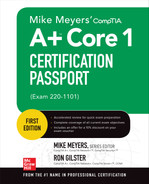
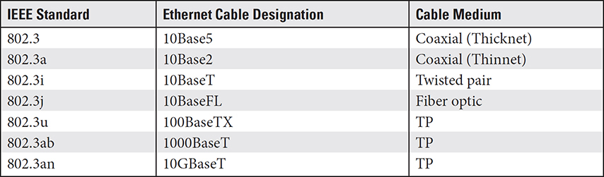
TP cable, as shown in Figure 3.1-1, is composed of eight solid or stranded copper wires arranged in four color-coded pairs. Table 3.1-1 compares the characteristics of the major categories of Ethernet cable in current use: Cat 5, Cat 5e, Cat 6, and Cat 6a.

FIGURE 3.1-1 A Cat 6 twisted-pair cable
TABLE 3.1-1 Common Ethernet Cable Types
NOTE The Electronics Industry Association/Telecommunications Industry Association (EIA/TIA) classifies twisted-pair cable into categories, or Cats, each of which defines the construction, characteristics, and proper use of different twisted-pair cable types, such as the number of wires and nominal transmission speeds. Cats 1 through 4 are now considered to be defunct, and Cats 7 and 8 (40 Gbps) are now available.
EXAM TIP Although most Ethernet installations use twisted-pair cabling, Ethernet networks can also use fiber optic or coaxial cable. Coaxial cable is still in use for hazardous environments, such as wet areas.
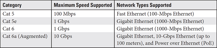
TP cabling used for Ethernet networks is also designated by the IEEE 802.3 standards with a more descriptive coding system, referred to only as the Ethernet standard. Table 3.1-2 lists the more commonly used of the Ethernet cable codes. As shown, the cable designations include three components: a data transfer speed, a transmission mode, and a medium designation. For example, a 10BaseT designation translates to 10 Mbps speed, baseband transmission, and twisted-pair medium.
TABLE 3.1-2 Common 802.3 Ethernet Cable Codes
EXAM TIP For the A+ Core 1 exam, you should know the IEEE standards in Table 3.1-2. The Ethernet standards in this table are for informational and cross-referencing purposes only.
Unshielded Twisted Pair
Unshielded twisted pair (UTP) cabling consists of four to eight 22–26 AWG (gauge) insulated wires, each of which is twisted with a color-matched wire mate into a wire pair. The resulting four pairs are then enclosed in a common protective sheathing. The EIA/TIA 568 standards, which the A+ exam refers to as T568A and T568B, specify the pattern and sequence of the color-coded wires. UTP cabling is the most common cable type used for Ethernet local area networks. Figure 3.1-1 shows the construction of a Cat 6 UTP cable.
The twisting in each wire pair is done to diminish electromagnetic radiation between the wires in the pair and the crosstalk with adjacent wire pairs. In addition, the twisted wire pairs also help to reject electromagnetic interference (EMI) from outside the cable. Not that you really need to know this, but Alexander Graham Bell developed this concept.
Shielded Twisted Pair
Essentially, a shielded twisted pair (STP) cable has the same basic construction as a UTP cable. However, each wire pair is wrapped in a foil shielding to further increase its rejection of external EMI. STP is not frequently used in general network installations. It’s more commonly used in EMI-heavy settings, such as a machine shop floor or any area with electric motors.
Most Ethernet cables are marked with a Cat number, as shown in Figure 3.1-2.
FIGURE 3.1-2 Cat 6 cable showing the identification on the sheathing
The EIA/TIA 568 standard, discussed later, sets the maximum distance for a single Cat 5, 5e, or 6 cable run (between two network devices). For Cat 5, Cat 5e, and Cat 6a, the maximum segment length is 100 meters (about 328 feet). This distance represents the attenuation point for each cable type. Cat 6 has a max distance of 55 meters (a bit more than 60 feet). Beyond these distances, a network repeater may be used to initialize a new cable segment, extending the attenuation point of the cable.
Cat 6a (Cat 6 augmented) is a version of a shielded TP that provides some additional protection for its transmission wires. As shown in Figure 3.1-3, its outside sheathing material is a low-smoke nontoxic material, with its internal wire pairs foil-wrapped and each wire protected as well.
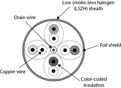
FIGURE 3.1-3 A cross-section of a Cat 6 cable showing its construction
Cross-Reference
To learn more about network devices used with Ethernet, see Domain 2.0, Objective 2.2.
Direct-Burial Underground Cable
Should it be necessary to cross an open space, you may be required to (or desire to) install a network cable underground. As it seems to be for all things cabling, three types of cabling can be placed underground: outdoor cable, underground burial cable, and direct-burial cable. The third one is the one included in the A+ Core 1 objectives.
There are no standards that specify the cable types or cable construction required to be designated as a burial-rated cable. However, in general, the cable industry agrees on the following:
• Outdoor cable This cable rating is high- and low-temperature and moisture resistant, and it holds up to tearing and abrasion damage. However, it is not a cable that should be directly buried underground in any conditions—hot, cold, rocky, sandy, wet, or dry.
• Underground burial cable This cable rating identifies media that can be installed underground, as long as it’s placed inside some form of conduit. This type of cable has fillers as well as gel inside the external jacket to protect the internal wiring from moisture damage. However, moisture in the cable’s installed environment can eventually degrade the outer jacket of the cable and allow moisture to corrode the core wiring. Damage to the core wires can alter the attenuation, conductivity, and other electrical properties of the cable.
• Direct-burial cable Cabling with this rating has passed some stringent water-absorption and crush-resistance testing that qualifies it to, like its name says, be buried directly underground without additional protection, such as a conduit. In addition, the cable must be UL (Underwriter’s Laboratory) flame-resistant and qualify as a Power-Limited Tray Cable (PLTC). The term tray cable means that the cable can be placed in an open tray, trough, raceway, or conduit. The two primary types of direct-burial underground cable, in which each of the wires has a solid sheath that blocks out moisture and soil, are underground service entrance (USE) and underground feeder (UF) cable. USE cable is more commonly used by power utilities, and UF is common to residential use.
The bottom line on installing a cable outside and underground is that if you don’t use conduit, you must be sure that the rating of the cable is specifically direct-burial cable.
Plenum
As mentioned, the most common cabling used for horizontal runs is Cat 5e or Cat 6 UTP. This cable is commonly installed in what is called plenum space, which includes spaces above ceilings, under floors, and inside walls. Plenum-rated UTP or STP cable has a coated sheathing that is fire-retardant, which allows it to be installed in a plenum space.
Plenum-rated cabling has a fire-retardant jacket that includes a Teflon layer that doesn’t produce toxic fumes when it burns. The PVC (polyvinyl chloride) sheathing on a non-plenum or standard TP cable is flammable, easily burns, and produces dangerous fumes that can spread quickly through a plenum space.
NOTE Horizontal cabling connects the devices on a single level, such as one floor of a building to connect end devices to a distribution device, such as a router or a switch. This cabling is commonly UTP. A vertical cabler runs from floor to floor to connect the individual floor distribution devices to the core system.
Coaxial
Coaxial cable, which is commonly called coax, consists of a core copper wire that is insulated, wrapped in a shield of braided cable (see Figure 3.1-4) to eliminate interference, and enclosed in a protective cover. Coaxial cable is rated using a Registered Guide (RG) scale. The first versions of Ethernet used coaxial cable, either 10Base5 or 10Base2, instead of UTP. Today, coax is mostly used for cable and satellite TV connections.
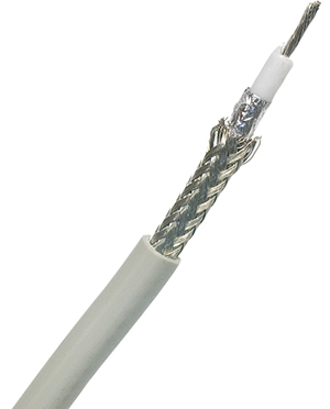
FIGURE 3.1-4 A stripped view of a typical coaxial cable
Fiber
Fiber optic cable uses either a laser light beam or a light-emitting diode (LED) to transmit Ethernet network frames, which makes it immune to electrical problems such as lightning, short circuits, and static. Fiber optic signals also travel 2000 meters (2 km) or more.
The fiber optic cabling used for data networks, among other applications, is either single mode or multimode. Over single-mode cables, lasers pulse single bursts of light over a core glass or plastic fiber. Multimode fiber carries multiple simultaneous LED signals, each traveling through the medium using a different reflection angle on the core. Because the reflection angles cause the light beam to weaken or disperse over long distances, multimode fiber is limited to relatively short transmission distances.
Most fiber optic Ethernet networks use 62.5/125 multimode cable. The numbers in the name of this cable represent the size of the core filament. The first number (62.5) represents the diameter of the raw core filament in microns, and the second number is the diameter, again in microns, of the core filament and its cladding (a reflective coating applied to the core filament to keep the light inside the strand). Fiber optics are half-duplex; data flows only one way, so fiber connections require two cables.
NOTE A micron is one-millionth of a meter.
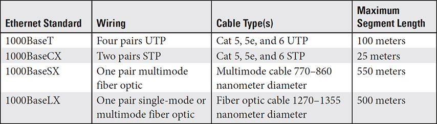
Using fiber optic cabling on a network requires a fiber optic switch and fiber optic network adapter cards. The transfer speed and attenuation distances are limited to that specified by the applicable Ethernet standard. Fiber optic cabling has extremely high transmission rates and distances, but when used for an Ethernet network, the distances can vary with the standard applied. Table 3.1-3 shows a comparison of the Gigabit Ethernet standards for UTP, STP, single-mode fiber, and multimode fiber.
TABLE 3.1-3 A Comparison of Ethernet Cable Medium Standards
Peripheral Cables
A peripheral device is any device connected internally or, more often, externally to a computer. For the most part, a peripheral device is used to enter, display, or transfer data. The connection from a peripheral device to a computer is a communication line between the two. There are three external peripheral device cable and connector types you should know for the A+ Core 1 exam: universal serial bus (USB), serial, and Thunderbolt. The following sections provide information on each of these.
USB
USB connectors are used to interface virtually any device to a PC or mobile device, including keyboards, mouse units, scanners, printers, audio devices, as well as gadgets not typically thought of as peripheral devices, such as lap warmers, cup heaters, personal fans, and more.
The core of USB is the USB host controller, an integrated circuit normally built into the chipset. It acts as the interface between the system and every USB device that connects to it. The USB root hub is the part of the host controller that makes the physical connection to the USB ports. A USB host controller is the boss (the master) of any device (the slave) that plugs into that host controller. The host controller performs two tasks: sending commands and providing power to connected USB devices. The host controller is upstream, controlling devices connected downstream to it. The host controller is shared by every device plugged into it, so speed and power are reduced with each new device.
You can add extra USB ports to a system using either a USB expansion card or a USB hub (see Figure 3.1-5). USB hubs come in powered and bus-powered varieties. Powered USB devices have their own power plug and bus-powered USB devices draw their power from the USB bus. Too many bus-powered devices on a bus-powered hub can cause problems, so it’s best to use powered hubs in such situations.
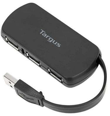
FIGURE 3.1-5 Typical USB hub (image courtesy of Targus Global)

ADDITIONAL RESOURCES For more information about USB, visit www.usb.org.
USB devices are hot-swappable, which means you can connect or disconnect them at any time without powering down your computer. USB technology lets you use hubs to connect up to 127 devices to a single host controller on your computer.
EXAM TIP For the CompTIA A+ 220-1101 exam, you should expect one or more questions on the USB 2.0 and 3.x standards regarding their connectors and their maximum data speeds.
There have been several generations of the USB standard, along with several connector types. Table 3.1-4 provides a quick reference to help you sort them out.
TABLE 3.1-4 USB Standards
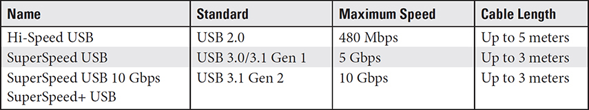
NOTE USB 3.1 doesn’t specify a limit, but interference can make longer cables slower.
Over the past two decades, there have been several types of USB connectors, which have been interchangeable for the most part. For example, Type-A USB plugs would fit USB 1.1 and 2.0 ports. However, the later USB versions, primarily the 3.x and 4 versions, have relatively unique connectors with clearly marked ports. USB 3.x suggests that ports should be blue to differentiate them from earlier versions with black or white ports. USB 3.x plugs are compatible with earlier USB standards, and vice versa. However, either way, new into old or old into new, the result is slower speeds.
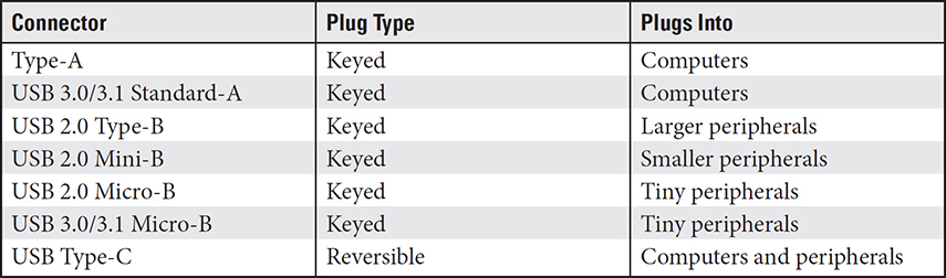
Table 3.1-5 lists the common USB connectors and their purposes. Note that “keyed” means the plug fits into the socket in only one direction. Notice that the type of connector may be used in one or more of the standards.
TABLE 3.1-5 USB Connection Types
Figures 3.1-6 and 3.1-7 illustrate connector types listed in Table 3.1-5.
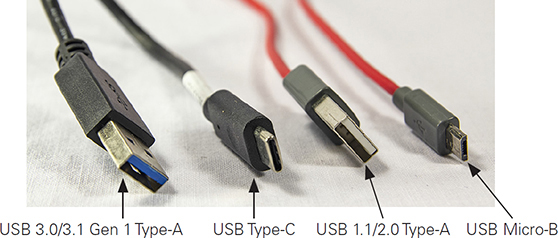
FIGURE 3.1-6 USB Type-A, Type-C, and Micro-B cables
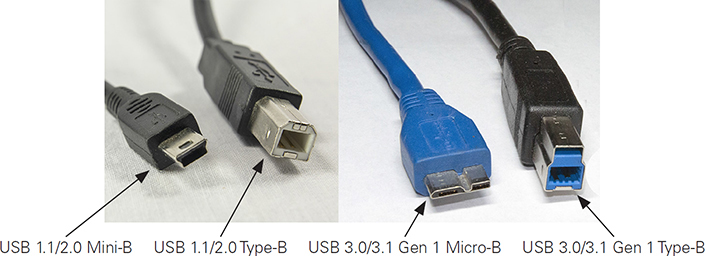
FIGURE 3.1-7 USB 2.0 and USB 3.0 Type-B and Micro-B cables
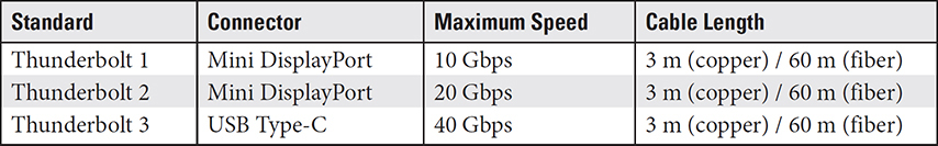
TABLE 3.1-6 Thunderbolt Standards
EXAM TIP CompTIA uses the term USB-C for what others call USB Type-C. CompTIA also uses the term micro-USB for USB Micro-B and mini-USB for USB Mini-B. You might see either forms of the device names on the exam.
The USB Type-C connector is used on Android smartphones and tablets, Apple’s iPad tablets, and many desktop and laptop computers. Newer Apple iPhones use a cable with a Lightning connector on one end and a USB-C on the other, both of which aren’t keyed, so they’re easier to use. USB-C is a form factor, not a specification. USB-C ports might run at USB 3.1 Gen 2, USB 3.1 Gen 1, or USB 2.0 speeds; check the device’s specifications to find out.
EXAM TIP You will likely see micro- and mini-USB, USB Type-C, and Lightning mobile device connection types on the exam. Know their characteristics and differences.
Serial Connector
On today’s computers, most peripherals connect via a USB port, which is a form of a serial connector. However, some legacy desktop systems have one or more specific serial connectors, most likely to be a DB-9 connector. The DB-9 RS-232 connector supports a variety of low-speed peripherals, including dial-up modems, some early mouse units, and early printers. USB ports can be used to connect to serial devices through a USB DB-9 adapter. Figure 3.1-8 shows a DB-9 serial connector and port.
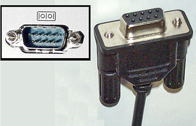
FIGURE 3.1-8 DB-9 serial port and connector
EXAM TIP Expect to see the DB-9 serial connector on the A+ Core 1 exam.
Thunderbolt
The Thunderbolt interface is a high-speed alternative to existing technologies, including USB and FireWire, for connecting peripherals using PCIe and DisplayPort technologies simultaneously, thus combining their capacity. Table 3.1-6 lists the characteristics for each of the versions of the Thunderbolt standard you may see on the exam.
As indicated in Table 3.1-6, the two standards that preceded Thunderbolt 3 were completely different from the USB Type-C connectors it uses. USB Type-C and Thunderbolt 3 are essentially interchangeable. This means that USB Type-C cables are compatible with Thunderbolt ports and that Thunderbolt cabling is compatible with USB Type-C ports. Figure 3.1-9 shows a Thunderbolt 3 port and connector.
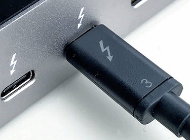
FIGURE 3.1-9 Thunderbolt 3 port and connector
Thunderbolt cables, which tend to be a bit more expensive than USB Type 3 cables, are made with either copper or fiber cores. The copper cables can run up to 3 meters (whether a single cable or chained). Optical runs extend much farther, up to 60 meters. Thunderbolt 3 is much faster than USB Type-C, with transfer speeds of 480 Mbps to 20 Gbps, but transfer rates of 40 Gbps are possible.
Video Cables and Connectors
Video cables connect displays, monitors, HDTVs, and projectors to your computer’s video card or onboard video port. Table 3.1-7 provides an overview of the cables and connector types you should know for the A+ Core 1 exam.
TABLE 3.1-7 Video Cables
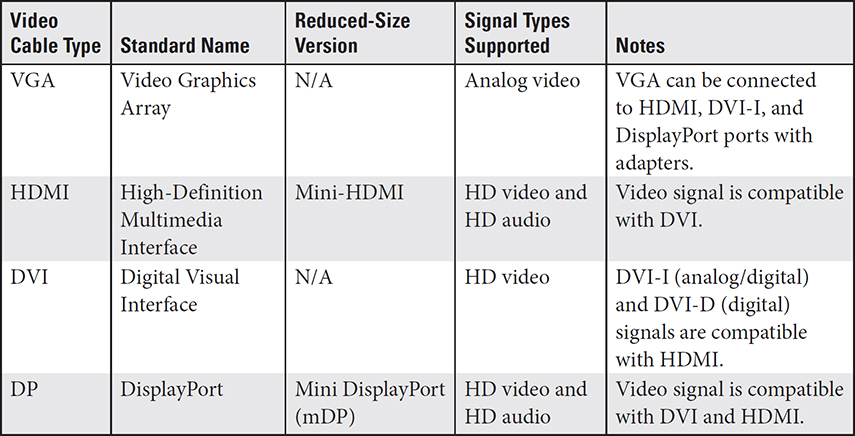
Figure 3.1-10 illustrates some of these video cables, and Figure 3.1-11 illustrates most of these video ports.
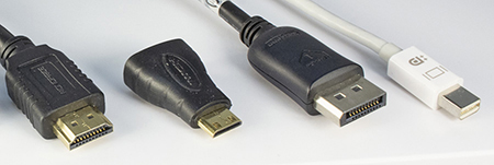
FIGURE 3.1-10 Typical HDMI, Mini-HDMI, DP, and mDP cables/connectors (left to right)
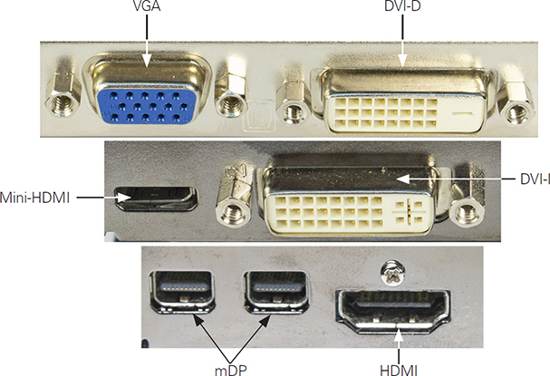
FIGURE 3.1-11 Typical video ports
Hard Drive Cables
Objective 3.1 of the CompTIA A+ 220-1101 exam refers to “hard drive cables,” but it’s important to know that this includes the cable types used with SSDs, optical drives, and tape drives. Different types of cables are used by the different types of hard drive and mass storage devices.
SATA and eSATA
Serial Advanced Technology Attachment (SATA) interfacing is commonly used for hard drives and optical drives. SATA creates a point-to-point connection (see Figure 3.1-12) between a SATA device, such as a hard drive or optical drive, and a SATA controller.
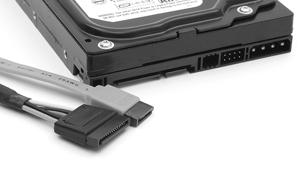
FIGURE 3.1-12 SATA power (wide) and data (narrow) cables and drive connectors
A SATA device’s data stream traverses a thin seven-wire cable that can reach up to a meter in length. The SATA device’s speed depends on the SATA standard in use. The SATA versions—1.0 (1.5 Gbps), 2.0 (3 Gbps), and 3.0 (6 Gbps)—have a maximum throughput of 150 MBps, 300 MBps, and 600 MBps, respectively. Notice that these speeds are in megabytes per second.
External SATA (eSATA) extends the SATA bus to external devices at the same speed as the internal SATA bus. The connector (see Figure 3.1-13) is like internal SATA but is keyed differently; it supports cables up to 2 meters outside the case and is hot-swappable.
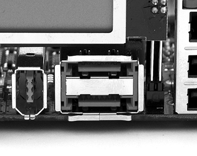
FIGURE 3.1-13 eSATA connectors (in center of photo)
EXAM TIP When you encounter the term hot-swappable on the exam, remember that a hot-swappable drive (or device) is immediately recognized by the system when it is connected, swapped, or replaced while the system is running.
IDE
Integrated Drive Electronics (IDE) is the name used on the CompTIA A+ exam for what is also known as ATA and Parallel ATA (PATA) drives. These drives use a 40-wire flat ribbon cable to connect one or two drives to a host adapter built into a motherboard or an add-on card. IDE interfaces are found on legacy systems, although a few more-recent computers that use SATA for hard drives also use IDE for optical drives. Figure 3.1-14 shows an 80-wire IDE cable and an older, slower 40-wire IDE cable.
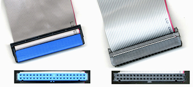
FIGURE 3.1-14 80-wire (left) and 40-wire (right) IDE cables
EXAM TIP Although CompTIA uses the term IDE on the exam, the interface is more often referred to as PATA or ATA/IDE by the industry. They’re the same thing, so be prepared!
SCSI
Small Computer System Interface (SCSI) refers to a large family of internal and external drive and device connectors. Internal SCSI devices such as tape drives and hard drives are used only by servers and connect via 50-wire or 68-wire flat cables that resemble wider versions of IDE cables. External SCSI devices use bulky round cables ranging from 25 pins to 68 pins. Each SCSI device is assigned an ID number, enabling multiple devices to be connected to a single host adapter using daisy-chaining. Unless you work with servers, it’s unlikely you will encounter a SCSI host adapter or device in the field.
The SCSI interface has been largely replaced by Serial Attached SCSI (SAS) for servers and storage arrays. SAS 4, the latest version, runs at up to 22.5 Gbps. SAS also supports SATA drives. Another version of SCSI, Internet SCSI (iSCSI), supports block-level I/O on storage devices through SCSI commands transmitted across a network.
Connectors
As you well know, storage and other types of peripheral devices must be attached to a computer using one form of a connector or another. Many device types use standard connectors, whereas others require a customized or proprietary connector. Connectors have names or designations, but most are referred to by an industry or application registration or a descriptive coding, such as RJ-45 or Mini SAS 4x.
Cable and connector standards are issued by a variety of national and international organizations. The most common of these organizations—and the one’s you’re likely to encounter on the exam—are the Institute of Electrical and Electronics Engineers (IEEE), USB Implementers Frontier (USB IF), Electronic Industry Association (EIA), Telecommunication Industry Association (TIA), Registered Jack (RJ), and International Electrotechnical Commission (IEC).
Connectors also have a gender that indicates which side of a connection a device constitutes. A “male” connector is the side with pins, blades, or spades. A “female” connector has the receptacle slots or pin holes that receive the connecting elements of the male side.
Let’s look at the connectors you are likely to encounter on the A+ Core 1 exam.
Registered Jack Connectors
An RJ connector is a standard managed by the TIA for telecommunication network interfaces for data and voice services. The types of RJ connectors you will likely encounter on the exam are the RJ-11 and the RJ-45 and their configuration.
RJ-11
Dial-up and DSL modem ports look identical to traditional wired telephone jacks and use two-wire RJ-11 telephone cables and connectors (see Figure 3.1-15). The locking clips on the male RJ-11 connectors secure the cable into the port. Most modems also have an output port for a telephone.
FIGURE 3.1-15 RJ-11 connectors on a modem
RJ-45
Network interfaces come in several varieties. Most network interface cards (NICs) and motherboards have an eight-wire RJ-45 port (see Figure 3.1-16). RJ-45 connectors look like wide RJ-11 telephone connectors and plug into the female RJ-45 ports in the same manner that RJ-11 telephone cables plug into a modem.
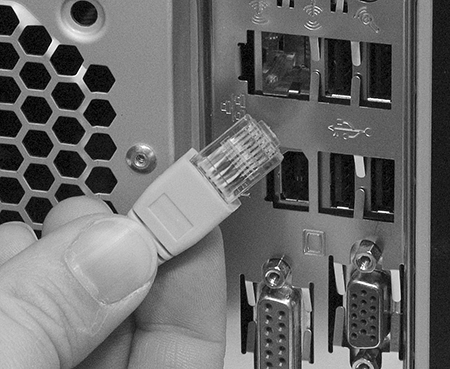
FIGURE 3.1-16 An RJ-45 connecter and port
T568A/B
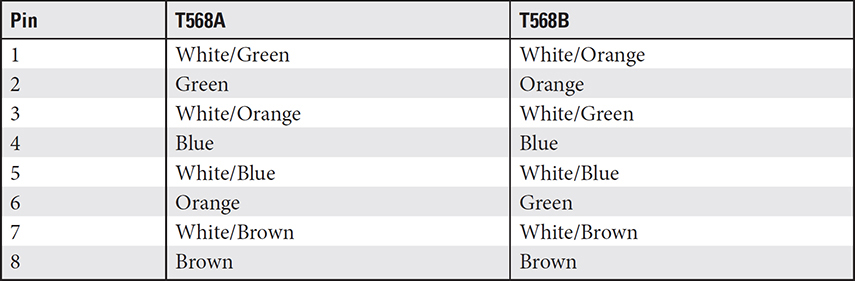
The EIA/TIA T568A and T568B standards, while not specifically connectors, do specify the configuration of TP wiring and RJ-45 connectors. So, if you make up your own connectors, use either the T568A (commercial) or the T568B (residential) standard for their configuration. The wires in TP cable are color-coded (see Figure 3.1-17) and designated with a placement number, as listed in Table 3.1-8.
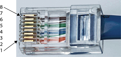
FIGURE 3.1-17 RJ-45 pin numbers using the T568A/T568B standards
TABLE 3.1-8 UTP Cabling Color Chart
EXAM TIP It’s a good idea to know the pin numbers of RJ-45 and their use in straight-through and crossover connectors.
Coaxial Cable Connector: F-Type
Coaxial cable connectors are based on the grade and purpose of the cable. The F-type connector is typically associated with terrestrial “over the air” and cable TV. It’s also the most commonly used connector for coaxial cabling on Ethernet networks. F-type connectors are used to connect cable-based Internet services from a point of presence (POP) in a home or business to the consumer premises equipment (CPE), such as a router or modem. Figure 3.1-18 shows an example of a male F-type connector.
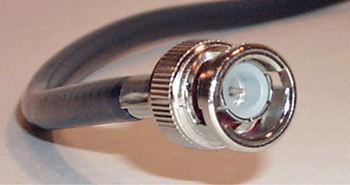
FIGURE 3.1-18 A male F-type connector
EXAM TIP For the A+ Core 1 exam, you should know the F-type coaxial cable connector.
Fiber Optic Cable Connectors
The A+ Core 1 objectives include three specific fiber optic cable connectors you could see on the exam: the straight tip (ST), the subscriber connector (SC), and the Lucent connector (LC), as shown in Figure 3.1-19. Some other fiber optic cable connectors you might see on the exam as wrong answers or distractors are FDDI, MT-RJ, and FC.
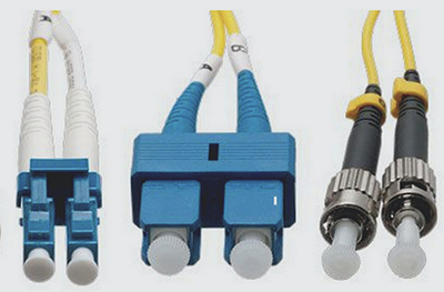
FIGURE 3.1-19 ST (left), SC (center), and LC (right) fiber connectors
Straight Tip
The straight tip (ST) fiber optic connector is a very commonly used connector for multimode networks, such as an industrial or academic campus and large buildings. The ST connector has a “push in and twist” locking mechanism that is also keyed. As shown in Figure 3.1-19, an ST connector uses a long cylindrical polymer or ceramic ferrule to hold the fiber cable.
Subscriber Connector
The subscriber connector (SC) is one of the most used fiber optic cable connectors, due to the facts that it’s simple to install and inexpensive. An SC uses a push-pull function and a locking tab to secure the connection.
Lucent Connector
Like the subscriber connector, the Lucent connector uses a push-pull function, but the locking mechanism is a built-in latch. The LC is used when the space for the connection is limited. An LC is smaller (half the size of an SC or ST connector) and easier to install, which is why LCs are popular with single-mode fiber-in-the-home (FITH) services.
Punchdown Block
On the A+ Core 1 exam, this device is referred to as a punchdown block. However, it’s also commonly called a punch block, a quick connect block, a patch panel, or a terminating block, among a few other terms. A punchdown block, so called because of the action used to install wiring and cabling into it, has a set of insulation displacement connectors (IDCs) into which cable wiring is inserted using a “punchdown” tool and action.
A punchdown block is commonly used as an interconnection device for incoming communication cables and wiring and the internal network as well as for centralizing and consolidating internal network wiring. Punchdown blocks are most commonly installed in a main communications facility that serves an entire building or a communication closet for an area of one or more floors of a building. Among the benefits of installing a punchdown block is that reconfiguring a network may only require moving RJ-45 connections from one port to another.
Two types of punchdown blocks are common in communication facilities: a 66 block and a 110 block. A 66 block is primarily used for voice system wiring. A 110 block, as used in a computer network, has IDCs on one side and RJ connections on the other (see Figure 3.1-20).
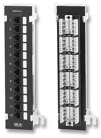
FIGURE 3.1-20 The RJ-45 (left) and punchdown (right) connections of a punchdown block
Molex and Berg
A Molex connector, which gets its name from its original developer, the Molex Connector Company, is a common two-part connection device used to provide DC power to internal components of a PC. Molex is the standard power connector for IDE (ATA, PATA) drives using the 4-pin Molex power connector, shown in Figure 3.1-21. Molex connectors can also be used with other internal DC-powered devices, such as case fans. Figure 3.1-21 shows a Molex power connector.
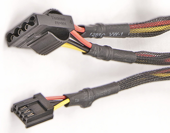
FIGURE 3.1-21 Molex (upper) and Berg (lower) power connectors
Another power connector commonly used to supply power to motherboards is the Berg connector. Named after its developer, Berg Electronics Company, it is more commonly referred to as a P7 or a mini-Molex connector. Figure 3.1-21 includes an example of a Berg connector.
Lightning Port
“Lightning” technology includes a bus and connector developed by Apple to connect its devices, including iPhones, iPads, and so on to computers, monitors, chargers, and more. The male lightning jack is symmetrical, which means that it’s reversible and can be connected to a lightning port regardless of its orientation—unlike USB and other keyed connectors. While the primary use of a lightning cable, which typically has a lightning connector on one end and another standard connector (commonly a USB-A connector) on the other (see Figure 3.1-22), is to charge Apple devices. It can also be used to transfer digital files, such as photos and audio, between iOS devices and a computer.
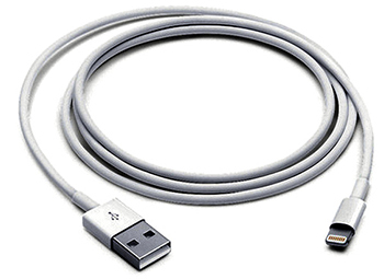
FIGURE 3.1-22 A lightning cable with a USB jack
Adapters
Adapters and converters enable you to connect devices in interesting ways. You can use a cable with DVI on one end and HDMI on the other end, for example, to plug into a DVI port on the video card and the HDMI socket on the monitor. These devices fall into two broad categories based on the problems they solve: connecting one type of video cable or port to another and connecting almost anything to USB.
DVI to HDMI, DVI to VGA
Adapters and converters for video take two primary forms: relatively small devices that fit at one end of a cable, converting it to the desired interface, and cables with built-in converters that have different connectors on each end. The former is more flexible, but the latter is easier to use. Figure 3.1-23 illustrates a DVI-to-HDMI cable, and Figure 3.1-24 illustrates a DVI-to-VGA adapter.
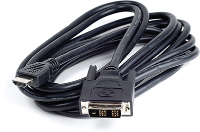
FIGURE 3.1-23 A DVI-to-HDMI cable
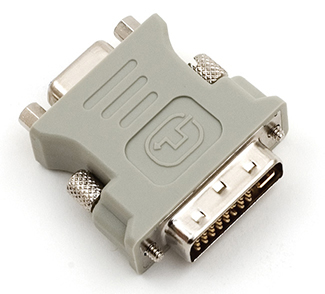
FIGURE 3.1-24 A DVI-to-VGA adapter enables a DVI-I connection to work with VGA displays.
USB to Ethernet
There are many USB adapters for different types of devices, but the most common one is the USB-to-Ethernet (RJ-45) adapter, as it enables computers without Ethernet ports to connect to a twisted-pair Ethernet network (see Figure 3.1-25).
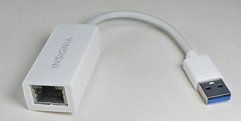
FIGURE 3.1-25 A USB-to-Ethernet adapter enables a USB port to connect to an Ethernet network.
EXAM TIP Other USB adapters you may encounter on the exam are USB-A to USB-B, USB to Bluetooth, and USB to Wi-Fi.
REVIEW
Objective 3.1: Explain basic cable types and their connectors, features, and purposes
• The most common types of network cable for Ethernet networks are Cat 5, 5e, 6, and 6a.
• Ethernet cabling uses RJ-45 connectors.
• Plenum-grade cables are designed for use in plenum (air spaces) and are fire-resistant.
• UTP cables are used in the vast majority of 10/100/1000BaseT networks.
• STP cables are shielded for use in areas of EMI and typically are used only in such environments.
• The T568A and T568B cable standards for UTP cable differ in their pattern and organization of white/green, green, orange, and white/orange wires.
• Coaxial cable is used for cable TV, LANs, and Internet.
• Fiber optic cabling can be used for Ethernet network, SAN, FTTN and FTTH.
3.1 QUESTIONS
1. Company A wants to eliminate separate speakers on desktops and use speakers built into monitors. Which of the following video card standards should be specified?
A. DVI-I
B. DVI-D
C. VGA
D. HDMI
2. Company B is planning to upgrade its Fast Ethernet network to Gigabit Ethernet. In checking existing cables, the network techs have discovered that some areas were wired with Cat 5, some with Cat 5e, and some with Cat 6. Which of the following should they do as part of the upgrade process?
A. Replace all cables with Cat 6.
B. Keep the same cables.
C. Replace Cat 5 with Cat 5e or Cat 6.
D. Replace all cables with Cat 5e.
3. Company C has purchased some new computers that have USB 3.0 ports as well as a USB-C port. It wants to use the USB-C port for very fast external SSD drives. What needs to be determined first?
A. Are USB-C SSD drives available?
B. How fast is the USB-C port?
C. Can the USB-C port work with other form factors?
D. Is USB-C always running at 10 Gbps?
4. Company D wants to run coaxial cable in its offices for use with HDTV. Which of the following cable types should the company specify?
A. RG-6
B. STP Cat 5e
C. STP Cat 6
D. RG-59
5. Company E wants to purchase SuperSpeed USB drives and card readers. However, all its techs can find are devices labeled with a USB version number. Which of the following USB versions does the company need?
A. USB 3.1 Gen 2
B. USB 3.0
C. USB 1.1
D. USB 2.0
3.1 ANSWERS
1. D HDMI carries HD audio and HD video signals.
2. C Cat 5e and Cat 6 support Gigabit Ethernet and either could replace Cat 5.
3. B USB-C supports USB 2.0, USB 3.0/USB 3.1 Gen 1, and USB 3.1 Gen 2 speeds.
4. A RG-6 is the standard for HD video.
5. B USB 3.0 (aka USB 3.1 Gen 1) is the version number for SuperSpeed USB.
 Given a scenario, install the appropriate RAM
Many computer users mistakenly believe that programs run directly off the hard drive. This is rarely the case, because even the fastest hard drive can’t keep up with the slowest CPU. Instead, programs must be transferred to a super-fast medium that can supply a CPU with the instructions and data it needs to run an application at the required speed. The medium capable of providing this support to the CPU is random access memory, or RAM. Launching an application loads the necessary files from the hard drive into RAM, where the CPU can access the data to run the program.
NOTE Technically, you can use a hard drive or flash drive as virtual memory to expand the available RAM, but these devices are not nearly as fast as RAM, and it isn’t quite the same as running a program from where it is stored on a hard drive.
RAM was once a precious commodity, and even a small upgrade cost hundreds of dollars. These days, it’s not very expensive to add more RAM, and it is often the best upgrade for a sluggish system. This doesn’t mean you can just grab any type of RAM; you’ve got to match the motherboard with the right type of RAM, running at the right speed. Manufacturers have produced RAM in many physical form factors (sometimes called packages) and technologies over the years. This section looks at the types of RAM included in Objective 3.2 of the CompTIA A+ Core 1 (220-1101) exam.
RAM Packages
For the A+ Core 1 exam, it’s important you understand the form, fit, and function of the different types, configurations, and packaging of the various RAM technologies. Remember that the A+ exams are testing to see if you can apply your knowledge to a particular situation or scenario. The types of RAM you should know for the exam are discussed in the following subsections.
Dual Inline Memory Modules
The memory modules found in virtually all desktop computers use an inline memory module form. Until 2000, single inline memory module, or SIMM, was the standard. This technology evolved to dual inline memory module, or DIMM. A DIMM is a circuit board on which dynamic RAM integrated circuits are mounted in series. The DIMM form factor is the dominate module for adding memory to personal computers, printers, or servers. There are standard and proprietary DIMMs, but the two most used are the 133.35-mm (millimeter) module used in desktop computers and other larger devices and the 67.6-mm small outline module, or SO-DIMM, used in laptop computers. Figure 3.2-1 shows examples of these two DIMMs.
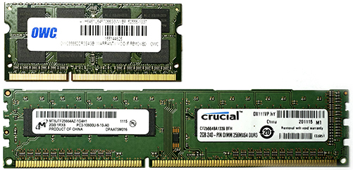
FIGURE 3.2-1 A DIMM (bottom) and a SO-DIMM (top)
Memory Architectures
Several memory architectures are used in computers. Dynamic RAM (DRAM) is the most-used basic memory architecture. Figure 3.2-2 illustrates how DRAM is the foundation for most other memory types.
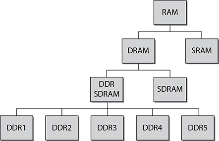
FIGURE 3.2-2 DRAM is the root of most RAM architectures.
The following are the memory architectures you can expect to find on the A+ Core 1 exam:
• Dynamic RAM (DRAM) DRAM must be refreshed (recharged) every few milliseconds to retain its content. It is dynamic because the value it holds can be refreshed with a different value, as needed.
• Synchronous DRAM (SDRAM) Most DRAM is asynchronous, meaning that it’s not synchronized to the system clock. SDRAM is synchronized to the system clock, which means that it operates at higher transfer rates than basic DRAM. You may not see it specifically on the exam, but SDRAM is the type of DRAM memory that is the foundation architecture for the Double Data Rate (DDR) memory types.
Double Data Rate Memory
Basically, double data rate (DDR) memory’s name comes from the fact that it transfers data in and out at twice the rate of single data rate (SDR) memory, specifically SDRAM. The “double” in DDR indicates that 2 bits are transferred in a single clock cycle from memory to an I/O register, an action called a “2-bit prefetch.”
DDR memory has evolved from its original introduction in 2000 through five versions to today’s DDR5. Each of the versions has added size, speed, and bandwidth to the prefetch function. The following briefly describes DDR3 through DDR5 (DDR1 and DDR2 are not referenced on the exam):
NOTE Prefetching decreases transfer times by buffering or caching a resource (such as a set of bits) before it is required.
• DDR3 DDR3 boasts higher speeds, more efficient architecture, and around 30 percent lower power consumption than DDR2. Desktop DDR3 uses a 240-pin DIMM. DDR3 doubles the size of the prefetch buffers from 4 bits to 8 bits, giving its bandwidth a huge boost when reading contiguous data. Many DDR3 systems support dual- and triple-channel memory configurations. Typical sizes of DDR3 DIMM sticks range from 1 GB up to 8 GB.
• DDR4 DDR4 provides higher speeds, more efficient architecture, and around 20 percent lower power consumption than DDR3. Desktop DDR4 uses a 288-pin DIMM that has a slight curve on both ends of its motherboard connector. Typical sizes of DDR4 DIMM sticks range from 4 GB up to 64 GB.
• DDR5 Introduced in 2021, DDR5 further improves channel efficiency, power management, and performance and is compatible with the multi-core architectures of emerging computer systems. DDR5 provides almost twice the bandwidth of DDR4 and nearly 50 percent more speed. Typical sizes of DDR5 DIMM sticks range from 8 GB up to 128 GB.
Table 3.2-1 and Figure 3.2-3 provide features and a visual comparison of DDR3, DDR4, and DDR5 DIMMs.
TABLE 3.2-1 Comparison of DDR Memory Versions
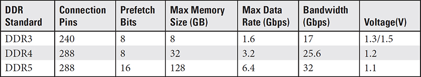
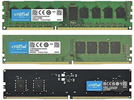
FIGURE 3.2-3 DDR3 (top), DDR4 (center), and DDR5 (bottom) DIMMs compared (images courtesy of Micron Technologies, Inc.)
NOTE Both DDR4 and DDR5 have 288 pins on their edge connectors, but each uses a different pin arrangement.
EXAM TIP You should be familiar with the various RAM sizes and speeds for DDR3, DDR4, and DDR5.
ADDITIONAL RESOURCES To familiarize yourself with the many RAM standards and specifications for both desktops and laptops, visit www.crucial.com, paying attention to the characteristics, such as module size, package, and features.
Handling and Installing DIMM
Proper RAM handling and installation procedures prevent damage to your system. This section reviews the proper way to handle desktop RAM and how to install it.
RAM is extremely sensitive to electrostatic discharge (ESD). Therefore, you need to take precautions while transporting, handling, and installing it. Always store RAM in antistatic bags or sleeves when it’s not installed on a computer, and keep it labeled with the type, size, and speed so that you can identify it later. Wear an antistatic wrist strap and ground yourself before working with RAM. Don’t take a RAM stick out of its bag before you are ready to install it. Also, be sure to handle RAM by the edges of the module and avoid touching its contacts or circuits.
To install DIMMs, first power down the computer and unplug it from the AC outlet. DIMM sticks fit into their sockets vertically. Each of the memory slots/sockets on the motherboard will have a guide bar with which the guide notch on the DIMM is matched to ensure the DIMM is properly installed, as illustrated in Figure 3.2-4, and to prevent it from being inserted the wrong way. Make sure that the RAM retention clips at either end of the socket are pushed completely outward.
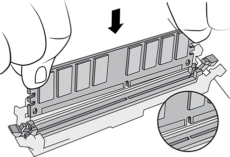
FIGURE 3.2-4 Match the guide slot on the DIMM with the guide bar in the memory socket.
Hold the RAM stick by the edges, position it above the RAM socket, and press it straight down into the slot with gentle pressure (see Figure 3.2-5). When the RAM is fully inserted, the retention clips will rotate into the retention notches on each end of the stick. Snap the clips firmly into place, and you’re done.
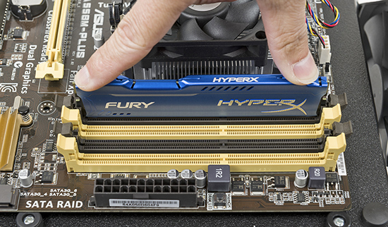
FIGURE 3.2-5 Properly seating a DIMM
Barring ESD, not a lot can go wrong. The main thing to look for is improper seating. If the retention clip doesn’t engage fully, your RAM stick isn’t inserted completely. DDR3 sockets typically use a retention clip on both ends. DDR4 sockets use a retention clip on one end and a fixed guide rail on the other end, and DDR5 sticks will only fit into DDR5 slots on a DDR5 motherboard. If, for any reason, the DDR stick doesn’t easily fit, it’s not in the right position or it’s the wrong memory.
To remove a DIMM, push the retention clip(s) on the socket outward. These clips act as levers to eject the stick partially so that you can then pull it all the way out.
Laptop RAM
Laptops, notebooks, some all-in-one computers, and other small form factor PCs all use DDR RAM, just as desktops do. However, due to the space limitations of these devices, RAM, including DDR RAM, is packaged as small outline dual inline memory modules (SO-DIMMs, shown in Figure 3.2-6). Although it should be obvious, you should know that DIMMs and SO-DIMMs are not interchangeable.
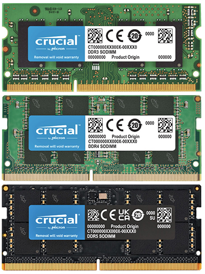
FIGURE 3.2-6 DDR3 (top), DDR4 (center), and DDR5 (bottom) SO-DIMMs compared (images courtesy of Micron Technologies, Inc.)
The performance characteristics of a SO-DIMM are essentially the same as a similar DIMM with the same technology. The information in Table 3.2-1 applies to both DIMMs and SO-DIMMs. A SO-DIMM is installed in the same way a DIMM stick is installed in a larger unit. The key thing in either case is to use the alignment notch on the card to position the module into the mounting slot.
There are SO-DIMMs for each of the DDR versions, including DDR5. There are also low-voltage versions of the DDR3 SO-DIMMs, identified as DDR3L modules. The low-voltage versions and the standard voltage versions aren’t necessarily compatible, so be sure you know with which type you’re working. A DDR5 SO-DIMM requires 1.1 V (volts), which is 0.1 V lower than that of the DDR4.
• DDR3 SO-DIMM DDR3 SO-DIMM is packaged in a 204-pin module, such as the one shown in Figure 3.2-6. Note that some DDR3 SO-DIMMs use low-voltage DDR3 memory. These modules are called DDR3L SO-DIMM. Check the specifications for a specific device to determine if it uses standard voltage (DDR3) or low-voltage (DDR3L) memory.
• DDR4 SO-DIMM DDR4 SO-DIMM is packaged in a 260-pin module, such as that shown in Figure 3.2-6. A DDR4 SO-DIMM is slightly wider than previous SO-DIMM types.
• DDR5 SO-DIMM This module is a 262-pin SO-DIMM with two independent I/O channels for increased bandwidth, the efficiency of fly-by topology, and a standardized sideband bus. Figure 3.2-6 shows an image of a DDR5 SO-DIMM.
EXAM TIP You should be able to differentiate the DIMM and SO-DIMM form factors and the number of pins in the edge connectors of each for the A+ Core 1 exam.
Handling and Installing SO-DIMM Sticks
Just like with a desktop, protect yourself and the portable device by removing all power and protect the SO-DIMMs by using proper ESD avoidance techniques. With portables, removing power includes disconnecting removable batteries. If it has built-in batteries, consult the manufacturer’s resources to check if and how you can safely work on it.
NOTE Some portables have both built-in and removable batteries.
Once you know you can work safely, confirm what kind of RAM you need by checking the manufacturer’s website or manual. Next, check the existing RAM configuration to confirm what you need to buy. To go from 4 GB to 8 GB, you need to know if the portable has one 4-GB module or two 2-GB modules.
Next, locate the RAM slots. They’re often behind a panel on the bottom of the portable, as shown in Figure 3.2-7, but sometimes they’re separated.
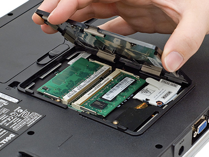
FIGURE 3.2-7 Removing a RAM panel
Then you press out on the retaining clips, and the RAM stick pops up (see Figure 3.2-8). Gently remove the old stick of RAM and insert the new one by reversing the steps.
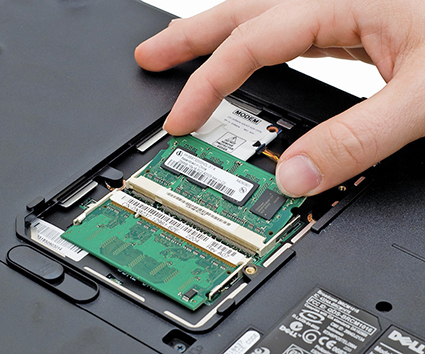
FIGURE 3.2-8 Releasing the RAM
Confirming RAM Installation
Once you’ve installed RAM, confirm that the computer recognizes it by booting up and checking the RAM count message or by looking in the UEFI/BIOS setup utility (see Figure 3.2-9). Modern systems automatically detect the RAM size and configure the system accordingly. You rarely need to reconfigure these RAM settings. You can also verify the amount of installed RAM from within the operating system—for example, in any version of Windows, simultaneously press the WINDOWS and PAUSE keys to bring up the System Properties applet.
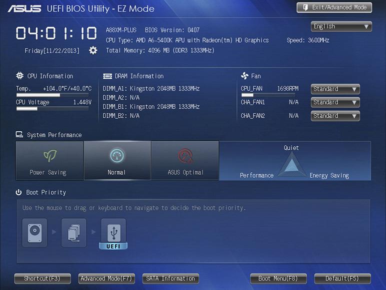
FIGURE 3.2-9 Confirming RAM installation by checking total memory in UEFI BIOS Utility
Performance Configurations for Desktop and Laptop
Current desktop and laptop motherboards use multichannel memory configurations to increase memory performance. With a 64-bit data bus, DIMMs deliver 64 bits of data at a time on a single memory channel. A dual-channel memory architecture doubles the number of data bits from 64 to 128, which also doubles the available bandwidth. Since memory modules are 64-bit devices, two memory modules are required to be installed in parallel to achieve a dual-channel architecture. A triple-channel memory architecture requires three memory modules be installed in series (on memory slots of the same color) to create a 192-bit data bus. To achieve a quad-channel memory architecture—you guessed it—four memory modules are installed to create a 256-bit memory data bus. Use identical RAM sticks to populate a bank for multichannel memory modes. Always check the motherboard or system documentation for details.
Each of the multiple-channel memory architectures requires a memory controller that supports its number of channels. Dual-channel memory controllers support two channels simultaneously, and triple-channel and quad-channel configurations require memory controllers that support three and four channels, respectively. Motherboards that support a multichannel mode can also run in lesser-channel modes, but the best performance is provided by the highest mode the motherboard supports.
EXAM TIP Know the differences and configurations of single-, dual-, triple-, and quad-channel memory.
Error-Correcting Memory
High-end, mission-critical systems often use special error-correction code (ECC) RAM that uses special circuitry to detect and correct errors in data. ECC RAM contains circuitry that not only detects errors but corrects them on the fly without interrupting system processes. ECC RAM is common on performance-enhanced workstations and servers.
Virtual Memory
It may seem like everything is or could be virtual on a computer these days. One virtual component is available on “virtually” any system with an OS, which of course is all of them. Virtual memory or virtual RAM is only virtual in the sense that it’s not actually a physical part of a system’s main memory (RAM). Instead, it’s a partition of secondary storage, usually a hard disk, set aside as logical memory.
Virtual memory is controlled by a memory management unit (MMU) of the operating system. The virtual memory area is commonly referred to as swap space or a swap file because it’s used to temporarily store idle or low-priority pages of memory content and free up memory space for an active process.
The amount of virtual memory to configure on a system varies with the operating system, the applications running on the machine, and a few other factors. You can have too much virtual memory, in which case the MMU is constantly thrashing, or moving pages in and out of memory and to and from virtual memory. Common errors associated with virtual memory issues can be out of memory and thrashing, both of which can be caused by the amount of memory allocated to the swap space.
REVIEW
Objective 3.2: Given a scenario, install the appropriate RAM
• Desktop RAM uses the DIMM form factor, which is available in DDR3, DDR4, and DDR5 forms.
• DIMMs are installed by lining up the module with the appropriate RAM slot and pressing the DIMM down until it locks into place.
• Laptop, notebooks, and other small form factor computers use the SO-DIMM form factor for RAM. It is available in the same forms as DIMMs.
• SO-DIMMs are installed by lining up the module with the appropriate RAM slot at an angle, pushing the module into the slot, and pivoting the top of the module until it locks into place.
• Single-channel memory accesses a single DIMM as a channel.
• Dual-channel memory accesses two DIMMs as a channel for greater bandwidth.
• Triple-channel memory accesses three DIMMs as a channel for even greater bandwidth.
• Quad-channel memory accesses four DIMMs as a channel for still greater bandwidth.
• DIMM slots on multichannel systems for a given bank are typically the same color. Use identical RAM sticks to populate a bank for multichannel memory modes.
• Error-correction code (ECC) RAM contains circuitry that not only detects errors but corrects them on the fly without interrupting system processes.
• Virtual memory is an area on secondary storage used to provide additional backup space to the MMU.
3.2 QUESTIONS
1. How many pins does a module of DDR4 DIMM RAM use?
A. 108 pins
B. 186 pins
C. 205 pins
D. 288 pins
2. What is stored in RAM?
A. Currently running programs
B. Programs that aren’t running
C. Nothing
D. Hardware information
3. How many DIMM cards are required to achieve a 256-pin architecture?
A. One
B. Two
C. Three
D. Four
4. You are adding RAM to a dual-channel system that has one 4-GB module to upgrade it to 8 GB. Which of the following do you need to confirm before you buy more RAM?
A. The current stick’s brand of RAM
B. The current stick’s speed of RAM
C. The current stick’s type of RAM
D. All of the above
5. You are purchasing 288-pin RAM to upgrade computers in your organization. What type of RAM are you purchasing?
A. DDR5 SO-DIMM
B. DDR4 SO-DIMM
C. DDR4 DIMM
D. DDR5 DIMM
3.2 ANSWERS
1. D DDR4 DIMM memory uses a 288-pin connector.
2. A RAM is the workspace used by programs as they are running. Programs that are not running are located on a local or network storage device.
3. D Quad-channel memory with four DIMMs creates a 256-bit memory architecture.
4. D To run the computer in dual-channel mode for better speed, the new module must be identical to the old, so all of these factors must be matched.
5. D Standard DDR5 DIMMs have 288 pins. A DDR5 SO-DIMM has only 262 pins.
 Given a scenario, select and install storage devices
The large-volume data storage industry is in a definite period of massive transformation, with flash memory and storage media technologies rapidly replacing magnetic and optical media. Nevertheless, you should expect to encounter magnetic, solid-state, optical, and flash media in your work as a tech, and all four types are important parts of this objective.
Hard Drives
Traditional hard disk drives (HDDs) store data magnetically on spinning platters, using fast-moving actuator arms with read/write heads that are controlled by a servo motor (see Figure 3.3-1). The important properties are physical size, storage capacity, spindle speed, cache size, and interface.
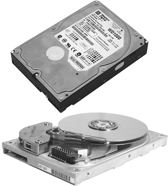
FIGURE 3.3-1 Inside a hard drive
Most modern HDDs are 2.5 or 3.5 inches wide and have storage capacities measured in gigabytes (GB, billions of bytes), terabytes (TB, trillions of bytes), or petabytes (PB, 1024 terabytes). The 2.5-inch HDD is primarily used in laptops and external USB or Thunderbolt storage peripherals. The 3.5-inch HDD is common to desktop and server computers and external AC adapter powered storage peripherals. Currently, 2.5-inch HDDs have a storage capacity of 4 TB, and 3.5-inch drives store up to 20 TB.
EXAM TIP Know the HDD 2.5- and 3.5-inch form factors and spindle speeds as well as the drive categories represented.
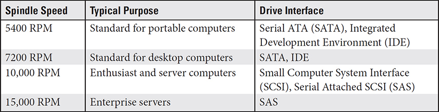
Hard disk drives with higher spindle speeds seek, write, and read faster, but in doing so, they consume more power and generate higher heat and noise. Table 3.3-1 shows common HDD spindle speeds with typical uses. Cache size, measured in megabytes (MB), affects the drive’s sustained throughput.
TABLE 3.3-1 Typical HDD Spindle Speeds
Solid-State Drives
Solid-state drives (SSDs) use flash memory chips to store data. SSDs weigh less, have no moving parts, seek faster, have higher throughput, consume less power, produce less heat, have better shock resistance, and last longer than HDDs. The only downside is that HDDs have the advantage in cost.
Most consumer SSDs use a SATA 2.5-inch hard drive format or an M.2 flash drive format. An M.2 SSD is a small form factor SSD that uses two different internal data bus designs: serial ATA (SATA) and Non-Volatile Memory Express (NVMe). The original form factor for SSDs is SATA 2.5 inch. Figure 3.3-2 compares a SATA 2.5-inch drive with an M.2 drive.
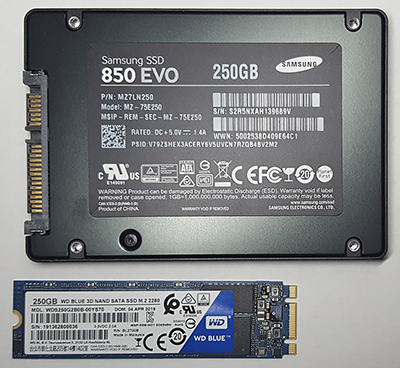
FIGURE 3.3-2 SATA (top) and M.2 (bottom) SSDs
NOTE Confused by all the xxD acronyms yet? Hard drive and hard disk were traditional synonyms, but in this book, we use hard drive as an umbrella term, including HDD and SSD.
NVMe
Non-Volatile Memory Express (NVMe) is a protocol that uses the PCI Express (PCIe) bus to allow computers to connect to SSD devices. NVMe is used by SATA and standard M.2 SSDs. NVMe drives transfer data at 2.5 to 3 times the speeds of SATA and standard M.2 SSDs.
SATA
The serial ATA (SATA) hardware interface is primarily used for connecting HDD storage devices to a computer. SATA is a faster version of the legacy parallel ATA (PATA) interface, both of which are IDE devices, which have the device controllers in the drive. SATA drives include SATA SSD, M.2 SSD, mSATA SSD, and several others.
EXAM TIP The M.2 form factor supports both NVMe and SATA SSDs. You might encounter a question that asks about the differences, so keep in mind that NVMe is faster but doesn’t work in all M.2 slots.
mSATA
The name mSATA refers to mini-SATA, which is a standard developed by the SATA International Organization for an ultra-thin, low-power storage device. The form factor of mSATA is smaller than that of most SATA SSDs. Despite its smaller size, an mSATA device can store up to 1 TB. Figure 3.3-3 shows an example of an mSATA drive.
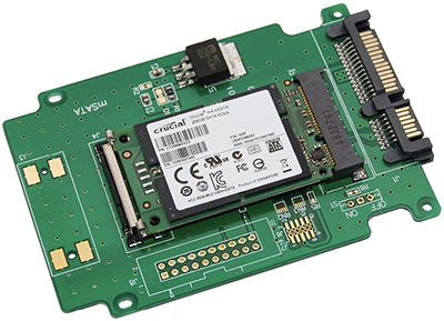
FIGURE 3.3-3 An mSATA drive (image courtesy of Micron Technologies, Inc.)
M.2 SSD
An M.2 SSD is even smaller than an mSATA SSD, which makes it popular for tablet computers and ultra-thin notebooks and the like. An M.2 SSD module has a capacity of up to 2 TB and is inserted into an interface circuit board using mating connections that are either B key sockets or M key sockets. These modules are available as M.2 SATA and M.2 NVMe (see Figure 3.3-4).
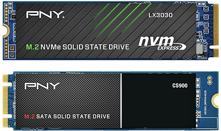
FIGURE 3.3-4 M.2 modules: M.2 NVMe (top) and M.2 SATA (bottom) (image courtesy of Samsung)
Flash Memory
Flash memory, which uses solid-state technology like that found in SSDs, is rapidly displacing other data storage technologies. For the exam, you need to know the two flash memory families: flash drives (aka, thumb drives) and memory cards.
Flash Drives
Flash drives connect to a computer through a standard USB connection. Flash drives and memory cards have very different usages: flash drives have effectively replaced most of the legacy removable storage, such as floppy disks, CD-RW, and the like. Generally, a flash drive is connected to a computing device through either a USB Type-A or Type-C. The capacity of flash drives continues to increase with advances in flash memory, with these drives having storage capacities up to 2 TB.
Memory Cards
Memory card is a generic term for different small insertion cards commonly used in portable devices, such as notebooks, cameras, tablets, and other small and mobile devices. Memory cards vary in type, storage capacities, and form factors. The most common forms used with computing equipment are Secure Digital (SD), microSD, and CFexpress.
SD Card
Although it’s considered to have been replaced by later memory card types, SD cards (examples of which are shown in Figure 3.3-5) remain relevant in computing. Smaller form factor versions, such as miniSD and microSD, share a general format, although the smaller types may require a converter to fit into the larger SD slot. SD cards have storage capacities up to 2 TB.
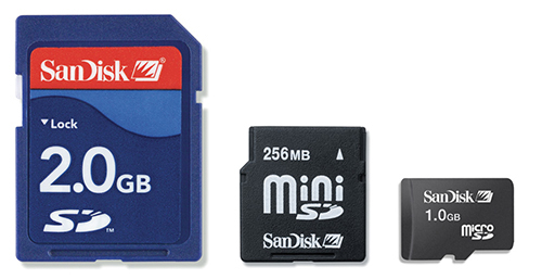
FIGURE 3.3-5 Assortment of SD memory cards
ADDITIONAL RESOURCES To learn more about the different form factors, speeds, and capacities of SD and CF cards, see www.sdcard.organd and https://compactflash.org/.
EXAM TIP Be familiar with the differences between USB flash drives and memory cards, including capacities and uses.
Installing Storage Devices
Three types of interfaces are used for internal storage devices on recent systems: IDE, SATA, and M.2. This section explains how to install devices that use these interfaces.
Installing SATA Drives
There used to be a few catches when installing SATA drives; these days, just connect the power, plug in the controller cable (see Figure 3.3-6), and wait for the OS to automatically detect the drive. The keying on SATA controller and power cables makes it impossible to install incorrectly.
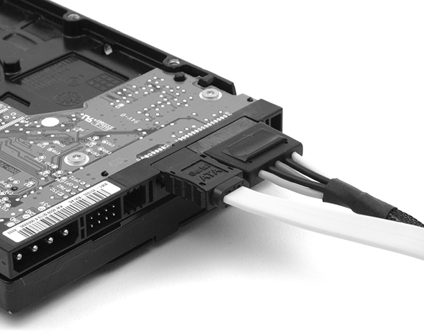
FIGURE 3.3-6 Properly connected SATA cables
Since motherboards come with many SATA connectors, how does the system find the right hard drive to boot up to? That’s where the BIOS/UEFI settings come into play. By default, boot order and drive letter priorities are based on SATA controller IDs: SATA 0 is C:, SATA 1 is D:, and so on.
EXAM TIP BIOS/UEFI setup utilities enable you to change boot order easily, which is great for multi-OS computers.
When installing optical drives, you might also need to install movie playback apps supplied with some drives. The SATA interface works the same way with any type of SATA drive.
Installing IDE Drives
If you need to install an IDE drive, each drive on the cable (which supports up to two drives) must be configured via a jumper block, which is a small plastic electronic connector that ties together two (or more) pins in a configuration block to set a configuration type.
The configuration block on an IDE drive is located next to the Molex power connector on the back of the drive. As illustrated in Figure 3.3-7, the two pins on which the jumper block is placed (an action referred to as jumpering) set the role of the drive. All drives connected to an 80-wire cable are set as CS (cable select). When two IDE drives are connected to a legacy 40-wire cable, one drive is jumpered as MA and the other as SL. The jumpering for a single device on a 40-wire cable varies, so you should see the drive’s documentation for its settings.
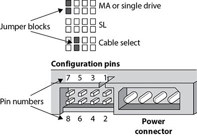
FIGURE 3.3-7 The jumper settings for an IDE device
Installing M.2 Drives
With any type of M.2 device, including standard SSDs, NVMe SSDs, and other types of M.2 devices used in laptops, the selection and installation processes have these steps:
1. Select a device that fits into the slot.
2. Secure the device with a mounting screw.
All M.2 cards are 22 mm wide, with lengths varying from 30 mm to as much as 110 mm. The most common size, however, is 2280 (22 mm wide, 80 mm long), as illustrated in Figure 3.3-8.
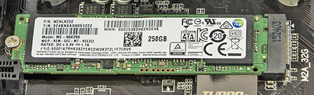
FIGURE 3.3-8 An M.2 2280 SSD installed and secured into an M.2 slot
RAID
A redundant array of independent (or inexpensive) disks (RAID) uses multiple hard drives to increase performance and protect data. Motherboards with built-in RAID controllers may have a BIOS/UEFI setting to enable or disable RAID (see Figure 3.3-9). The following list describes each of the RAID level you should know for the Core 1 exam.
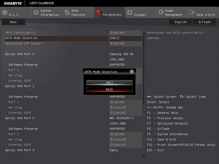
FIGURE 3.3-9 BIOS/UEFI settings for RAID
EXAM TIP A RAID array collects two or more hard drives into a logical unit. CompTIA expects you to know RAID levels 0, 1, 5, and 10.
• RAID 0: Disk striping Disk striping requires at least two drives. It increases performance by splitting work over multiple drives, but it does not provide redundancy to data. If any drive fails, all data is lost.
• RAID 1: Disk mirroring/duplexing RAID 1 arrays require at least two hard drives, although they also work with any even number of drives. RAID 1 mirrors data across multiple drives, providing safety at the cost of storage space (since data is duplicated; you need two 2-TB drives to store 2 TB of data).
• RAID 5: Disk striping with distributed parity RAID 5 distributes data and parity information evenly across all drives. This is the fastest way to provide data redundancy. RAID 5 arrays effectively use one drive’s worth of space for parity, requiring a minimum of three drives. In RAID 5, three 2-TB drives provide a capacity of 4 TB, while four 2-TB drives provide a capacity of 6 GB.
• RAID 10: Nested, striped mirrors RAID 10 takes two mirrored pairs of drives and stripes them together. This creates an array with excellent speed and redundancy, though it takes four drives as a minimum. RAID 10 is not one of the original RAID levels but is fairly common today. RAID 10 combines RAID levels 0 and 1 to create a RAID configuration that mirrors two striped-drive pairs (RAID 0+1) and stripes two mirrored-drive pairs (RAID 1+0 or RAID 10). Arrays that combine single standard RAID types are multiple RAID solutions or nested RAID.
EXAM TIP Be sure you know and understand the RAID 0, 1, 5, and 10 (1+0) configurations for the A+ Core 1 exam, especially the minimum number of disks required for each and the basic method(s) each implements, such as mirroring, striping, redundancy, and so on. You will encounter at least one of these on the test.
Optical Drives
Compact disc (CD), digital versatile disc (DVD), and Blu-ray Disc (BD) drives use lasers to read (and sometimes to write or burn) data on optical discs. These devices have been and still are used to back up and archive data. Internal optical drives use the SATA interface and external optical drives typically connected to USB ports.
All three of these optical media are available in three types: read-only(R), write-once (W), and rewritable (RW). Optical combo drives read and write to the different optical media types. However, you should always check compatibility, especially with older drives.
NOTE Optical discs use a unique Compact Disc File System (CDFS), more accurately called the ISO 9660 file system.
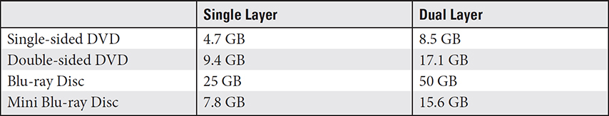
CDs have a capacity of either 650 MB or 700 MB. DVD and Blu-ray media have several combinations of media types and either single or dual layering, which translate to different storage capacities. Table 3.3-2 shows DVD and Blu-ray Disc capacities.
TABLE 3.3-2 Common DVD/Blu-ray Disc Capacities in DVD-Industry Gigabytes
REVIEW
Objective 3.3: Given a scenario, select and install storage devices
• SATA HDD, SSD, and optical drives are installed using a SATA data cable and a SATA power cable.
• M.2 drives are available in conventional (SATA SSD speed) and NVMe (2.5 to 3 times faster) types.
• HDDs are available in 2.5-inch and 3.5-inch form factors.
• HDDs have spindle speeds of 5400 RPM, 7200 RPM, 10,000 RPM, and 15,000 RPM.
• 3.5-inch drives are used in AC-powered enclosures as well as desktops and servers.
• 2.5-inch drives are used in USB-powered enclosures and laptops.
• NVMe uses the PCIe bus to connect to SSD devices.
• mSATA refers to mini-SATA (an ultra-thin, low-power storage device). The form factor of mSATA is smaller than that of most SATA SSDs.
• The most common family of flash memory cards is SD, including miniSD and the very popular microSD.
• RAID 0 is faster than other RAID types because data is striped across two drives; it has no redundancy.
• RAID 1 mirrors the contents of one drive to the other; RAID 5 uses at least three drives and distributes data and recovery (parity) information across all drives; RAID 10 or RAID 1+0 combines striping and mirroring, which requires four drives.
• Optical discs are available in CD, DVD, and BD (Blu-ray) types.
3.3 QUESTIONS
1. Your client is planning to replace 500-GB hard disks with similarly sized SSDs. Assuming compatibility, which of the following would provide the best performance?
A. NVMe 2.5-inch
B. NVMe M.2
C. SATA M.2
D. SATA 2.5-inch
2. Which of the following is not an interface type used for internal storage devices on newer systems?
A. IDE
B. SATA
C. M.2
D. Serial
3. Your client wants to add an NVMe drive to their desktop systems to boost performance, but the M.2 slots in these systems don’t support NVMe drives. Which of the following interfaces can be used instead?
A. SATA
B. PCIe
C. SATA
D. ISO 9660
4. Your client wants to choose a RAID array type that offers excellent speed and reliability. Which of the following is the best match for this requirement?
A. RAID 10
B. RAID 1
C. RAID 5
D. RAID 0
5. Your client accidentally purchased a microSD card for their digital camera instead of an SD card. Which of the following is the best way to use the card?
A. Copy the data from an existing card to the new card.
B. Return the card to the store for the correct type.
C. Use an adapter with the card.
D. Buy a new camera that uses microSD cards.
3.3 ANSWERS
1. B The NVMe M.2 SSD is the fastest type of SSD.
2. D IDE, SATA, and M.2 are internal storage device interfaces. Serial is not used internally in a system.
3. B NVMe drives are available in PCIe cards; NVMe uses the PCIe bus for extra speed over SATA.
4. A RAID 10 combines mirroring for data protection and striping for speed.
5. C SD adapters for microSD cards are very common and often bundled with microSD cards.
 Given a scenario, install and configure motherboards, central processing units (CPUs), and add-on cards
Custom PC configurations and upgrades rely on a tech’s ability to integrate off-the-shelf components from various sources into a working system. In this objective, you learn how to choose, install, and configure compatible motherboards, CPUs, and add-on cards.
Motherboard Form Factor
A form factor defines the motherboard’s size, shape, orientation, how it’s mounted in the computer case, the location of onboard sockets and expansion slots, and more. Essentially, the form factor of a motherboard determines how a computer performs. It sets which components are compatible and can be connected to the motherboard as well as sets operating aspects such as power supply requirements, the size and shape of the case, and to a certain extent what you can do on the computer.
The most common form factors for PC motherboards are ATX and ITX, which stand for Advanced Technology eXtended and Information Technology eXtended, respectively. Each of these form factors has variations, and there are proprietary versions as well. For the most part, form factors are not interchangeable, especially ATX and ITX. These two form factors define separate designs and orientations for not only their motherboards but for all compatible supporting components as well. This means that, for example, ATX motherboards fit into ATX cases, and ITX motherboards fit into ITX cases.
ATX
The ATX motherboard form factor (see Figure 3.4-1) was developed to replace the legacy AT form factor. The ATX form factor rearranged the placement of expansion slots, CPU, and RAM for easier access and enhanced performance. The ATX design also corrected a design problem of the AT motherboards that caused some longer expansion cards to contact the CPU. The ATX standards have changed with advancements in technology, including revisions for new power connectors, power supply fans, and airflow and enhanced cooling.
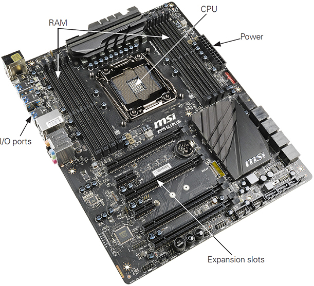
FIGURE 3.4-1 ATX motherboard
The ATX motherboard design collects its onboard I/O ports in a port cluster panel that can be accessed on the back of an ATX case. Figure 3.4-2 illustrates a port cluster on an ATX motherboard and case.
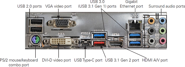
FIGURE 3.4-2 Typical ATX port cluster
The ATX form factor has several variations, including the following two, which are shown on the left side of Figure 3.4-3:
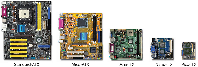
FIGURE 3.4-3 Examples of ATX and ITX form factor motherboards (image courtesy of VIA Labs, Inc.)
• Standard (full-sized) ATX The standard or full-sized ATX (most referred to as the ATX form factor) is 12 inches by 9.6 inches. It supports the latest video and graphic cards, provides seven expansions slots, and fits into a full-size ATX case.
• Micro-ATX Also referred to as mATX, the micro-ATX motherboard is 9.6 inches by 9.6 inches square and uses the same basic motherboard layout and power connectors as the full-sized ATX. The micro-ATX is scaled down to fit into smaller computer cases. While an ATX motherboard won’t fit into a micro-ATX, the smaller form factor can be installed in an ATX case.
EXAM TIP Know the differences between the ATX and the ITX motherboard/ system board form factors.
ITX
The ITX form factor is the most common of the small form factor (SFF) motherboards. Originally, the ITX form factor was for a full-sized motherboard, but it never took hold. However, smaller versions of the form factor have fared much better, specifically the mini-, nano-, and pico-ITX form factors, all shown on the right side of Figure 3.4-3.
Of the three ITX versions, the mini-ITX (or mITX) is the largest at 6.7 inches square. The mini-ITX competes with the larger micro-ATX. The nano-ITX motherboard, at 4.7 inches square, and the pico-ITX motherboard, at 3.8 inches by 2.8 inches, are smaller yet. These much smaller motherboard form factors are used for embedded systems and specialized devices such as routers.
Motherboard Connector Types
A motherboard is more than a large circuit board on which RAM and CPUs are installed. Storage, video, I/O, and other devices are also installed or connected to a motherboard. In the subsections that follow, you learn about the devices that mount on a motherboard or interconnect to each other using the slots, jacks, wires, and support chips that are a part of a motherboard’s design and form factor and collectively known as an expansion bus.
Expansion Bus Architectures
When a device in a computer needs to communicate data or instructions with another device on that computer, it “takes a bus.” In the context of computer technology, a bus is communication line built into or added to a motherboard that allows devices to communicate. A bus is a path created by embedded wiring to which devices are or can be connected. Expansion cards are installed on a motherboard through its expansion bus.
The expansion bus on a motherboard has the primary purpose of providing a standardized access point for adding devices to a computer. The expansion bus allows the motherboard (and through it, the computer) to be customized to the requirements of the user.
Over the years, many expansion bus architectures have been and, in some cases, are still used, including the following:
• Peripheral Component Interconnect (PCI)
• PCI Express (PCIe)
• Small Computer Systems Interface (SCSI)
Although there have been a few others that were specialized to memory cards, video, graphics, and more, the A+ Core 1 exam’s focus is on the PCI and PCIe architectures.
PCI
The Peripheral Component Interconnect (PCI) expansion bus architecture was released to the public domain in the 1990s by the Intel Corporation with hopes of attracting motherboard manufacturers to incorporate it into their designs. Compared to the expansion buses it hoped to replace, PCI was wider at 32 bits, faster at 33 MHz, and more flexible. PCI was also self-configuring, a feature that would lead to the Plug and Play (PnP) standard. The lack a cost for this exceptional technology led manufacturers to incorporate PCI into their products to replace earlier bus structures.
PCIe
PCI Express (PCIe) is an updated version of PCI. However, PCIe uses a point-to-point serial connection instead of PCI’s shared parallel connections to communicate. The serial interface reduces overhead and supports higher transfer speeds without interference from other connected devices. A PCIe device’s point-to-point (direct) connection to the northbridge component of the chipset allows it to transfer data without the need to wait for other devices.
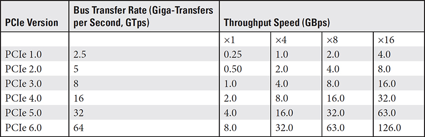
A PCIe lane consists of a single wire on which data is sent and received. However, a PCIe device can use 1, 2, 4, 8, 12, 16, or 32 lanes with corresponding slots referred to as ×1 (by one), ×4 (by four), ×8 (by eight), and so on. Each direction of a lane transfers at a speed that depends on the PCIe version of the expansion card, the PCIe device, and the motherboard. If there is a conflict of PCIe versions between a slot and a card, the slower version is supported.
Some PCIe configurations have special purposes:
• PCIe ×32 Because of its large size and the fact that there really aren’t many devices readily available that use it, this PCIe version is rarely used.
• PCIe ×12 This PCIe version is rarely included on consumer-market PCs but is commonly found on server motherboards.
• PCIe ×2 This PCIe version is used for internal connections but not for expansion slots.
Table 3.4-1 lists the transfer speeds of the various PCIe versions.
TABLE 3.4-1 Data Transfer Speeds of the PCIe Versions
NOTE A lot of laptop computers offer an internal PCIe expansion slot called PCI Express Mini Card, or Mini PCIe. It works like any PCIe expansion slot, although it’s not compatible with full-sized cards.
The most common PCIe slot is the 16-lane (×16) version most video cards use, while ×1 and ×4 are the most common general-purpose PCIe slots. The first PCIe motherboards used a single PCIe ×16 slot and several standard PCI slots. Figure 3.4-4 compares PCIe and PCI slots on a typical late-model motherboard.
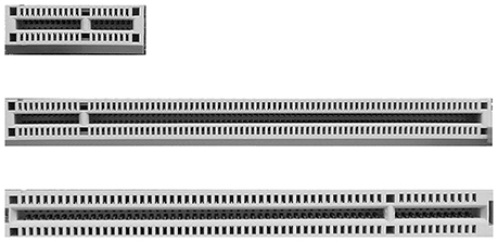
FIGURE 3.4-4 PCIe ×16 (bottom), PCI (middle), and PCIe ×1 (top) slots
EXAM TIP Given a scenario, be able to identify the various PCI and PCIe slots.
SATA
SATA connectors on motherboards might face upward or be positioned along the front edge to face forward. Some motherboards feature ports in both positions (see Figure 3.4-5).
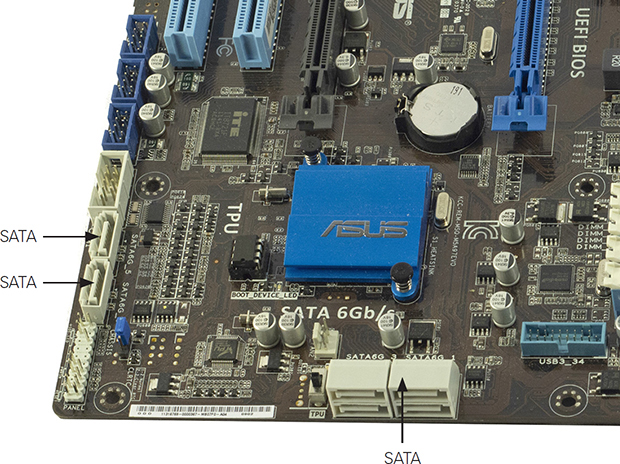
FIGURE 3.4-5 Front-mounted and top-mounted SATA ports on a typical motherboard
eSATA
eSATA is an external (that’s what the e stands for) interface for SATA devices that competes with USB 3.0 for connecting external storage devices. eSATA is essentially a SATA connector accessible from outside a computer for attaching a storage device, which could be a SATA disk drive, an eSATA flash drive, or even a USB 3.0 flash drive. However, eSATA, because it doesn’t supply power, is giving way to the eSATAp (power over eSATA or the eSATA/USB hybrid port) connection standard (see Figure 3.4-6).
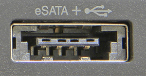
FIGURE 3.4-6 An eSATAp + USB port
Motherboard Headers
A header is a set of pins in a socket on a motherboard that is used to add more connection ports to a computer. The primary two types of headers commonly found on PC motherboards are 1394 (Firewire) and USB, which are not cross-compatible. For example, a USB port panel add-on can be installed in a PC case drive bay and connected to the motherboard using the USB header, like those shown in Figure 3.4-7.
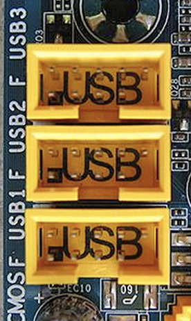
FIGURE 3.4-7 USB headers on a motherboard
A motherboard may also include several other types of headers, including audio, game port, network adapter, and serial and parallel ports.
M.2 Interface
Originally called the Next Generation Form Factor (NGFF), the M.2 interface was developed to overcome the limitations the mSATA to support SFF devices, such as SSD. The M.2 standard supplies better performance and capacity in a smaller package. M.2 supports both SATA and PCIe but can be used in only one at a time. Figure 3.4-8 shows the two sides of an M.2 interface.
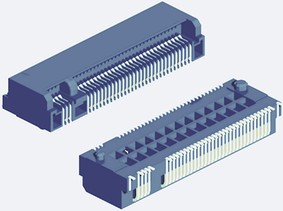
FIGURE 3.4-8 An M.2 interface connector
Motherboard Compatibility
Adding a component such as a CPU, memory, or cooling device to a motherboard depends on its compatibility with any other particular component you wish to add. The following subsections list the criteria to determine a component’s compatibility with a certain motherboard.
NOTE A motherboard is also referred to as a system board in the product literature of some components.
CPU Compatibility
You should consider the following criteria when determining whether a CPU is compatible with a motherboard:
• Manufacturer The two primary CPU manufacturers are Intel and Advanced Micro Devices (AMD). The CPUs of these manufacturers require different motherboards and are not compatible to each other.
• CPU socket type Each CPU socket is specifically designed to mount a specific CPU or series of CPUs. The CPU socket must be compatible with the CPU to be mounted on a motherboard. For example, Figure 3.4-9 shows an AMD A4 CPU socket.
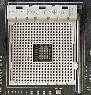
FIGURE 3.4-9 An AMD A4 CPU socket
• Memory compatibility There are four criteria for determining the compatibility between a motherboard and the memory modules to be used:
• Form factor What memory slots are available (DIMM or SO-DIMM)? What DDR generation is supported? Older motherboards typically support DDR3, and newer motherboards support DDR4 or DDR5.
• Capacity The limit on the amount of memory a system supports is determined primarily by the CPU. For example, a motherboard that supports 128 GB may actually be limited to 4 GB by a 32-bit processor. Therefore, be sure to match the memory capacity to the motherboard and CPU.
NOTE To find the memory capacity on a Windows PC, enter the command wmic memphysical get maxcapacity at a command prompt and divide the result by 1,048,576. The result is the maximum memory capacity in gigabytes.
• Chipset Different CPUs support different chipsets. Some chipsets support overclocking and others don’t. A low-performance chipset can restrict the operations of a high-performance CPU, and a fully featured chipset may be wasted on a low-performance CPU. Check with the CPU manufacturer to determine the capability of a motherboard’s chipset with a CPU.
• BIOS/UEFI For a system to function properly, the motherboard, CPU, chipset, and the system BIOS must all be compatible. The motherboard manufacturer’s website should list the compatibility information for the motherboard and the BIOS. A new motherboard should be good to go, but a CPU upgrade may require a BIOS update—before you install the new CPU.
• Fit Some RAM modules require large heat sinks that may obstruct other components, such as the CPU cooling devices. Check that the height and position of the memory modules and the size and position of the CPU cooling devices are able to fit together and function properly.
System Compatibility Issues
Depending on the use or purpose of a system, relatively unique compatibility issues may exist. Servers, desktops, and mobile PCs all have vital considerations when you’re determining the compatibility of a motherboard and other components.
Servers
Like all systems, a motherboard in a server computer must be capable of supporting the demand to be placed on it. However, the two primary considerations for a server motherboard choice are the chipset and the compatibility of the CPU and memory modules. The chipset controls the overall functionality of the motherboard. Also, as discussed earlier, the motherboard, CPU, and memory must all be matched to each other as well as the workload of the server.
Desktops
The compatibility issues of a desktop computer are those described earlier in this section, but like all systems, the key issue is how it will be used. The motherboard, CPU, and memory must all be properly sized and configured to handle the role and purpose of the system. An engineering workstation requires more capabilities than a computer used strictly for records retrieval.
Mobile
Laptops and notebooks are the mobile devices that are capable of major upgrades, but they may not be conducive to upgrading the motherboard, CPU, or memory. The options for upgrades to these components are more limited than those in a server or desktop system. Check the manufacturer’s guidelines on upgrading a mobile device and the compatibility of the devices that can be upgraded.
Multisocket Motherboards
Motherboards with two or more CPUs are generally used by high-end or enterprise systems. Dual-processor motherboards are readily available from the major motherboard manufacturers, but anything beyond that (this is, three, four, or more processors) is less common and typically must be customized. Figure 3.4-10 shows an example of a dual-socket motherboard.
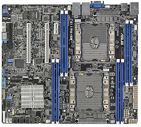
FIGURE 3.4-10 A dual-socket motherboard (image courtesy of ASUSTeK Computer Inc.)
On a multi-CPU system, based on a multiple-socket motherboard, if one processor becomes overloaded, its load is shared with another processor, which makes the entire system more efficient and faster. Compatibility issues mainly involve the CPUs supported and especially the chipset. These elements must be matched to achieve optimal performance of the system. See the motherboard manufacturer for information on what components are compatible and supported.
BIOS/UEFI Settings
The configuration setup utility stored in the system ROM enables you to configure important system settings stored in CMOS. These settings include CPU setup, boot sequence, power management, and several others, which are described next.
CMOS stands for complementary metal-oxide semiconductor, which is the material used to make the chip. CMOS has a very small amount of storage in which the configuration settings for a system are stored, and it requires a power source to retain the data it holds, which is provided by a battery on the motherboard. The term CMOS is most commonly used to refer to the data stored on the chip rather than its material.
NOTE CMOS is an algorithm commonly associated with BIOS and the system configuration of a computer.
BIOS/UEFI
The Basic Input/Output System (BIOS) is stored on a read-only memory (ROM) chip, which also stores the BIOS system and configuration setup utilities. These BIOS utilities are examples of firmware. The system ROM is typically labeled with the BIOS maker’s name but can also be a tiny chip (or a set of two tiny chips) on the motherboard. Some motherboards have two BIOS chips: an M_BIOS and a B_BIOS (see Figure 3.4-11). An M_BIOS is the main or primary BIOS chip, and it’s used during system startup. The B_BIOS is a backup or reserve to the M_BIOS, and it overwrites the M_BIOS chip should it become corrupted.
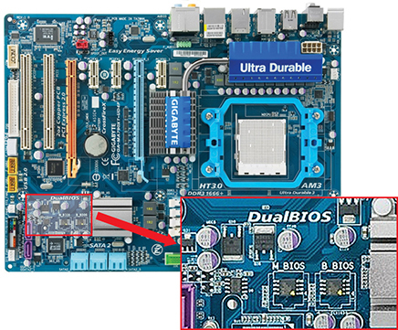
FIGURE 3.4-11 The inset shows a magnification of the M_BIOS and B_BIOS chips.
There’s a big difference between system ROM chips and RAM: RAM is called volatile because it stores data only while it’s powered. ROM is nonvolatile and retains data even when the system isn’t powered. Except for replacing the CMOS battery (described in the next section) if it dies, system ROM requires no specific maintenance.
The firmware on modern systems is the Unified Extensible Firmware Interface (UEFI). Here are the essentials:
• UEFI is often accessed through a graphical system setup utility. Most laptops, notebooks, and desktop PCs also have a text-mode utility for both BIOS and UEFI.
• UEFI supports booting to partitions larger than 2.2 TB.
• The UEFI setup utility can be opened from within the OS, which is something that cannot be done with BIOS.
• UEFI supports a security feature called Secure Boot that ensures a device boots using only trusted software.
NOTE Although it may sound as if BIOS and UEFI are perhaps mutually exclusive, most of the currently available operating systems versions support BIOS and UEFI together.
The BIOS Setup Utility
As stated earlier, the traditional BIOS CMOS configuration setup utility cannot be accessed once a device is fully started and running an OS. Accessing the BIOS configuration utility must be done near the beginning of the system boot process. Depending on the device manufacturer and the BIOS type in use, the method used varies. At one time, a prompt was displayed to let you know which key you needed to press to access the BIOS utility. However, many newer systems no longer do so. The instructions for entering the BIOS configuration utility can be found in the documentation of the motherboard.
Figure 3.4-12 shows an example of the main (opening) tab of a BIOS configuration setup utility. The information displayed by this utility reflects the current configuration of the software and hardware of the system. Most of these settings can be changed and stored to the CMOS and remain in effect unless modified in the future.
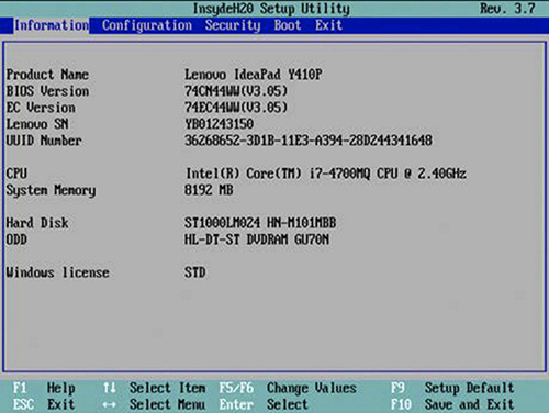
FIGURE 3.4-12 The main menu of a text-based BIOS configuration utility
Today, most configuration setup utilities are graphical user interfaces and mouse-friendly, like the one shown at the top of Figure 3.4-13, rather than the text-mode utilities you must navigate with a keyboard, like the one shown at the bottom of Figure 3.4-13. In either case, both the text and the GUI styles open to a main screen with a good overview of your CPU, RAM, hard drives, and optical drive settings, along with either a series of menu choices or tabs on which specific configuration settings can be accessed, reviewed, and modified.
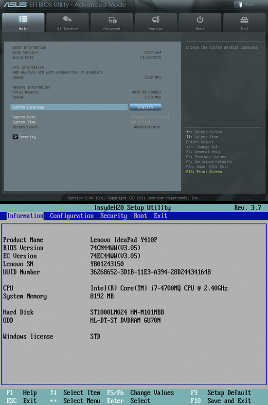
FIGURE 3.4-13 System information screen in graphical (top) and text-mode (bottom) setup utilities
Navigating the CMOS Setup Utility
Although the items listed on the main menu of a text-based utility or the tabs on a GUI utility may not be exactly the same from vendor to vendor, the configuration settings and hardware designations are virtually always the same.
When you’re accessing and working with the configuration utilities, there are two navigation features to keep in mind before you exit a system configuration setup utility, especially if you changed any of the settings:
• Save & Exit Setup To avoid accidents, only use this option when you intend to make a change and you’re certain what the effect will be. Typically, selecting this option brings up a confirmation prompt such as “Are you sure you want to make these changes? Y/N.”
• Exit Without Saving This option discards your changes. Choosing this option brings up another “Are you sure? Y/N” confirmation prompt. Press Y to take your leave of CMOS setup without doing any damage.
NOTE There’s enough variety in how tabs, menus, and options are labeled in different setup utilities that you’ll inevitably find yourself hunting for what you need.
Boot Options
The boot options (see Figure 3.4-14 for an example) hold one of the most frequently changed settings in the setup utility: the boot sequence. This setting decides which devices your system attempts to boot from and in what order. Other options you’re likely to find here dictate whether the system boots from USB devices or network locations, displays detailed POST (power-on self-test) information, displays the key combination to reach the setup utility, and so on.
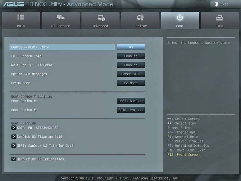
FIGURE 3.4-14 Boot tab in graphical setup utility
EXAM TIP The boot sequence is the first place to check if you have a computer that attempts to boot to an incorrect device or gives an “invalid boot device” error. If you have a USB thumb drive inserted and this setting has removable devices ahead of hard drives in the boot order, the computer will dutifully try to boot from the thumb drive.
USB Permissions
In a variety of situations, it may be necessary to disable access to USB ports to prevent the damage or loss of sensitive data or the introduction of malware through the actions of unauthorized employees or intruders. There are four basic ways to disable USB ports:
• Disabling USB ports in BIOS USB ports can be disabled for any operating system. Open the BIOS, access the Integrated Peripherals tab, and change the status of the USB controller to Disabled. If you wish to enable the USB ports later, just change the setting to Enabled.
• Disabling USB ports in the Device Manager You can use the Device Manager to disable the USB port on your Windows device by selecting the Universal Serial Bus Controller option in the Windows Device Manager, right-clicking the USB device you want to disable, and choosing Disable Device from the pop-up list, as shown in Figure 3.4-15. Another option is to uninstall the device from the Device Manager completely.
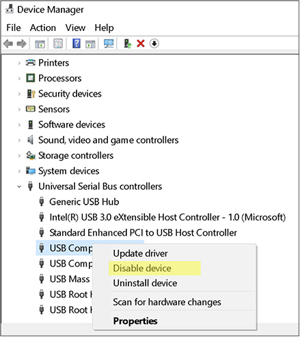
FIGURE 3.4-15 Disabling a USB device on the Device Manager
• Disconnecting the USB This process should be your last resort, unless you want to permanently disable a USB port on a system. While you can’t disable all of the USB devices this way, you can remove one USB port simply by unplugging it from the motherboard.
• Locking USB ports with Registry entries You can disable a USB port using the regedit utility to change its settings in the Windows Registry. In the left pane of the regedit window, navigate to HKEY_LOCAL_MACHINESYSTEMCurrentControlSetServicesUSBSTOR. For this key, double-click the Start option in the right pane. In the Start box, change the value to 4 (Disable). A value of 3 enables the port. Save the entry and exit regedit.
Trusted Platform Module
The Trusted Platform Module (TPM) is a secure microchip that acts as a crypto-processor to provide hardware-based security features. TPM is resistant to malware attempting to alter its security features. TPM creates, stores, and controls cryptographic keys, provides device authentication using a burned-in RSA key, and manages system security metrics and measurements.
During the boot process, TPM “measures” the firmware and OS code and stores the measurements. The TPM measurements benchmark how the system started up and verifies that a TPM-generated key was used in the boot process. TPM keys are used in a variety of ways, including the following:
• Attack mitigation TPM can be configured so that the TPM key is not available outside TPM, which can be used to mitigate malware and phishing attacks.
• Authorization TPM can be configured to require an authentication/authorization code before the TPM keys can be used. Too many bad guesses initiates protection against what TPM sees as a dictionary attack.
• Confidentiality TPM can be configured to protect any data identified by a user.
CompTIA wants you to know about the security options you might find in the BIOS/UEFI setup utility, whether collected on a single tab (see Figure 3.4-16) or scattered about other menus:
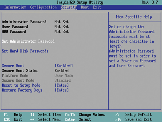
FIGURE 3.4-16 Security tab in text-mode setup utility
• Passwords When a user’s BIOS/UEFI password is set, the system won’t boot without the correct password. An administrator’s BIOS/UEFI password restricts access to the BIOS/UEFI utility itself.
EXAM TIP Remember that BIOS/UEFI configuration settings—including passwords—can be wiped by using the CMOS clear jumper or button or by removing and replacing the CMOS battery.
• Secure Boot This UEFI protocol protects the system from some low-level malware and other exploits by refusing to load driver or OS software that hasn’t been properly signed by a trusted party. Secure Boot requires an Intel CPU, a UEFI BIOS, and an operating system designed for it.
Cross-Reference
More information on TPM is included later in this objective in the section “Encryption.”
Fan Controls
There is a direct relationship between the proper adjustments of the cooling system inside a computer case and the reliable operation of the CPU, motherboard, and all the other internal components of a PC. The operational settings of a PC’s cooling system and case fan(s) are a necessity not only for the immediate operation of the computer but also for its service life.
There are essentially three ways to set the cooling and fan controls on a computer:
• Manufacturer-supplied software Quality cooling system components and case and CPU fans come with software provided by the manufacturer that is specific to the device or component. Since it is specific to a particular device or brand, this software is without compatibility problems and is simple to use.
• BIOS/UEFI settings Virtually all BIOS and UEFI systems provide you with the capability to view and set fan speeds, cooling system temperature targets, and other operational settings.
• Third-party software Third-party system monitoring software, including fan control and monitoring software, can typically be configured to a long list of PC hardware and multiple operating systems. Several third-party fan control and cooling system monitoring packages are available as freeware, demoware, or licensed. Figure 3.4-17 shows the basic user interface for the NoteBook FanControl software.
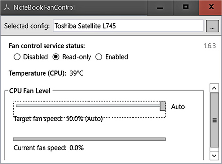
FIGURE 3.4-17 The main page of the NoteBook FanControl software
ADDITIONAL RESOURCES For more information on the popular fan control and monitoring software packages available, navigate to the article “The Ultimate Guide to CPU Temperature” by Miodrag Matović (https://www.thetechlounge.com/cpu-temperature/).
Secure Boot
Secure Boot is a security standard that helps to ensure a device only starts up with firmware and software that the device or operating system manufacturers trust and have approved. Under the Secure Boot process, when the device starts up, firmware verifies the signature of each of the software elements involved in the boot process—including all UEFI and Option ROM firmware and drivers, the operating system, and Extensible Firmware Interface (EFI) drivers—for validity before passing control to the operating system to complete the startup.
There are three levels to a Secure Boot on a Windows system:
• Secure Boot PCs with both UEFI firmware and a TPM can boot using only trusted boot software.
• Trusted boot A Windows PC’s system verifies the validity of each of the startup components before loading it.
• Measured boot As the boot process progresses, its actions are logged. The log of the complete boot process can then be forwarded to a trusted device for an objective analysis of the PC’s health.
Boot Password
A boot password, also commonly referred to as a BIOS password, when configured, controls the access to the CMOS-stored information used by the CPU to start up a computer. In a sense, a boot password serves as an authentication of just who is starting up the system, which in some highly secured areas could be very important.
The downside to configuring a boot password on a system’s BIOS is that forgetting it means no bootup, which can be a real hassle. Some help is available, though: the BIOS provider can expose a backdoor BIOS password, which may require that the firmware be flashed immediately after gaining access. Also, user-created boot passwords can commonly be reset by removing the CMOS battery or by software specifically designed for this purpose.
Encryption
Essentially, encryption is the process used to convert readable cleartext data into garbled, unreadable, undecipherable data. The purpose of this conversion is to ensure that only those authorized to access, read, or use the data are the ones who do so. Of course, this is a simplification, but not by much. Encrypted data is stored, transmitted, and, if unencrypted, used.
The process of encryption takes in plaintext data and encrypts it using an encryption algorithm and an encryption key to produce ciphertext. Ciphertext requires a specific decryption key before it can be viewed or used. There are two basic types of ciphertext: symmetric (private key), which uses the same key for encryption and decryption, and asymmetric (public key), which uses a private (secret) key to encrypt the data and a public key (not secret) to decrypt it.
Using TPM
The use of TPM, also referred to as ISO/IEC 11889, improves the general security of a PC. On a computer, TPM securely creates and stores encryption keys and verifies that the operating system and firmware are valid and have not been damaged or tampered with. Essentially, TPM is used by an operating system to safeguard the user to verify and authenticate the startup and operations of a PC. Windows, Linux, and macOS all implement TPM functions in their security processes.
TPM is a chip installed on a PC motherboard, plugged into the motherboard using a small card, or integrated into the microprocessor on AMD and Intel CPUs. The current version is TPM 2.0, but TPM has been available to PCs since 2005. Any PC manufactured after 2016 is likely to have TPM as a part of its system.
NOTE You can check to see if a Windows 10 PC has TPM. If there is a Security Processor section on the Settings | Update and Security | Windows Security | Device Security page, TPM is available on the system. If Security Processor information is not displayed, check your motherboard or CPU manufacturer’s website for information.
A TPM chip interacts with the security systems on a PC to provide input to the allow/disallow decision. Each time a user logs in to a system, TPM initiates an encryption key to be associated with the user’s session if no problems are detected. However, if a threat, either real or suspected, is detected, the system is locked down as a preventive measure. The security functions of TPM include the creation and storage of encryption keys and device authentication.
Hardware Security Module
A hardware security module (HSM) is used for basically the same function as a TPM. However, the two devices have one major difference: an HSM is a standalone or expansion card insert hardware device (see Figure 3.4-18) instead of a chip on the motherboard. HSMs are intrusion- and tamper-resistant. This makes them an excellent choice for protecting and storing encryption keys that can be securely accessed by authorized users. An HSM controls access and limits the risk of threats to private encryption keys.
FIGURE 3.4-18 A rackmount HSM
HSM is used to secure digital keys and signatures and to encrypt and decrypt documents. HSM can be used for personal security, but it is mostly used in banking, healthcare, and purchase card systems.
CPU Features
CPUs have a variety of features that distinguish them from each other, including the instruction set in use, number of cores, hardware virtualization, encryption, multithreading, and other architecture features, each of which is briefly explained in the following subsections.
x64 and x86 Architectures
Although the terms x86 and x64 are considered by many to be form factors, bus widths, or other technology or design elements of a CPU, they are, in fact, identifiers for instruction set architectures (ISAs). The x in either term represents an ISA version. Both ISAs were developed by the Intel Corporation for its CPUs.
x64 Architecture
The x64 ISA, also referred to as x86-64 or the x86-based 64-bit ISA, is actually a family of ISAs for computer processors. Several manufacturers have developed proprietary 64-bit ISAs. Intel and AMD support Intel 64 and AMD 64, respectively. The x64 ISA has a virtual address space of around 256 tebibytes (TiB, the binary value equivalent of a terabyte) and relative addressing in memory.
Here’s a list of some of the primary features of the x64 ISA:
• A 64-bit integer capability that supports a value range of approximately plus or minus 9 quintillion, or ± 263
• An approximate 256-TiB virtual address space
NOTE A virtual address space (VAS), also known as a logical address space, is a range of virtual memory addresses allocated to a process by the operating system. It represents areas of physical memory and their addresses that are referenced in a relative way by a process.
• A very large file mapping in a process’s address space
• A large physical address space in RAM of up to 256 TiB
Applications of the x64 ISA include the following:
• Mobile processors
• Supercomputers
• Current operating systems
• Video games consoles
• Virtualization technologies
x86 Architecture
The x86 ISA defines how a processor manages and executes various instructions from an operating system and application programs. The x86 ISA is based on Intel’s 8086 and 8088 microprocessors and grew from a 16-bit instruction set (for the 16-bit processors) to a 32-bit instruction set. The x86 ISA is based on the complex instruction set computing (CISC) architecture. Complex instructions are executed one at a time and nearly all take more than one cycle to complete. The x86 ISA has been adopted by various microprocessor manufacturers because of its compatibility with PCs to Supercomputers.
The following lists some of the primary features of the x86 ISA:
• Uses CISC computing architecture
• Optimizes system performance using a hardware approach
• Uses more registers and less memory for operations
• Designed for complex addresses
Some applications of the x86 ISA are:
• Mobile devices and PCs
• Gaming consoles
• Workstations running specific processing-intensive applications (intensive workstations)
• Cloud computing segments
Advanced RISC Machine
A reduced instruction set computer (RISC) uses a smaller, optimized instruction set, as opposed to a CISC. Of the two, RISC is the more efficient and is used by many of the current CPUs. However, when a need arose for a low-cost, efficient 32-bit RISC CPU that could be used in embedded control systems, digital signal processors (DSPs), and portable multimedia devices, the condensed Advanced RISC Machine (ARM) instruction set was developed. ARM is orthogonal, meaning that all instructions are in a standard format and use the same addressing scheme for all addressable registers and resources, which is a feature of all RISC CPUs. ARM processors are common to smartphones, tablets, and other handheld computing and communication devices.
Single Core and Multicore
Originally, all CPUs had only one processor core. In fact, it wasn’t even called a core. However, when CPU clock speeds hit the practical limit of roughly 4 GHz, CPU producers combined two or more CPUs (cores) onto a single processor die to create multicore CPUs. The first multicore processors combined two CPU cores onto one microprocessor integrated circuit (IC) in a dual-core architecture. When combined onto a multicore microprocessor, each discrete core has its own resources.
EXAM TIP For the A+ Core 1 exam, know the basic differences between a single-core CPU and a multicore CPU.
ADDITIONAL RESOURCES To access information on the microprocessor (and much more) in a computer, you can use the CPU-Z utility (https://www.cpuid.com/softwares/cpu-z.html).
Multithreading
Virtually all of the multicore CPUs process multiple threads, which is called multithreading (the execution of more than one thread simultaneously). A thread is essentially a basic unit of a process, and a process is a running program that can have multiple threads.
There are basically two types of threads execution:
• Concurrent execution The processor allocates and switches resources from one thread of a multithreaded process to another, as needed.
• Parallel execution The separate threads of a process run on different processors in parallel.
Multithreaded processes can use one of three types of process approaches:
• Many to many Multiple threads interact with an equal or lesser number of threads.
• Many to one Multiple threads are linked to a single thread.
• One to one With this approach, one thread is linked to just one other thread.
Hardware Virtualization
Intel and AMD have built-in support for hardware virtualization: Intel’s Virtual Technology Extensions (VT-X) and AMD’s AMD-V and Secure Virtual Machine (SVM). Although supported on different CPUs, these extensions essentially work the same.
Hardware virtualization (also called hardware-assisted virtualization or native virtualization) is enabled by an expanded instruction set on the Intel and AMD processors. The processor provides a logical structure for defining a virtual environment on a computer. Hardware virtualization is enabled through BIOS/UEFI firmware.
Enabling Hardware Virtualization
If hardware virtualization is not enabled on a PC, one or both of the following conditions or messages will appear:
• The PC doesn’t have either VT-x or AMD-V hardware acceleration, or it is not available on the system.
• This computer doesn’t have VT-x/AMD-V enabled.
Should one of these or a similar message appear, provided your system has one of the hardware virtualization technologies available (we discuss how you can check this next), you can use one of the following processes (whichever is appropriate) to find and enable hardware virtualization:
• Boot the PC into its BIOS or UEFI setup configuration utility.
• Locate the Virtualization settings (often located under System Configuration).
• Enable the Hardware Virtualization and the save and exit.
Verifying Hardware Virtualization Is Enabled on a Windows System
On a Windows system, you can check if hardware virtualization is enabled using a variety of methods. Here are two you can use on a Windows system:
• systeminfo At a command prompt, enter the command systeminfo. Toward the bottom of the information displayed, find the section labeled “Hyper-V Requirements” (see Figure 3.4-19). If the “Virtualization Enabled in Firmware:” is “No,” access the BIOS/UEFI settings to enable this feature.
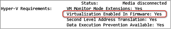
FIGURE 3.4-19 The Hyper-V Requirements section of a systeminfo command’s output
• Task Manager Open the Task Manager from Power User menu or use CTRL-ALT-DEL and choose Task Manager. Click the Performance tab. In the lower-right corner of the Performance windows, the status of Virtualization is shown.
Verifying Hardware Virtualization Is Enabled on a Linux System
To check the status of hardware virtualization on a Linux system, use the following series of commands at the command prompt:
1. Install the cpu-checker utility:
![]()
2. Check the hardware virtualization status:
$ kvm-ok
If the PC has hardware virtualization enabled, a message to the effect that it exists or can be used is displayed.
Cross-Reference
For a comprehensive overview of virtualization, see Domain 4.0 in this book.
Expansion Cards
Although most current motherboards and systems include many built-in ports, there are still some functions and features that can be added to a computer to improve them over the standard defaults available. For example, audio/visual functions are commonly upgraded with expansion cards. The A+ Core 1 exam focuses on expansion cards in Windows systems, although expansion cards are supported by macOS and Linux systems as well.
Video Cards
A video card (or display adapter) handles the video chores within computing devices by processing information from the CPU and sending it to the display. It is configured the same way whether it is an onboard graphics processing unit (GPU) that is a part of the CPU or an expansion card.
Onboard
An onboard video card uses a GPU commonly integrated onto CPUs. Almost all laptops and thick and thin client desktops use onboard graphics support. Desktop computers with onboard GPUs typically have one or more video ports available, as shown earlier in Figure 3.4-2.
Add-on Card
A video/graphics card that inserts into a PCIe slot is one type of what CompTIA refers to as an add-on card. Video cards typically require additional power over what the expansion slot provides. A midrange PCIe video cards uses a 6-pin PCIe power connector commonly located at the top-front edge of the card (the end pointing away from the card bracket). High-end cards use an 8-pin version or, in some cases, two PCIe cables. Figure 3.4-20 illustrates a PCIe video card with a 6-pin power connector and a 6/8-pin PCIe power cable.
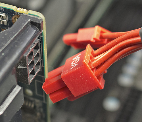
FIGURE 3.4-20 Connecting a PCIe power cable to a PCIe video card
The main parts of a video card are the video RAM and video processor. The video processor takes information from the video RAM and shoots it out to the monitor. Early video processors were little more than an intermediary between the CPU and video RAM, but powerful modern video cards need fans to cool their video processors (see Figure 3.4-21).
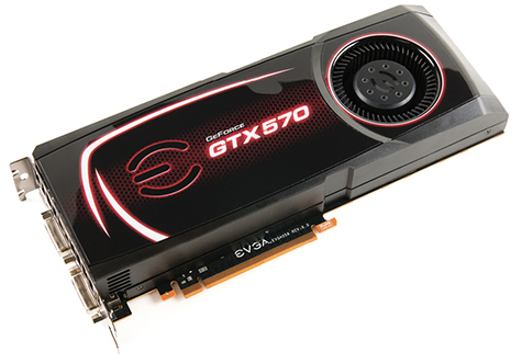
FIGURE 3.4-21 Video card with a cooling fan
When installing a video card into a Windows system, you must also install video device drivers and use the Device Manager to confirm that it works. The next step is to configure the video card in the Display Control Panel applet or using first-party software included with the card.
Sound Cards
For the most part, computers use sound chips built into the motherboard that aren’t necessarily of the highest technology or quality. In fact, embedded sound production devices may have an audible hum or buzz caused by external interference or interference from other devices on the motherboard, especially when heard through headphones. A sound card that produces a higher sound quality is a frequent addition to a computer to improve its sound production with audio speaker sets like those shown in Figure 3.4-22.
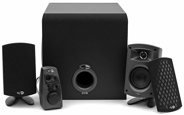
FIGURE 3.4-22 Klipsch 2.1 speaker set
NOTE The numbers used to describe speaker sets, such as 2.1, 5.1, and 7.1, define the number of satellite speakers and a subwoofer. A 2.1 system, for example, means two satellites and a subwoofer. A 5.1 set, in contrast, has two front satellites, two rear satellites (for surround sound), a center channel speaker, and a subwoofer. A 7.1 set adds two additional rear satellites for sound effects to the speaker configuration used for 5.1 surround sound.
Install a sound card like you would any expansion card. Plug audio cables into the correct ports, and they should work fine. If you don’t see errors but get no sound, check the Sound applet in the Windows Control Panel to confirm that the correct devices are working, connected, and set to their defaults and that the playback indicator shows activity on the correct device.
The 3.4-mm audio ports on the motherboard port cluster or sound card bracket aren’t the only audio output. The ports you might find include S/PDIF (Sony/Philips Digital Interface) optical or digital ports, HDMI (High-Definition Multimedia Interface), and DisplayPort HD video ports, which also output HD audio.
Capture Card
A capture card is either an internal expansion card or a peripheral device that records (captures) the display images and content and then formats them for playback as a livestream or a high-resolution video file. Capture cards are classified as input devices, despite the fact they are, as the name states, capture devices. A common use is to capture the video from video game consoles as well as computer video and camera images.
External capture cards are connected to a computer through USB and USB-C or Thunderbolt. A capture card expansion module is inserted into a PCIe slot. Figure 3.4-23 shows examples of capture card devices.
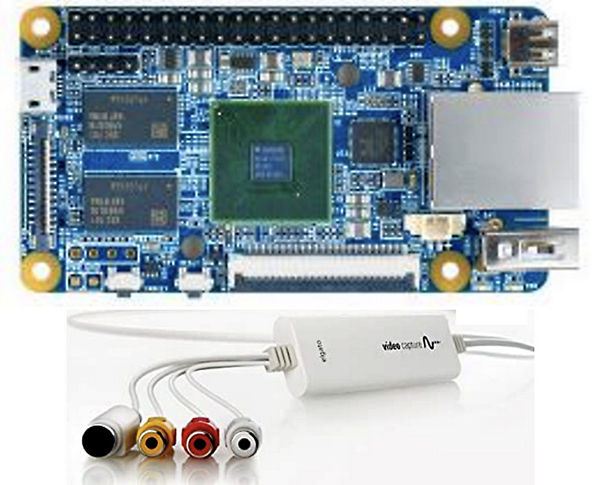
FIGURE 3.4-23 A PCIe capture card (top) and a Thunderbolt video capture device (bottom)
Network Interface Card
The network interface card (NIC), also called a network adapter, links a device to a network infrastructure. Virtually all current PCs and network-capable devices have an onboard port for a network connection. However, some devices, such as tablets and other handheld devices, can use a peripheral device to connect and interact with an Ethernet network. Notebook and desktop computers can also use peripheral network connections, but for other reasons, such as support for faster speeds or to connect to a fiber optic network.
A Windows system will automatically detect and configure a NIC. On some Windows systems and on Linux and macOS systems, you may need to install and configure an expansion card NIC, following the manufacturer’s instructions.
Cross-Reference
To learn more about NIC configuration, see Domain 2.0, Objective 2.2.
Technically, a computing device or a network-enabled device doesn’t communicate directly with the network. The networked device interacts with the NIC, and the NIC places network messages on the network medium. To read the message, the receiving node interacts with its NIC.
Ethernet NICs have LED status indicators (also called link lights) used to display the condition of the link or to confirm a connection. Most NICs have two LEDs, but some can have three: a link or connection light, an activity light, and possibly a speed light if there are three LEDs on the NIC, as detailed in the following list:
• Link light This indicates whether a network connection has been established between the NIC and the network. If the link light is showing green, all is well. However, if the LED is unlit, there is a connection problem.
• Activity light This LED indicates an interaction between the NIC and the network by flickering or flashing intermittently. If this indicator is flashing too fast, there could be a problem with the connection or something on the network.
• Speed light If present, this light indicates the transmission speed of the connection. This LED is found on some 10/100 Mbps Ethernet NICs.
Also, some NICs use two- or three-color LEDs (green, red, and amber) to combine the status lights and other legacy cards (mostly PCMCIA) that have no LEDs at all. Most of the LEDs are integrated into the RJ-45 port, as shown in Figure 3.4-24. There aren’t any real standards for this, but one LED lit up usually indicates the connection status, and all lights shining bright likely means there’s no physical connection. To be sure, consult the motherboard or NIC manual.
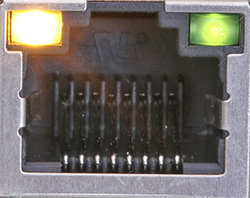
FIGURE 3.4-24 An Ethernet RJ-45 port with LED status lights
Cooling Mechanism
CPUs have no moving parts, at least none you can see with your naked eye, but even so, they generate a considerable amount of heat. Extreme heat is a big problem to a CPU and many other of a PC’s components. Excessive heat causes system instability, lockups, and even dead CPUs. For the most part, CPU packages are made from high-tech thermal plastics and ceramics that dissipate heat, but additional cooling is needed from what is called active cooling. Active cooling has several forms, but the most common are a combination of a heat sink and fan assembly (see Figure 3.4-25) and a liquid cooling system.
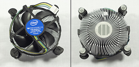
FIGURE 3.4-25 Top of retail heat sink (left) and bottom of fan assembly (right) for an Intel CPU
Heat Sink and Cooling Fans
Unlike the CPU socket, mounting heat sink and fan assemblies properly takes more force than you’d expect! A small flathead screwdriver will help.
EXAM TIP Some systems are fanless or use passive cooling. Smartphones and tablets are the passively cooled devices you’re most likely familiar with. Passive CPU heat sinks may still rely on other fans to create good airflow in the case.
Heat sink and fan assemblies for CPUs usually come as a unit; if not, attach the fan to the heat sink before installing both onto the CPU. Again, different CPUs, socket designs, and heat sinks require different installation procedures, so be sure to read the CPU or motherboard documentation before removing cooling devices from or installing them on the CPU or motherboard. Perhaps the most important operational maintenance components in a PC are the parts that make up the direct cooling system of its CPU. The basic parts in the CPU cooling assembly are a heat sink, a cooling fan, and a paste or sealant material to hold the assembly together. Let’s look at each of these components.
Heat Sinks
A heat sink is essentially the cooling device for the CPU and the component that directly impacts the running temperature of the CPU. Table 3.4-2 compares the various operating temperatures of AMD and Intel CPUs. For each of the CPUs included in the table, the running temperatures are a range of values that represent the temperature of the CPU under light to heavy loads. The maximum temperature is the threshold beyond which the CPU could be damaged.
TABLE 3.4-2 Comparison of CPU Temperatures
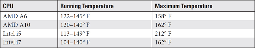
NOTE The temperatures for any give CPU version can vary based on its build and included technologies. The values shown in Table 3.4-2 are averages for the CPU families given.
A CPU heatsink is generally an engineered aluminum or copper block with fins that serves to draw heat up and away from the CPU and dissipate it into the air flowing to and around the fins. Figure 3.4-26 shows a sampling of various types of CPU heatsinks. In each of the heatsinks shown in this figure, notice the fins and the air gaps between them.
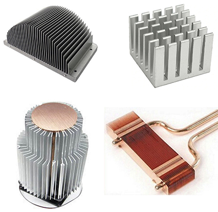
FIGURE 3.4-26 Heatsinks are available in a variety of designs, shapes, and sizes.
There are three primary types of heatsinks used with CPUs, each with some advantages and disadvantages, depending on how and where they are used:
• Active heatsink This type of heatsink has a fan or blower incorporated into it. The assemblies shown in Figure 3.4-25 are examples of active heatsinks.
• Passive heatsink This type of heatsink has no moving parts and uses convection to dissipate heat. The samples shown in Figure 3.4-26 are passive heatsinks.
• Hybrid heatsink As you might guess, a hybrid heatsink combines the capabilities of active and passive heatsinks.
On today’s PCs, in order for any heatsink to be an effective cooling device for a CPU, it must be combined with a cooling fan. Active heatsinks include a fan by definition, but passive and hybrid heatsinks must be combined with a fan to reduce the heat they absorb. However, the heatsink is also assisted in its heat dissipation through the use of a thermal conductor, which is typically either thermal paste or a thermal pad.
Thermal Conductors
The primary purpose of thermal conductors is to remove any air gaps between the heatsink and the cooling fan. Two types of thermal conductors are predominantly used: thermal conductive paste and thermal gap pads, which provide thermal conductivity and thermal impedance, respectively. Conductivity is the transference of heat, and impedance is the efficiency with which the heat is transferred. Thermal conductor materials are generally grouped together as thermal interface material (TIM).
Thermal Pads Officially known as thermal gap pads, thermal pads conform to the space between the heatsink and the cooling fan to fill any gaps. The pads are typically fiberglass and aluminum, with a thickness of between 0.01 and 0.2 inches. Thermal pads are easily installed and don’t require adhesive or thermal paste. In addition to being used as a part of a CPU cooling assembly, thermal pads can also be used to dissipate heat from chips and other components mounted on the motherboard, as illustrated in Figure 3.4-27. Manufacturers of active heatsinks, which include the heatsink and a cooling fan, include a thermal pad because they don’t need adhesion and stay in place without it.
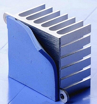
FIGURE 3.4-27 A CPU heatsink with a thermal pad
NOTE Thermal pads are definitely one-time use.
Thermal Paste Officially thermal conductive paste, thermal paste is used for the same purpose as a thermal pad, but because it is basically a liquid, it works differently. Thermal paste is a conductive material that is used to fill the extremely small gaps, often microscopic in size, between a CPU or a graphics processing unit (GPU) and a cooling assembly. The purpose of the thermal paste is to prevent air, which is a conductor of heat, from being trapped and reducing the effectiveness of the cooling system. Thermal paste is typically silicon-, ceramics-, or metal-based.
Thermal paste is applied from an injector (see Figure 3.4-28) to the surfaces to be sealed before they are combined. The application process is a bit different for circular and squarish cooling devices being attached to the CPU or a GPU. For a circular assembly, a small dot of thermal paste is applied in the center of the base of the cooling device. The amount of paste should be about the size of a grain of rice. Anything more may result in paste getting on the motherboard. For the squarish assembly, the most effective method is to place a small amount of thermal paste on the base of the cooling assembly and use a plastic bag or finger cover to spread the paste evenly across the base of the cooler. In either case, be sure that the area that will be in contact with the CPU is evenly covered. The rule of thumb is that the paste should barely cover the area to be sealed.
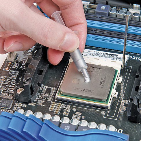
FIGURE 3.4-28 A small amount of thermal paste applied to a CPU cooling assembly
A few other TIMs are available for sealing the CPU and cooling system, including thermal grease, thermal adhesive, thermal gap filler, thermal tape, phase-change materials, and liquid metals. Each of these materials has its advantages and disadvantages, but they all fulfill essentially the same purpose as thermal paste and thermal pads.
Liquid Cooling System
As discussed earlier, there is a maximum temperature that a CPU can reach before it may be damaged by that heat. Most systems implement what is called thermal throttling, which means the processor reduces its performance to prevent excessive overheating. An alternative cooling method that helps to prevent both the damage and the reduction of performance is liquid cooling.
Your car has a liquid cooling system, and the ones installed in computers work essentially the same. A liquid is circulated through a heatsink attached to the CPU. The cooler liquid passing through the heatsink, absorbs the heat, and the now hot liquid flows to a radiator. The radiator transfers the heat from the liquid to outside the case, thus cooling the liquid, which then flows back through the system.
Two types of liquid cooling systems are popular for PCs: all-in-one (AIO) coolers and custom loop coolers. AIO cooling systems are the most common of the two and the most likely type you will encounter on the A+ Core 1 exam. An AIO system includes a block that has a pump that attaches to the CPU. From this assembly, two tubes attach to a radiator that has a fan to cool the liquid. Figure 3.4-29 illustrates the major parts of a liquid cooling system in a PC.
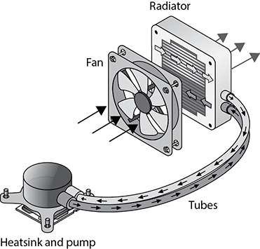
FIGURE 3.4-29 The components of a PC liquid cooling system (image courtesy of Intel Corporation)
REVIEW
Objective 3.4: Given a scenario, install and configure motherboards, central processing units (CPUs), and add-on cards
• Motherboards have port clusters at the rear for USB ports, audio jacks, network ports, and other built-in ports.
• PCI slots have been for the most part replaced by PCIe slots that use ×1 to ×16 lanes.
• Intel and AMD CPUs are not interchangeable.
• Most hard drives and optical drives connect to SATA ports.
• A motherboard header is a motherboard socket for adding connection ports.
• The M.2 standard supports both SATA and PCIe but can be used in only one at a time.
• CPU/motherboard compatibility elements are manufacturer, CPU socket type, memory compatibility and capacity, form factor, and chipset.
• Dual-processor motherboards are generally used by high-end or enterprise systems.
• The BIOS/UEFI utilities are firmware, and the configuration settings are stored on CMOS.
• USB ports may be disabled to protect sensitive information.
• TPM creates, stores, and controls encryption keys as well as manages system security metrics.
• Secure Boot ensures a device starts up with trusted firmware and software.
• A boot password controls access to CMOS-stored information.
• Encryption converts cleartext into undecipherable data to ensure only authorized access.
• HSM is a hardware device for protecting and storing encryption keys.
• The x64 and x86 ISAs are 64- and 32-bit processor and PC architectures, respectively.
• A RISC is an optimized instruction set, and an ARM has a standardized instruction set.
• Intel VT-x and AMD-V provide hardware virtualization support.
• Video cards use faster RAM than motherboards, and most have cooling fans.
• Most video cards require extra power from a PCIe power connector.
• Sound cards and onboard sound chips support stereo or surround audio.
• HDMI and DisplayPort output digital audio.
• NICs have status lights to indicate connection and speed.
• USB expansion cards and header cables enable you to add more USB ports.
• A heatsink is a cooling device of aluminum or copper that draws heat away from a CPU.
• The two types of thermal conductors are thermal conductive paste and thermal gap pads.
• Liquid cooling circulates liquid to cool CPUs.
3.4 QUESTIONS
1. You have been tasked with reviewing motherboard form factors for a project. The number-one requirement is that the motherboard be as small as possible. Which of these motherboards is the smallest?
A. Micro-ATX
B. Mini-ITX
C. ITX
D. ATX
2. Your client has selected PCIe version 3.0 graphics cards to refresh the organization’s video editing workstations. However, the systems support PCIe version 2.0. Which of the following statements is true?
A. The cards will run at PCIe 3.0 speeds.
B. The motherboards must be replaced with PCIe 3.0–compatible versions.
C. The cards cannot be used.
D. The cards will run at PCIe 2.0 speeds.
3. You are upgrading your personal system with USB 3.0 (USB 3.1 Gen 1) devices but have run out of external ports. You need two more ports. Which of the following would provide these ports?
A. USB 2.0 header cable
B. USB-C header cable
C. USB 3.0 header cable
D. SATA-to-USB conversion cable
4. You are creating documentation for other technicians to use as they configure the UEFI firmware on new systems. Which of the following statements should not be in the documentation because it is incorrect?
A. SATA drives cannot be configured as hot-swappable.
B. USB ports can be disabled.
C. The boot sequence can be changed.
D. You can exit UEFI/BIOS setup without saving changes.
5. Which of the following is not a material used to seal a CPU cooling system?
A. Thermal paste
B. Thermal pad
C. Liquid metal
D. Thermal foam
3.4 ANSWERS
1. B The Mini-ITX (mITX) is the smallest motherboard listed.
2. D When two different PCIe versions are present (slot and card), the slower version is used.
3. C A USB 3.0 header cable provides two USB 3.0 ports; however, not all motherboards with USB 3.0 have headers.
4. A SATA drives are hot-swappable when configured as AHCI in the UEFI/BIOS firmware.
5. D Thermal paste, thermal pads, liquid metal are all materials that can be used to seal gaps in a CPU cooling system. Thermal foam is not developed for this purpose.
 Given a scenario, install or replace the appropriate power supply
Power supply units (PSUs) provide the electricity that enables computers to run. PSUs are a common reason for PC failures, yet they are often neglected and not included in preventive maintenance programs. As port-powered peripherals such as universal serial bus (USB) devices become more numerous and CPUs and GPUs require more power, PSUs with larger wattage ratings are more in demand.
Input: 110–120 VAC vs. 220–240 VAC
A desktop computer includes a PSU (see Figure 3.5-1) that converts high-voltage AC (alternating current) power to the low-voltage DC (direct current) power for the computer’s motherboard and devices. Its internal fan also helps cool the components and drives. When connected to a properly grounded outlet, the power supply also provides grounding for all the other equipment inside the case.
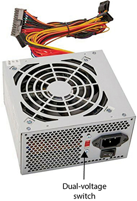
FIGURE 3.5-1 An ATX 500-watt power supply
The standard AC voltage in the U.S., Canada, Mexico, and 34 other nations is between 110 volts (V) and 120 V, which is commonly referred to in the U.S. as ~115 volts AC (VAC). In the remaining 175 or so countries of the world, the standard AC voltage ranges from 220 VAC to 240 VAC. Because of the difference in the standard voltages, many power supplies include the capability to use a dual-voltage switch to select the voltage appropriate to a certain location. The red slide switch on the back of the PSU shown in Figure 3.5-1 is a dual-voltage selector.

CAUTION Even if the plug pattern and the outlet are compatible, plugging a 110-V device into a 220-V outlet would cause the device to run up to about twice its designed operations and burn out fairly quickly. On the other hand, if you were to plug a 220-V device into a 110-V outlet, the device may run for a while but will eventually stop.
EXAM TIP For the A+ Core 1 exam, you should know that a PSU can be switched between the two primary electrical voltage range services.
PSU Terminology
The terminology used to describe the electrical capabilities of a PC PSU can be confusing. A PSU can be fixed input, switching dual-output, fixed output, or multiple output voltage devices. Typically, a standard desktop computer includes a fixed input/fixed output PSU. This means that the power supply will produce a single voltage that won’t change—it is fixed at that voltage. Like the one shown in Figure 3.5-1, a PSU that can be switched between voltage inputs is known as a switched input device. However, it can be confusing that a switched input PSU can also be a fixed input PSU, because once a single voltage service input is selected, the PSU is a fixed input device.
Most current power supplies are auto-switching, meaning that they will detect the incoming voltage and configure themselves accordingly. You can use an auto-switching power supply anywhere in the world, from the 110–120 VAC in New York City to the 220–240 VAC in Hong Kong. This is especially important with portable computers!
CAUTION If you are using a fixed input power supply connected to a 220–240 VAC power line, don’t turn it on if the voltage selector switch is set to 115 VAC. That’s a sure way to kill the power supply and possibly other components as well!
EXAM TIP The power connector for the AC plug on the back of a power supply is called an IEC-320 connector, and you should expect to see a question on the CompTIA A+ Core 1 exam that refers to the power supply unit as a PSU.
Output: +3.3 V, +5 V, and +12 V
PC PSUs vary in their output, efficiency, and the number of +12-V rails used. A power supply rail is a path on a PSU’s printed circuit board (PCB). A PSU rail inputs AC power from an external source and transforms it into DC power that is output to cables connected to internally powered devices.
In virtually all PSUs, there are rails for +3.3 V, +5 V, and +12 V. Three different voltages are needed because not all PC hardware devices require the same power to operate. For example, the USB ports operate on 5 V, DDR4 RAM requires only between +1.2 and +1.35 V, and the case fan runs on +12 V, as does the CPU. The job of the PSU is to provide the appropriate power levels required by each of the PC’s components.
Regardless of whether the incoming power is at 120 VAC or 220 VAC, it must be converted to both direct current (DC) and, initially, +12 V, which is the standard voltage with which a PSU works. This conversion is performed by the AC/DC converter in the PSU. A portion of the +12-V power flows to +3.3-V and +5-V converters, completing the conversion of the AC power source into the three rails of the PSU. Earlier it was mentioned that DDR RAM needs only +1.2 V or +1.35 V of power, but the lowest voltage produced by the PSU is +3.3 V. To deal with this, most motherboards, especially the newest models, have power regulators as well as converters to refine the power to the needs of the components mounted on them.
The +12-V rail is the source of power to the CPU and possibly the GPU. It’s common in recent PSUs that the +12-V rail is divided into two or more rails to reduce the amperage (amps) each carries for safety reasons. A single-rail power supply is usually enough for an average desktop computer, but a high-end system may require a multi-rail power supply. In practice, avoid running too many devices off one rail in a multi-rail power supply.
EXAM TIP Make sure you know the voltage ranges of input (110–120 VAC and 220–240 VAC) and output (+3.3 V, +5 V, and +12 V) supported by power supplies.
ADDITIONAL RESOURCES To learn more about the internal components and the operations of a PSU, read the article “Anatomy of a Power Supply Unit (PSU)” at https://www.techspot.com/article/1967-anatomy-psu/.
Output: +5 V and +12 V Connectors
As described earlier, a PSU converts high-voltage AC to low-voltage DC in order to provide the appropriate power levels for the motors on hard drives and optical drives (+12 V) and onboard electronics (+5 V) via the device cables that are integrated into the PSU.
The device cables and connectors common to most PSUs are serial ATA (SATA) and Molex, as shown in Figure 3.5-2. Higher-end power supplies have a dedicated 6- or 8-wire PCIe connector for PCI Express video cards (see Figure 3.5-3).
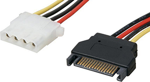
FIGURE 3.5-2 Molex (left) and SATA (right) power connectors
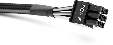
FIGURE 3.5-3 PCIe power connector
Power supplies connect to the motherboard with either a 20-pin or 24-pin P1 connector on the primary power circuit and then a 4-wire P4 secondary power connector or an 8-wire EPS12V power connector to supply power to the CPU (see Figure 3.5-4). The EPS12V connectors use one 4-pin (P4) connector on motherboards that use a 4-pin ATX12V connector and use both on motherboards that use an 8-pin EPS12V connector.
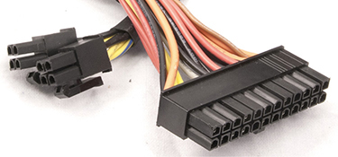
FIGURE 3.5-4 EPS12V/ATX12V connectors (left) and P1 connector (right)
EXAM TIP The +5-V orange (sometimes gray) wire on the P1 connector is called power good and is used in the initial boot sequence.
Many modern ATX motherboards use an 8-pin CPU power connector, variously referred to as EPS12V, EATX12V, or ATX12V 2×4. Half of this connector will be pin-compatible with the P4 power connector; the other half may be under a protective cap. On any computer, check the motherboard’s installation manual for when to use the full 8 pins. For backward compatibility, some power supplies provide an 8-pin power connector that can split into two 4-pin sets, one of which is the P4 connector (refer to Figure 3.5-4). Although they look similar, the 8-pin CPU power connector is not compatible with the 8-pin PCIe power connector. Table 3.5-1 lists the common connectors of the ATX12V power supplies—the current standard—with their voltages and uses.
TABLE 3.5-1 Power Connectors and Voltages
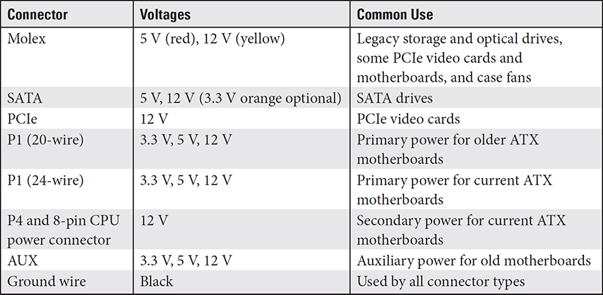
CAUTION Power connectors are keyed so that you can’t easily plug them in backward, but some older designs can be forced. Reversing the power on a device will fry it. Don’t force a power connector.
24-Pin Motherboard Adapter
To enable the same power supply model to work with older 20-pin ATX motherboards and modern motherboards that use 24-pin connectors, some vendors provide 24-pin motherboard adapters.
Redundant Power Supplies
The name redundant power supply may seem like this device isn’t really necessary, which is ironic because its purpose is just the opposite. A redundant power supply configuration involves a single device, almost always a rack-mounted device, that operates with two PSUs. The two PSUs are both fully capable of powering the device. In normal operation, each of the power supplies provides an equal portion of the power to a connected device. In most cases, there are two devices sharing the load and providing the redundancy, but more PSUs can be interconnected in the redundant grouping. Figure 3.5-5 shows a dual-PSU redundant power supply.
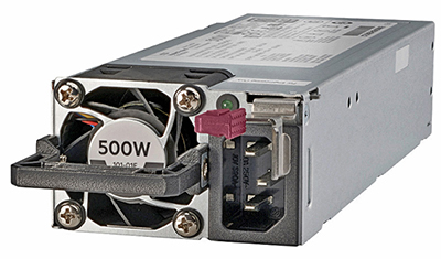
FIGURE 3.5-5 A redundant power supply unit (image courtesy of Hewlett-Packard Enterprises)
Staying with the set of two PSUs, if one of the PSUs is turned off or fails for any reason, the other PSU is powered and connected to provide full power on demand. This redundancy avoids downtime for the powered device.
Modular Power Supply
A standard (typically ATX) PSU will almost always have a few extra unused cables hanging about inside the system case. All of these cables are integrated into the PSU circuitry and cannot be eliminated without damaging them. A module power supply eliminates this problem by providing outlets that are used only if needed. Plus, there are a few other advantages to using modular power supplies, which we’ll get to later.
The two types of modular PSUs are the fully modular and the semi-modular units. Essentially, the difference between them is that every cable that plugs into the fully modular unit can also be removed. A fully modular PSU, like the one shown in Figure 3.5-6, has a series of standard outlets, typically arranged by the output power voltages, into which an adapter cable can be plugged and used to connect to a powered device.
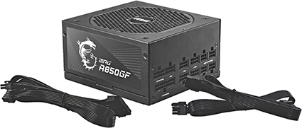
FIGURE 3.5-6 A fully modular power supply with two examples of its cabling (image courtesy of Micro-Star International)
Whereas the fully modular PSU has no permanently attached cables. a semi-modular PSU has integrated cables for the devices that are common to virtually all PCs, such as a 24-pin ATX, 4/8-pin CPU, and maybe PCIe for the motherboard, CPU, and memory. Other cables may or may not be needed for a particular PC, such as cables with SATA, PCIe, or Molex connectors.
Wattage Rating
You may run into questions on the A+ Core 1 exam regarding the differences among volts, amps, and watts. Therefore, you should have some understanding of each and how it relates to the others. To that end, here is a basic description of these terms:
• Volts Voltage (V) measures the electrical pressure of the charge on a medium. It’s something like the pressure of water in a hose.
• Amps Amperage (A) measures the amount of electricity flowing through the medium. Sticking with the water hose example, an amp is like the gallons per minute (gpm) pressure of the water in the hose.
• Watts Wattage (W) measures the amount of electricity needed to operate or power an electrical device. Watts are calculated as A × V = W. To complete the water analogy, watts would measure the force of the water required to fill a water balloon.
Power supplies provide a certain wattage that the motherboard, drives, and fans draw on to run. That’s the desired output. Power supplies also produce harmonics (the hum you hear when the power supply runs), which can cause problems with the power supply and other electrical devices on the circuit if not controlled.
EXAM TIP Wattage is the amount of amperage flowing at a specific voltage, usually written as W = V × A.
A computer requires sufficient wattage to run properly. Every device in the system also requires a certain wattage to function. For example, a typical magnetic hard drive draws 15 W of power when accessed (SSDs use less), whereas a quad-core Intel i9-9900K CPU draws a whopping 162 W at peak usage—with average usage around 92 W. The total combined wattage needs of all devices is the minimum you need the power supply to provide.
If the power supply can’t produce the wattage needed by a system, that computer won’t work properly. Because most devices in the system require maximum wattage when starting, the typical outcome of insufficient wattage is a paperweight that looks like a computer. The only fix for this situation is to remove the device or get a power supply with more wattage. Today’s systems require at least 500-plus-watt power supplies to function.
Good computer power supplies come with active power factor correction (active PFC), which is extra circuitry that evens out high-voltage AC power before passing it to the main power supply circuits, thus eliminating harmonics. Avoid any old and poor power supplies without this circuitry.
Number of Devices/Types of Devices to Be Powered
It’s essential to know the number and types of devices that require power and the electrical properties needed before installing a new power supply in a PC. Power supplies vary in the number of Molex, SATA, and mini (Berg) connectors provided. In fact, some PSUs support only a single PCIe power connector. Molex connectors are no longer used for drives but are used for case fans when there aren’t sufficient fan ports on the motherboard. Molex connectors can also be adapted to run SATA drives or devices that use mini (Berg) connectors.
Avoid using splitters to run more devices than can be connected directly to a power supply. Cheap splitters that use thin wires can overheat, and even the best-quality splitters can introduce points of potential failure into a system.
Power Supply Installation Notes
Be careful when you work with power supplies or inside a computer. Here’s why: an ATX power supply never turns off. If an ATX power supply is connected to AC power, the PSU feeds 5 VDC to the motherboard. Installing cards, chips, or memory modules to a motherboard while power is flowing could damage those components. Remember to always unplug the power supply and wait about ten seconds before you work inside the computer or disconnect the power supply for replacement!
Before you connect the power supply, you’ll need to mount it inside the case with four standard case screws (see Figure 3.5-7). The only exceptions are some small or proprietary cases.
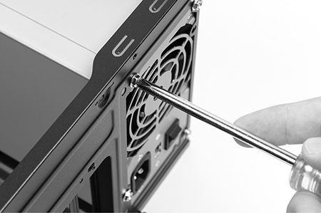
FIGURE 3.5-7 Power supply secured in the case
REVIEW
Objective 3.5: Given a scenario, install or replace the appropriate power supply
• Power supplies support 110–120 VAC and 220–240 VAC, either through a sliding switch or with internal auto-switching.
• The IEC-320 connector is used for the AC plug on the rear of the power supply.
• Power supplies generally provide +3.3-V, +5-V, or +12-V power to peripherals via the SATA and Molex power leads. PCIe power leads provide +12-V power to PCIe cards.
• P1 provides power to the motherboard using a 24-pin (newer) or 20-pin (older) keyed connector.
• Redundant power supplies provide an automatic power supply replacement should one PSU fail.
• Fully modular PSUs have no integrated cabling and provide plugs for a variety of standard adapters, and semi-modular PSUs have the basic power cables, for the motherboard and CPU, plus adapters for other connector types.
• Older motherboards use the P4 4-pin 12-V connector to provide power to the CPU (the power is stepped down by the motherboard); newer motherboards use the EPS12V 8-pin connector for this job.
• Higher wattage ratings in power supplies are needed when the power draw of installed and onboard devices approaches or exceeds the output of the current power supply.
• Active PFC helps eliminate harmonics for better-quality power.
• Power supplies are typically mounted using four screws on the rear that fasten through the case wall.
3.5 QUESTIONS
1. Your client’s 20-pin ATX power supply has failed. Which of the following can be used to enable a modern power supply to be used as a replacement?
A. ATX12V adapter
B. 24-pin motherboard adapter
C. EPS12V adapter
D. Aux adapter
2. Your data center supports several applications that users must have access to at all times with no downtime acceptable. What type of power supply configuration should be installed for the servers running these applications?
A. Semi-modular PSU
B. Fully modular PSU
C. Redundant PSU
D. Higher wattage PSU
3. What are the most common power source input and output voltage ranges associated with a PC PSU?
A. Input: 110–120 VAC / Output: ±12 V
B. Input: 220–240 VAC / Output: 110–120 VAC
C. Input: 110–120 VAC / Output: +3.3 V, +5 V, +12 V
D. Input: 110–120 VAC / Output: +3.3 V and +5 V
4. You have received a frantic call at home from a fellow gamer who has swapped her old PCIe video card for a new one and can’t plug the original PCIe power cable into the new card. Which of the following is the best solution?
A. Look for an 8-pin PCIe lead.
B. Use the 8-pin EPSV12 lead.
C. Cut off some power supply cables and splice in a new header.
D. Put the old card back in because the new one can’t be used.
5. Power supplies can connect to the motherboard with which of the following connectors? (Choose all that apply.)
A. A 20-pin P1
B. A 24-pin P1
C. 4-wire P4
D. 8-wire EPS12V
E. 4-pin ATX12V
F. All of the above
3.5 ANSWERS
1. B A 24-pin motherboard adapter enables a modern 24-pin power supply to work with an older system and get the benefits of potentially higher wattage.
2. C A redundant PSU configuration will provide power automatically should one PSU fail.
3. C PC PSUs commonly use inputs of 110–120 VAC and convert it to +3.3 VDC, +5 VDC, or +12 VDC.
4. A Many (but not all) power supplies have both 6-pin and 8-pin PCIe power leads.
5. F All of the connector types are used to connect a PSU to a motherboard.