
Chapter 5
Gear and Technical Tasks
The variety of equipment, tools, and technical tasks that a digital media designer should know and understand is wide and deep. There is a wide range of equipment involved in digital media design and covering all of them exhaustively is beyond the scope of this printed book. New features, companies, and products constantly emerge and disappear from the market and surely there are elements of this chapter that may already be outdated. It would take more room than we have here to thoroughly delve the depths all of the different aspects of choosing, mounting, rigging, maintaining, operating, and fully understanding the technical details of all the various gear encountered by a designer. This chapter’s goal is to highlight key equipment and technical tasks that you should know as a digital media designer.
Systems
In the simplest system setup, you need only to focus on the video content and the manner in which it is displayed. Complicated systems can include networks of multiple computers, cameras, switchers, scalers, projectors, and so forth. The control system you use has a high potential to change from show to show. Designers often find a media server environment that speaks to them and works with their internal logic and regular design needs. However, we recommend all designers, especially designers new to digital media design, become familiar with as many different video, media, and show control systems as possible. The boundaries between video systems, lighting systems, sensor systems, sound systems, and other forms of show control are becoming more blurred and the ability to network them together is becoming increasingly easier. Getting work in this field sometimes depends on whether you can program or design with a given system or if you are able to spec, design, install, and program a system along with creating the content.
Video Signals
Video signals transmit video (and audio) via analog or digital means, transforming the original information into electric signals. Video signals have developed over the years with the invention of specific video standards and intended uses. Signals are used to transmit video from live events and prerecorded video, such as traditional broadcast programming. Video signals have typically been in the standard formats of NTSC, PAL, or SECAM. In our field, we deal primarily in digital signals and, occasionally, analog signals as well.
Analog signals represent information carried by transmitting a continuous waveform that is similar to the information itself. By varying the amplitude, information is encoded into a waveform. For example, for sound or video signal information at a 1,000 Hertz sine-wave, the analog signal varies in voltage 1,000 times per second from positive to negative and back again in the form of a sine-wave pattern (Hertz). In this way, the signal ends up resembling the actual amplitudes it is recording or playing back. Unlike digital signals, analog signals degrade slowly between each generation of duplication. They are also less efficient and cannot contain as much information over the same amount of time as a digital signal.
Digital signals do not resemble the information they transmit. Instead they transmit information via binary. Binary is made up of zeros and ones representing two distinct amplitudes in rapid transitions of voltage. Digital signals use discrete (discontinuous) and instantaneous values represented by a square wave. Digital signals usually do not degrade by being copied, unless there is a problem in the method used for storage, lossy compression is used, or there is significant interference in how they are transmitted.
Video signals are typically divided into different color channels to allow for more information for both recording and transmission. Depending on the video format, different methods of color channel separation are used. In the early days of television, broadcast video was only in black and white and relied on a black and white scale based on luma (Y) information. When color was added, video signals continued developing the luma model by adding a color or chroma channel (C) that could be mixed with the existing black and white luminance information and maintain backwards compatibility with older black and white sets. The chroma channel also includes the saturation and hue.
Commonly used in broadcast and live theatre is the family of Serial Digital Interface (SDI) standards developed by the Society of Motion Picture and Television Engineers (SMPTE). SDI has established methods of transmitting uncompressed and unencrypted video between studio-grade cameras and video equipment. Because it does not support encryption, SDI is not intended for the consumer market.

Figure 5.1 Analog and digital video signal wave shapes/forms
Source: Alex Oliszewski
Video Cables
Video cables carry a video signal from point A to point B and come in many different types. There are three primary types of video cables: analog, digital, and fiber optic. Analog cables are still common but are typically associated with older equipment and standards. Each type of cable is associated with a maximum resolution it can transmit, as well as how it manages color space, video encryption, and audio signals. Some types of cables allow for longer runs before any degradation in video quality. Different cable types are designed to transmit:
- Video only
- Video and audio
- Video, audio, control, and power
Since video signals have high frequencies it can lead to degradation when using substandard conductors. We recommend you do not skimp on cheap video cables. Cheaply made cables introduce more noise or allow greater interference to degrade the video signal than higher-quality cables. For the most part poorly made cables do not provide good-quality connections. It is best to use high-quality cables with double shielding to insure the best transmission of the original video signal.
Any signals are prone to radio frequency and electromagnetic interference, causing lines, snow, or other visible artifacts. Digital cables do not usually suffer these distortions of outside signals. Usually digital signals are normally all or nothing. That is, if it works, the image is crystal clear and any distortions or video artifacts you see are most likely because of the content or some setting on the equipment versus the effects of crossover signal interface from the environment you are in. The downside here is that if the signal is fighting through interference and it fails, the whole image goes away. There are exceptions, however, depending on how a system transmits it signals and so noticeable artifacts can occur. However, these artifacts tend to be deal breakers and even when a signal is making it through, the results are rarely usable. Where you might have been able to live with that little bit of fuzz in an analog cable, you will have to solve the interference issues when using the digital cable for a quality image to show up.
![]() Tip 5.1 Cable Paths and Runs
Tip 5.1 Cable Paths and Runs
It may seem like a waste of time at the beginning of a system install to test all the cables. But it is important to know that all the cables work. It is better to find out that you have a bad cable before you run them all and connect them to the devices. In the end, it is always worth it to take the time, before running cables, to make sure they work.
Not all cables are created equal. Like most things, you don’t typically need the highest-end, most expensive cable on the market and rarely are the best cables the most expensive. But avoid the cheapest cable. Typically, it is a good idea to look for a middle of the road cable in regard to price and focus on those with strong reviews. Things to look for are the thickness of the lining and if it is a shielded cable.
If you have a cable with too little insulation you may be at risk of having the video signal pick up interference from other theatre equipment, especially lighting fixtures. Have you ever seen a phantom-like fuzz or other distortion artifact suddenly appear in the video that wasn’t there before? It is most likely because the shielding in the video cable is not strong enough to keep all of the other department’s newly installed electrical, lighting, and radio technology from bleeding through to the copper in the cables.
On the other hand, you don’t want to pay for more insulation in a cable than the job requires.
When using Cat 5/6 converters to carry video signals over greater distances, make sure to use shielded Cat 5/6 cables. Some projectors may not display even a garbled signal if you don’t have a shielded cable.
When running cables avoid crossing a video cable with a power cable or any cable that carries power. Especially avoid power lines that connect to fluorescent lighting fixtures. This may introduce noise in the video signal as the electromagnetic inference from them interrupts the signals in the video cable. Always maintain separation between power, video, and network cables.
Label each end of each cable before you run them. You don’t want to run seven VGA cables and then realize you forgot to label them. Having labels allows you to identify each cable later on for when you need to swap one out.
If coupling cables together, use gaffer tape or tie line to secure and take the weight off cables at each connection point to a device.
While video cables are not the sexiest element of digital media design, choosing the wrong cable can undermine a project. If you have a bad cable in the system it can mean that the video signal doesn’t transmit, drops a color, or adds an element of video degradation. You can spend precious hours trying to hunt down a bad cable. Save time up front by purchasing a quality cable and testing it.
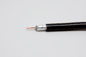
The Anatomy of a Video Cable with a Single Strand of Wire
There are five main components, made of various types of materials, of a typical single wire video cable. The outside of the cable is known as the outer jacket and protects everything inside of the cable. The shielding helps prevent interference from contacting the conductor and creating noise in the signal. It also works in reverse, helping to limit noise from the conductor from spreading beyond the cable. Depending on the quality of the cable, there can be multiple layers of shielding, such as rubber or foil sheaths. The dielectric protects the video signal and insulates the conductor. The conductor is the wire or wires that carry the video signal. The connector is the interface that allows you to plug a cable into the components.

Figure 5.2 Anatomy of a single strand of wire-based video cable
Source: Alex Oliszewski
Coax
There are a number of different cable connection types that all rely on the underlying analog coaxial (coax) cables. Coax cables are used throughout the world of audiovisual technology, most commonly associated with cable TV and home-based Internet connections. Coax is on a significant decline as hybrid digital cable types, such as HDMI, are taking over the market. In professional video production environments coax cables, such as those used with BNC connectors, still reign supreme. In the consumer market, today’s newest TVs still tend to include coaxial input types, such as RCA and Digital-RF antenna connections.
Different coax cables have different ohm ratings. The choice is normally between 75 ohm and 50 ohm types. 75 ohm is the most common and what you will likely find installed in your home. 50 ohm is used for extremely long runs of cable or for particularly high-resolution video signals. As a rule of thumb, when working at distances above 100′ it is recommended to use 50 ohm coax.
BNC
Standing for Bayonet Neill-Concelman, BNC is commonly referred to as a cable type, but is actually more properly understood as a connection type for coaxial cables. There are adapters available that allow conversion between RCA, BNC, and other coax-based connectors. In video applications, BNC connectors are most commonly made to match either 50 ohm or 75 ohm coax cables.
BNCs are a workhorse of the professional video world because they are shielded and tough. The 50 ohm types can be used over long runs of 200′. Video transfer interfaces, such as SDI and HD-SDI video formats, rely on them. When working with high-grade video equipment that uses coax cables with BNC connectors, such as SDI video interfaces, confirm with the equipment manufacturers if 75 or 50 ohm cables are needed.

Figure 5.4 Male and female BNC connectors on a coax type cable
Source: Alex Oliszewski
RCA
RCA cables are used for transferring analog composite video and stereo audio signals. The most common cables feature yellow (video), and white and red (stereo audio) connectors. The color coding of RCA cables is for the ease of installation and represents the only physical difference between the cables. A white cable can send a video signal just as well as a red or yellow one. RCA gained popularity first as an audio cable format for record players, which earned them the nickname “phono,” short for phonograph connections. This video cable typically carries standard 480i NTSC or 576i PAL resolution signals. In the theatre when working near lighting equipment and cables, unless you are using a well-shielded RCA cable, expect issues when pushing 50′–100′ runs.
RCA ports on displays and computers are being phased out in newer equipment. We still run across them, though, and find that it is good to have a few around when you want to use an older live video camera, VHS (Video Home System) player, DVD player, or video mixer.
There are also some video components that can serialize the transmission of color data over multiple RCA connections. This type of connection is often referred to as a component video connection. Component video cables split the video signal into three or more separate channels and allow for a larger overall color space, thus providing better overall video quality at larger resolutions than single RCA cables.

S-Video or Y/C
Standing for separate video and using a four-pin connector, S-video cables are also referred to as Y/C cables. They are a legacy format and represent one of the historical first steps in upgrading image quality from RCA-type video cables. While they allow a higher quality of video than typical RCA composite video signals, the noticeable increase in image quality is modest. They can be used to send 480i and 576i resolution video signals.
S-video cables are uncommon now. If you find yourself working with older video equipment you may still run across a need for this cable type. In our experience working in the theatre, they should not be considered for lengths over 30′.

Figure 5.6
Male and female S-video connectors
Source: Alex Oliszewski
VGA

Figure 5.7
Chart of VGA names and corresponding resolutions
Source: Alex Oliszewski
Though other standards are rising, the trusty VGA connection and its associated cable are still ubiquitous in conference rooms and lecture halls. However, it is definitely on its way out the door. This standard uses an analog-based signal and so you may find that it sometimes fails at providing pixel-perfect transmissions of content and causes other losses in quality to the image data. These can lead to color shifts and problems when trying to map or blend projectors to pixel-perfect precision. VGA is able to support a wide range of resolutions and frame rates, while allowing for relatively long runs and cable lengths. If you try to use a VGA connection of over 100′ you may find the need to reduce the resolution of the signal in order to maintain image quality, unless you use some sort of signal booster. If budget allows, avoid using VGA.

DVI
DVI (Digital Visual Interface) was the standard and first major player in consumer-grade digital video transmission, though some versions include support for analog signals for older monitor types still being used when it was first introduced. DVI comes in several varieties, which are used for different purposes and needs. DVI Single Link typically supports a maximum resolution of 1920x1200 and Dual Link 2560x1600, but this ultimately depends on the equipment you are using it with. There are three types of DVI connectors: DVI-A (Analog), DVI-D (digital), and DVI-I (integrated digital and analog).
HDMI and DisplayPort have pretty much replaced DVI at this point. DVI has a limited cable run of less than 50′ without a signal booster in line. We have found that the pins on these cables are susceptible to damage, as are the connectors. One beauty of DVI is that the connectors often include screw heads to connect to ports. As much as they hurt your fingers screwing them in, once they are connected they usually stay that way.

Figure 5.9
Chart of DVI names and corresponding resolutions
Source: Alex Oliszewski
HDMI
HDMI (High-Definition Multimedia Interface) represents a significant evolution in the utility of video cables. Unlike its ancestors, HDMI cables accommodate audio, 5-volt power transfer, and an ever-growing number of ancillary signal types commonly associated with video.
Like DVI, HDMI also comes in multiple versions. While the cables themselves have so far been backwards-compatible, you should ensure that the cables you have match the version of equipment you are using.
50′ is considered the longest length that HDMI is reliable. Use signal boosters or HDMI to Cat 6 converters for longer distances. Long cables are especially vulnerable to damage, even with gentle handling, and we recommend you have at least two backup cables ready to go at any given time when working with long runs.
Similar to USB, there is more than one type of connector used by HDMI cables. Small devices can utilize Mini or Micro HDMI connections. These are often found on cameras, such as the currently popular GoPro. The types pictured in Figure 5.10 represent the most common. We anticipate that some version of HDMI will continue as a video standard into the near future.


Figure 5.11
Male and female HDMI connectors and ports
Source: Alex Oliszewski
DisplayPort
DisplayPort is a companion cable to HDMI that is intended specifically for connecting computers and monitors. With an adaptor, you are able to convert a cable between HDMI and DisplayPort. Not all the functionality of an HDMI cable is replicated when being converted between port types as audio signals are typically dealt with differently by the equipment that relies on them. Like HDMI it also has a smaller version, called Mini-DisplayPort.
SDI
SDI cables rely on BNC-type connectors and coaxial cable types. Because of their frequent use with SDI video interfaces, BNC-type coaxial cables are sometimes also referred to as SDI cables.
As implied by its name, various groupings of SDI cables are used depending on the specific standard and features demanded by the equipment in use. Some devices with limited space have a special connector that breaks out into multiple BNC cables to carry the SDI signal.
There are eight types of SDI: SD, ED, and HD-SDI as well as Dual Link, 3G, 6G, 12G, and 24G-SDI. The three primary types of SDI that we have encountered working in theatre settings are SD-SDI, HD-SDI, and Dual Link-SDI. SD-SDI supports 480i, HD-SDI supports 720p and 1080i, and Dual Link HD-SDI supports 1080p60.
HD-SDI is prized not only for its quality but also for the range of additional data streams that can be incorporated with it. These include, but are not limited to, multichannel audio, the use of different color spaces, and timecode data.
The maximum range for an SDI-type signal cable depends on the specifications provided by an individual technology variant or manufacturer, but cable lengths of up to 250′ are normally considered reliable. Though expensive, we recommend the use of a fiber optic video interface to extend SDI over distances longer than 200′.

Figure 5.12
Male and female DisplayPort connectors
Source: Alex Oliszewski

Fiber Optic
Fiber optic cables are prized at the highest ends of the profession, both in live production and broadcast environments. When Cat 6–type video converters are proving unreliable in the theatre, or the environment has known interference issues, use fiber optic cables and interfaces. One of the standout features of fiber optic systems is that they are not susceptible to the interference suffered by metal cables. Even low-end fiber optic converters often claim ranges measured in miles and should transmit a strong signal even in a demanding theatrical environment. Strands of fiber optic cables are commonly sold in lengths exceeding 1,000′.
Unless your equipment includes native fiber optic connections, the signal needs to be converted to the types of connectors on the media servers and digital displays. There are SDI, HDMI, DVI, and other types of video interface conversion systems available. Depending on the type of video signal interface being converted, you may need to use a specific type of fiber optic cable that corresponds to the kind of conversion interface being used. Like SDI, fiber optic video cables are sometimes used in groups, allowing for different streams of data to be spread across different cables. The most common fiber optic cable you are likely to come across, which is not normally relevant to digital media design, is the TOSLINK-style fiber optic audio cable popular in high-end sound systems.

Figure 5.14
Male and female fiber optic/TOSLINK
Source: Alex Oliszewski
Thunderbolt
Thunderbolt (versions 1–3) is a video interface cable type developed by Apple for its line of computers. Like other types of multi-data video cables, Thunderbolt can transmit video signals along with other types of data. This cable is normally used as a high-speed data cable that allows port replication (allowing for the continued use of peripherals that rely on a different plug type) on docking stations or as a video display output.
Thunderbolt is prized because it provides access to the PCI Express bus on the computer’s motherboard, which allows for high-speed data transmission rates. If you use an Apple laptop, external hard drives, video capture cards, or other peripherals, this is typically the fastest connection type available. Thunderbolt 2 and 3 are fast enough to interface with devices that send and receive high-quality video signals, such as 4k and SDI, and provide access to video signals with low compression rates.
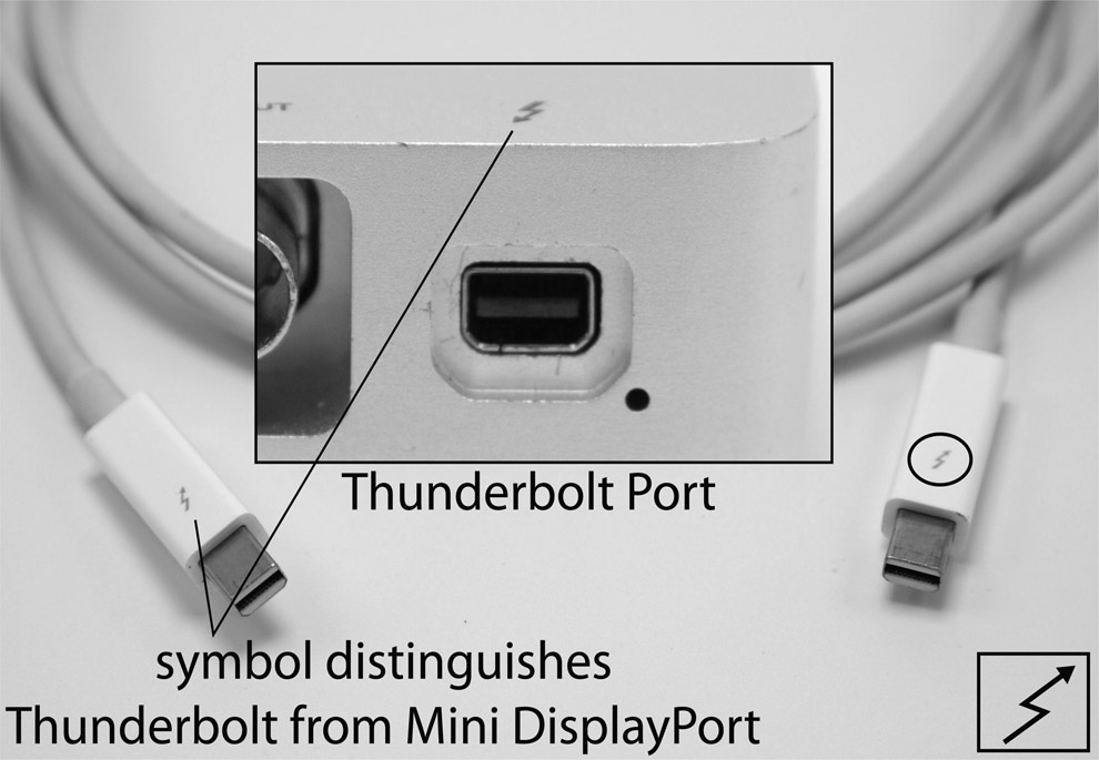
Figure 5.15
Male and female thunderbolt
Source: Alex Oliszewski
USB
USB is a common computer data cable that can also transmit power. Many web-based cameras connect using USB. Standard varieties are 1.0, 2.0, 3.0, and USB Type-C. The larger the number, the faster the cable. USB Type-C is currently the newest and fastest, providing up to 100 watts of power, which allows for more compact and powerful devices to be used with a single cable. USB 2.0 is just fast enough to provide decent-quality, if heavily compressed, video streams; however, we recommend no longer investing in any equipment that is not at least USB 3.0 or Type-C.
USB cables are not meant for long runs, and while 50′ and 75′ extenders exist, we have had mixed results in using them with anything but the simplest of USB-enabled devices, such as mice or keyboards. If you need to extend a USB-based camera, such as a Kinect, choose an extender that has an active (powered) signal booster.
FireWire
FireWire is now mostly a legacy connection type that came in two primary varieties, FireWire 400 and FireWire 800. The numbers refer to their bandwidths, with 800 being the faster of the two. Now usurped by USB 3.0, which is four times faster than FireWire 800, this standard has been abandoned in new equipment. FireWire cables are typically not reliable on runs of greater than 15′.
In digital media design, they were (are, in some cases) primarily used to transfer live video from digital camcorders and IR cameras. They were also commonly used for fast file transfers between external HDDs.
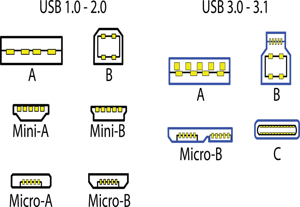
Figure 5.16
Chart of USB video cables
Source: Alex Oliszewski adapted from Darx, Damian Yerrick and Bruno Duyé

Figure 5.17
FireWire 400 and 800 cables
Source: Alex Oliszewski
Cat 5 and Cat 6 Ethernet Cable
![]() For More Info 5.1 Description of Cat 5/6 Cables
For More Info 5.1 Description of Cat 5/6 Cables
See “Cat 5/6 Ethernet Cables” in Chapter 5.
Cat 5/6 is easily used for video signal runs of up to 320′. It is an affordable cable for long runs, and there are a number of video adapters that allow you to convert to HDMI, DVI, VGA, and other video signal types over Cat 5/6 cables. Because of the high levels of interference common in theatre environments, invest in Ethernet cables that are well shielded regardless of their category.

When driving multiple projectors and their networked media servers over the hundreds of feet demanded in theatre installations, Cat 5/6 cables and signal converters are a good solution. Cat 5/6 can be purchased by the spool, allowing you to make custom lengths. This requires you know or learn how to attach and test the phone jack–like plugs on either end of a custom-built cable.
Video Signal Distribution Hardware
EDID Managers, Video Amplifiers, Replicators, Extenders, Repeaters, Splitters, and Distribution
Within the industry, you may hear a single piece of equipment referred to as a video amplifier, replicator, extender, repeater, DA (distribution amplifier), VDA (video distribution amplifier), EDID manager, or distributor. More or less these terms are used interchangeably, but there are differences between them depending on the manufacturer. With this class of hardware, you achieve three main goals: EDID management, amplifying a video signal, and distributing the signal to multiple displays.
Extended Display Identification Data (EDID) is a data structure, which conforms to the VESA (Video Electronics Standards Association) protocol, and allows computers to recognize the resolution of attached displays. EDID management is often necessary when connecting multiple display resolutions and/or when connecting displays over long runs. These devices allow you to discretely set and lock the resolution and order of each connected display from a media server. Not all hardware includes EDID management so take particular note if the system needs this feature.
Amplifying a video signal is needed on long cable runs. For instance, on a 200′ run of VGA cable, you may need to run two 100′ cables. Add a video amplifier in the middle to ensure the signal remains usable.
In addition to amplifying a video signal, you may also wish to distribute it to multiple sources. There are situations where you have more displays than the media server supports. In this case, the distribution hardware device accepts a single input signal, boosts the amplitude, and then sends it to multiple outputs without any degradation. The capacity of the hardware is determined by an internal processor. These units are either passive or active. Check the specifications before purchasing or renting to ensure that the hardware meets your specific needs. If you are using displays with multiple resolutions EDID management features are essential.
Replicating outputs is the same as mirroring, allowing you to place the same image on multiple displays. Depending on the device you choose you have to make detailed choices about the arrangement and size of display outputs.
Currently, the two most used video display replicators/extenders we have seen used in theatre applications are Datapath’s Video Controllers and Matrox’s Triple Head products.
Datapath
The Datapath is a professional-grade device that supports custom configuration through the included software. The software is PC-only, so you need to program and set up the hardware on a PC. Once configured, the Datapath works on Mac or PC video outputs. The software has a bit of a learning curve, but once you figure it out, it is pretty straightforward. There are four- and eight-output options. You can purchase as either a stand-alone unit or a rack mount. Since these are professional units, you can expect rock-solid performance.
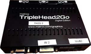
Matrox Triple Head
The Matrox Triple Head is a more affordable and consumer-focused version of the Datapath. It has custom software to configure the displays and is available for both Mac and PC. The Triple Head has either two or three output versions. In our experience the Triple Heads are less robust than Datapaths, but they also cost far less.

Figure 5.19
Front and back view of a Datapath × 4 display controller
Source: Daniel Fine
Video Scalers
A video scaler allows for the conversion of a video signal’s resolution and/or interlacing method, such as upscaling WXGA 1280x800p to 1080i. For a scalar to alter the resolution of an image it must interpret information to create new pixels. It does this by sampling the incoming video stream’s pixels and then effectively spreads or compresses that same amount of information across the needed raster. Scalers use different methods to ensure the final result looks as good as possible. Read reviews on scalers before purchase, as we have seen quite varied results in quality between models.
Removing image information to reduce resolutions is called downscaling. This is a simpler process than upscaling, as removing data is easier then inferring new data.
Video scalers are particularly useful when designing a system with interlaced and deinterlaced video equipment. They are an affordable way of maintaining compatibility between legacy systems and newer equipment.
In the theatre, scalers are used to send a single video signal, such as HDMI or VGA, to multiple displays with different signal formats and/or resolutions. Using a video scaler to convert or duplicate a video signal coming from the media server can reduce latency, which is desirable. Some scalers allow for EDID management as well, so you can more easily convert a signal type and lock it down.
Video Mixers
A video mixer is a device that receives multiple inputs and allows for their simultaneous display and compositing. They are essential for live broadcast of sporting and awards events. While media servers are often capable of duplicating the functionality of video mixers, this can introduce unwanted latency. A computer’s CPU or GPU will likely never match the low latency of hardware-based video mixers.

Figure 5.21
Back panel and top view of a Roland V-4EX video mixer
Source: Alex Oliszewski
Most video mixers have built-in keying capabilities, with higher-end models also supporting alpha channels. Just as they do for live television, video mixers in the theatre allow designers to easily combine live and prerecorded video content at the lowest possible latencies.
Video Cable Adapters and Signal Converters
Video cable adapters change the physical connections of cables and devices from one type to another. Video signal converters actually modify the type of video signal from one to another. Adapters and converters are available for almost every type of video signal and often come in some type of cable form. Yet, not all adapters are created equal. If you find an adapter that is much cheaper than all the rest don’t assume it will actually work. A converter is always needed when converting between analog and digital devices.
Wireless Video
When cables are not an option but video must be delivered from point A to point B, wireless transmission is an option. Contemporary theatres can prove to be complicated wireless environments to work in. Audio designers in particular tend to use wireless microphones and front-of-house teams often communicate using high-powered walkie-talkie systems. Audience members introduce hundreds of Bluetooth, Wi-Fi, and cell radio interferences to performance venues in a way that is almost impossible to simulate before opening night, and there is significant potential for poor performance with the lower end of wireless video transmitters currently available on the market.
There are a large number of wireless transmitter types, so you should be able to find one that meets any common video transmission standard from RCA all the way up to HD-SDI. These types of systems can get quite pricey if you need to work at high resolutions. Some include battery-powered belt pack–type transmitters that are meant to be powered directly off of a professional video camera’s power pack or otherwise enable it to be worn by a mobile video camera operator who requires freedom of movement. Other versions of this technology rely on transmitters and base stations that require a dedicated wall plug for power.

Still other types require a wire running from the camera to the transmitter, and the transmitter must be stationed within clear sight lines to the receiver, as well as somewhere near a power supply.
RF Modulator
Occasionally you may use a display that has only coax inputs, meant to receive RF video signals. In order to convert this signal type to VGA or another video signal type, a special RF modulator is needed.
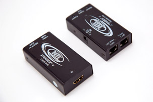
Cat 5/6 Extenders
Cat 5 and Cat 6 video conversion devices transmit a video signal over a longer distance compared to the native run lengths of a particular cable, such as HDMI or VGA. On the input side, these devices increase the native voltages of the incoming video signal so that it can travel further distances made possible by Ethernet cables. On the other end of the cable, the Cat 6 extender then reduces the voltages back to the original specifications. The converters need to be powered and attached to each end of the cable.

Figure 5.23
Top row: coax to RCA modulator. Bottom two rows: multiple views of a VGA to RCA/S-video modulator.
Source: Daniel Fine
Not all extenders are made equally. Read reviews and don’t be swayed by the cheap ones, because they may not work as promised over long runs in a theatre setting. Regardless of build quality, slight changes in a signal’s final voltage can occur. These devices might cause negligible degradation of image quality. They should include some form of gain control that allows for you to tune its signal output. We regularly use and recommend these kinds of extenders to those needing to balance robustness and affordability of long cable runs. Check the specifications for EDID pass-through features.
Analog-to-Digital Converters (ADC) and Digital-to-Analog Converters (DAC)
ADC and DAC devices are used to translate analog signals and digital signals back and forth. They are heavily used by sound designers when dealing with microphones and digital audio systems. Digital media designers who are working with analog cameras use them to convert the analog video signal for capture in a media server. Conversely, you may need to convert an HDMI or other digital signal for input into a system that accepts only analog signals, such as component video (YUV/S-Video) or RCA.
Media Servers
A media server is simply anything that plays back media. In the simplest form, a media server can be a CD, DVD, or VHS player. Modern media servers make the job of playing back media files (video, images, sound) for a show reliable and repeatable in terms of being able to cue the video content with the live performance while quickly changing the way that content is played back.
Theatrical media servers typically allow for control of the content, such as speed, looping, and changes in intensity, saturation, and contrast, as well as the ability to decide where a particular video clip starts and stops playing. Most media servers are able to send and receive different network messages in order to communicate with other systems and equipment. Many media servers have built-in mapping and blending tools. Features are not standard across all media servers. You should know what the server you are using can and cannot do before heading into any professional setting.
Today’s media servers are very sophisticated. There are two main categories of theatrical media server: software – based and turnkey solutions. Software-based solutions allow you to operate on any computer that meets the minimum requirements of the software. This allows for more flexibility and custom configurability, while also representing the most affordable option. Turnkey solutions include software and hardware (computer). For this reason, they are typically regarded as more robust. They are also more expensive, often by many thousands of dollars.
![]() Aside 5.1 Building Your Own Media Server
Aside 5.1 Building Your Own Media Server
If you want to build your own computer to act as a media server or you need to spec the hardware on an existing computer, you need to understand what the components of a computer are and why they matter for media servers.
Graphic Cards
What Is It/What Does It Do?
The graphics card or GPU (graphics processing unit) in a computer comes in many different flavors. Today you’re likely to see computers with integrated graphics cards, discrete graphics cards, and sometimes even a combination of those two. Integrated graphics cards are usually found on laptops and in this case the graphics processing unit is tied into the motherboard of the computer. A mother-board is the central circuit board that components are attached to in your computer.
Integrated cards are typically much more power-efficient, and reduce the presence of another component in your computer. The primary drawback of integrated cards is that they are typically less powerful than discrete cards—in terms of both processing power and memory.
Discrete cards are stand-alone components that are attached to the motherboard in your computer. These come in lots of different shapes and sizes, affording the user many different configurations. While these cards offer the best performance, that processing power typically comes at the cost of power efficiency and space.
Configurations offering a combination of both types are common in higher-end laptops focused on the gaming market. Computers with both an integrated and discrete GPU are a common solution for graphics power and extended battery life. Many modern operating systems allow for smart switching between integrated and discrete cards—the idea here is to create a computing experience that has power when you need it, and power efficiency for most other computing tasks.
Like its name suggests, the GPU is used for rendering images on your computer—everything from rendering web pages to rendering the fantastical worlds of modern games, and even making for speedier processes in video and image editing applications. Unlike CPUs (central processing units) that tend to handle processes in serial (one operation after another), GPUs handle processes in parallel (many operations all at the same time). Due to their parallel computing nature, GPUs tend to be much faster at many computation processes—though they’re not well suited for all problems.
GPUs have both their own processors and their own memory—both factors matter in GPU design, though when building a machine, you might have to choose between faster performance or more memory. It’s important to note that the GPU’s memory, VRAM (video random-access memory), is different than your computer’s primary memory, RAM (random-access memory).
How Do I Pick the Right One?
If you’re building a media server, chances are you’ll want a discrete GPU. While integrated GPUs may seem like a good idea on paper, for many high-end playback situations you often want as much computation power as you can manage, and not to be stranded with an integrated graphics solution. You’re also likely to want more VRAM than an integrated card will have.
Discrete cards come in a huge number of varieties, so choosing the right card can be a daunting process. There are a number of things to keep in mind:
More GPUs don’t always mean better performance. While many modern games support multiple GPU configurations, programming environments and turnkey media server software packages might not. It’s never safe to assume that more cards mean better performance. Instead it’s important to do your research and make sure that your application or development pipeline will benefit from multiple cards.
Not all applications and development environments are optimized to benefit from using a GPU. A great number of applications and pipelines benefit tremendously from using a powerful GPU, but not all of them. Some processes are inherently bound to the CPU and see no significant gains from a faster GPU. While many live rendering pipelines benefit from additional graphics processing power, typical movie decoding may not (this is largely dependent on the type of codec you’re using for your video). Before choosing a card, it’s important to first think about what your server needs to be able to do and the type of computation work it will primarily be used for.
Card vendors shouldn’t matter, but sometimes they do. While searching for a bargain GPU is a tempting endeavor, it’s also important to realize that not all applications are optimized for all graphics cards. That is to say that in some cases applications and development environments may be optimized for better performance on a single vendor’s cards. Both NVIDIA and AMD make powerful video cards, but it’s important to make sure that the applications you plan on using will benefit from the card you purchase.
Some general ideas worth considering:
- The newest technology is always the most expensive. While it might be tempting to get the newest card on the market, it’s likely to be out of date in just a few short months.
- VRAM is hugely important for modern rendering environments. When working with large textures, high-density displays, or large numbers of displays you’ll want to make sure your GPU has plenty of memory to accommodate those needs.
- Professional cards aren’t always the best solution, but sometimes they are. It might be easy to shrug off the idea of a $5,000 video card, but it might be the right solution. Then again, the consumer-level card that’s just a little slower might be more than enough. High-end cards tend to support important features like frame-lock (keeping multiple video cards in sync) and have better multi-display support.
- Choosing the right video card is hard; read lots of reviews, and ask your colleagues about how to determine the right piece of hardware.
HDD/SSD
What Is It/What Does It Do?
Hard disk drives (HDD) come in many varieties and are an essential part of your server build. Drive space is especially important for video playback as it can be a bottleneck in your pipeline. Your hard drive not only holds files that allow various applications on your computer to run but also is where you store your video files. These days’ disk drives come in three primary varieties: platter drives, solid-state drives, and hybrid drives.
Platter drives are the oldest technology of the three varieties, have the largest capacity, and tend to be the most cost-efficient. Platter drives are just that— they’re composed of several platters or disks that are stacked together in a single housing. These platters spin at several thousand revolutions per second and the information is read off and written to them with a small head that moves across the surface of the platter. Platter drives are rated based on, among other properties, their rotation speed. You’ll often find platter drive speeds described as 5400 rpm or 7200 rpm.
Solid-state drives (SSD) are a type of memory technology that involves no moving parts. Similar in principle to a USB memory stick, an SSD uses electrical current to change the state of “flash” memory. This type of memory holds its state even without power, ensuring that you don’t lose any information even when your computer is turned off. While SSD prices continue to come down, this is typically a more expensive form of memory than platter drives. SSDs may be more expensive, but unlike platter drives, SSDs have no moving parts and consequently are able to access files at a much faster rate.
Hybrid drives are a combination of platter and SSD technologies. These types of drives typically have a portion of the drive that is flash-based, while another section of the drive is platter-based. This is largely hidden from the user, and in some applications, the management of the memory is also obfuscated from user—the principle here being that the operating system should work in tandem with the drive to store frequently accessed contents in the flash memory portion, while infrequently accessed information is stored on the platters. While this is certainly a powerful technology for many uses, it’s not one that’s especially advantageous for building a media server.
How Do I Pick the Right One?
By and large you probably want to use SSDs to house your media files. This is especially true if you’re dealing with large assets, 4k video and above, or playing back multiple files simultaneously. Fast read speeds are essential to good playback performance and currently SSDs are a strong choice. That said, you might well decide to put multiple drives in your server.
For example, you might want a platter drive to house your operating system and working files while you’re animating, and a smaller SSD for finished assets that you use for playback. Alternatively, you might decide that you want to work with just SSDs on the server, and rely on USB 3.0 or above, Thunderbolt 2 or above, or eSATA externals for working files.
Regardless, it’s worth remembering that more space is better than less when dealing with hard drives. It’s easy to accumulate files quickly, and when you’re deciding on the amount of space for your assets, it’s good to err on the side of larger rather than smaller. If you can afford it, 1 terabyte of space is a good place to start for your assets—if at all possible, you shouldn’t give yourself less than 500 GB. That may seem like a lot now, but drive space can disappear quickly if you’re working on complex projects.
Processor Speed
What Is It/What Does It Do?
The central processing unit (CPU) does the lion’s share of computing tasks on most computers. The major defining characteristics of a CPU are its clock speed and number of cores. A speedy CPU will help ensure your applications feel fast and responsive. This is also the primary bottleneck for many computing challenges.
Clock speed is a measure of how many cycles per second a microprocessor is capable of when executing instructions. For example, 1 GHz represents one billion cycles per second. This measure is helpful in getting a sense of the performance speed you’re likely to see from a processor. Many other factors matter, but generally speaking, a faster CPU will usually equate to faster performance provided that you have sufficient system resources.
The number of cores on a CPU refers to the internal architecture of the microprocessor. We can reductively think about multi-core CPUs as having multiple processors. It’s important to remember that CPUs largely perform operations in sequence—A then B then C then D and so on. Sometimes when your computer becomes unresponsive it’s precisely because it is busy working through the computation associated with a previous operation. Multiple cores are a step in helping to address this problem as they allow your computer to multitask. It’s not uncommon to see terms like multi-core or hyper-threading used to describe this process. In brief, we can think of this as a means of allowing your computer to do multiple operations at the same time by giving different processes a discrete environment to operate in. Your virus scanner can run in the background without interrupting your work editing images or video. When you’re rendering a complex scene in a 3D authoring program your computer is able to work on multiple parts of the computation associated with creating the final image. This, of course, has limits—some operations need to be performed in sequence, while others can be performed out of sequence.
How Do I Pick the Right One?
Faster isn’t always better, and neither is more—which is to say that some applications benefit from multiplecore CPUs while others might ignore multiple cores and will benefit only from a faster clock. How do you choose then? Generally speaking, most modern applications don’t see huge benefits in performance past six cores. Applications will, on the other hand, almost always benefit from a faster clock.
You will, however, probably have to choose between more cores and a faster clock speed—so how do you choose? In terms of video playback most decoding happens on the CPU (with the exception of some specialized codecs). Some applications and development environments support multi-threaded video playback; if this is your case and you’re dealing with playing lots of simultaneous videos then you might see better performance from choosing a processor with more cores rather than a faster clock. If, on the other hand, you’re working in real-time 3D environments with complex changes in your scene and changes to the geometry you’re likely to see more direct benefits from a faster clock.
RAM
What Is It/What Does It Do?
Random-access memory (RAM) is used by your computer for all manner of operations. We might, as a metaphor, think about RAM as being similar to counter space or desk space. When you’re working on a project it’s often helpful to spread your work on a big table or counter—it lets you see everything at once, and find anything you need very quickly. RAM is used by your computer to put lots of information into a place that’s easily and quickly accessible. One caveat about RAM is that it requires power to maintain persistent memory—which is to say that when you turn your computer off, whatever is in RAM is lost. Every application on your computer uses RAM, and when you use all of your available RAM the operating system on your computer will try various techniques to keep working, but essentially it will just slow down. RAM is an essential part of your server build and in some cases adding more RAM can have a more powerful impact than a faster processor or faster GPU.
How Do I Pick the Right One?
These days RAM is typically described in terms of gigabytes (GB). If you have a 32-bit operating system you won’t be able to use more than 4 GB of RAM. Luckily for you, that’s probably not the case. Just about every modern operating system is now 64-bit. Some applications, however, are not. An application that’s only 32-bit will be able to use only 4 GB of your machine’s RAM. If you’re building applications, or using off-the-shelf software it’s worth noting if the application is 32- or 64-bit.
Okay, so how much RAM do you want? As much as you can afford/fit in your machine. It’s a good idea to install at least 8 GB of RAM for most modern computing. Generally speaking, you will probably be happier with 16 or 32 GB of RAM. You’ll probably see RAM described as something like: 16 GB (2x8) or 16 GB (4x4). Here, 16 describes the total amount of RAM. The numbers in parentheses describe how that memory is spread across the hardware. 2x8 means that you have two 8 GB sticks of RAM. 4x4 means that you have four 4 GB sticks of RAM. This is an important detail to consider. Generally, you want fewer, denser sticks of memory. Why? A motherboard has a limited number of slots for RAM. By using fewer slots initially you end up leaving yourself room to expand later on.
PCI Slot/Expansion
What Is It/What Does It Do?
A Peripheral Component Interconnect slot (PCI) is a standard expansion slot on a motherboard. Many additional computer components can be attached with PCI or PCIe (Peripheral Component Interconnect—Express). Modern motherboards typically have both PCI and PCIe slots. PCIe slots are used for components that need fast, high-bandwidth access to your motherboard. Adding an additional network adapter to your computer—that’s probably PCI; adding a capture card for multiple 4k inputs—that’s probably PCIe.
How Do I Pick the Right One?
If you’re building a server yourself, it’s worth thinking carefully about what other components you want/need in your server. Do you need a sound card, or an additional network card? What about a capture car for live video, or an uncommon interface element, like fiber? You’ll want to make sure you purchase a motherboard that has enough space to accommodate your other components and has some free space to attach additional internal components to expand your machine’s capabilities.
If you’re buying a computer from a manufacturer or a vendor that configures machines then you’ll likely want to think about any additional needs your server might have now and in the future, and plan to have enough space to attach these other components.
Turnkey media servers are PC-based due to the customization of hardware. Software-based servers may be either multi-platform, Mac-only, or PC-only, depending on the developer. Some multi-platform servers like Isadora have specific features per platform. For instance, on the Mac version, Isadora has a number of features built upon Quartz Composer. These features do not exist on the PC version of Isadora, since Quartz is Mac-only. The underlying methods of graphics handling are different on PC and Mac computers. Expect to see variations in performance across operating system platforms.
There are a wide range of media servers that each focus on a different segment of the performing arts and live events industries. Media servers have different forms of cueing logic. The four main types of cueing logic used in media servers are as follows:
- Timeline-based servers have a playhead that moves across multiple layers of video similar to the graphical user interface of a nonlinear video editing software. Typically, timeline-based servers work in a similar logic to editing software in terms of layering, compositing, and sequential playback.
- Layer/cue stack-based servers allow you to program content for playback through a spreadsheet-like system where you can move between cues without a playhead moving in time.
- Node-based servers have a variety of different methods to play back cues. Isadora is currently the only type of node-based server we are aware of that is specifically created for playback of cues as understood in the theatrical context. All other node-based servers we are familiar with, such as TouchDesigner and MAX, require you to program a custom method and interface for playing theatrical-type cues.
- VJ-based servers typically do not have cue systems designed for theatrical situations; however, we have seen them used to great effect by designers where idiosyncratic playback of content is desired. These types of servers typically offer the ability to quickly composite, add effects, and adapt content playback, while integrating with other software applications through features such as Syphon/Wyphon.


Most media servers allow you to hand over the operation for the run of a show to a relatively unskilled board operator. If programmed correctly, the operator is able to run the show with no additional programming and minimal control. They can use a single go button to execute a cue and should have a method for jumping between cues when one is missed or needs to be skipped for some reason during an individual performance.
For More Info 5.2
See “Types of Media Servers” in Chapter 5.
It is common for the sound department to play audio without the need to route through the media server. There are times when the audio and video need to be perfectly synced, such as when a prerecorded video character is delivering lines, so often these soundtracks are played along with the video in the media server to avoid latency. In this case, the media server needs an audio line out to the sound department. This allows the audio designer to control levels and ensure quality and continuity in their sound design. Be aware of the capabilities of the media server when it comes to playing audio and work directly with the sound designer to ensure system integration before technical rehearsals. Latency can still be an issue, so test that the two systems are in sync.
As with any technology, media servers are becoming more powerful and affordable every day. The only thing for certain is that tomorrow everything will be different. The career of a digital media designer is one of constant learning and adaptation to new technologies and buttons.
Types of Media Servers
Timeline-Based Media Servers
Timeline-based media servers use the same types of visual metaphors for setting and manipulating content as nonlinear editing (NLE) packages, like Final Cut Pro, Avid, Premiere, and so forth. On these systems you align video, define fades, set in and out points, place still images, and control various types of triggerable equipment all via a timeline, as you would in a NLE editor. Timeline-based media servers offer a familiar interface metaphor for video editors. Their learning curve is normally quite shallow for new designers and programmers already familiar with video editing. Watchout is the theatrical standard of this kind of media server.

Figure 5.26
Screen capture of Watchout media server interface
Source: Alex Oliszewski
Timeline-based servers typically support the layering of video and basic compositing effects, such as keying, color correction, cropping, and image blending. If the computer is properly configured and equipped, timeline-based servers also allow the mixing of live video signals and digital files. The ability to keep content in separate layers that are edited in place to the live action can offer significant time savings and for a skilled programmer enables quick responses to a director’s notes.
Layer/Cue Stack-Based Media Servers
Layer/cue stack-based server interfaces act more or less like spreadsheet cells where you can type in information. The server stores information and counts time while moving between settings and cells of what ultimately is a spreadsheet. Layer/cue stacks track the order of cues as well as applied effects and timings associated with them for playback.
The layer/cue stack has been the mainstay of digitized theatrical cueing devices and electronics since their first integration into theatre productions. Theatrical lighting boards and audio cuing systems have relied on the cue stack method for timing and cuing because it is a robust and logical way of dealing with automating dimmers, volumes, and other functions.
Because of the connection to existing methods of cuing audio and lighting, cue stack-based media servers integrate excellently into the theatrical cueing process. They typically are more robust in their support for audio playback and can often allow the consolidation of both audio and video content into a single server, such as QLab. This can reduce the cost of both the equipment and the number of operators needed to run the show.
Layer/cue stacks allow for basic real-time control of content, while also providing fast programming and well-designed playback interfaces.

Figure 5.27
Screen capture of QLab Media server interface from One Man Two Govners . Digital media design by Jeromy Hopgood.
Source: Jeromy Hopgood
Node-Based Media Servers
Node-based (sometimes called patch-based or flow-based) media servers use small building blocks, each with their own functionality, to build the logic and flow of data. These building blocks, or nodes, have inputs and outputs that link together to make a patch (sometimes called a graph). Node-based media servers can rightly be considered a type of programming language or environment in that they often do not come with a predetermined method of use, but instead provide libraries of possible functions that assemble into highly customizable configurations.
Since node-based environments often work closely with software libraries and other resources it is often quite possible to accomplish custom tasks by importing or developing additional functionality and libraries that integrate into the server. This means that if you are trying to use a new sensor or some uncommon piece of gear, node-based media servers are often the only type flexible enough to allow for integration without having to get support directly from the developer of the media server software. Other types of media servers have made great strides recently in integrating sensor-based interactions that are the hallmark of node-based media servers. However, they are still catching up when it comes to the flexibility and upgradability of node-based servers.
Aspects of node-based programming are included in some advanced media servers, such as Pandoras Box, and various content creation software packages, like After Effects. This provides an artist-friendly method of manipulating low-level computer behaviors normally addressed with text-based code.

Figure 5.28
Screen capture of Isadora server interface
Source: Alex Oliszewski
As patches become more complicated, they begin to take up a lot of screen real estate. We recommend using large external monitors when programming these kinds of media servers on a laptop. Patches can quickly become clunky and ungainly, making it difficult to figure out what is going on within the mess of wires and lines connecting everything. Organization and notation are crucial when needing to quickly look at a patch and understand what is happening.
Once you are facile in using this kind of media server the speed and ease with which you can program and affect content in a rehearsal are amazing, but getting to this point is not as easy as mastering other types of servers. If you use node-based servers other than Isadora it requires you to program a custom method and interface for cueing. This is not a trivial task when dealing with a large number of assets and the intensely limited amount of time available to programmers in rehearsals and tech.
VJ-Based Media Servers
VJ-based media servers are designed as more of a real-time instrument allowing artists to mix and composite premade content and live video cameras. Since they are designed for manipulation by an artist in real time during a performance, they do not typically have a cueing method for theatrical playback of prerecorded looks. This class of media server has advanced in recent years to include powerful video mapping capabilities. They easily route to and from interfaces, cameras, and other software packages for warping/mapping, like MapMapper. They are great tools to quickly manipulate video and allow for dynamic performances.
Common Media Server Features
Tip 5.2 Order of Turning On/Off Equipment
It is important to turn on and off the equipment in the proper order for everything to work correctly.

Figure 5.29 Screen capture of Resolume media server interface
Source: Alex Oliszewski
Order of turning on gear:
- Projectors/displays
- Media server
In order for the media server to properly recognize the displays they need to be powered on. If you don’t power on the displays first and then power on the media server, the computer may re-sequence the order of the displays. This could mean that you end up sending content to the wrong display. EDID management devices can help solve this, but it is still a good practice.
Order of turning off gear:
- Media server
- Projectors/displays
The media server should be powered down, with all of the displays still on. This way, the server remembers the proper sequence and routing of each display. Once the media server is off, power down all displays.
Built-In Mapping and Masking Features
Some media servers have the ability to warp/map content to specific surfaces and to use premade and custom masks. Generally, the most robust mapping and masking capabilities are found on turnkey media servers, but for most theatrical productions mapping features offered by Watchout, Isadora, and QLab are more than sufficient.
![]() For More Info 5.3 Warping/Blending, Projection Mapping, and Masks
For More Info 5.3 Warping/Blending, Projection Mapping, and Masks
See “Working with Projectors” in Chapter 5.
Max # of Inputs
This refers to the maximum number of individual video signal inputs a system is capable of directly ingesting.
Max # of Outputs
This refers to the maximum number of individual video channels the system is capable of directly outputting for display or further manipulation and distribution.
When dealing with software-only servers the chosen hardware is just as important as, if not more important than, the software’s capability. The fact that the software allows you to have x number of inputs/outputs does not mean the computer is capable of actually outputting that number at performance-grade quality. Computer hardware in turnkey servers is configured and optimized to work with the software and typically is limited in its feature set to ensure performance quality. On self-built systems, it is up to you to make sure that the system is configured properly for optimal playback.
Max # of Layers
Layers generally refer to the number of separate video or image files that can be played/placed concurrently within the same raster/display space. In this way designers are able to mix separate elements in real time and maintain flexibility in the timing and composition of how content is composited on the stage.
Max # of Simultaneous HD Videos
While some servers may have many layers, there is a cap as to the amount of HD movies that can play at any one given time without dropping frames.
Notable Supported Protocols
There are a number of networking protocols that a media server may be capable of interfacing with in order to communicate with other equipment.
![]() For More Info 5.4 Networking
For More Info 5.4 Networking
See “Networking” in Chapter 5.
![]() Tip 5.3 Updating/Upgrading Media Server
Tip 5.3 Updating/Upgrading Media Server
When is it a good time to upgrade software or hardware?
Upgrading usually comes with the need to update plug-ins and can take anywhere from twenty minutes to multiple days to complete. Give yourself extra time whenever upgrading the media server. Make sure to check that the new version of the software and hardware complies with all the related equipment and associated software you are using. Upgrading can have other dependencies, such as the need for the latest operating system or new video codecs installed. If you don’t have these readily available you can find yourself stuck in the middle of the process and lose important working time.
You don’t want to upgrade the software-only media server only to find it won’t run effectively on the computer after the install. Do your homework by reading all the technical specifications first.
Do not update the media server after beginning to program a show unless you are willing to start again from scratch. Things can go wrong and you don’t want to lose time to troubleshooting problems while you are in the midst of a project. Plan updates in-between shows.
This also is true for operating systems. Before upgrading the OS, make sure that the current media server software and hardware you are using work with the new OS.
Projectors
There are currently four main types of projectors (DLP, LCD, LCoS, and Laser) that are commonly used in theatrical productions. They share and differ in many of their specifications across types, makes, and models. This section covers the basics about projectors, the related gear associated with them, and the fundamental technical tasks involved with working with them in the theatre.
Projector Types
DLP
DLP (digital light processing) describes the image creation device used by these types of projectors that have small moving mirrors to either block projected light or reflect it so that it passes through the lens. These projectors have the advantage of achieving a better quality of video black, which produces better dark tones than LCD technologies. Typically, light passes through a single DLP chip, consisting of a sequence of spinning colored glass filters that produce the different colors (RGB) needed to reproduce an image. On some higher-end projectors there are three DLP chips, one for red, green, and blue.
When video is projected by a DLP projector, it may contain a shifting rainbow effect created by the red, blue, and green reflected from the projector’s spinning disk of dichroic filters. If you use live video in a production that catches sight of a DLP projection you may see the rainbow effect in that live video. You may see the rainbow effect when using a video camera to document the production. By changing the shutter speed and frame rate of the video camera capturing the projection you may alleviate this problem. We have heard anecdotal stories that there are even some people who can see this effect with their naked eye. Though rare, those who see it have found it quite annoying.

Figure 5.30
Shifting rainbow effect of a DLP projector as seen by a video camera
Source: Alex Oliszewski
LCD
LCD (liquid crystal display) describes the image creation device used in these projectors. LCD projectors represent the reason that video projection has become affordable and so widely adopted, by not only the theatre and performance community but also enthusiasts interested in building personal home cinemas. They provide sharp images, come in small sizes, and are often more affordable than other types of projectors.
This type of projection technology is similar to most LCD televisions. An image is created by allowing light to transmit to three liquid crystal panels. There is one panel for red, green, and blue. A light beam is split between the three colors and then recombined to create a full-color image.
The video black and dark tones created by LCD projectors tend to be brighter than those created by DLP projectors, offering less range in contrast than other newer projection technologies. These types of projectors are more susceptible to dust and other foreign bodies than DLP projectors and in turn tend to require more maintenance and cleaning during a performance run that lasts more than a few weeks.
LCoS
LCoS (liquid crystal on silicon) describes the image creation device used and is similar to that of LCD projectors. Instead of using a transmissive method, LCoS uses a reflective method of forming an image with an LCD panel. LCoS projectors tend to achieve better contrast ratios as well as darker video black and dark tones. However, along with LCD, these types of projectors are becoming rarer in favor of DLP and newer laser projectors.
Laser
Once known as LASER for “light amplification by stimulated emission of radiation” the term is no longer used as an acronym and simply referred to as laser. Unlike the other projector types listed here, laser describes not the image creation device but the light source. DLP, LCD, and LCoS imagers are still used in laser projectors. LCD-based laser projectors provide the sharpest and brightest images of any technology currently available, though they are relatively new and quite expensive to use at most theatrical scales.
LCoS-based laser projectors, unlike other projectors, have no specific set focal distance. This allows the projected image to be sharply focused over a wide range of distances. This is particularly desirable when a designer wants to project an image on a dimensional geometric surface, as is common in video mapping applications, or when images need to be projected on multiple surfaces that are placed at varying distances from upstage to downstage. Other advantages include:
- The ability to nearly instantly turn on/off since there are no lamps.
- Less fragility.
- Rated for a longer life than lamps.
- The ability to mount on the side, point straight up, or point straight down.
- Less maintenance.
- Enclosed lighting elements that do not require cleaning over the course of a long run.
Technical Specifications of Projectors
Lumens
Established by the American National Standards Institute (ANSI), the ANSI lumen is the standard calculation used to measure how bright a light source is. Lumens are the brightest at the center and drop off toward the edges. Projectors have different settings, such as eco, standard, gaming, and cinema, that affect the lumen output, as well as the color temperature and the lamp life.
Resolution and Aspect Ratio
Projectors have different native resolutions and aspect ratios. When possible, always use the native settings. Other resolutions and aspect ratios are simulated by adding black bars to either the top/bottom or sides of the image.
Contrast Ratio
The projector’s contrast ratio determines the level of black. A contrast ratio of 5,000:1 means that the white of an image is 5,000 times brighter than the black. The higher the contrast ratio is the more detail and the blacker the blacks are. Typically, the lowest contrast ratio you should work with is 3,000:1.
Inputs/Outputs
Projectors have a number of different input types, with VGA and HDMI being the most common. Some projectors are pass-through-capable, meaning there is a video signal out. This allows you to either directly monitor the projector’s output or duplicate it by passing the video signal onto another projector.
Fan/Air Flow/Filters
All lamp-based projectors have a fan to cool the lamp(s). To cool the lamps the fans circulate air by taking it in from one place on the projector and then blowing out the hot air via an output. The fans can be loud, which may be a problem depending on where they are installed. Try to avoid any fan noise over 60 db. There are disposable air filters over the air intake/output to protect any particulate matter from entering the inside of the projector. The filters need to be replaced regularly. Refer to the projector’s manual so you are familiar with maintenance needs and schedules.
Network Capable
Some projectors are capable of connecting to network, usually via Cat 5/6 or serial inputs. Many new models have browser-based interfaces to control them remotely over the network.
Sometimes when you have the same projector make and model that are positioned near each other, the remote controls both projectors, which may become a hassle when trying to make changes to a projector’s setting. You can avoid this by controlling them via the browser interface. An added bonus of controlling the projectors via a network is that you can access all of the projector’s settings, including power, right from the tech table. You should specify network cable runs in the system diagram and connect all projectors to the same local network that the media server or show control computer is connected to. Having a dedicated laptop or other computer to interface with the projectors is recommended.
Installation
Most projectors have a maximum tilt angle specified. Do not assume you can point a projector straight up or down or install it on its side. It is a very rare (and expensive) projector that allows you to do any of these installation methods, though it is a common feature of most laser projectors.
When installing projectors do not block the air intake/output. Leave at least one to two feet from the projector to other equipment or walls to allow for airflow. Without proper spacing, the heat that projectors discharge quickly builds up and may cause a projector’s internal sensors to trigger a shutdown. In a worst-case scenario, overheating can permanently damage a projector or cause visible distortions in its output. Refer to the projector’s manual for airflow warnings before building any baffles or boxes around them to control light leaks or fan noise.
Projector Lenses
Professional projectors have interchangeable lenses, while cheaper, more portable projectors usually have a built-in lens. Projector lenses are similar to camera lenses, but differ in the fact that they are meant to direct the light from the projector out onto a surface to produce an image, rather than directing the light from a subject into the camera’s sensors to capture an image. F-stop and focal length are the two main technical specifications that you should be aware of when choosing and working with projector lenses.
The f-stop, like in camera lenses, is a number that specifies apature, which controls how much light it allows to pass through it, aiding in the rendering of image contrast and brightness. The lower the f-stop number is, the more light it allows to pass through, which in turn affects the depth of field similar to how a camera is affected. However, this is less of an issue with projectors in typical installations where the focus is set and locked to a single plane. As a rule of thumb, get the lowest f-stop lenses you can to ensure the brightest images. Most advanced projectors and lenses actually change the f-stop on the fly with a dynamic aperture to insure the best contrast levels.
The focal length, usually specified in millimeter ranges (i.e., 50–75 mm), is used to determine the ratio between the final image size on the desired surface and the throw distance—the distance from the tip of the projector’s lens to the screen. Typically, manufacturers specify the f-stop over the entire focal length of a lens, so for a 50–75mm focal length you might have a f2.0–2.6 f-stop range.
Marketing standards for projector lenses are hardly standard and can get confusing with the different terms and methods used by various manufacturers. Some might detail throw ratio and focal length, while another lists zoom ratios and maximum and minimum distances. These describe essentially the same thing, but require slightly different methods of decoding. It can be tricky, so make sure you understand how the specific manufacturer is using the terms to determine the lensing that is right for your application.
Different lenses have different throw ratios, which is designated as two numbers separated by a colon, such as 2:1. The first number is the distance away from the lens to the projection surface. The second number indicates one foot of screen width. In the foregoing example, for every foot of screen width, the lens needs to be two feet away from the screen.
Lenses typically produce a hotspot in the middle, meaning that the projection surface is brighter in the middle of the projection cone and then becomes dimmer at the edges of the raster. This may or may not be easily perceivable depending on a number of factors, such as projection surface. Rear projection screens are particularly susceptible to revealing this quality of a projected image.
The closer the lens (projector) is to a surface, the brighter the image. As you move the lens/projector further away from the surface the image becomes dimmer.
Types of Lenses

Figure 5.31
Cross section of a projector and lens
Source: Alex Oliszewski

Figure 5.32
Cross section of the focal length and throw distance of a lens
Source: Alex Oliszewski
Lenses are broken down into two types, fixed and zoom. Fixed lenses, called prime lenses when working with cameras, have one fixed level of zoom. Zoom lenses have the ability to change the size of an image by zooming the lens between a minimum and maximum focal length. The most common types of lenses are as follows:
- Zoom: Can make the image bigger or smaller without moving the projector. Usually controlled via remote control with professional-grade projectors. Has multiple throw ratios, varying with the zoom. These are more flexible when being used in multiple settings than prime lenses.
- Short throw (wide): Creates a relatively larger image at shorter distances, allowing the projector to be closer to the projection surface. Typically, wide-angle lenses are not good for maintaining the brightness of images. Fixed throw ratio.
- Long throw (telephoto): Allows the projector to be further away from the projection surface while maintaining more brightness than zoom and short throw lenses typically provide at long distances. Fixed throw ratio.
Most projectors are sold with a zoom lens. Sometimes a theatre has other types of lenses in stock, but this is rare in smaller theatres. In most cases if you need a lens other than the standard zoom lens you need to rent or purchase it from your budget. Almost all small, consumer-grade projectors come with a non-replaceable zoom lens.

Working with Projectors
When working with certain make and model projectors, using in-projector processing, such as digital keystoning, warping, or corner pinning, comes with a computational cost. This computational cost is typically revealed as a delay in the video image by one or two frames. This may not be noticed in single projector setups. In multi-projector installations if you apply an in-projector process to only one projector, you may find the projectors become out of sync. Avoid this by making sure to apply any in-projector process to all projectors or, ideally, avoid them completely.
Keep projectors as perpendicular to projection surfaces as possible. This keeps the pixels the same size throughout the image. When putting the projectors off-angle, some pixels become larger the further away from the projector. This is referred to as the pixels smearing and needs to be corrected for in the media server. Pixel smearing makes blending projectors more difficult since the pixels are not the same size or in the same focal plane across the raster or between projectors. Media server corrections never match the quality of a properly aligned projector.
Projector black is always visible to the naked eye during dark moments onstage, so try to use a projector that produces the best, deepest black as possible. This is particularly true if you are using masking or video mapping to conform an image to an area within the full raster of the projection.
When setting up projectors make sure that the splash screen is turned off and that the background color is set to black, not to blue. If there is a media system failure during a show, it is better that the projectors throw black rather than the company’s logo or blue. Make sure to disable any sleep or power saving settings. Also, make sure to configure a software based media server’s desktop to be black as well.
Every aspect of how a projector is set up and configured has some direct correlation to the perceived contrast ratio, color gamut, and overall image quality of a projection. While also true of emissive displays, these details are particularly important when working with projections as there are a wide possible range of configurations. It is a hard reality that even small variations—say, the age of a projector’s lamp or a difference of one or two feet in placement of a projector—can dramatically affect the quality and capabilities of their images.
A designer who works with projections needs to be capable of calculating the perceived luminance, overall size of the image, and the individual pixel size within the final raster of a projector’s output. You need to make these calculations in many different configurations based on a theatre’s hanging positions, the locations and variations of projection surfaces, and so forth.
Focus
Focus determines how well the projected image on the projection surface matches the image created by the projector’s core technology. Make sure to take the time to properly focus the projectors to avoid soft focus. To do so, always use a focus grid. You can make your own or download many different focus grids from the Internet. You should move to various positions in the theatre to view how the focus looks from different seats in the house.
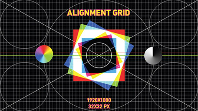
Projectors (except for LCoS laser projectors) have only one focal plane at a time. This means that only one plane in Z space is in focus at a time. Depending on the type of lens and the throw, the final plane may be relatively shallow or could be larger. The focal plane becomes a concern when using one projector to project onto multiple surfaces at different distances. If the physical surfaces are a further distance apart than the focal plane’s depth of field, you have to choose one focal plane to be in focus. This means that all surfaces outside the focal plane are out of focus. How acceptable out-of-focus content is depends on the surface, the content, and how far outside the focal plane the surface is located.
Some high-end projectors allow you to record and recall different focal planes within the built-in software of the projector and/or within the web interface of the projector. Other projectors allow you to send serial commands to the projector to control internal functions. If the projector allows you to have multiple focal planes saved and you can access the control remotely, you can change focal planes during a video blackout. This allows you to have multiple focal planes from one projector. Some media servers support triggering this kind of serial command, allowing you to program it directly into a cue. If this is not supported by the media server you have to train the operator to apply the change manually and ensure that cues relying on this change are sufficiently rehearsed.
Keystone
Whenever the projector is not perpendicular to and centered within the projection surface the resulting image is not rectangular. If the projector is off-axis the raster takes on a trapezoidal shape. If you must place a projector in a position that is not 100 percent perpendicular to the screen, then you have three options to correct the trapezoid back to a rectangle.
- Option 1—In-Projector Lens Shift: Using lens shift, described ahead, is sometimes enough to address this issue. This is the best in-projector option as it avoids losing access to all of the pixels and thus the native resolution of the projector.
- Option 2—In-Projector Keystone Correction: In-projector keystone correction introduces distortions to the content as the process effectively shrinks the image on at least three edges. This introduces scaling artifacts into the image and causes the scaled edges to become slightly fuzzy.
- Option 3—Media Server Keystone Correction: If you must apply keystone, use the media server. Media servers tend to have more robust keystone features than those available in all but the most high-end projectors. This advice holds especially true if you are doing any projection blending. When blending projectors, you warp the image in a similar way as keystone in the media server already. Adding a second layer of warping to an image typically proves difficult and further degrades the overall quality of the image.
Lens Shift
Some projectors have a feature called lens shift. This allows the projected image to move left or right, up or down, without needing to move the projector. Lens shifting can come in handy if you need to move the projected image, but cannot move the projector. Vertical lens shift is more common than horizontal lens shift, but more manufacturers are including both. The projector’s spec sheet and owner’s manual specify, if any, the amount of lens shift in each direction. When using lens shift to the full vertical or horizontal capacity you may experience issues of seeing the housing of the lens in a corner of the image. Lens shifting, especially to the extreme of what the projector is capable, causes a loss in image brightness. Projection blending is further complicated by different brightness levels between projectors. When blending, try to use the minimum amount of lens shift.

Figure 5.35
Example of horizontal and vertical keystone distortions
Source: Alex Oliszewski
Convergence
Convergence can mean two different things, so understand both applications for the term. Some technicians and designers refer to convergence when stacking or doubling projectors for brightness. Convergence in this sense means that both images are completely aligned together and is typically done to increase the overall brightness of the projected content.
Similarly, internal projector convergence deals with the technology of a projector. This does not apply to DLP and laser projectors. In all other projector types, the images are created from three separate color elements or panels, one for red, green, and blue. The projector optically combines or converges these three images together when projecting. Some projectors have better convergence than others. Sometimes, especially in older projectors, the internal convergence can become askew, resulting in one of the colors not properly aligning with the others. This looks like a ghost of the main image and is different than the slight chromatic aberrations caused by how different wavelengths of light pass through a lens. In this scenario, you need to have the projector serviced by a professionally trained technician in order to fix the internal convergence.
To complete the task of converging two stacked projectors, you need to display the same image from each projector. You can use a projector’s internal focus/alignment grid, if it has one, make one, or download one from the Internet. Then follow these steps:
- Install the two projectors, one directly above the other so that the lenses are as close and as parallel as possible without blocking any air vents or circulation around either projector. Special rigging frames that support this kind of configuration are typically available for professional-grade projectors.

Figure 5.36 Example of video projection that has lost convergence. Left: simulation of all three colors (RGB) out of convergence. Right: simulation of red out of convergence.
Source: Alex Oliszewski
- Using lens shift functions on the projectors, use the focus grid to match the two rasters as close as possible. (Some projectors include an integrated convergence method that simplifies this process.)
- In the media server, fine-tune the exact alignment using the server’s built-in corner pin and warp tool.
![]() Tip 5.4 Margin of Error
Tip 5.4 Margin of Error
It is necessary that you take any calculations you come up with as being the approximations they are. There are so many variables that, even when being very careful in one’s measurements and calculations, the results may never exactly correspond to the reality of any given setup. Anticipate a +/− variation of 5%–10% of any given calculation depending on how confident you are in the measurements and specifications you are using to do the calculations. In practice this means that if you need a projection to be a certain size, plan for it to be 5%–10% larger than you need.
Calculating Surface Brightness/Luminance
The distance a lens is from the surface is important, but not what primarily defines the illuminance of the final image. It is the intensity of the light source and the size of the final image that matter the most.
Note that a projector’s claimed ANSI lumens refers to the measurement at the light source. It does not directly translate to the illuminance of the final reflected light cast by that projector on any given surface. Footlamberts are used to calculate the perceived brightness of light reflecting off a surface. The footlambert is a luminance measurement standard and is also sometimes measured in nits or candelas per square meter (cd/m2). Note that a footlambert has a number of abbreviations, including ftL, ft-l, and fL, among others. We use the abbreviation ftL.
The formula used to calculate ftL is:
- (ANSI lumens of projector/square footage of screen area) × screen grain = ftL
The gain of a nonstandard projection surface is a particularly tricky thing to figure out without actually doing physical tests. If you are relying on your calculations without knowing the actual gain of a projection surface, remain skeptical of the calculations until the surface has a final treatment and you can actually test content on it. In most cases, you have to give a best guess. This means that you will never actually know for sure. If you are in a situation where you have to know the ftL, use a projection screen or surface treatment with a known gain.
Let’s calculate:
- The projector is 4,000 lumens
- The screen size is 20′x10 ′, so it is 200 square feet
- The screen gain is 1
- (4000/200) × 1 = 20 ftL
How many ftL are actually needed? In cinema houses, where there is little ambient light to wash out the projections, a commonly cited projection standard is 14ftL +/− 3ftL. In the theatre, where you deal with a wide range of ambient light levels, we recommend 24 ftL +/− 4ftL.
![]() Tip 5.5 Using Underpowered Projectors
Tip 5.5 Using Underpowered Projectors
Achieving the suggested minimum brightness of 20–24 Footlamberts (ftL) is often out of reach on a show with a modest budget. Because of this common reality, you may find yourself trying to use projectors that are not able to output light bright enough to get you into the 20 ftL range. The use of high-gain surfaces can help, but this works only for those sitting near the king’s seat and actually reduces brightness for those at more extreme angles.
When using underpowered projectors, ensure, if possible, that the surfaces you are projecting on have been isolated from other sources of light. Talk to the LD about the options for using side light to avoid using the same lighting angles for illuminating performers.
Since details in underpowered projections are lost first, you can compensate for this with the type of content. High contrast and graphic content result in the brightest and easiest to read images. Of course, this style of artwork needs to work artistically and dramaturgically within the play.

Figure 5.37 High-contrast line drawings mapped to the set for Death and Life of Sherlock Holmes by Susan Zeder. Directed by Jack Reuler. Set design by Todd Hulet. Lighting by Chris Peterson. (Arizona State University MainStage, 2010)
Source: Alex Oliszewski
Calculating Screen Size, Throw Distance, and/or Lens Needed
To calculate the needed screen size, throw distance, or lens, you need to know at least two out of the three elements for the three formulas. The three elements are:
- W: The width of the projection
- D: The distance from the projector lens to the screen
- TR: The throw ratio of the projector lens
To determine the throw ratio of a projector lens, check the lens specifications. Since the throw ratio of a lens is designated as two numbers separated by a colon, such as 2:1, you need to conflate the ratio into a single number. To do so, use the first number. In this case, there is a throw ratio of 2.0. When working with zoom lenses, do multiple calculations using the same sized screen width, but at varying distances within a projector’s zoom range.
The formula to calculate the width of a projection:
- D (distance of lens)/TR (throw ratio) = W (width of image size)
- Sample: 240”/2 = 120”
The formula to calculate the distance a projector is from a surface in order to create a set width:
- W (width of screen) × TR (throw ratio) = D (distance of projector)
- Sample: 120” × 2 = 240”
The formula to determine lens throw ratio:
- D (distance of lens)/W (width of screen) = TR (throw ratio)
- Sample: 240”/120” = 2.0
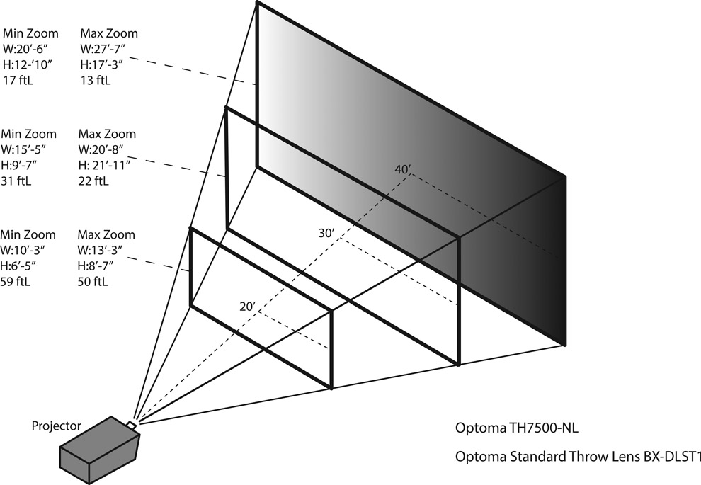
Figure 5.38
A line diagram illustrating the geometry and calculation of screen size, throw distance, and lensing
Source: Alex Oliszewski
![]() Aside 5.2 Bouncing Off Mirrors
Aside 5.2 Bouncing Off Mirrors
You can gain throw distance, which produces a larger projected image, by placing a mirror in front of the lens and bouncing the image off of the mirror. The mirror needs to be large enough and close enough to the lens to completely reflect the projection cone. Bouncing off a mirror means you lose lumens, or in layman’s terms, the image is not as bright. Losing lumens is never ideal. When using mirrors, purchase first-surface mirrors. They are costlier than common mirrors but reduce unwanted refractions and light loss. You also need to implement a solution for mounting and installing the mirror, adding an additional cost to the budget. Bouncing off mirrors is hard. It requires more complicated, precise math to reliably anticipate final image sizes. Blending multiple projectors that are bouncing off mirrors is difficult and time-consuming. Ensure the mirrors are rigid and do not bend or distort an image unevenly.
Calculating Pixel Size, Pixels per Square Inch (PPI), and Approximate Perceived Pixel Size
The pixels in projectors are made up of red, green, and blue sub-pixels that are sometimes referred to as dots. The size, contrast ratio, and intensities of these individual pixels change in relation to the viewing distance and angle from which they are viewed by the audience.
When projecting onstage we typically create large projection rasters. This risks making individual pixels visible and giving the content a very digital look. The further away the projector lens is from the surface, the larger (and dimmer) the image and the larger and more discernable the individual pixels are. There are fewer pixels per square inch, thus making them larger. Conversely, the closer you move the projector lens to the surface, the smaller (and brighter) the image, the smaller the individual pixels and the more pixels per square inch.

Figure 5.39
Line diagram illustrating perceived pixel density
Source: Alex Oliszewski
Pixel visibility is a function of the size of pixels in relation to how far away from the projection surface the audience is sitting. To calculate individual pixel sizes, you need to know the size of the screen and the resolution. Pixels are typically square, so calculating their width should also provide their height if you know the image size ratio (16:9, 4:3, etc.).
The formula for calculating the width of an individual pixel in an image is:
- SW (total screen width in inches)/RW (resolution width) = PW (pixel width in inches)
- Sample: Screen 240”W at 1920×1080 resolution
- Answer: 240”/1920 = pixel width of .125”
This does not tell you directly if individual pixels are actually perceivable to the audience. To gauge their visibility, you must also factor how far away the audience is in relation to the screen. For that we recommend calculating the perceived size of a projection’s pixels based on Paul Bourke’s formula: A = W/(N/D)
- A = the perceived subtending of a pixel in radians
- W = the physical width of the raster in meters
- N = the number of horizontal pixels
- D = viewing distance from screen in meters
Let’s consider a resolution of 1920x1080 with a 20′ (6.1m) wide screen and assign a viewing distance of 30′ or 9.14m.
- Sample: A = 6.1/(1920/9.14) = .029
This “A” should give you a good sense of whether individual pixels are visible. As a rule of thumb, if this number rises above .1 you can expect visible individual pixels and images to appear pixelated. Numbers below .02 are most likely beyond the capacity of even the keenest observer. Even if the perceived subtending of the pixel comes out within the ranges Bourke suggests, content can still end up looking pixelated depending on the levels of compression and any number of other considerations that contribute to visible pixilation in a digital raster.
For more information on this subject we recommend you refer directly to Bourke’s articles on the subject, available at http://paulbourke.net/miscellaneous/resolution.
Projection Calculators
It is possible in the age of digital computation to never sit down with pencil and paper and do the types of calculations described earlier. All major projection manufacturing companies offer online projection calculators. There are also applications you can access with a smartphone. These tools automate the process of referencing a projector’s specifications and lens configurations directly with your technical needs.
There are a lot of projection calculators available and their quality is highly variable. The tools provided by projection-centric manufacturers and online communities, such as Christie and Projectioncentral.com, are extremely robust. These calculators make it easy to calculate projection details based on specific models and lenses offered by manufacturers.
There are a large number of projection calculators directly tied to a database of specific projectors. This can mean that you end up having to try a few calculators before you find one that references any given projector. When working with off-brand projectors, mileage can vary.
Projection calculators are particularly helpful for visualizing the change in a projection’s illumination based on its size. They typically allow you to simply move a slider back and forth and see the levels change in relation to one another.
When manufacturer-specific calculators are not readily available, we recommend the calculator provided at ProjectionCentral.com. As of this writing they also offer an iOS app called ProjectorPro. For iOS, we also recommend an app called ProjectorCalc. A third iOS app we use regularly, Projectionist, includes calculation schemes that help deal with the concepts of projection blending. Some of these apps also provide calculations for pixels per square inch and footlamberts.
By the time you read this, these websites or apps may no longer exist. Regardless, with some online searching you can find a projection calculator that fits your needs.

Warping and Projection Mapping
Warping, also known as geometry correction and projection mapping, is used to ensure a projected image looks correct on nonplanar surfaces or when the projector is not aligned properly with a flat surface. There are different types of warping, from basic four-corner pinning that duplicates the functionality of keystone to complicated Bézier warps needed when dealing with curved or complex geometric shapes.

For most theatrical applications, the warping and detailed mapping are done in the media server. But this also is accomplished by professional stand-alone software, which passes the output of the media server through it or by creating your own custom software application.
When mapping content using multiple projectors, media servers route what part of the image needs to come from which specific projector, based on the surfaces you create in the server. Each media server has its own method and application for warping/mapping, but they should all provide a basic quad corner pinning method of some sort using a simple quad surface. They should also provide a more complex Bézier surface to create curved shapes.

Figure 5.42
Comparison of a warped (top image) and unwarped (bottom image) projection
Source: Alex Oliszewski
A quad surface is a polygon that has four straight sides and four corners. By clicking and dragging on one or more of the four corners, the quad is warped, distorted, stretched, and so forth to match any four-cornered surface. Most warping/mapping applications allow you to add or remove points to create more complicated (triangular, octagonal, etc.) sharp angled surfaces. More advanced media servers give you an option to start with different shaped surfaces, such as circles, rather than only squares.
For complex surfaces that include rounded edges, a warping tool that supports Bézier points is used. Each Bézier point has two control points, allowing for the lines to become curves. Most media servers also allow you to add Bézier points on a surface to create more complex surfaces.

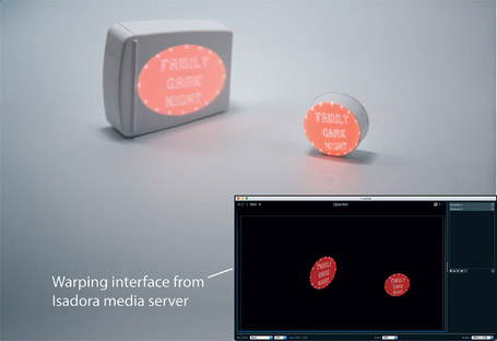
Figure 5.44
A single projector creates discrete areas of video mapped onto separate surfaces. Note the image on the left is out of focus because of depth of field on the camera, not necessarily because of the projected focal planes.
Source: Alex Oliszewski
Once you have a warped and mapped surface, you apply content to that surface. The media server places the content (a texture) onto this warped/mapped surface and the content now automatically matches the shape of the warped/mapped surface and appears correct when projected.
Powerful digital tools now common in high-end media servers, such as d3, allow for the semi-automated process of mapping three-dimensional content directly to actual three-dimensional objects.
Warping and mapping are a graphics-intense process. More robust media servers take advantage of the graphics card to process warping and mapping rather than the CPU.
Masks
Masks can mean a few different things when working with projectors. Masking features in a media server usually refer to the ability to hide or reveal content using a premade or custom image with an alpha channel. This is a common process used in Photoshop. Most servers deal with these types of masks by using either luma or chroma functions. This means that masks are either black on white or white on black. If the mask is a black circle on a white background, the server can use the circle in two ways to reveal an image below the mask. One way cuts out the actual black circle, revealing the image below within the circle. The other method does the exact opposite, revealing the image below on only the outside edge of the circle.
Masks are also used to frame the edges of video. This is useful when wanting a custom edge or shape for the content to live within. Masks can also insure that only video black falls outside of a defined area/shape.
Using Multiple Projectors
Multiple projectors are often used to gain more surface area to project onto. If you need to create a single large surface, you most likely need to edge blend multiple projectors. Or you may have multiple discrete surfaces that you cannot hit with one projector position, so adding an additional projector makes sense. In some cases, you may use a mixture of rear and front projection. Other times you may have surfaces that are on drastically different focal planes and need multiple projectors to ensure proper focus on all surfaces.

Figure 5.45
Video masked to the interior (top) and exterior (bottom) of an oval mask
Source: Alex Oliszewski

Figure 5.46 Left: PNG mask created in Adobe Illustrator. Right: PNG mask used in the production of Count of Monte Cristo , by Frank Wildhorn and Jack Murphy. Digital media design by Daniel Fine. Set design by Rory Scanlon. Lighting design by Michael Kraczek. Costume design by La Beene. (Brigham Young University Mainstage, 2015)
Source: Daniel Fine

Figure 5.47
Three projectors installed for edge blending
Source: Alex Oliszewski
As discussed in the convergence section, another reason to use multiple projectors is because a brighter image is needed. In this scenario, you stack the projectors and project the same content onto the same surface from two aligned/converged rasters in order to increase the brightness of the projection at the surface. An added bonus of stacking projectors is that there now is a built-in backup in case one projector fails.
Whenever using multiple projectors even without edge blending, you make the system more complex. Make sure the graphics card can support multiple outputs and at the needed resolutions.
Whenever edge blending or stacking, use the same make and model projector. This is the only way to guarantee that color temperature and image size is relatively the same. Due to the amount of lamp hours each lamp has on it, brightness and color temperature can vary between projectors even if they are the same make and model. Make sure that all menu settings on each projector match to ensure best results.
Blending
When overlapping projected images, the overlapped area is twice as bright. Blending the edges of the two overlapping images solves this problem. Every media server has different features and methods of edge blending. However, the underlying process is basically the same for all of them. Some servers may not support edge blending at all.
Before blending, the edges of at least two projectors must overlap so that one large image is created. The pixels that are in this overlapping region are blended across the entire overlap. There are four steps to create the overlap:
- Calculate the required overlap.
- Physically align the projector rasters to the calculated overlap.
- Adjust the media server’s blend function to the same percentage of overlap.
- Adjust the gain, gradient, or blend ramp amount (depending on how the server refers to this setting) in the media server until the overlapped area is obfuscated.
Step 1: Calculate the Overlap
The ideal overlap is around 20 percent. For this example, there are two 1920x1080 projectors side by side with a 20 percent overlap. To calculate overlap:
- Determine what 20 percent of the width of the image is by multiplying 1920 × 20 percent = 384 pixels.
If you do not get a whole number, round up. Do not try to overlap and blend half pixels.
![]() Tip 5.6 Determining Final Raster Size With Multiple Projectors
Tip 5.6 Determining Final Raster Size With Multiple Projectors
Two 1920×1080 projectors:
- Add: 1920 (resolution of projector 1) + 1920 (resolution of projector 2) = 3840 pixels wide.
- Minus: 3840−384 (20 percent overlap) = 3456 pixels
- Final raster size after 20 percent overlap = 3456×1080
Step 2: Align the Projected Rasters to the Calculated Overlap
The layout of projectors varies depending on the hanging positions, screen size, geometry of the surface, and the optics of the projector lens used. We recommend using a projection grid on each projector to help see the overlap on the surface. Based on the resolution of the projectors and the percentage of overlap used, it is sometimes helpful to create a custom projection grid for each projector with the corresponding number of overlapping pixels highlighted.
Step 3: Adjust the Media Server’s Blend Function to the Same Percentage of Overlap

Figure 5.48 Line drawing of two 1920×1080 projector rasters with a 20 percent overlap. Not to scale.
Source: Alex Oliszewski
Once the projector’s rasters are aligned and properly overlapped, the media server’s blend function needs adjusting to match the physical overlap of the projectors. The amount of overlap required is a function of the amount of gamma correction needed and the dynamic range of the software’s blend function. Media servers usually automate this process and hide the details from you.

Step 4: Adjust the Gain, Gradient, or Blend Amount in the Media Server
The blend or gamma function works by placing a gradient over the blend area to decrease the luminance from one image as the luminance from the other increases. Most servers allow for manual input of the gain/gradient/blend amount.
The ideal gamma mode for blending uses a linear gamma ramp. Most projectors provide different image modes, which automatically adjust gamma levels, such as “standard,” “film,” “photo,” “office,” “cinema,” “bright,” or “gaming.” Before setting up projection blends, make sure to choose a mode with a linear gamma. If the projector manual does not specify the gamma type, flip through the different image modes on the projectors to see which produces the best blend. Make sure to match the mode on each projector. If the media server has an option for gamma control, choose linear.
A check list for creating the best blends:
- Use matching projectors. Same make and model and age.
- Use lamps with the same number of lamp hours (usage) on them.
- Use DLP or laser projectors with high contrast ratios and dark video blacks.
- Make sure “dynamic gamma” and “dynamic contrast” settings on the projectors are turned off.
- Ensure that the gamma value/image modes on the projectors and media servers are set with a linear ramp, typically labeled as “film” or “photo” modes.

Figure 5.50
Screenshot of QLab’s (top) blend gamma tool to control blending settings and one of Isadora’s (bottom) edge blend mask controls/actor
Source: Alex Oliszewski

Figure 5.51 Example of linear gradient used in a three-projector blend during construction of Forbidden Zones: The Great War , a devised new work, conceived and directed by Lesley Ferris, codirected by Jeanine Thompson, with the MFA actors and designers. Set design by Cassandra Lentz. Digital media design by Alex Oliszewski. (The Ohio State University Mainstage, 2017)
Source: Alex Oliszewski

Figure 5.52 Example of a final image created from two blended projectors from Johnny Appledrone vs. the FAA , story by Lee Konstantinou. Directed/performed by Don Marinelli. Digital media design by Daniel Fine. Emerge Festival. (ASU Center for Science and the Imagination, 2015)
Source: Dana Keeton
Projector-Related Equipment
Manufacturers are always releasing new projector-related equipment, so there may be new and exciting gear already in use or available in the near future.
Lamps
Most video projectors use one or multiple lamps as their light sources. The lamp is what produces the bulk of the heat within a projector. Different lamps use various elements to generate light, such as Xenon and Mercury Vapor. Expect slight color variations between different element types.
Projection lamps degrade over time, reducing the brightness and eventually developing flickering and other visible artifacts, such as color shifting. The lifetime of a lamp is rated in hours, with most expecting 1,000–2,000 hours of use before replacement. If budget allows, consider replacement of lamps no later than at 75 percent of their rated lifetimes to maintain rated intensities and reproduction of color. Most projectors include a lamp lifetime counter that tracks lamp hours. You may have to reset this timer manually when installing new lamps.
Projectors often have built-in sensors able to tell when a lamp is beginning to fail and sometimes display a warning when near failure. A key indicator that a lamp is on the edge of failure is when a projector needs to strike, the first step in powering up a lamp, multiple times before remaining on. The lamp failure may be accompanied by a clicking noise and small flash of light that immediately dies.
Have at least one complete backup set of lamps for the projectors at all times that a show is in production. Projection lamps are normally special-order items. If a lamp goes out on opening night of a two-week run, you may be hard-pressed to get a replacement in a timely fashion. Make sure to budget for replacement lamps as they tend to be expensive. When blending multiple projectors, ensure the lamps in both projectors are roughly the same age to avoid noticeable color and illuminance variations between them.

Figure 5.53
A projector lamp
Source: Alex Oliszewski
Dowsers
A dowser is a device that physically cuts the light coming out of a projector. Dowsers are a near mandatory piece of projection equipment. In theatre productions, it is desired for the projection department to accommodate a true blackout cue, meaning not just throwing projector black but projecting no light at all.
There are many creative ways one might possibly dowse a video projector. Some high-end video projectors come with built-in dowsers but their inclusion is rare and they are sometimes loud enough to make an audible clicking noise that may be distracting in a quiet moment between scenes. We have found great success using DMX-type paddle dowsers, like the one displayed in figure 5.54. They are quiet and trivial to cue with most media servers as they rely on DMX.
It is not uncommon for a digital media designer to coordinate a dowser’s operation with the lighting designer to drive the dowser via the DMX with the light board. If the LD is going to control the dowser, you need to coordinate with her in tech, so she can program those cues. Ask the LD to put the dowser on a slider, so that in a media server emergency situation the light board operator can, with a single button press or slider operation, manually dowse the projector(s). Modern media servers and a prevalence of USB to DMX control adapters allow you to control them directly.

Figure 5.54
A DMX-controlled dowser installed on a projector (inset, back of dowser)
Source: Alex Oliszewski

We recommend you always include dowsers in your digital media designs and schematics when using projectors.
Mounts and Cages
Projector mounts are special attachment devices for projectors that allow for easy installation from ceilings, lighting grids, and so forth. Different types of mounts are available for any given projector and we recommend you coordinate with the theatre’s technical director and lighting designer to ensure that any mount you choose is compatible with the type of grid pipe or another surface you hope to mount the projector on. Some mounts have tilt and pan features specifically designed to aid in the aiming and alignment of a projector once it has actually been mounted in place. We recommend investing in mounts that have these types of features. You may need to train the board operator or appropriate technical staff in how to use these features to ensure they can address any issues that come up during the run of a production.
Projector cages are used as an installation method for large projectors that are too big for a mount’s capacity. Cages also serve as a method to protect projectors and sometimes allow multiple projectors to stack on top of one another. If the projectors are installed on a table in a projection booth–type setup, we still recommend using a cage.
Projection Screens and Surfaces
Manufacturers offer a wide array of projection screen products for nearly any application, including paints and glazes made for projection applications. Projection screens are expensive and smaller budgets often demand creative solutions. In the theatre, it is not uncommon to use surfaces not specifically designed for projection, such as muslin, off-color cycloramas, walls, tables, set pieces, screen door materials, and performers. When not projecting onto actual projection screens or surfaces specially treated for projections, always test the projection on the surface with enough time to address any issues that may arise.
![]() For More Info 5.5 Projecting on Muslin and Tips for Making Any Surface More Reflective
For More Info 5.5 Projecting on Muslin and Tips for Making Any Surface More Reflective
See “Aside Projecting on Muslin and Creating Frames with Soft Goods” in Chapter 2.
Screen Gain and Viewing Angle
Screen gain represents how intensely a given surface reflects (front projection) or transmits (rear projection) light. Gain is measured by a ratio scale and represented by numbers:
- 1.0: considered the standard or reference gain
- .5: reflected brightness is reduced by 50 percent
- 2.0: reflected brightness is increased 100 percent
Screen gain and viewing angle are closely correlated. As screen gain increases, the intensity of an image at off-center viewing angles decreases. The viewing angle for a screen is the full range of angles, from the far left to the far right of center, an image is viewed at before the image is reduced by 50 percent from the center. A higher-gain screen is not necessarily always better, as it decreases viewing angle. High-gain screens can reveal hotspots and encourage color shifting, since all colors may not amplify at the same levels.
Since the levels of ambient light constantly change during a show, which affects perceived brightness of projections, it requires a balance between high screen gain or wider viewing angle. If the projections are always in bright or dim lights then you might favor a high or low gain surface, respectively. However, if a surface needs to work across a wide range of ambient light levels, a 1.0 gain should provide the best flexibility for projecting in both higher and lower levels of ambient light.
When dealing with screens and surfaces specifically made for projection, gain is usually listed within the specifications. However, when projecting onto floors, set walls, or other types of materials, such as muslin, which are not specifically made for projection, specific gain information is not readily available. To measure the gain of a surface, use a gain reference card (traditionally this was a board coated with magnesium carbonate) purchased from a projection or screen manufacturing company or a piece of a known 1.0 gain surface/screen. Put the card in front of a projector casting white light at the same distance as the surface you are testing. Use a light meter, such as a Minolta LS-10, to first measure the card and then measure the unknown surface. Then compare the meter readings between them to establish the gain of the unknown surface. Use Andrew Robinson’s formula to calculate the gain:
- Screen gain = (surface meter reading in Ftl)/(card meter reading in Ftl)
If possible, perform the tests with the same equipment and distances specified in your design. Consider a full range of ambient light levels when testing.

Front and Rear Projection Screens and Fabrics
Projection screens have been specifically designed to accommodate projections and are designed for front projection (FP), rear projection (RP), or both. RP screens tend to provide a brighter image with more perceivable contrast than FP. However, unless RP screens are specially manufactured they are more prone to reveal a bright hotspot, indicating the location of the projector’s lens.
You can find screen materials that are made of plastics, such as PVC, or fibers, such as cotton. PVC type screens typically have no texture on their surfaces and produce sharper images as they do not scatter light like a textured surface does. Plastic and fabric projection screens typically need to be stretched in order to remove creases and folds on their surface. This is done either with a tension frame or the use of pipes and weights. Screens may be prefabricated or sold on a bolt like fabric, leaving it to the theatre team to fabricate rigging points and frames or pipe pockets. Consider how to apply tension to a projection screen when fabricating your own.

Figure 5.57
Example of projection on a front projection screen
Source: Alex Oliszewski
Here are some considerations when using projection screen materials:
- There are a number of colors that projection screens come in, each appropriate for use in different situations. In general, there are three main colors of screen: white, gray, and black. White screens are used when high gain is needed and are common in the world’s cinemas. Gray screens, more typical in theatrical settings, help preserve image contrast and are used when the amount of ambient light is a concern or if the projector is particularly bright. Black screens are used in environments with extremely high levels of ambient light or when a screen’s existence within a set needs to be obfuscated as a surface that automatically reads as a projection screen.
- When screens are placed between audience members and the speaker system they can effectively muffle and distort the sound elements coming from the speakers. There are special types of projection screens that are perforated in ways that allow them to cause less distortion of audio and are considered acoustically transparent.

Sharkstooth Scrim
Sharkstooth scrim represents the textile technology behind one of theatre’s most magical special effects. In this trick, a scrim can at moments seem opaque and at others invisible. When a lighting designer illuminates a sharkstooth scrim from an extreme front angle it is perceived as opaque as the structure of its surface glows and seems solid. When a scene located behind the scrim is illuminated using back light or low-angle front light, the light shines through the holes in the scrim and it becomes indistinct.
When projections fall on sharkstooth scrim they can appear ghostly, as though they are floating in empty space. Since front projection casts light through the scrim, whatever surface is behind the scrim catches the light and creates a double image. Consider using an extreme projector angle, so you can bury the image passing through the scrim below or above sightlines if this doubling is undesirable.
Emissive Displays
Typically used in concerts and for amplification at corporate events, emissive displays are gaining popularity in the theatre. This trend should most likely continue to expand as emissive technologies become cheaper and easier to program. Emissive displays are typically brighter than projections and often designers do not use them at 100 percent brightness.
LED Displays
An LED display is a flat panel made of an array of light-emitting diodes. Each diode serves as an individual pixel in the display and can be independently programmed/addressed. Because of their brightness, LED displays are commonly used outdoors in daylight and are becoming ubiquitous with advertising for use as billboards and general signage. They are a great option for the stage due to their brightness and flexibility in combining multiple LED fixtures to create massive emissive displays. They do tend to have low resolutions and are prone to making content seem pixelated when viewed at close ranges.
There has been a boom in LED displays in the recent years. It can be overwhelming to decide on a manufacturer and model when choosing to use LED displays. When choosing LED displays, consider the edges, weight, resolution in relation to audience viewing distances, pixel pitch, and power consumption. Common LED displays include:
- Panels
- Walls
- Tiles
- Flexible curtains
LED displays usually come with their own control boxes that are programed in a process called pixel mapping. Special interfaces are typically provided by the display manufacturer that aid in the scaling and translation of video data. Features vary widely between products so make sure any display used is compatible with the media server and/or design needs.

Figure 5.59Top left: white scrim with projection and no back light. Bottom left: white scrim with projection and backlight. Right: DIY silver scrim made from screen door material, cut and sewn into different sizes, from House of the Spirits by Caridad Svich, based on the novel by Isabel Allende. Digital media design by Alex Oliszewski. Set design by Brunella Provvidente. Lighting design by Anthony Jannuzzi. Costume design by Anastasia Schneider. Directed by Rachel Bowditch. (Arizona State University Mainstage, 2012)
Source: Alex Oliszewski
Monitors/TVs
Monitors and TVs have practical applications both onstage and backstage. Oftentimes a computer monitor or a TV is all a theatre owns or has access to for use onstage. For intimate spaces, a few monitors or TVs may be exactly the right type of emissive display in terms of both technology and aesthetics.
You also have to contend with monitors for work backstage and during tech. Different media servers require that you have a control monitor that matches the resolution of the onstage displays.
Common types of emissive displays:
- LCD
- LED
- OLED
- CRT
- Tube (increasingly rare)
Cameras
In the theatre, cameras are used to create still and moving images, as well as for live video capture and sensor work. Digital cameras of all types are becoming more compact, powerful, and affordable every day. Analog film and videotape cameras are still in use, but are increasingly rare. There are many different types of dedicated video cameras and DSLR cameras that shoot both photos and high-quality video. IR cameras drive real-time effects, small cameras can be hidden in a set for a special moment, and thermal or IR cameras allow tracking of stage crew in a full blackout.
Camera Basics
Aperture
Aperture is the opening in the lens through which light travels. The easiest way to understand this is to think about aperture like the pupil of your eye, which is what all lenses try to simulate. If you are in a dark room, your pupil gets bigger to let in more light. If it is a bright sunny day, your pupil gets smaller to let in less light. This is the basic principle of aperture.

Figure 5.60
Camera f-stop settings showing examples of depth of field
Source: BeeBright/Shutterstock.com
In optics, the diaphragm (which controls the aperture) works exactly like the iris in your eye. It mechanically opens and closes to let more or less light in. Aperture is measured in f-numbers, known as f-stops. F-stops describe how open or closed the diaphragm is. The tricky part is that the measurement is counterintuitive. The higher the f-stop number, the smaller the opening, and conversely, the smaller the f-stop number the larger the opening.
The aperture directly affects the depth of field, or an image’s sharpness and areas of focus. A larger f-stop creates a greater depth of field, allowing for subjects both in the foreground and background to be in focus. A small f-stop separates the foreground from the background, causing anything outside of a relatively narrow focal range to be blurry and out of focus.
Aperture settings work in concert with shutter speed and ISO settings to determine the final exposure of an image.
Shutter Speed
The shutter is a device that opens and closes at variable speeds and allows light to pass through a lens and aperture before falling on the camera’s sensor. Shutter speed is also referred to as exposure time. Shutter speed is measured in fractions of a second and defines the amount of time the shutter is open. The longer the shutter is open, the brighter the resulting image is. Shutter speed also helps control how movement in an image is rendered. A long (slow) shutter speed creates what is called motion blur, where a moving subject appears blurry in the direction of its motion. Long shutter speeds are used to deliberately add motion blur and provide an image with a sense of action. A fast shutter speed reduces motion blur and can help freeze subjects in mid-action.

Figure 5.61
Camera shutter speed settings showing examples of motion blur
Source: cbproject/Shutterstock.com
Shutter speed works with aperture and ISO to determine exposure.
ISO
ISO is short for International Standards Organization and is used as an industry scale for measuring light sensitivity. On digital cameras, ISO settings control the light sensitivity of a camera sensor. The higher the ISO number, the more sensitive to light and the lower the ISO number, the less sensitive. Increasing the ISO allows the sensor more responsiveness in low light, but it also degrades quality because it adds grain or noise to the image. ISO numbers usually start at 100 or 200 and increase in value in multiples of two. Each increase doubles the sensitivity of the sensor. If possible, avoid using high ISO numbers.
ISO works with aperture and shutter speed to determine exposure.
White Balance
Light sources have different color temperatures, which render and balance color differently. White balance is a setting that allows a camera to reference what white is in any given lighting situation and insures realistic color reproduction of an image. Most cameras have several preset white balance options or have the ability to manually choose the white balance. Shooting in LOG/RAW allows you to change the white balance settings in postproduction.

Digital Image Sensors
Analog cameras capture light onto film using a chemical process. Digital cameras record light, via a sensor(s), as variable analog charges. These charges are then converted into digital numbers for storage onto some form of storage device, such as compact flash cards. The two most commonly used digital camera sensors are: CCD (charge-coupled device) and CMOS (complementary metal-oxide-semiconductor).
Digital cameras have a fixed number of colors that are represented and a maximum resolution. While the size and density of a sensor’s light receptors help determine resolution, the ADC (analog-to-digital converter) that converts the charges produced by a sensor into digital data also defines the final image’s depth of color and image quality. Digital cameras also include a DSP chip (digital signal processing) that adjusts the detail and contrast of the image and then compresses the data for digital storage. High-quality cameras include large resolution sensors and high-quality versions of these other components.
DSLR

Figure 5.63
Left: properly white balanced image. Right: same image with a white balance color temperature setting of 50,000 k.
Source: Alex Oliszewski
A DSLR (digital single-lens reflex) is a digital camera that combines a digital imaging sensor with the optics and mechanisms of an analog SLR (single-lens reflex) camera. The design of the reflex system is the main difference between a DSLR and other types of digital cameras, allowing you to look through the viewfinder (or LCD screen) and see exactly what the camera captures.
In a DSLR, light travels via the lens to the reflex mirror that moves between two positions—one that allows the light into the viewfinder and the other that when a photo is taken allows the light to the sensor and the image processing system. Like all digital still cameras, DSLRs have image processing electronics like signal amplifiers, analog-to-digital converters, contrast adjusting chips, image file encoding and compression systems, and so forth.
Professional DSLR cameras, such as the Canon D5 Mark III and IV cameras, have many great advantages over most consumer cameras, which include:
- Interchangeable lenses with wider range of depth of field
- Advanced optics
- The ability to record HD and 4K video
- Larger sensor sizes
- Better image quality
- Wider angles of view
- Faster and more responsive performance
- Better and faster autofocus methods
- Higher frame rates for video
Video Cameras
Consumer and professional video cameras are often referred to as camcorders. Most affordable camcorders have fixed lenses. The term camcorder came about to describe portable, self-contained devices that could both record and play video. Digital video cameras work in basically the same way and have the same components as digital still cameras.
Higher-end video cameras use three sensors as opposed to one. Behind the lens is an optical prism block, which separates the light of an image into three primary colors—red, green, and blue—and directs each color to its own CCD sensor. Three CCD sensors produce a higher-resolution image with finer grain and better color than a single-sensor camera.
As digital video cameras like the Blackmagic cinema series and the Canon 5D Mark IV become more affordable and postproduction techniques allow for increased manipulation of LOG/RAW video files, it is increasingly possible to capture high-quality footage for the theatre at affordable prices.
Cameras for Live Video
Camcorders are commonly used for live video. Depending on budget, mid-level consumer to entry-level professional camcorders are most common. Due to issues of latency and cable length runs, a camera that has built-in SDI outputs is ideal. Use a camera that works well in the low-light situations typical in theatre productions.
A lightweight camera and one that has a flip-out view screen is often helpful for camera operators, especially if a performer is using the camera. Make sure to use a battery with enough life to last for each act of the show. You can swap in a fresh battery at intermission. Some cameras have accessories that allow you to plug them into a dedicated power source. If small amounts of latency or video dropout are not a concern, it is possible to use HDMI to wireless adaptors. This allows an onstage camera to become more portable by transmitting the video signal to the media server wirelessly instead of via a cable. Thoroughly test such a system before use in a production.
Some shows make good use of low-end security cameras. These cameras are usually fully automatic and don’t have any control of zoom, focus, f-stop, and so forth, so they are not right for all applications. However, if the image they produce fits into your aesthetic they are an option as they are cheap and easy to set up.
Another type of camera that is sometimes used for live camera feeds in theatre is PTZ cameras. PTZ stands for pan, tilt, zoom. These cameras are great to use because one operator can control multiple cameras remotely. Higher-end PTZ camera systems can also record different camera positions, focus settings, exposure settings, and so forth, so an operator can hit a single button to shift between predetermined settings. Some of these cameras settings can be triggered via a media server through a serial interface. More typically, however, using a PTZ camera system requires a second, dedicated interface for a board operator to control.

Latency
Latency is suffered across all areas of computing and generally refers to the amount of time between when a computational task is triggered and the requested output is delivered. For example, the latency of turning a phone on depends on whether it is powering up from its sleep mode or it needs to reboot from a completely unpowered state.
Digital media designers need to understand and explain latency most often when dealing with live digital video streams. The movements of the live performer onstage and his or her projected form should be in sync, so any notable amounts of latency between the two can produce a disjointed and unwanted echoing of movements. As a rule of thumb, the more effects and types of manipulations applied to a live video stream, the more latency is introduced.
The best way to avoid latency in a live video signal is to use dedicated video hardware for each step of live video capture, mixing, distribution, and display. For example, chroma keying is an expensive computational task that can introduce noticeable amounts of latency in a media server. By using a professional video mixer that includes a chroma key feature, the post-capture effects are offloaded from the media server, reducing the overall latency in a system.
A few common ways of mitigating latency in a live video stream include:
- Reducing the resolution
- Minimizing the number of real-time effects
- Utilizing the fastest possible connection ports available on the computer’s motherboard, typically some form of PCIe
- Using dedicated hardware to avoid bottlenecks in the computational process
Lighting for Live Cameras
In video production lighting is set up for the camera, while typically most lighting onstage is not. How a subject looks through the camera is altered a great deal by the lighting onstage. Lighting is almost continuously shifting in a typical theatre performance, making it difficult to properly set the exposure on the camera in a single place that works for every moment. There are a number of low-cost, dimmable LED lights that mount to cameras or can hide in the set. If more light on a performer is needed, these can offer a viable solution. Work with the lighting designer to properly light subjects for video cameras.
Video Capture Cards and Devices

Figure 5.65
Left: internal capture card. Right: external capture device.
Source: Alex Oliszewski and megastocker/Shutterstock.com
In order to receive or capture a video signal the media server must have either an internal video capture card or an external video capture device. Capture devices have analog and/or digital inputs. Capture cards connect directly to the computer’s motherboard, while external capture devices connect to the computer via USB 3.0, Thunderbolt, and so forth. For this reason, internal capture cards attached via a PCIe slot generally provide for faster transfers of video streams, thus having lower latency. Common professional models used in the industry are made by Blackmagic Design, Datapath, AJ, and Gefen.
Video Production Gear
Having your own small professional video production kit can serve you well. In this section, we recommend all the needed gear for a professional entry-level kit.
Camera Kit
If possible we suggest owning two cameras: a high-end DSLR, such as the Canon 5D series, and a dedicated video camera, such as one of the Blackmagic digital cinema cameras. A professional DSLR allows you to shoot both photos and video to use as content in your designs. It also allows you to document a completed work. If you can afford both cameras, purchase a dedicated video camera that has the same lens mount as the DSLR, so the same lenses can be used on both cameras. Conversion kits for lenses exist, but rarely provide the same quality as the native lens. In addition to a standard kit lens, consider investing in telephoto and wide-angle prime lenses.
Here are some essential items to round out the camera kit:
- Camera bag
- Lens cleaner

Figure 5.66 Canon 5D camera kit
Source: Daniel Fine
- At least two 16, 32, 64, or 128 GB storage cards. They come in different speeds and you should get the fastest your budget allows, as the read/write speed of a card directly impacts the camera’s responsiveness in writing recorded data to the card
- At least two batteries per camera and a wall plug
- UV lens filter for each lens. This blocks UV light and also protects the lens
- Professional fluid head tripod with a quick leveling system. We recommend Manfrotto tripods as they are particularly rugged and reasonably affordable
Audio Kit

Figure 5.67
Zoom H4n audio kit
Source: Daniel Fine
For the best, cleanest audio, record to an external device. Here are the essentials of an entry-level audio recording kit:
- Audio kit bag
- Field audio recorder, such as a Zoom H4 or Tascam DR-40, both solid, portable, entry-level models
- Closed ear headsets to monitor recording level
- Shotgun microphone with a boom pole, camera mount, and mic stand
- Two lavalier microphones, receivers and transmitters

Light Kit
Owning a basic three-point light kit allows you to light a variety of subjects. In addition to a traditional light kit, owning a small, portable LED light or two comes in handy in a variety of situations. Inexpensive lights are usually made from cheap plastic components and break faster than a more rugged, brand-name kit, such as ARRI. The three-point light kit should include:
- (1) 650–1,000 watt light with a softbox
- (1) 500–650 watt light, with a softbox, if budget allows
- (1) 150–300 watt light
- (3) Light stands
- (3) Barn doors
- (3) Portable sandbags
- Spare lamps
- Heat-resistant work gloves
- 1–3 reflectors
- Miscellaneous gel and diffusion
- Travel case
Miscellaneous Video Gear
There are a number of miscellaneous items that round out a video production kit. They include the following:
- An iPad or tablet. Depending on the camera, apps are available that enable a tablet for use as an external monitor and also to remote-control the camera’s settings. A tablet can also serve as a slate and a teleprompter. Other useful apps can be installed for basic photo and video production and even editing
- 1–3 C-stands. A C-stand is a heavy-duty stand similar to a light stand. They can hold many different types of objects and are extremely handy for mounting lights, baffles, cookies (similar to a gobo), and so forth
- Sand Bags
- (3) 25′ and (3) 50′ power cables
- 1–3 power strips
- Gaffer tape
Editing System

Figure 5.69
Impact C-stand with sliding legs
Source: Daniel Fine
Given that digital media design is all about different types of content creation and manipulation you most likely already own a high-powered computer to create content and edit video. At the very least you need a top-of-the-line laptop (either Mac or PC) for professional editing and animation. In addition to the laptop your editing suite should include:
- An external monitor
- Keyboard
- Mouse with scroll wheel
- External hard drive
- Adobe CC or equivalent
- 3D software

Networking
A local area networking system allows for multiple devices, such as media servers, projectors, and light boards, to link to the Internet and locally to each other via different types of communication protocols and channels. It is not recommended to allow the media server or other gear access to the Internet directly, since firewalls are typically deactivated and the risk of viruses becomes greater. Networking allows the different computers and equipment to communicate with each other and to transfer and/or share video, audio, and other data. In order for the various gear to talk to each other, everything must be on the same local network. Different equipment can connect to networks wirelessly and/or via Cat 5/6 cables.
Open Sound Control (OSC)
OSC is a popular communications protocol in the performing arts. It is typically used to coordinate and transfer number-based data between computers, synthesizers, sensors, and other devices. OSC is more flexible than MIDI and avoids most of its limitations. For instance, channels of data sent via OSC are not limited to 255 steps and can use floating point numbers and even send large groups of changing values together in a single channel. Because OSC is built on top of the non-error checking network standard UDP, it shares this standard’s relativity low latency, while also tolerating drops in signals.
OSC can be particularly useful when used to enable remote control of a media server through a wireless network. Media designers often need to get up and move around on a stage to look at content and work with projector outputs when away from the tech table. Time and again we find ourselves walking back and forth between the stage and media server to fix issues on the set or check the placement of a warp.
Isadora and other OSC enabled servers allow the quick networking of portable tablet computers, such as an iPad, that in turn use apps such as Touch OSC or Lemur to allow the remote control of server settings. Once networked, via OSC to the server, these apps allow for linking controls and buttons to an iPad interface. This allows the designer to adjust warps, trigger media cues, and otherwise remotely control the main system while wandering the stage or the house of the theatre. This is also a useful method for remote operators and performers to control a media server.
Safety tip: UDP and OSC do not use error checking as TCP/IP does. While this improves latency, it means OSC is prone to false signals and dropped triggers. Do not use UDP or OSC to drive the speed of scene change motors or trigger events that have any potential to harm performers or crew.
DMX512-A
DMX512-A stands for 512 channels of digital multiplex data. It is typically referred to simply as DMX. This communication standard was developed for the control and cueing of stage lighting fixtures and effects. There are two plug types, a five-pin version and a popular three-pin version that matches the XLR-type cables used by audio equipment. Confirm which cable type the equipment uses before investing in cables. DMX devices are designed to be daisy chained with one another, allowing the control of many different devices without each one needing an individual run of cable sent to it.
DMX is commonly used in theatre lighting products. Digital media designers most frequently use this standard to run DMX-enabled dowsers. By using USB to DMX adapters, most modern media servers are able to control DMX fixtures directly without having to interface with a lighting board or rely on the lighting designer to program dowser cues in their system.
A DMX network is referred to as a “DMX universe” and has a limit of 512 channels. If each device in a universe requires two data points, say, the x and y of a moving head mount, that means that 256 devices can run per DMX universe (512/2 = 256). High-end lighting boards and DMX controllers are able to address multiple DMX universes.
Safety tip: DMX does not use error checking as TCP/IP does. While this improves latency, it means DMX is prone to false signals and dropped triggers. Do not use DMX to drive the speed of scene change motors or trigger events that have any potential to harm performers or crew.
MIDI
MIDI, standing for Musical Instrument Digital Interface, is a popular standard for networking electronic instruments and computers. It uses a music-inspired channel-addressing scheme. Each channel of MIDI is limited to transmitting whole numbers between 0 and 127 (sometimes listed as 1–128) on a maximum of sixteen channels. MIDI is typically used in music production, but can be implemented for similar control and communication as OSC.

Figure 5.71
Pallet Gear MIDI interface that can be programmed and configured for customized control of a media server
Source: Alex Oliszewski
There are affordable USB to MIDI adapters that digital media designers can use to trigger content. Typical devices that use MIDI are VJ controllers, keyboards, specialized drum pads, or specialized control surfaces, such as those made by Pallet Gear and KORG. They can be used to great effect when large physical buttons are preferred over a TAB key or space bar on a keyboard.
Art-Net
Currently in its fourth version, Art-Net is an extension of the DMX standard that is sent over Ethernet cables using the UDP networking protocol, instead of DMX cables. Art-Net helps overcome the channel limitations of DMX by sending multiple DMX universes over a single Ethernet cable. For devices that do not natively support Art-Net there are transmitter/receiver-type adapters available. Some digital media servers, such as QLab 4, now include native support of Art-Net.
Safety tip: DMX and Art-Net do not use error checking as TCP/IP does. While this improves latency, it means DMX and Art-Net are prone to false signals and dropped triggers. Do not use DMX or Art-Net to drive the speed of scene change motors or trigger events that have any potential to harm performers or crew.
Wired and Wireless Routers/Switches
Network routers and switches are devices used to allow multiple computers and equipment to communicate with one another over networks. Some devices function as both a router and a switch. Routers are used to connect to ISPs and the World Wide Web. Switches are used by local networks to communicate more quickly than is typically possible with external networks.
When using media servers such as Watchout, the gigabytes of data that need to push between the programming and display computers take noticeable amounts of time, so make sure to use fast network devices. We recommend using a dedicated minimum of 1 gigabit per second a 1-gigabit-per-second network switch between programming and display computers rather than a device with a built-in router. Routers, even those that act as switches, rarely run at speeds as fast as a dedicated network switch.

There are wireless versions of both routers and switches. We have used them successfully; however, they are susceptible and contribute to loud RF environments and are slower than their wired cousins. We recommend avoiding them if possible.
Network Cable
Network cables are specific types of cables to allow computers and other equipment to transfer data to and from one another. There are different types of network cables, but the most used ones in theatre are serial and Ethernet network cables.
Cat 5/6 Ethernet Cables
Standing for Category 5 or Category 6, Cat 5 and Cat 6 Ethernet cables are an ever evolving and updated standard of computer networking cable. The number refers to the standard that a particular cable conforms to. While there are other varieties you might run into, Cat 5/6 are primarily used in the field. You need to refer to the equipment you are working with to ensure you are using the proper type of cable. That said, Cat 6 is backwards-compatible with Cat 5 and its common variant Cat 5e (e for enhanced). We recommend that you invest in Cat 6 or its common variant Cat 6a when buying long runs.
![]() For More Info 5.6 Photo of a Cat 5/6 Ethernet Cable and Port
For More Info 5.6 Photo of a Cat 5/6 Ethernet Cable and Port
See Figure 5.18.

Figure 5.73
Serial cables and connectors
Source: Alex Oliszewski
Serial Cables
The two most common types of serial cable connections are RS-232 and RS-485. These serial cables typically allow for wired-remote control of older projectors, pan-tilt-zoom-type cameras, remote-controllable video decks, and so forth. They are growing rare, having been progressively replaced by LAN network–type connections that allow for the use of common Ethernet cables. Like USB or other cables, there are various types and plug forms of serial cables.
Sensors
Here, sensor is defined as a device that detects and converts any measurable quantity/thing in an environment into a signal that is interpreted and used by another device, usually a computer. Sensors are either stand-alone devices that are programmed or hacked to work with various software environments or are bundled in turnkey hardware/software solutions. Sensors normally need to be calibrated to the environment and programmed to “listen” for specific reference values. The use of sensors can aid in creating moments of theatre magic and bring simultaneity to the actions of live performer and digital content.
Typical real-world data that is collected by a sensor in theatrical environments are the movements of performers, scenery, props, light changes, sound, and physical pressure. The most common types of sensing used in the theatre are:
- Computer vision: marker or markerless, blob tracking or skeletal tracking
- Pressure, velocity, or motion angle: gyroscopes
- Audio: microphones
- Mechanical movement or motion: encoders
Infrared (IR) Cameras
Infrared light is a spectrum of light that is invisible to humans. Infrared (IR) cameras are like most any other cameras except that they do not filter out IR light. The infrared light spectrum falls outside of human vision. Even in complete black, an IR light is not visible to an audience, so it is possible to use them in most any stage lighting scenario. Because of this, IR lighting is used to drive interactive elements of a design. Displays and projectors are tuned to the same wavelength of IR light to avoid feedback loops between content and effects.
IR cameras are particularly useful when using blob tracking to drive generative video content that conforms and moves with a performer’s body. As long as other stage lights or projection light does not fall into the IR spectrum of the IR camera, it can be used to track a performer. A specially made IR gel filter is used to insure theatrical light sources do not interfere with the blob-tracking system. By using a large screen placed behind a performer and evenly illuminating it with infrared light, a strong silhouette of a performer is detected. Discuss these considerations with the lighting and set designer.
Varied costume materials reflect or absorb IR light differently, which may interfere with blob tracking. Work with the costume designer and perform tests with proposed costume fabrics if using IR-based technologies.
Marker-Based Real-Time Tracking of Performers and Objects in 3D
There are a number of turnkey systems that allow for the real-time tracking of performers and objects in 3D space by using active or passive infrared markers. These systems normally rely on infrared light and so should not be considered for outdoor venues competing with direct sunlight.
Two popular marker-based tracking systems are Vicon’s motion capture system and the BlackTrax real-time tracking system. Both of these systems rely on an array of cameras installed around the performance area, creating what is called a capture volume. Within this volume, the systems are able to track single or multiple markers placed on the objects or performers. Multiple cameras are required to avoid tracking loss due to occlusions that occur as tracked objects and people move in space. These systems are normally scalable and as a rule of thumb, the larger the number of points you want to track, the larger the number of cameras required.
BlackTrax is a real-time tracking solution designed to integrate with theatrical lighting equipment and media servers via the Art-Net networking standard and to third-party applications via the open-source Tracking Protocol (RTTrP). BlackTrax offers an active battery-powered IR light-based marker system that specializes in tracking the location through 3D space of a performer or object, such as a screen, set piece, or prop.

This active marker system relies on battery-powered devices that contain infrared emitters that wirelessly transmit pulse-code data that is received and decoded by proprietary hardware and software. This allows a marker to be uniquely assigned to individual performers and objects, similar to how a wireless microphone is used. The packs are typically hidden in costuming or masked within an object or a screen’s frame. Depending on the complexity of the moment and shape of the objects being tracked, two or more markers per object may be required to allow the system to reliably track how objects or performers are moving in 3D space or in relation to one another.
Vicon systems are used when a performer’s full range of body movements needs to be captured. Vicon uses a passive system that allows for the placement of 50+ individual markers per performer and allows for the tracking of head, torso, arm, leg, and joint movements. This means that the markers themselves are unpowered and rely on light reflections to be visible to the system’s camera array.
In Vicon’s case, the markers are round and have a special retroreflective surface. The retroreflective surface is one with extreme surface gain (in the thousands) and has virtually no off-axis viewing angle. Vicon capture cameras are fitted with an infrared light ring around the lens that produces and aims the proper color and intensity of light needed to make these special retroreflective balls visible to the system. Vicon’s systems are not focused on theatrical use and require the designer to translate and transmit the motion capture data via a network to a media server, and so forth. Coordination with the costume designer is also necessary to integrate the markers.
Depth Cameras
Depth cameras, such as the Kinect, RealSense, and Orbbec Astra, have been used by digital media designers ever since they came on the market. They generate depth data by projecting a pattern in IR light on their subjects and then using an IR camera along with an internal microcomputer to work out the relative distance of objects from the sensor. This is achieved by the way the known IR pattern is distorted as a surface moves closer or further away from the sensor. These sensors tend to have relatively low resolutions and are limited in the distance they can track, averaging 20′–30′ from the sensor at most. This raw depth data is normally provided as a grayscale video signal where the darkest pixels in an image indicate objects far away and bright white pixels represent objects that are closer. This mapping is arbitrary, however, and may be inversed or represented in a rainbow of colors.
Depth cameras are often associated with skeletal tracking that provides individual XYZ data for a performer’s full body through the use of software suites, such as NI-Mate. In most large-scale, professional theatrical situations these types of sensors are rarely robust enough to allow this type of functionality. However, blob tracking, real-time background subtraction, and image keying based on these sensors’ depth to grayscale data can be reliably achieved.

Figure 5.75
Microsoft Kinect sensor version 1
Source: Alex Oliszewski

Microphones
Microphones are used to encode audible vibrations into electric signals that are normally routed into amplifiers, mixers, and then speakers or recorded on some medium. Designers working with media servers that are VJ-centric, such as Resolume, or heavily customizable, such as Isadora and Touch Designer, can use microphones to directly control real-time generative video content. By filtering the microphone’s signal to listen to different amplitudes of frequencies across a sound wave, designers attach certain triggers and behaviors to the low, middle, and high tones of a microphone’s waveform. Using a microphone as a sensor is a common technique for a digital media designer wanting to synchronize an abstracted particle system to the variations of low, medium, and high frequencies present in an audio signal. All types of microphones are fair game for this type of use.
Contact or Piezo microphones are used when sensing movement of people’s feet, such as a tap dancer. They also prove useful to capture subtle percussive sounds, such as the fine movement of a finger or hand across a hard surface.
Encoders
Encoders are devices that can attach to ropes or cables. They keep track of movement and encode that motion into a number that can is transmitted over a computer network. In this way, encoders track moving scenery and automated curtains, often providing real-time visual feedback to operators.
Designers use encoders to map the placement of projection content onto scenery or to trigger digital media based on the physical movements and location of a cable or rope being tracked by an encoder. There are a wide range of encoders, so ensure that the system can hear and parse the signals either via OSC, Art-Net, or some other compatible protocol.
Gyroscopic
Sometimes simply called a gyro, these sensors are commonly found in smartphones, allowing them to sense the angle and direction a phone is being turned. Phones typically use these sensors as game controllers and for mapping applications.

These types of sensors are used to track the rotational movements of an object or performer and in turn drive real-time video content. OSC-based applications, such as Touch OSC and Lemur, provide access to these sensors in a smartphone. Using a smartphone many not be a practical solution for a large theatrical production, so other types of gyroscopes may be needed. This requires some study of Arduino-based systems or consumer customizable hardware systems.
Figure 5.78
Example of a flex-type pressure sensor
Source: Alex Oliszewski
Pressure, Flex, and Contact
These types of sensors identify the amount of pressure or flexation being exerted on them, which is then converted into a voltage that equates to the force being applied. This number can in turn be used to trigger projections or other digital media effects and typically allow for the synchronization of content with a performer’s actions onstage.
Pressure, flex, and contact sensors, like gyroscopic sensors, are not necessarily the most straightforward type of sensor to include in a design. They demand that you have some circuit building and coding knowledge in order to properly translate and distribute the data in a useful way to a media server. The prebuilt Arduino boards by MakeyMakey offer an off-the-shelf system that is fairly simple to program and easily converts for battery and wireless use.
Reference
Darx, D. Y. (2009). Chart of USB video cables. Wikimedia Commons. https://commons.wikimedia.org/wiki/File:Types-usb_th1.svg