
Chapter 6
Section Editors: Glenn Reitmeier
The essential step of how to get the content to the viewer is the focus of this section. Distribution systems have evolved since the earliest days of broadcast television, and they have historically imposed many system parameters and constraints that ripple upstream to content creation systems. In order to explain these technical limitations and constraints and their origins, we will briefly discuss the history and evolution of Broadcast Networks and Television Stations, Cable Television, Satellite Television, Internet Video, Pre-Recorded Media (DVD/Blu-ray discs), and Digital Cinema and then describe the architecture typical to each of these systems today. Our task is complicated by the fact that technical developments among the various distribution systems are inherently intertwined – they did not evolve in isolation, but rather, technology innovations and developments crisscrossed industry sectors very rapidly, especially in the digital era as digital video and audio compression revolutionized content delivery and consumer electronics.
This brief overview of the history and evolution of distribution systems only serves the purpose of creating some basic understanding and appreciation of how certain technical parameters and limitations came about and how they ripple upstream to media creation systems and workflows. This chapter cannot possibly do justice to the complex history of many technical contributions and advances that took place over decades of innovation. Readers interested in the history of television technology development are encouraged to delve into more authoritative and historically accurate resources.
Similarly, this chapter cannot possibly do justice to the deep technical details associated with the various distribution systems. Again, we summarize the technical fundamentals of the systems in order to create a basic understanding and appreciation of the complexities and transformations that are inherent in getting media content distributed to consumers in so many technical diverse ways.
History and Evolution of Broadcast Networks and Stations
Experimental television developments were a hot technology topic of the 1930s and development efforts were taking place around the world. By the late 1930s, receiver manufacturers started to agree on early standards. In analog television systems and their cathode ray tube displays, it was extremely beneficial and economical to relate the key system parameters to the power line frequency. Hence, European efforts developed 50 Hz based systems while US efforts developed 60 Hz based systems – their respective power line frequencies. That early separation continues to this day and is the root cause for the variety of television standards that exist in the world today. Moreover, technology developers and government regulators of the time debated the amount of Radio Frequency spectrum that should be used for a television broadcast.
In the US, RCA’s DAvid® Sarnoff famously proclaimed the advent of television at the 1939 World’s Fair. The US Federal Communications Commission (FCC) had not yet allocated frequencies for television broadcasting and wanted a higher-resolution system. The National Television Systems Committee (NTSC) was convened, which in 1942 agreed upon the 525-line, 60 Hz monochrome NTSC television standard that used 6 MHz transmission channels. European developments resulted in 625-line, 50 Hz standards that used 7 or 8 MHz transmission channels. The commercial launch of television began in the post-war era.
The development of commercial broadcast television networks and stations followed the established model for radio broadcasting. Competing networks produced content (live shows) and distributed it to local television stations that were “affiliated” with a network. Originally, the distribution of network content to affiliated stations was accomplished by a terrestrial “long lines” telecom network. Like radio, there were some open times when locally originated shows were aired.
Even as monochrome television was being launched and adopted, the technology race to develop color television was underway. Color television requires that red, green, and blue images to be captured at a camera and then transmitted and emitted as red, green, and blue images by a display. Color television presented many new technical challenges, including how to display the red, green, and blue images that are needed to create a color picture, as well as how to transmit the RGB signals without simply requiring three times the transmission bandwidth of monochrome television. In the US, CBS developed an electromechanical approach that sequentially displayed red, green, and blue images using a rotating “color wheel” to sequentially create the colored images. The approach exhibited color fringing artifacts on moving objects, but it was approved for use by the FCC.
Other companies, including RCA, continued to pursue all-electronic approaches and the goal of developing a backward-compatible color TV system, with a transmitted signal that could be received and displayed by existing monochrome television receivers. These goals were met by the invention of the shadow-mask CRT (Cathode Ray Tube) and a signal format that mixed portions of the R, G, and B signals together in different portions (using a matrix multiplication) that are referred to as component signals.
A shadow mask CRT is a fine mesh structure that allows three parallel electron beams to independently energize emissive red, green, and blue phosphors. Color triads of phosphor dots formed what in modern terms we might describe as “color pixels.” While subdividing the pixel structure of the image is fundamentally coarser than a monochrome display, the basic concept of “color sub-pixels” continues to be a fundamental construct in modern display technologies.
The transmitted signal problem was solved by understanding that an arithmetic combination of R, G, and B signals could form a “luminance” signal that approximates the signal created by a monochrome camera sensor. The luminance signal (technically referred to as the Y signal) was suitable for monochrome receivers, but a technique had to be found to send additional color information. A characteristic of linear signal combinations (a matrix multiplication) is that three signals can be created that have an inverse matrix transformation. This allowed R, G, and B signals to be transformed into “Y,” “R-Y,” and “B-Y” component signals. Simply adding “Y” and “R-Y” recreates the red signal, while adding “Y” and “B-Y” recreates the blue signal. The green signal G is re-created by the inverse weighted average (matrix multiplication) of “Y,” “R-Y,” and “B-Y” component signals. Thus the “R-Y” and “B-Y” signals are technically referred to as “color difference” signals and denoted as Cr and Cb. The Y, Cr, and Cb component signals are thus collectively an alternate representation of an R, G, and B color image representation.
Now the challenge is that the Y, Cr, and Cb signals would apparently require three times the transmission bandwidth of a monochrome signal. Fortuitously, the human visual system’s acuity (i.e., our ability to perceive sharpness) varies with color. It was found that the Cr and Cb component signals could be reduced in bandwidth compared to the luminance signal Y without causing a large loss of perceived sharpness. This fundamental use of different bandwidth component signals to represent color images is foundational – it continues to be the basis of modern component digital video signals, which are typically sampled in the Y:Cr:Cb ratio of 4:2:2 (i.e., meaning that the Cr and Cb signals are one half horizontal resolution compared to the Y luminance signal).
Finally, it was understood that the narrower bandwidth Cr and Cb signals could be modulated on a color subcarrier that was added to (i.e., superimposed on) the luminance Y signal. The resulting signal is referred to as a “composite” signal because it combines the Y, Cr, and Cb signals into one signal for transmission.
The color subcarrier was meaningless to (but only marginally visible) on existing monochrome receivers. Further, by making the color subcarrier frequency an odd multiple of half the line frequency, the pattern would not be static, but rather would “crawl” and be less visible on monochrome receivers. But a color television receiver could reconstruct the R, G, and B signals from the transmitted Y, Cr, and Cb component signals.
In the US, a second NTSC committee was convened, and it completed the NTSC color television standard in 1953. The NTSC standard maintained the basic signal parameters of 525 scan lines and a 6 MHz transmission channel, while adding new color subcarrier at a frequency of 3.58 MHz. Unfortunately, it was found that the color subcarrier caused interference with the audio subcarrier on some monochrome receivers. Rather than shifting the audio frequencies, this problem was solved by decreasing the video frame rate by 1 part in 1,000. Thus the 60 Hz monochrome television standard became 59.94 Hz (60 * 1,000/1,001) color television. While this decision has subsequently plagued modern television control and editing systems, it must be remembered that this decision was made long before video tape recording and editing were conceived. The development of European color television transmission standards PAL (Phase Alternating Lines) and SECAM took a conceptually similar path, but wider component signal bandwidths could be used in their 7 and 8 MHz transmission channels, while other improvements were made and the precise 50 Hz field rate was able to be maintained.
The new all-electronic, backward compatible NTSC color system was approved by the FCC and it replaced the early color-wheel approach. Color television broadcasts began thereafter, but color television cameras, production equipment, and receivers were relatively expensive and complex. Both network and local station facilities used the composite signal format (i.e., the same format as the transmitted signal) as the single-wire interface for equipment interconnection and signal switching.
Color broadcasts grew slowly, and it was not until 1964 that the RCA-owned NBC network became the first network to have all of its content in color. Meanwhile, technical advances continued to reduce the complexity and cost of composite signal interfaces, switching and recording, which typically remained analog well into the 1980s. Adding another media type to basic picture and sound elements, the development of closed captioning for hearing-impaired consumers in the mid-1970s made use of line 21 of the NTSC analog system to carry digital data for the characters of the caption text, which was specified in the CTA-608 technical standard.
In the early 1980s, the technology to digitize video signals started to become practical. Initial digital standards for video simply involved digitizing the analog composite signals using a sampling rate that was an integer multiple of the color subcarrier frequency. With the realization that the individual component signals were needed for many of the processing steps in the content creation and broadcast infrastructure, there was much international discussion about component digital video and the sampling rates for both 59.94 and 50 Hz systems. The industry rallied to test these concepts and the SMPTE Component Digital Video demonstrations in 1981 established the viability of using sampling rates that were unrelated to color subcarrier frequencies of analog transmissions. A 13.5 MHz sampling rate was a “magic” frequency that was an integer multiple of the horizontal line frequencies for both 59.94 and 50 Hz systems. ITU-R BT.601 established those parameters and it remains the foundation of the resulting Serial Digital Interface (SDI) interface standards as well as the foundation for resolution (pixel formats) in both HDTV production and signal interface standards such as HD-SDI, as well as modern digital television transmission standards.
By the mid-1980s, work on HDTV was well underway all around the world. Doubling the horizontal and vertical sharpness of traditional television for HDTV and increasing the picture aspect ratio from 4:3 to widescreen 16:9 required five times as much signal bandwidth. This would be difficult enough within a production and studio facility, but the problems of transmission systems were once again the tremendously difficult challenge. Researchers sought to extend established analog color television techniques and to develop new temporal techniques that combined information across several frames of video. Clever system approaches such as MUSE (Multiple SubNyquist Encoding) from Japan and HD-MAC (High Definition Multiplexed Analog Components) from Europe demonstrated that HDTV transmission might be feasible using two traditional television RF channels.
Spurred by research efforts on HDTV around the world, in 1987 Broadcasters petitioned the FCC to establish a new advanced television system for the US. In the ensuing race, 23 analog system proposals were put forth, but none could deliver full HDTV in a single 6 MHz RF channel. By 1990, four radically new all-digital HDTV system proposals emerged. After rigorous testing, a Grand Alliance was formed to forge a “best of the best” combination, which became ATSC1 (1.0) – the world’s first digital television standard.
The ATSC system provided broadcasters with the ability to deliver high-quality, widescreen HDTV in either 1080i or 720p format, with 5.1 surround-sound audio, using digital transmissions that were free of analog noise and ghosting degradations. It also offered broadcasters the ability to send multiple program streams and “multicast channels” of standard definition (480i and 480p) video and stereo audio along with their primary HD programming. The multi-stream capability also enabled the emergence of Video Description audio services for visually impaired consumers. Other digital TV standards soon followed in other regions of the world, notably the DVB (Digital Video Broadcasting) and ISDB-T (Integrated Services Digital Broadcasting – Terrestrial) systems.
HDTV receivers were introduced in the US in 1998 and their adoption by consumers coincided with the availability of large flat-panel displays. By 2009, the last full-power analog television stations were shut down in the US. In 2012, the ATSC began work on the next-gen ATSC 3.0 standard that will deliver UltraHD (4K) and High Dynamic Range (HDR) signals, high frame rate formats, immersive audio, and personalized and interactive consumer experiences. ATSC 3.0 was approved by the FCC in 2017, and as of this writing in 2020, the commercial launch of ATSC 3.0 is beginning in the US and is well underway in Korea.
Modern Broadcast Networks and Stations
Referring to Figure 6.1, today’s broadcast networks aggregate content from both scripted (pre-recorded) and live productions (notably sports and news). The details of both types of productions are described in detail in the Production chapter of this book.
Live productions typically provide a contribution feed to the Network Operations Center (NOC). Typically, this is a fiber connection with a very high quality, high bit rate compression such as a J2K codec at ~200 Mbps. C-band satellite feeds are also often used for backup, using a more highly compressed, lower bitrate format such as H.264 at ~30 Mbps. At the Network Operations Center, the contribution feeds are decompressed into baseband video signals (e.g., HD-SDI).
Scripted productions and advertisements typically provide a high-quality file transfer to the NOC.
Network signals containing picture, sound, closed captioning, and video descriptive services are usually distributed to Affiliate stations over digital satellite links. Broadcast networks in the US generally have different feeds for different time zones, and some networks provide additional programming versions that are tailored to other geographic and/or audience interests (e.g., a sports match that is of interest in the cities of the two competing teams). The assignment of signals to various satellite transponders and the control of the corresponding reception at Affiliate stations is typically controlled by a Network Operations Center (NOC). The network signals are typically compressed at higher bit rates than the eventual transmission by an Affiliate station. H.264 and MPEG-2 are the most common video codecs for network signal distribution.
Referring to Figure 6.2, at a typical Affiliate Station, the satellite receive dishes and decoders are pointed at the proper satellite and tuned to the proper transponder to receive a network feed for the proper time zone (and sometimes geographic location). The most sophisticated network operations systems automate this process and may deliver many network “versions” to appropriate groups of receiving stations. Simpler systems deliver time-zone-based feeds and may rely on the local station to properly point their receive dish and tune to the proper transponder. An IRD (integrated receiver decoder) at the station decompresses the network feed, resulting in the network signal feed on an HD-SDI interface.
Television station infrastructure is typically built around an HD-SDI switching core, which also includes local production capabilities for both live and scripted content. Stations’ playout systems are used for syndicated and locally generated content. The station’s Master Control provides for switching between network and local content and is the final quality control point before the actual broadcast transmission of the signal.

Figure 6.1 Broadcast Network Content Workflow
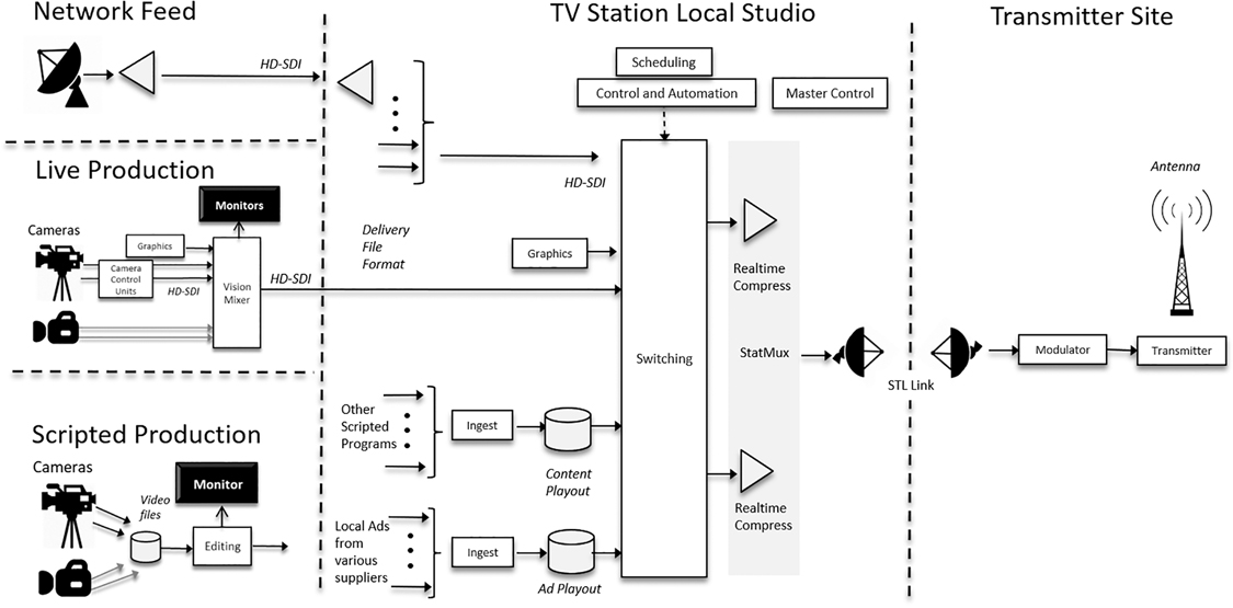
Figure 6.2 TV Station Content Workflow
History and Evolution of Cable Systems and Cable Channels
Cable television began to emerge as early as the 1960s, as a means of receiving broadcast television signals in areas with poor signal reception conditions. In such situations, a Community Antenna Television (CATV) often consisted of a tall TV antenna, with amplifiers driving the received broadcast signal over coaxial cable to homes in the community. Early cable systems provided better signal reception and picture quality than might otherwise be available to a consumer with a home antenna. Cable systems proliferated and their capacity to carry many channels of video also grew, as cable and amplifier quality (low-noise) and bandwidth capability advanced.
Cable systems eventually began to have more than enough capacity to carry all of the local broadcast television signals. The excess capacity was filled with the advent of specialized “cable channels” (e.g., HBO, MTV, etc.). Early cable channels used C-band analog satellite distribution to the many individual cable system operators’ headends. The cable systems themselves used the same transmitted signal format as broadcast signals, modulated to a different Radio Frequency (RF) channel on the cable. “Cable-ready” televisions provided the extended tuning capability and the coaxial “F-connector” that made consumer adoption of cable television simple and convenient.
As the cable industry expanded, consolidations began to occur. Companies that operated systems in different communities became referred to as Multiple System Operators (MSOs). The demand for channel capacity continued to increase as many cable channels continued to find audiences and provide unique content niches. Technology advances resulted in the development of Hybrid Fiber Coax (HFC) systems. The use of fiber links to local neighborhood nodes reduced the number of cascaded amplifiers and allowed further increases in capacity. By the early 1990s, many cable systems had between 350 and 500 MHz bandwidth, providing some 50–80 channels of analog television. Cable systems became increasingly sophisticated and the insertion of local advertising into cable channels became an established business. The initial technology relied on “cue tones” carried in the audio to trigger an insertion event. Eventually, this also became possible for the replacement of ads in local broadcast signals as well.
In the late 1990s, the digital television technology that revolutionized broadcast was poised to similarly impact cable television, particularly since industry representative had participated directly in the testing and evaluation of the Grand Alliance digital HDTV that was the basis for the ATSC broadcast standard. The same MPEG-2 digital video compression and transport was directly applicable to cable. However, the Vestigial Sideband (VSB) modulation and transmission approach that has some broadcast-specific innovations was not necessary for cable. Its very closely related and more traditional Quadrature Amplitude Modulation (QAM) was found to be suitable for a 6 MHz RF channel on a cable system. Digital standard definition cable channels significantly improved cable picture and sound quality and became widely deployed by the cable industry in the US in the early 2000s. At that time, a typical cable system had its “analog tier” in the lower frequency range of 6 MHz RF channels (e.g. 350 MHz and below) and its “digital tier” of QAM signals at higher frequencies. This approach allowed cable operators to continue their legacy analog services with no disruption to viewers, while launching the new tier of digital services as a premium service.
The advent of digital channels on cable was also inherently a catalyst for the advent of on-demand content. The earliest Video On Demand (VOD) approaches located video playout servers in proximity to a QAM modulator and assigned the requested content stream to a vacant QAM channel. This approach was costly to scale, since it required many replicated video server systems.
At the same time, the large data capacity of QAM digital video channels was apparent and Internet use was growing rapidly. CableLabs developed techniques for upstream data transmission on cable systems and produced the first Data Over Cable Service Interface Specification (DOCSIS) “cable modem” spec in 1997. Early DOCSIS cable modems could deliver 40 Mbps data speeds with a 6 MHz QAM signal. The deployment of DOCSIS cable modems drove an overhaul of cable for upstream communications, wider bandwidth downstream capability and the deployment of Hybrid Fiber Coax (HFC) architectures that use high capacity fiber delivery to local neighborhood nodes (typically 200–500 homes) and then convert to traditional coax cable for the “last mile” delivery to the home.
By the mid-2000s, subsequent versions of DOCSIS brought higher upstream data speeds, enabled voice-over-IP (VOIP) capabilities, and introduced IP v6 support. The cable industry deployment enabled the “triple-play” of video, voice, and data services. At that point a cable system consisted of three “tiers” of 6 MHz channels – the legacy analog television tier, a digital television QAM tier that delivered both HD and SD video programming, and a DOCSIS tier that carried digital telephony and Internet data. Cable operators served their set-top boxes with video services and provided gateway devices (i.e., DOCSIS modems) that provided Internet and telephone services. As WiFi became ubiquitous in consumer PCs, tablets, and smart phones, cable gateways provided the connection to the Internet and the WiFi hub for the home. In 2006, DOCSIS 3.0 provided “channel bonding” capability that could logically combine multiple downstream QAM channels to multiply downstream data speeds, achieving up to 1 Gbps downstream data speeds.
In 2013, the DOCSIS 3.1 spec allowed for different downstream data channel bandwidths, finally separating cable data transmission from the original 6 MHZ analog video channelization of the 1942 NTSC standard. With DOCSIS 3.1, 10 Gbps downstream speeds could be theoretically achieved. Throughout the 2010s, cable data service speeds continued to grow and become more widely available to consumers and businesses. Most recently, the 2017 DOCSIS 4.0 spec now allows fully symmetric data speeds and it is just beginning commercial deployments.
Traditional Cable Systems and Cable Channels
Before we progress to a description of modern cable systems and their Internet and video streaming capabilities, it will be illustrative to examine a “traditional” cable plant that simply delivers linear television channels. This would be typical of a cable system in the mid-2000s.
Figure 6.3 provides a very simplified high-level view of the end-to-end content ecosystem for the case of live linear channels. The Figure is intended to provide a high-level reference for discussing the functionality of the programmer and cable operator ecosystem; it is not representative of specific systems or architectures, which can differ among various content producers, programmers, and cable operators.
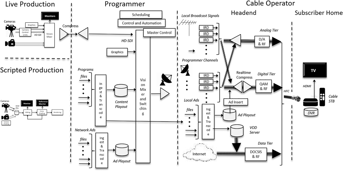
Figure 6.3 Traditional Cable/Linear Channels
Referring to Figure 6.3, on the ‘production’ side of content, it is important to understand that there are two categories of linear content creation and distribution – truly “live television” streams, which may include sports, special events, news and other content, and linear streams which are a compilation of pre-recorded content (a traditional linear television channel).
The linear television signals that cable operators deliver to their subscribers come from many sources, including cable Programmers, Broadcast Network’s local TV Station Affiliates and independent local broadcast TV stations, and operator-produced programming such as sports and news. These feeds may be in HD (16:9 1080i or 720p) and/or SD (4:3 480i) formats, which are delivered to consumers on different “tiers” of the cable system, which may include analog, digital standard definition, and digital high definition. These tiers require different consumer equipment and cable Set-Top Boxes. As of this writing, the analog video tier on cable is quickly disappearing, although it persists in many small systems in the US and internationally in emerging economies. And although virtually all modern TV displays are HD, many secondary cable STBs are still only SD-capable, pending their slow but inevitable replacement by HD boxes. Thus, for the foreseeable future, programmers and content owners must deliver content to cable operators in both HD and SD formats, or allow them to down-convert HD to SD using Active Format Description (AFD) metadata.
Referring again to Figure 6.3, as a live production signal is fed to a Cable Programmer, advertisements are inserted at appropriate points during the event. This is accomplished by ad playout servers and the same live signal interfaces that are used in production. Therefore, current operational practice is constrained to require that the ad inventory use the identical video format to the live production. Programmers may also insert graphics elements “downstream” from the actual production, often including channel branding logos and promotional animated graphic elements. Programmers then distribute their fully integrated linear signal to cable operators and other distributors, often applying video compression during this step.
Cable Operators receive linear channel feeds from many different Programmers. In addition, cable operators re-transmit local TV broadcast stations. In many larger markets, a direct fiber connection is available between TV stations and cable ingest points. However, many markets continue to rely on direct reception of broadcasters’ over-the-air signals as the source for re-transmission.
Cable operators also have a significant business in ad insertion for both Programmer and Broadcast channels, since they can perform geographic and/or demographically targeted ad insertion. Advertising segments used by cable operators come from a wide variety of national and local sources. Cable operators’ ad insertion systems and ad inventories must deal with the variety of source signals and video formats (e.g., HD 1080i, HD 720p, SD that are distributed by various Programmers and Broadcasters). Moreover, cable operators must be able to insert advertising in linear channels, “start-over” playback, DVR playback, and on-demand viewing. The technical quality, complexity, and latency must meet both operational and business agreement needs. Note that the adoption of multiple formats affects the implementation scale in terms of transmission and storage (including ads).
In the case of delivery to a cable-operator controlled set-top box (STB), video compression at the headend and decompression in the STB are controlled by the cable operator, as are the insertion of navigational and closed caption graphics. The consistency and visual quality of navigation functions (e.g., picture-in-picture, multi-channel mosaic screens, etc.) and graphics across various programming channels are important requirements for providing a high-quality user interface and navigation experience to subscribers.
Cable STBs connect to modern TVs with the digital HDMI interface. Although analog interfaces still exist in legacy STBs and old TVs, typically only HDMI with content protection such as HDCP (High Definition Content Protection) is used for HD content. The video format of an HDMI connection is determined by a special “handshake,” during which no video data is transferred. The viewer disruption associated with an HDMI format switch has resulted in current practice being to have the STB output a single video format to the TV. This means that regardless of the actual transmission format, resolution conversions are often performed by the STB hardware.
History and Evolution of Satellite Television
Even as cable television adoption grew, the capability to distribute television over a large geographic footprint was an opportunity that was potentially well-suited for satellite television distribution. For a time in the 1980s and 90s, an illegal market for large backyard C-Band receive dishes existed. Consumers with a large dish could (illegally) receive the cable channels that were being sent to cable headend without paying to receive the services. This started a cycle of applying analog scrambling techniques to make the signals non-standard, but black-market descramblers became readily available. By the late 1980s, this situation started to motivate the conversion of cable channel programming to cable headends to move to a digital format, where digital encryption could be applied as a strong content protection measure.
In the early 1980s, much work was underway around the world to explore the opportunities of direct-to-home (DTH) satellite television. High power satellites were being developed, which would help to reduce the size of consumer receive dishes to practical sizes for use in typical homes. The World Radio Conference designed frequencies and orbital slots for Direct Satellite Broadcasting (DBS).
Attempts were also made to improve the quality of television delivered over satellite, so analog component signals (Multiplexed Analog Components) were defined that eliminated some of the artifacts of composite video signals (e.g., NTSC and PAL). Although they had some limited commercial success in some areas of the world, analog satellite systems had far less capacity (typically 24 channels) than satellite and were more costly for both operators and consumers.
After the four digital systems had emerged in the US race for digital HDTV, it became apparent that the same technology could be applied to satellite television. With the efficiencies of digital compression and the robustness of digital transmission, satellites could deliver amounts of programming that was on par with cable systems of the time. DirecTV was formed and launched the world’s first Digital Satellite System in 1995, using MPEG-2 compression and the proprietary data packet format of the Advanced Digital HDTV system. Satellite set-top boxes quickly incorporated disc storage for Digital Video Recorder (DVR) consumer recording and to provide Video On Demand Services. Popular VOD movies are highly compressed and sent as data files to the DVR disk, which serves as a data cache for on-demand content. Able to provide pay-TV services to rural areas of the US that were not reached by cable, adoption grew rapidly (at the time, it was the fastest-adopted consumer product in history; only later surpassed by DVD). DISH Network followed suit and as of this writing, the two satellite services reach over 25M subscriber households in the US.
DTH (Direct To Home) satellite television systems have continued to advance their digital technology base since their initial launch with MPEG-2 compression and standard definition video. In the early 2000s, DirecTV began offering HDTV services, which shocked the US cable industry, where many thought that digital standard definition would satisfy consumers. DTH satellite systems migrated to the next-generation MPEG-4 codec and high-definition video and are currently in the process of introducing the H.265 codec and Ultra High Definition (4K) video.
The DVB standards organization developed successive generations of standards for satellite television (DVB-S, DVB-S2, and DVB-S3), which helped to catalyze the launch of DBS systems around the world. As of this writing Satellite TV is a widely adopted distribution technology in most areas of the world.
As broadband Internet connectivity became increasingly common, satellite STBs incorporated Ethernet and WiFi connectivity, enabling operators to provide content via over-the-top streaming in addition to linear video channels on the satellite and locally cached content.
Modern Satellite Television Systems
Today, a typical DTH satellite system is often a hybrid of satellite and over-the-top infrastructure. The satellite system operator gathers its many channels of linear programming from a combination of C-band and KU-band satellite receive dishes and IRDs (the same satellites, transponders, and signal that also serve cable operators) and direct fiber connections to large media companies’ distribution centers.
In areas where local TV station signals are retransmitted on pay-TV satellite systems, the local station’s signal is either directly fiber connected to the DBS operator, or alternatively, all of the stations are received from an over-the-air antenna and connected to the DBS operator on a fiber. At the satellite system operator’s Network Control Center, the video feeds are converted to baseband signals, and efficiently compressed into satellite transponder sized multiplexes, using Statistical multiplexing.
History and Evolution of Internet Video and OTT Services
Internet Protocols (TCP/IP) were invented in the 1960s and became widely used to interconnect large computers in academia and industry. The advent of personal computers created an environment for dial-up modems to connect them to “Bulletin-board” services where they could interact and share information among users in simple ASCII text format. Early bulletin board services like CompuServe and AOL were launched in the mid-1980s. The IBM PC and Microsoft DOS sparked the introduction of PCs into the corporate world, driven by applications such as word processing and spreadsheets. Local area networks (Ethernet) enabled corporate PCs to share files and utilize email and Internet connections bridged corporate campuses, and interconnected with academic computing centers. Graphic User Interfaces (GUIs), windows, and the mouse were inventions of the late 1990s that greatly increased the usability of personal computers.
By the early 1990s, Digital HDTV system developments were already underway when HTTP and the browser were invented. The Grand Alliance HDTV system was nearing completion when Windows 95 was released and brought the windows and mouse innovations to PC users. Even as digital HDTV was on the verge of launch, there was debate about the future roles of televisions and computers; phones were analog and 1G analog cell phones were the size of a shoebox. Consumer Internet access was predominantly dial-up modems, which had increased in speed from 1.2 kbps to subsequent 2.4, 4.8, 9.6, and 19.2 kbps generations. Modems over telephone lines were reaching a fundamental limitation in performance, but higher speeds were becoming a necessity as relatively data-hungry HTML pages began to be consumed by browsers. The innovation of Digital Subscriber Lines (DSL) from phone companies enabled higher speeds and direct connection to an Internet “home page,” but they were expensive and only available in limited geographic areas. Nevertheless, pioneering developers began to experiment with video delivery on the Internet. While quality was significantly poorer than standard definition video that was available on cable and satellite, the integration of video content on web pages began.
As described in the previous section, the growing deployment and adoption of Cable Modems (DOCSIS) in the early 2000s brought high-speed Internet connectivity to a rapidly growing number of homes. With higher data speeds, the quality of video increased commensurately and the opportunities for video content delivery on the Internet became more apparent. Notably, YouTube was founded in 2005 and was quickly acquired by Google in 2006.
Unlike web pages and data files, the delivery of video requires a consistent “stream” of data to be delivered. Internet Protocols were not designed for such an application, being inherently a “best effort” approach to communications over a network. The quality of streaming video delivery was significantly advanced by three technical innovations. First, Content Delivery Networks (CDNs) were invented to cache Internet content assets at the “edge” of the Internet cloud, geographically closer and fewer network communication hops to users. CDNs accelerated the delivery of all web page content assets, but they were crucial to achieving video streams. Second, the concept of Adaptive Streaming is that there can be multiple representations of a piece of content stored as different files having different resolutions and data rates. If the nominal data rate of a video stream cannot be maintained, the video player can temporarily access a lower quality, lower bit rate version of the content. This is important at the start of content playback, in order to reduce long wait times while the decode buffer is initially being filled (i.e., the familiar “buffering” message”), as well as to avoid the stream totally freezing due to intermittent network congestion. Third, the development of HTML5 (the latest version of web page standards) provides for a <video> tag, in which video elements are easily represented on web pages. Furthermore, its Encrypted Media Extensions (EME) allow for content encryption and protection by Digital Rights Management (DRM) systems, enabling pay-TV subscription models. While proprietary DRM systems existed since the 1990s, their seamless integration into the web was significantly advanced by HTML5.
Although it was initially launched as several proprietary, non-compatible approaches, adaptive streaming technology has matured and become more standardized. Dynamic Adaptive Streaming over HTTP (DASH) is a standard developed in the MPEG group and it is gaining widespread adoption. However, Apple continues to support their HTTP Live Streaming (HLS). As of this writing, DASH and HLS are the two most common video streaming protocols.
Similarly, encryption and DRM systems for content protection began as highly proprietary systems. The approach of Common Encryption (CENC) has been standardized and it allows the use of multiple DRM systems to protect content. As of this writing, Google Widevine, Microsoft PlayReady, and Apple Fairplay are among the DRM systems that are in widespread use.
In fact, seeking compatibility with Internet video standards, the new ATSC 3.0 broadcast standard makes use of HTML5, DRM systems, and common encryption Internet standards.
Thus, using the streaming video standards of the modern Internet and the high data speeds of DOCSIS cable modems, video content can be delivered “over-the-top” of traditional cable systems and their legacy video-centric technical standards.
Modern Internet Video and OTT Services
Today there are many Over-the-Top (OTT) video services available as either subscriptions or ad-supported content. These services can be accessed via a web browser, but the proliferation of smart phones, tablets, smart TVs, and streaming video set-top-boxes has given rise to service-specific “Apps” (applications) for those devices. Most OTT services provide on-demand content, but live channels are increasingly becoming available on some services (Figure 6.4).
An OTT service operator ingests content and applies video compression encoding to produce multiple resolution and quality levels for its adaptive streaming “stack” of versions that are most appropriate for different connection bitrates. Additional versions may be performed to support different video codecs that are supported by various consumer devices. At the same time, the video is broken into short segments of a fixed time duration, typically in the range of 2–10 seconds. Each of these segments is a file. The video data for a given piece of content is thus a large collection of files that are all of the segments for all of the adaptive bit rate stack, which is represented by a master Manifest file.
The complete set of files for each piece of content is published on an “origin server.” From there, copies are propagated throughout one or more CDN systems, so that the data resides in close physical and connection proximity to users.
When a user App (or web browser) requests a piece of content, the OTT service’s web server determines the user device’s capabilities, supported protocols, and DRMs and the best video resolution and codec that is supported by the device. A session-specific Manifest is created that contains the nearest CDN cache’s URLs (i.e., file names) of each ABR representation for each time segment is built and sent to the App. Content playback occurs by the App requesting each successive segment of content from the CDN. As the data is retrieved from storage a “Packager” wraps the compressed video data in the appropriate protocol (e.g., DASH or HLS) and provides the decryption keys for the appropriate DRM system.
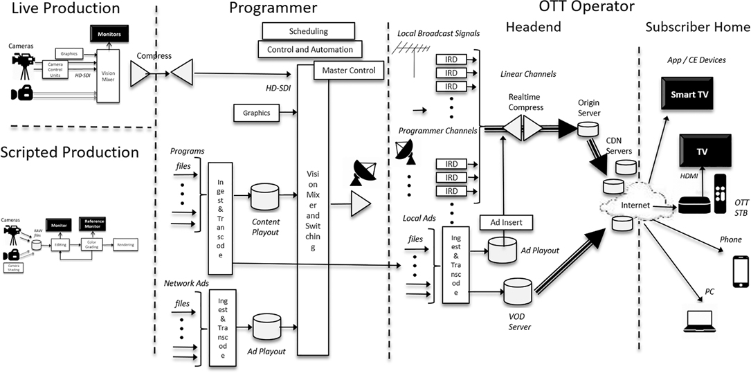
Figure 6.4 OTT Content Workflow
At the user device, the requested data fills a buffer and is subsequently decompressed into a baseband video representation for display on the device. The App monitors the buffer state and if it is too low, it indicates that the Internet data rate cannot keep up with the video decoding rate. In such a situation, the App will examine the Manifest file and request its next segment from a lower level of the ABR stack. By continually monitoring the device’s buffer state, the App can “downshift” to a lower quality / lower bitrate representation during temporary period of network congestion and “upshift” back to a higher quality / higher bitrate representation as the Internet connection speed improves.
Digital ad insertion (DAI) for targeted advertising is one of the capabilities of OTT that is often utilized. The simplest OTT systems create the Manifest with URLs for the desired ads, which are retrieved by the App (client software) in the course of content playback. More sophisticated handshakes are used to trigger an event at a commercial break, at which time the App queries an Ad Decision Server to get the URLs of the target ad, content, which are retried by the App. This approach is referred to as “client-side ad insertion.” Alternatively, OTT systems increasingly employ “server side ad insertion,” where the CDN issues a new manifest to the App.
Modern Cable Systems
Modern cable systems are an amalgamation of traditional cable and OTT architectures. In addition to live linear transmission and on-demand content, cable operators usually provide DVR, “cloud DVR,” and “start-over viewing” functionality to subscribers. Modern cable systems deliver traditional TV services to operator-controlled set-top-boxes (STBs) and “TV Everywhere” services to Internet-connected consumer devices with an operator App. Many cable system operators acknowledge that they are beginning a transition to an all IP network and operations infrastructure. In support of this, many cable STBs contain traditional MPEG-2 video and QAM modulation decoding as well as a DOCSIS modem and support for additional video codecs and protocols used in OTT streaming. This will enable the migration of on-demand, cloud DVR, and startover services from cable-industry-specific systems to solutions that are based on commodity IP and Internet hardware and software for streaming video. However, it is important to understand that the details of network utilization, STB software, and the level of support for streaming video delivery to various consumer devices to vary widely among cable operators.
Today, the digital content and ad files delivered to cable operators are transcoded to the specific formats required by their client STBs to receive cable on-demand and OTT on-demand video streams.
In addition, many on-demand services require the insertion of advertising segments, which similarly come from a wide variety of sources. These on-demand systems and the insertion of advertising require that the same video format is maintained across the content and the ad.
The considerations involving consumer devices and interfaces are essentially the same regardless of whether linear or on-demand content is being delivered to a subscriber.
History and Evolution of Pre-Recorded Media
With the emergence of consumer video tape cassette recorders in the late 1970s, pre-recorded cassettes of movies became immensely popular for consumer rental and purchase. A protracted “format war” was waged between BetaMax and VHS formats, with VHS being the ultimate commercial winner. The analog tape standards were lower quality than analog broadcast and cable delivery, but the convenient availability of content was new and compelling for consumers.
During the 1980s, technologies for higher-quality pre-recorded analog discs were developed using both capacitive and laser playback technologies. The formats did not achieve widespread consumer adoption, but they paved the way for the next generation of digital technology that would come in the 1990s.
Following the development of digital television in the early 1990s and virtually in parallel with the commercial development of digital satellite television, the pre-recorded digital optical disc DVD (Digital Versatile Disc) standard was also enabled by MPEG-2 video compression and advances in optical recording density, which could store approximately 8.5 GBytes on the same 12 cm disc form factor as audio CDs. The use of multiple layers can be used to further increase storage capacity.
DVD was launched in the mid-1990s. Before commercialization, competing factions came together to avoid another ‘format war” and DVD was a huge success that enjoyed rapid consumer adoption (at the time it was the most quickly adopted consumer product in history). Despite its age and technical obsolescence, DVD distribution still remains in the media landscape today.
The DVD format provided conventional 4:3 aspect ratio or widescreen 16:9 standard definition digital video, along with 5.1 channel surround sound, closed captions, and subtitle capabilities. With MPEG-2 video compression at typical bit rates of about 6 Mbps for 480p24 (film) and 480i (video) formats and Dolby Digital and other surround soundtracks, DVDs provided consumers with a huge leap in the picture and sound quality and convenience of pre-recorded content. It had a simple menu system that enabled chapters for simple consumer navigation of content. Many movie DVDs contain bonus features and extras to help entice consumer purchase of the content. Specialized DVD authoring tools are required to create discs, which were initially manufactured only in large optical disc pressing plants. The advent of recordable and re-writable DVD discs (+R, –R, and –RW formats) unleashed the potential for consumers to easily edit and create their own home videos using a camcorder and a personal computer.
By the mid-2000s, HDTV adoption was growing, and it became obvious that a successor optical format would be needed for HDTV content. By the early 2000s, an industry “format war” erupted between the competing HD-DVD and Blu-ray formats, which were launched commercially in the mid-2000s. Although Blu-ray eventually emerged as the winning format, the protracted industry battles and consumer confusion delayed the adoption of the format so that it quickly became challenged by emerging downloadable digital file formats and online/on-demand streaming delivery.
The Blu-ray Disc (BD) format uses the AVC/H.264 video compression standard (the successor to MPEG-2) and a blue laser that achieves higher data storage density – approximately 25 GBytes of data on the same size 12 cm disc as a DVD. Single, dual, three-, and four-layer discs are available. With these storage densities and the advances of AVC/H.264 video compression and advanced audio codecs, the Blu-ray format provides outstanding HDTV (1080p24 film and 1080i or 720p video formats) picture and surround sound quality to consumers. Like DVD, Blu-ray has menus and use navigation software framework, which in its technical details is based on the Java programming language that is much more modern than its primitive DVD predecessor.
The BD format has been upgraded and evolved to include 3D video and “Mastered in 4K” video that is delivered in 1080p format on the disc. In 2015, the UltraHD Blu-ray format was launched, which is capable of UHD (4K) video playback in both standard and High Dynamic Range formats and advanced immersive audio (object-based sound) capabilities. UltraHD Blu-ray players also support conventional Blu-ray and DVD playback.
Although UltraHD Blu-ray arguably provides the best-available video and audio quality for consumers, many industry observers speculate that it may be the last physical media format, being eclipsed by the convenience of online on-demand video streaming. Nevertheless, in the immediately foreseeable future UltraHD Bluray, Blu-ray, and DVD discs remain part of the media delivery landscape.
History and Evolution of Digital Cinema
At the time when the development of digital HDTV for US broadcasting was progressing in the mid-1990s, cinemas continued to rely on the distribution of 35mm film and the use of film projectors in theaters. Several early attempts to apply digital HDTV technology to the cinema ecosystem were commercially unsuccessful but created an industry awareness of digital compression and file delivery technologies.
Digital Cinema Initiatives (DCI), LLC, a joint venture of the major film-making studios, was formed in March of 2002 with an objective of establishing voluntary specifications for digital cinema. A key goal was that the image and audio would minimally be equivalent to or better than a 35mm film print. Significant testing was accomplished and the first Digital Cinema System Specification (DCSS) was first published on July 20, 2005.2 This was followed by the DCSS Compliance Test Plan on October 16, 2007, which was used by manufacturers to demonstrate compliance with the specification. While equivalent to or better than a 35mm film print, this effort brought about two other major advantages for the movie-going public: each presentation provided clean images, since there were no longer film prints gathering dust and getting scratched with each passage of film through the mechanical system of a film projector, and each presentation was steady, since there was no film print weaving/juddering through the mechanical system of a film projector. The changeover of film projectors to digital projectors began in earnest around 2005–2006, and by 2013 had occupied well over 90% of the commercial market in the United States.3 Today, film projectors occupy only about 0.5% of the US market.
The DCI DCSS was adopted by and developed into approximately 50 fully detailed standards, recommended practices, and engineering guidelines by the Society of Motion Picture and Television Engineers (SMPTE).4 All the key SMPTE standards needed for program interchange were later adopted and published by the International Standards Organization (ISO). The following sections will discuss the current state of these standards for distribution of D-Cinema content to movie theaters and will discuss the workflows and distribution architectures for both movie content and other live content to movie theaters. Figure 6.55 is the Digital Cinema System Workflow as currently presented in the DCI DCSS. The left green boxes describe the mastering of 2K or 4K movies and all the other assets as discussed earlier in this book. The turquoise blocks refer to the steps of creating the package, known as the Digital Cinema Package (DCP) that will be sent to theaters. The blue blocks refer to the distribution of those DCPs to theaters. The yellow storage container refers to the theater storage system. The red arrows clarify that 4K movies can be played out by either a 2K or 4K projection system as shown by the boxes on the right. These items will be covered in more depth in the following sections.

Figure 6.5 DCI Digital Cinema System Workflow
Modern Digital Cinema Workflows
The distribution of digital cinema content is unique from other forms of audio-video content in that the picture is not bound to the sound for distribution. Instead, a DCP is delivered to each movie projector that minimally contains two .mxf “track files” of picture and audio, and may optionally contain additional track files of subtitles, captions, etc., which the projector will select and render at show time based upon a unique Composition Play List (CPL) for that show. This way, a single DCP package can be distributed to many movie theaters, and each projector will select the files appropriate for that showing, and play all the appropriate pieces based upon the instructions in the CPL. This not only streamlines the distribution process by allowing all components to go to all theaters, but also provides more flexibility for the theater to customize their presentations to their audiences. As an example, a Paris theater showing a popular English PG film may play a version of the film that is dubbed in French for their matinee shows where young children who do not read may be present. But in their later evening hours, they may show the native English soundtrack and display French subtitles for an older audience.
Previous sections of this book have described the post-production aspects of creating the raw essence components that are needed for a movie presentation. Picking up from there, the following sections will describe the workflow shown in Figure 6.5. One item of note with respect to the raw assets is that while the bulk of the work is done in post-production to create the basic image and audio assets, more and more of the work done for “localization” has been pushed out from the post houses to the distribution houses. Previous chapters of this book have addressed the main localization items of dubbing in foreign languages, subtitling in the local language when a foreign language is being spoken in the movie, and closed captions in the local language for the hearing impaired. But there are also other miscellaneous localization tasks that need to be performed as well. Common to all films is converting the main opening movie titles and the credits into local languages. Another item that arises frequently is when an image with words appears in the film that needs to be localized to the country. As an example, imagine a children’s animated film that has a STOP sign for the English-speaking markets. Using Computer-Generated Imagery (CGI), the word STOP will be changed to the appropriate signage word for each country.
Mastering
Mastering, as shown in the green boxes on the left of Figure 6.5, is the step of preparing the raw assets for distribution. In the following sections, the various track files, also known as “essence assets,” which need to be prepared for the DCP, will be explained: Picture, Stereo (3-dimensional 3D) Picture, Sound, Immersive Audio, Captions and Subtitles, and Auxiliary Data. And there are always exceptions to the rules, captured in the Other Unique Formats section.
Picture
A picture track file must be included in a DCP. As mentioned earlier in the book, the aspect ratio (AR) of most movies are “flat” with an AR of 1.85:1 or “scope” with an AR of 2.39:1. Recognizing that theaters may also want to present modern television content, particularly for a pre-recorded live event, the modern HDTV AR of 16:9 or 1.78:1 was taken into consideration. DCI established a picture “container” of 2048 pixels wide by 1080 high for a 2K distribution and 4096×2160 for a 4K distribution, in which all these ARs could be handled. From these specifications, a scope 2K movie will use 2048 pixels wide by 858 high and a flat 2K movie will use 1998 pixels wide by 1080 pixels high ratio.
After significant testing, DCI selected JPEG20006 for picture compression at a maximum bit rate of 250 megabits per second (Mbps). It was recognized that both 2K chip sets and 4K chip sets would be used in projectors. The JPEG2000 compression permits a very high-quality 2K image to be displayed by a 2K chip set without having to decompress the 4K layer. This is an important and inherent characteristic of the wavelet compression approach used in JPEG2000. This means that the same image file is sent to all theaters, and whether a given screening room has a 2K projector or a 4K projector, the same file is able to be processed by all projectors as shown in Figure 6.5.
The picture track file is created by compressing the Digital Cinema Distribution Master (DCDM) described in the postproduction section of this book into JPEG2000 images at 250mbps, which generally results in about a 10:1 reduction in file size. Preprocessed forensic marking can be added if desired. The picture track file is typically specified to run at 24 frames per second (FPS). Within the standards, there are also provisions to specify playout at 25 FPS (sometimes used in Europe), 30 FPS (sometimes used for TV content). The Picture essence assets are most always broken into several track files labeled as “reels.” The concept of reels stems from the days of actual film that had to be broken into many physical reels, each of which was roughly the same length containing 15–25 minutes of film, to be shipped to theaters. Today, the sizes of the reels vary widely, and are broken into segments that make sense to the production crew. Opening titles and end credits are often separate reels, and the main movie is typically broken into logical story segments. (Note that the segmentation may be chosen in anticipation of ‘chapter’ and menu structures that are often used in Blu-ray, DVD, and on-demand versions of the content.)
There is also a capability for picture branching. Using the previous example of an animated film with a stop sign that needs to be changed into a variety of languages, rather than replicating all the picture images in the whole movie, the DCP can include multiple copies of just the clip of frames that contains the stop sign, each copy having a different foreign language word for STOP. When the film is played out, the CPL instructs the projection system to branch out of the main picture, also known as the Original Version (OV) to the appropriate foreign version of the clip, and then branch back into the main picture. Again, this reduces the number of versions that need to be sent to all theaters in the world.
Stereo Picture
With the stability of the new digital projectors, coupled with advances in stereo viewing glasses, a resurgence of stereo presentations, or “3D movies,” was seen starting in just a few years after the release of the DCI DCSS. While peaking in 2010 with the release of Avatar, stereo presentations have maintained a presence between 10% and 15% of the US box office, mostly on blockbusters, horror, and children’s animated films.7 While holding a small niche spot in theatrical presentations, stereo presentations have not garnered favor in home viewing. It is believed that wearing 3D glasses in a home environment have been a barrier for most consumers.
For theatrical stereo presentations, the picture track file will contain interleaved images for the two eye perspectives. Frame 1 for the left eye will be followed by frame 1 for the right eye, followed by frame 2 for the left eye, followed by frame 2 for the right eye, and so on. Stereo presentations are most commonly specified at 48 FPS (because the projector must present 24 FPS for the left eye and 24 FPS for the right eye simultaneously). Fifty FPS is used for some European stereo presentations and 60 FPS for some television presentations.
Stereo track files for a movie are not carried in the same DCP as the 2-dimensional (2D) picture files for a movie. The reasons for this are several. As film companies have improved their stereo processes, the 3D version of a movie often has slightly different editorial cuts than the 2D version of the movie, and “floating windows” trim off sides of the images to improve human perception of the stereography. Thus, audio, subtitles, etc. used in the standard 2D version of the movie, cannot be simply duplicated for the 3D movie version. Another complicating factor is that stereoscopic movies are often color-corrected at several different brightness levels, with 3.5–4 foot-Lamberts (fL) being the most common, and additionally at 7 fL and 10 fL for movies with larger distribution. The reason for this is that stereoscopic viewing systems typically result in the human eye receiving 50%–75% less light than is seen for a 2D movie and, therefore, there is a wide range of maximum brightness available at theaters throughout the world. To offer the best possible experience on all of these screens, stereoscopic movies are color-corrected at these multiple brightness levels, and each of these becomes a separate DCP. This creates an inventory, logistics, and distribution burden to ensure the correct version gets to the correct theater.
Standard Sound, Immersive Audio, Foreign Language Dubs, and Descriptive Audio
At least one audio track file must be included in a DCP. The original DCI DCSS identified the use of both 5.1 and 7.1 surround mixes. Two channel, stereo presentations are not part of the specification. By far the most common format, the 5.1 surround mix, contains digital audio at 24-bit 48 kiloHertz (kHz), comprising six audio files. There are also provisions for a 7.1 surround mix at 24-bit 48 kHz, comprised of eight audio files, more commonly used on larger budget movies. Audio files are not compressed and are carried as linear Pulse Code Modulation (PCM) multichannel WAVeform (WAV) files.
In recent years, there have been several companies that have developed “immersive audio” for theaters, which has many loudspeakers positioned around and above the movie audience. For these mixes, up to 128 “slots” are allocated in an Immersive Audio Bitstream (IAB) for conveying any combination of channels and audio “objects.” This IAB is carried in an Auxiliary Data track file (see subsequent section on Auxiliary Data). The DCSS refers to the IAB as Object-Based Audio Essence (OBAE).
The transition from physical film to digital movies assembled by the projector allowed for many other advances, including the ability to carry many sound files. In the world of physical film, each movie theater in the world had to receive a copy of the film with the appropriate language audio track on the film. This required very careful inventory management and logistics management to ensure each theater had the right version. Because digitized audio is relatively small in comparison to the image files, a digital cinema package can include many dubbed audio files in many foreign languages. The actual file that is heard in the theater is determined by the CPL (see later section).
The transition from film to digital also provided easier access for people with some disabilities. A Hearing Impaired (HI) audio track is provided as a separate sound file, which boosts the dialogue and minimizes the music and sound effects to aid aging viewers with hearing loss. An audio description track is also included as a separate sound file for visually impaired (VI) audience members, which provides a narrated description of the action happening on the screen when there is no dialogue occurring. Consumers can hear these special tracks by using headsets available at the movie theater or by enabling accessibility applications on their Android or IOS devices. In late 2016, the United States (US) Justice Department issued a final ruling under title III of the Americans with Disabilities Act of 1990 (ADA) requiring all movie theaters to provide movie captioning (see next section) and audio description for all movies.8
Captions and Subtitles
Captions provide a written version of the spoken dialogue for viewers who are hearing impaired. Captions are occasionally offered as Open Captions, where the words are presented directly on the movie screen, particularly if a significant portion of the audience are hearing impaired. Closed Captions are more common, where consumers can see the captions presented on handsets available at the movie theater or by enabling accessibility applications on their Android or IOS devices. As noted above, this service was mandated to be available in all US movie theaters and was completely rolled out by June 2, 2018.
Unlike captions, which are in the same language as the dialogue, subtitles refer to a translation of the spoken dialogue into the native language of the viewing audience. These are displayed by the projector directly onto the screen along with the movie image. Subtitle tracks are extremely small files in comparison with the picture or the sound, so all subtitle tracks are routinely included in the DCP and the CPL determines which subtitle track is played with the movie.
Subtitle/Captions essence is generally structured as a timed-text .xml file that holds all the information about wording, size, color, location, and timing. One of two font style formats is needed; most commonly a TrueType Font (TTF) file defines the general font style to use for subtitles. Alternatively, and most often used for large character set languages, Portable Network Graphics (PNG) files can also be used.
Auxiliary Data
Auxiliary Data tracks were originally made available in the DCSS to help accommodate new technologies or processes not previously imagined, and are often used for such purposes on an on-going basis. As noted above, this has now become a standardized method for delivering immersive audio to theaters.
Other Unique Formats
While it would be most ideal if all the data for all movies worldwide could be carried in a single DCP, that is not practicable when it comes to multiple copies of the image file, which is very large. As a result, except for 2K and 4K resolution images – which are compressed into the same file – when different image files are required, they are most often placed into separate DCPs. There are several scenarios for which this occurs, and all of these create an inventory, logistics, and distribution burden.
There are provisions for standard 2D movies to be presented at 48 FPS, 50 FPS, 60 FPS, and 120 FPS for high frame rate (HFR) presentations. Billy Lynn’s Long Halftime Walk was exhibited in 2D at 120 FPS in selected theaters. For stereo HFR presentations, the first three of these rates can be doubled to 96, 100, or 120 FPS respectively in order to present each eye with an HFR sequence of images. These files are compressed at 500 mbps (250 for each eye). The Hobbit trilogy was presented in 3D at 48 FPS for each eye (96 FPS) and Billy Lynn’s Long Halftime Walk was presented at 60 FPS for each eye (120 FPS).
More recently, we are seeing the emergence of High Dynamic Range (HDR) content being presented in movie theaters. Because of the increased color volume available for these projection devices from the traditional movie projectors, a separate color-correction is created for these HDR-capable systems and is placed in a separate DCP.
There are some extraordinary presentations in some theaters that are not carried in the DCP, but instead are synchronized with the movie playout by using an output of SMPTE 12M Time Code from the projection system. Examples of this are some side screens, motion-based seats, lighting effects, and other atmospheric effects.
Creating the Digital Cinema Package (DCP)
MXF Wrapping and Encryption
Now moving to the turquoise boxes of Figure 6.5, the mastering track files are all wrapped using the Material eXchange Format (MXF). All image frames for a reel are wrapped into one video .mxf file. For a typical 20-minute reel of a 2D 24FPS movie, these files are often over 20 GigaBytes (GB) in size. All the audio channel WAV files (standard audio mix plus HI and VI) for a reel are wrapped into an audio .mxf file, creating a file that is about 1–2 GB in size. Likewise, the captions and subtitles are individually wrapped for each reel, resulting in files that are under 10 MegaBytes (MB) (PNGs being images will be larger than time-text). All total, most movies typically end up with a package in the range of 200–300 GB.
While encryption is voluntary, virtually all picture, audio, subtitles, and closed captions are encrypted using the 128-bit Advanced Encryption Standard (AES) using the Cipher Block Chaining (CBC) mode and using symmetric keys.
Composition Play List (CPL)
The Composition Play List (CPL) is uniquely created for each theatrical movie order and ties everything in the DCP together for a successful movie presentation. Well before a movie is scheduled to play, the Theater Management System (TMS) at a multiplex, or an individual projector system at a single theater, will read the CPL to determine whether all the specified components are available for the movie. The CPL contains a written human description of the movie in a field called the Content Title Text for use by theater managers/projectionists. Because early digital projection systems had limited space to display this field, the Digital Cinema Naming Convention (DCNC)9 was developed by the International Society Digital Cinema Forum (ISDCF), which is still used today worldwide for the Content Title Text field. Later, at movie time, the CPL contains all the information needed for the movie playout. Just before playout, vital projector settings, such as whether the movie is 2D/3D, 2K/4K, flat/scope, FPS playout rate, 5.1/7.1 audio, etc. are provided to the projector. Then the CPL orchestrates all the appropriate essence assets together, turning what is otherwise just a random set of encrypted image, audio, subtitles, and auxiliary assets into a synchronized feature composition. The CPL breaks down the playout of the composition by reel. For each reel, the CPL defines which image .mxf, audio .mxf, and other optional essence .mxfs will be played out in synchrony. The projection system will read the CPL and pull all the specified tracks to render the presentation.
Asset Map, Volume Index, and Packing List
Once the essence mxfs and their orchestrating CPL are generated, the only thing left to do is to package those assets for delivery to a theater. This is where the Asset Map, Volume Index, and PacKing List (PKL) come into play.
All files within a DCP are referenced by a Unique Universal Identifier (UUID) rather than by file name. The Asset Map is the high-level control file type in the DCP, listing all assets within the DCP (expect for the volume index) and associating those assets UUIDs to their file path and name in relation to the location of the Asset Map.
Volume Index is a legacy file type used to break up a DCP over multiple storage volumes. When hard disk drives (HDD) were still expensive, this feature allowed breaking up a movie DCP over multiple storage devices, such as DVDs. The volume index was a simple tool used to track how many volumes (storage devices) were needed to complete the set.
Finally, with so much data contained within a DCP being transferred to theaters around the world, a method for describing what is in each delivery and for validating the content arrived intact was needed. The Packing list resolves this by listing all the files of a DCP (expect Asset Map and Volume Index) and associating them with a file hash. The Secure Hash Algorithm (SHA) 1 is used to ensure that a DCP arrived at the theater with no bit level file corruption errors. The Packing List (PKL) also describes the contents of the DCP sent in this transmission. It is possible, though not common, to send DCPs that are partially filled and to send additional components in a second shipment. As an example, this can be helpful if different track files are being produced in different parts of the world. It is also possible to send updated elements in a later shipment. For example, an updated reel of the end credits could be sent along with a new CPL without having to resend all the other picture reel tracks, audio tracks, subtitle tracks, etc.
Key Delivery Message (KDM)
The Key Delivery Message (KDM) carries important security information and ensures the movie is only played on authorized equipment. A valid play “window” is provided, listing a start day/time and a stop day/time. Real-time watermarking, while optional, is almost always indicated as being required in the KDM. This security information, and all the symmetric keys that were used to encrypt the assets are then encrypted using asymmetric 2048-bit Rivest–Shamir–Adleman (RSA) public/private pairs to create a unique Key Delivery Message (KDM) for each projection system that has been authorized to play the movie. At playout time, the projection system must be authenticated in order for the KDM to release the encrypted files to be played. Because of this public/private key encryption technique, the KDMs can be transmitted to the theater by any means without worry of being confiscated or misused.
Transport
The big blue arrows shown in Figure 6.5 relate to the methods by which the DCP gets to the movie theater. From the introduction of digital cinema as a global distribution standard for theaters, physical delivery of DCPs has been the norm. Feature DCPs, generally ranging from 200 to 300 GB easily fit onto common, relatively inexpensive, 1 TeraByte (TB) hard drives. And while freight must be factored into the equation, physical delivery allows for quick and exact scaling to meet the month by month distribution needs for all motion picture studios, both small and large. Alternatively, for distribution of smaller packages like trailer DCPs, USB thumb sticks are a common option. Independent of the physical media, storage technology, form factor, or connection specification; the industry has generally landed on using an EXTended (EXT) file system format of either EXT2 or EXT3. For mass duplication, methodology can vary, but often high-speed block-by-block duplication is used to copy content from a master drive to multiple slave drives at once. Validation methods can also vary, either using block scan to compare the master drive to slaves or utilizing the built in SHA1 checksums with a DCP to re-validate content after duplication.
Of course, with DCPs being a file-based format, electronic delivery is also an option and has become common across most regions of the world. Most electronic delivery networks consist of a digital transport path and edge device at the theater that receives and stores the DCP before handing it off to Theater Management System. In areas like North and South America where fewer localized versions are needed to cover large swaths of the population, satellites have been used as the most common digital transport path. Satellite distribution generally uses multicast protocols to send a single DCP to all satellite enabled edge devices in the network simultaneously, allowing for quick, cost effective, widespread distribution of content. However, as high-speed broadband infrastructure improves and with the potential of the Fifth Generation (5G) wireless networking just now rolling out, Internet-based delivery is starting to be more common. And with added benefits of faster targeted delivery and the ability to scale bandwidth to the needs of each theater, Internet-based delivery is likely to be the largest growth market for digital cinema distribution in the future.
Theater Storage and Projection
Referring to the right side of Figure 6.5, initial digital cinema systems were generally a projector, with a computer server and storage devices alongside. With rapid advances in processor miniaturization, modern projectors now have slots to plug a server card directly inside the projector. With increases in storage density and I/O, some large theater complexes have centralized storage for their multiple projectors, which are controlled through a Theater Management System (TMS). And a TMS provides many other labor-saving capabilities for the theater, so the role of the TMS will be covered in more depth.
Theater Management Systems (TMS)
While DCPs can be directly ingested into a single projection system via a physical disk drive or other electronic delivery platform, most larger theater complexes employ a TMS to receive and verify all movie components are available, as well as to manage other aspects of the entire theater complex.
The TMS will directly ingest all the DCPs, CPLs, and KDMs and will identify when all components are available for playback, at which point operators can move components to appropriate auditoria. While moving components to localized storage for each projector is still the most common system arrangement, there are now systems available for multiplexes that have one centralized storage system servicing all auditorium projectors over a secure, high-speed network.
At its core, a Show PlayList (SPL) is an ordered list of what advertisements, trailers, and main feature will be played on a given projector. But an SPL often contains other common automated theater features. For example, auditorium lights may be automatically instructed to go dim lighting during advertisements and may then go to black when the feature starts. Other features, such as moving curtains, adding intermissions, having pre-/post-music, are also available. While creating an SPL may be done directly at the projector, it is more often accomplished using the TMS.
A TMS also provides a central location for theater managers to plan their theater schedules to maximize attendance. In the days of physical film, a projector would have one film platter mounted on one projector to be shown multiple times a day for a contracted number of weeks. Film platters were moved to smaller theaters as attendance for a given move lessened, but movement was not frequent, and rarely done during the course of a day. Further, a theater complex had a fixed number of film platters, so it was not possible to show the same movie in multiple theaters if there was more demand than was anticipated. With digital movies, it is easy to program a family movie for day hours and an adult movie in the evening hours, and it is easy to program that family movie in three theaters during the day, but only one theater in the evening. As a result, theater complexes are able to program their auditoria in response to their audience demands.
A TMS will gather the logs from all projectors, servers, and storage systems in the complex, thereby providing convenient status monitoring and report generation as well as allowing for easier and more-automated system maintenance.
Showtime Projection
Before playout, the projector will verify that it has appropriate keys and content for everything in its Show PlayList (SPL). At showtime, the projector steps sequentially through all the instructions in the SPL. At any step where a piece of content (advertisement, trailer, movie) is played, the KDM for that content must authenticate the projector before it will release the keys to decrypt the content. The projector will adjust its settings based upon the parameters provided in the CPL and then will proceed to playout that piece of content. When that piece of content completes, the projector will step to the next instruction in the SPL.
Projector Types
When building a movie theater, many aspects need to be considered in order to select the best combination of projector/screen/speakers/3Dviewing systems based upon the room architecture and key business purposes. A multiplex often has different products in different theaters in order to maximize the availability of the best viewing experience based upon the type of the movie being featured. It is beyond the scope of this book to discuss all of these parameters and the interactions among them. But because cinema projectors are in a significant period of change, they will be briefly described below.
When digital cinema started, all projectors were comparable to their film counterparts using xenon lamps as the light source. For stereoscopic (3D) presentations in very large auditoria, double-stacked projectors are sometimes needed in order to achieve the appropriate light level on the screen. The useful life of a xenon lamp for a theater projector is typically about 1,000–1,500 hours before its light output is cut in half and is no longer effective for projecting a movie on a theater screen. Further, xenon lamps are an expensive commodity requiring a hefty maintenance budget for theaters.
Much research has gone in to finding more efficient light sources. High-pressure mercury (HPM) lamps are similar in color volume to a xenon lamp, being just slightly lower in the red spectrum. Being less expensive and having a limited wattage output, these HPMs have made inroads for projectors in smaller auditoria.
In recent years, most projection manufacturers have brought a wide variety of laser-light-source projectors to the exhibition market, some best suited for small auditoria and some best suited for large auditoria. These products offer a much wider color volume as shown in Figure 6.6. The figure shows the full human visual color volume in daylight. Using red, green, and blue emission sources, the innermost white triangle represents the color gamut of the older International Telecommunications Union – Radiocommunications (ITU-R) Broadcast Television (BT) Recommendation Rec.709, which was designed to encompass the colors able to be replicated by Cathode Ray Tubes (CRTs). The center gray triangle is the traditional theatrical 3-point (P3) color gamut that a xenon lamp can create. The outer blue triangle represents a set of laser light source points specified in the modern ITU-R BT.2020. While requiring a higher initial capital investment, these Red/Green/Blue (RGB) laser projectors provide more colors and a consistent light output over a long period of time, thereby eliminating the expensive bulb-replacement maintenance budgets and resulting in a better overall return on the investment.

Figure 6.6 Comparison of Color Volumes10
A drawback to projection systems is that the light is necessarily brighter in the center and falls off at the sides of the screen. This phenomenon is exacerbated by the use of reflective high-gain screens for stereoscopic 3D presentations. A potential future solution is that of using a direct-view display, akin to those used in the home, which have uniform brightness across the entire display. These technologies, generally based on some form of LED, also provide a color volume closer to that specified in ITU-R Rec.2020. This notion is currently under development and investigation for future cinemas, but they are currently expensive and still have some technical issues of their own to overcome, particular in terms of blocking audio speakers that are positioned directly behind a movie theater screen.
Summary – The Impact of Distribution Systems on Production Workflows
As this chapter illustrates, television content distribution has evolved for over eight decades from its live linear analog broadcasting roots and the limitations of Cathode Ray Tube (CRT) displays to today’s complex ecosystem of digital delivery of linear channels through broadcasting, cable, satellite and OTT systems, and pre-recorded content delivery in Discs, Cinema, and as on-demand content in cable, satellite, and OTT. While some progress was incremental, major technology disruptions took place with the advent of color and with the transformative shift to digital video technologies that was brought about by HDTV.
Most of the standards and video system parameters that are embedded in content production workflows are in one way or another a direct consequence of technology limitations and legacy compatibility considerations that have taken place in the context of evolving distribution systems. Examples include: 4:3 and 16:9 picture aspect ratios, 6 MHz analog transmission channels (and associated digital data rates), 59.94 Hz and 23.97 Hz fractional video frame rates, 24 Hz cinema frame rates, interlaced scanning formats, image resolutions related to 525 (480 active) vertical lines, rectangular pixels, YCrCb color difference signals with reduced bandwidth Cr and Cb, 4:2:2 and 4:2:0 sampling, “legal range” limits in video signals, “active and inactive” portions of video signals and the gamma nonlinearity.
While the vestiges of early analog distribution systems are just beginning to fade away, there are continually new legacy compatibility considerations being created that are inherent in the distribution choices made for HDR video systems, video and audio compression codecs, their associated resolution, video bit rate and bit-depth (e.g., 8 bit) limitations, storage size and data retrieval speed limitations, and the capabilities of digital consumer interfaces such as HDMI. The choices that are being made in today’s most modern distribution systems will continue to impact content production workflows far into the future.
Wrapup – Content Delivery to Multiple Distribution Systems
In this chapter we have separately discussed both television (broadcast, cable, satellite, OTT), pre-recorded media and cinema distribution to the viewer. While a great deal of content is created exclusively for television, it is important to understand that virtually all cinema content is also eventually distributed on television platforms. Feature films typically have “release windows” in which they are exclusively shown in theaters, then subsequently made available for purchase (on discs or by electronic sales), then subsequently available for rental on VOD systems and finally shown as a scheduled program in a linear television channel.
Because the viewing conditions and display technologies of a theater are so drastically different from those in the home television environment, digital cinema content and distribution formats cannot be used directly in television distribution systems. The ambient light level and the display brightness, dynamic range, and colorimetry are very different in the theater and the home. The perceptual characteristics of the Human Visual System (HVS) vary so significantly between the two environments that cinematic content must be separately color graded and transformed for television distribution. This frequently involves scene-by-scene creative decisions. This is also true for audio, where the acoustics and speaker distributions of a theater are different from the home environment, which is typically either 5.1 channel surround or stereo. And it is also true for captions and subtitles that need to be reduced in size to accommodate the smaller screen real estate.
With the advent of High Dynamic Range systems in both cinema and next-generation television systems, the number of content versions that must be created using additional color grading “trim passes” seems poised to increase. The situation is further compounded by the use of different HDR television systems by different distributors and in different regions of the world. Again, this is also true for audio, since next-generation television systems will include Immersive Audio as well as 7.4.2, 5.1 and stereo mixes.
And even as we consider next generation UHD and HDR television systems, we must remember that there is still a “long tail” of legacy HDTV and SDTV systems and pre-recorded discs in the consumer ecosystem, as well as analog television systems that still remain in service in many countries and in small cable systems in the US.
The basic elements of the workflows to transform cinematic content into the various television versions that are required for distribution to consumers are covered throughout the book. Such conversions typically include: color re-grading and conversions of color space, aspect ratio, image resolution, and frame rate. However, it is not just cinematic content that undergoes transformations for distribution to consumers. “TV” content frequently has worldwide audiences and is commonly transformed to different aspect ratios, resolutions, and frame rates for international distribution.
Once converted and represented in the correct baseband essence (video, audio, captions) formats, the video and audio compression and data formatting processing that are unique to each type of distribution system are successively applied downstream as content flows through the commercial supply chain. It is a common situation that content goes through several stages of compression and decompression on its path to the consumer.
Notes
1 Advanced Television Systems Committee A/53 Digital Television Standard https://www.atsc.org/wp-content/uploads/2015/03/a_53-Part-1-6-2007-1.pdf.
3 https://www.statista.com/statistics/255355/number-of-cinema-screens-in-the-us-by-format/.
4 https://ieeexplore.ieee.org/browse/standards/number/smpte?queryText=%22d-cinema%22.
5 Reproduced by permission of Digital Cinema Initiatives, LLC (DCI). Copyright © 2005-2020 DCI.
7 https://techcrunch.com/2018/04/05/3d-movie-box-office-totals-take-another-dive/.
8 https://www.federalregister.gov/documents/2016/12/02/2016-28644/nondiscrimination-on-the-basis-of-disability-by-public-accommodations-movie-theaters-movie.
10 Courtesy of Christie Digital Systems: https://www.lamptolaser.com/fact7.html.