
When it comes to building and programming LEGO MINDSTORMS robots for an FLL competition, one of the biggest benefits available to you is the use of sensors. Unfortunately, many teams choose not to use sensors in the competition. While there are probably many reasons for not using them, we found that the most common reason is that teams are simply unfamiliar with how to properly program a robot to use sensors.
We hope to change that with this chapter. The sensors that are allowed in competition can be extremely useful not only because they help reduce trial-and-error runs during practice but also because they give your robot flexibility, as we explain further.
Note
As of this writing, teams may still use the RCX in competition. Although we specifically cover the NXT sensors in this chapter, much of the discussion applies to the RCX sensors as well.
While the NXT system can use a variety of sensors, FLL limits the type and quantity of sensors and electronics used in competition. For example, during the Power Puzzle season, Rule 7 limited each robot to the following electronic components:
1 NXT Controller (Brick)
3 NXT motors (with built-in Rotation Sensor)
2 Touch Sensors
2 Light Sensors
1 lamp (from the Robotics Invention System)
Rotation Sensors (3 minus the number of NXT motors used)
1 Ultrasonic Sensor
Wires and converter cables as required
Note
FLL may change the quantity and/or type of electronics at any time. For example, as of this writing, third-party sensors (such as the HiTechnic Compass Sensor) are not allowed in competition. Always refer to the latest version of the current FLL season’s rules for the approved electronics.
In this chapter, we cover the function of some of these sensors and how to use them in competition (you will learn how to program sensors in Chapter 14).
While the NXT Controller (also known as the Brick) isn’t technically a sensor, it has some unique capabilities that are useful in competition. First, its three built-in timers prove very useful for keeping track of time. When a mission ends, you can send the amount of time the mission took to the Brick’s LCD screen, which means anyone assigned to time the robots during practice can leave his stopwatch at home. (Chapter 14 discusses how to add timer functionality to your programs.)
Another nice feature of the Brick is the ability to provide live sensor readings on the LCD screen. This allows you, for example, to use the Light Sensor to learn the live value for the light level in a room or use the Ultrasonic Sensor to discover the distance between the robot and a wall.
Note
Thanks to John Hansen for creating the NeXT Screen tool, which we used for the following images of the LCD screen. Visit http://bricxcc.sourceforge.net/utilities.html.
To obtain live sensor readings, refer to the following:
Connect a sensor or motor to the robot. Note the port number where you attached the device. (For this example, we attach an Ultrasonic Sensor and measure its distance in inches from a wall or object.)
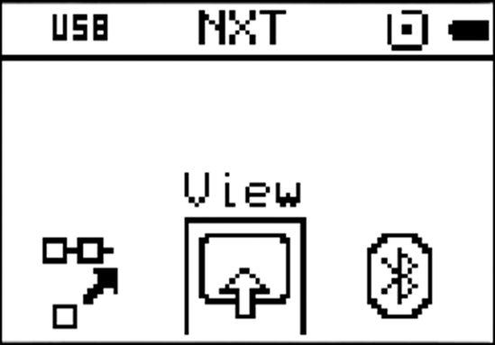
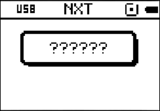
Turn on the Brick, and use the Left/Right buttons to select View; then press Enter (Figure 12-1).
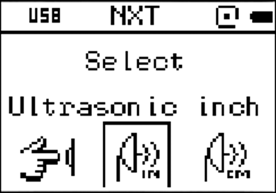
Select the Ultrasonic inch option as Figure 12-2 shows and press Enter (choose Ultrasonic cm to display the result in centimeters).
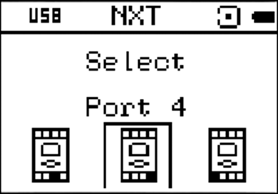
Select the port number for the Ultrasonic Sensor (Port 4 in this case) and press Enter (Figure 12-3).
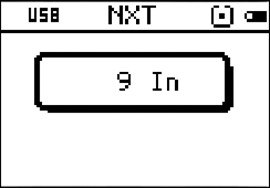
The LCD screen should display the distance from the Ultrasonic Sensor to the wall/object; Figure 12-4 shows a sample reading of 9 inches.
If you select an incorrect Port number in step 4, you’ll see the screen that Figure 12-5 shows. If you get this error, press the dark gray Cancel button, and then return to the screen that Figure 12-2 shows to select the proper sensor measurement and port number.
The View option built into the Brick is an extremely useful feature, with many more options than simply obtaining the number of degrees or rotations that a motor spins. You can also select the following types of measurements using the View option:
- Reflected Light
The NXT measures reflected light using the Light Sensor, so select this option to obtain the value for this reading.
- Ambient Light
The Light Sensor also measures ambient light; select this option to obtain the value for ambient light.
- Light Sensor (RIS version)
Use this to measure the light value with an RCX Light Sensor.
- Rotation (RIS Rotation Sensor)
This option displays the rotation value of the RIS Rotation Sensor.
- Motor Rotations (NXT)
This option measures the number of rotations the motor has turned.
- Motor Degrees (NXT)
Select this option to measure the number of degrees the motor has turned.
- Touch (NXT)
This option displays 1 when the sensor’s button is pressed and 0 when the button is not pressed.
- Ultrasonic inch (NXT)
Use this option to view the distance (in inches) between the sensor and a nearby object.
- Ultrasonic cm (NXT)
This option displays the distance (in centimeters) between the sensor and a nearby object.
In Chapter 14, we discuss how to use these values in programs to give your robot the ability to make decisions based on external factors such as lighting, distance from objects, and distance traveled.
While we’re on the subject of the NXT Brick, we bring your attention to a feature that some call an annoyance and that isn’t often talked about. The NXT Brick is configured to turn itself off automatically after a certain period of inactivity; the default is 10 minutes. While it’s a good idea to have your Brick go to sleep between practice runs to save battery power, the last thing you want during the competition is for your robot to turn itself off as it waits for the game to start.
During competition, set the Sleep mode to 30 minutes, 60 minutes, or Never by following these steps:
Turn on the NXT Brick.
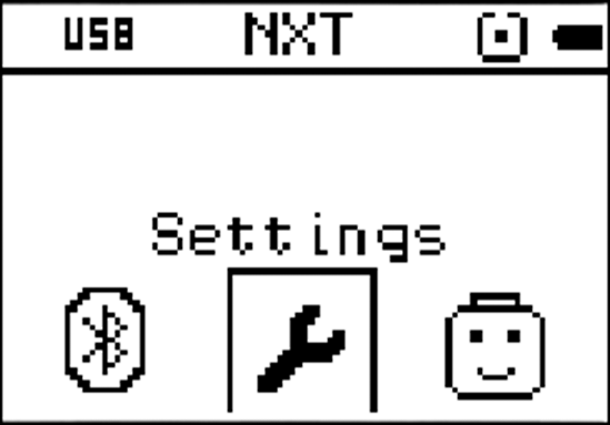
Select Settings (Figure 12-6) and press Enter.
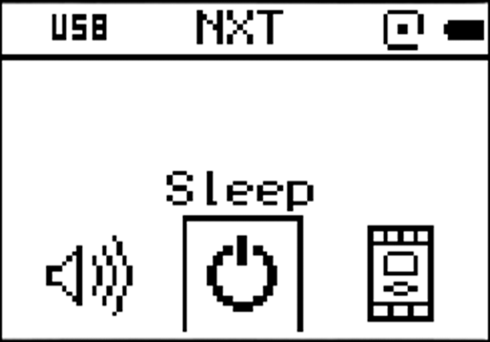
Select Sleep and press Enter (Figure 12-7).
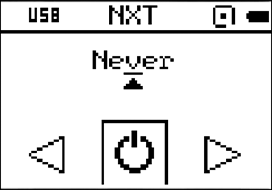
Use the Left/Right buttons to cycle through the options, and press Enter when the desired setting appears on the screen. (In Figure 12-8, we selected Never so the robot only shuts down if a user turns it off or the batteries die.)
The RIS can measure the rotations of a motor using a Rotation Sensor. On the NXT, the Rotation Sensors are built into the motors, and you can program each motor to rotate (forward or backward) a specific number of degrees or rotations, allowing you to fine-tune your robot’s movements.
Use the Brick’s onscreen View option to obtain the number of degrees or rotations required for a robot to make a specific turn. The value obtained is often extremely accurate, but at other times, it will require some testing and fine tuning.
For example, Figure 12-9 shows how a robot might pivot 90 degrees to its right.
Note
The LCD screen is typically considered the robot’s “face,” and left/right is based on the direction the robot faces. Left and right are typically referenced from the robot’s perspective.
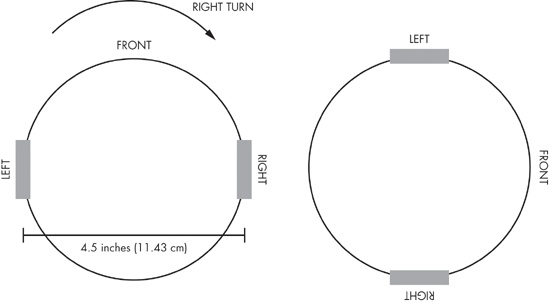
In Figure 12-9, we want the robot to rotate clockwise. The wheel on the right will not move, and the wheel on the left will rotate so the robot makes a right turn. Test this for yourself by building a simple robot such as a TriBot (two motorized wheels and one using a caster or other type of wheel).
Before proceeding with your measurement, connect all the motors that will move the robot. When using two or more motors, be sure to connect them all before taking your measurement. Once everything is in place, use the following steps to obtain an accurate reading of a motor’s spin in degrees:
Turn on the NXT Brick.
Select View (see Figure 12-1) and press Enter.
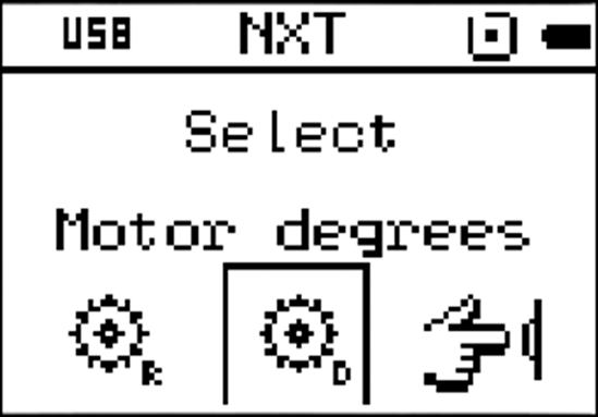
Select Motor degrees as Figure 12-10 shows and press Enter.
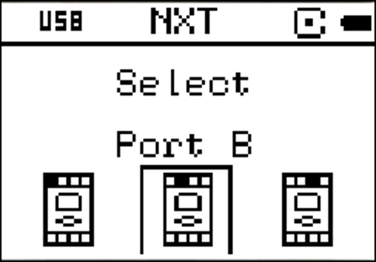
To pivot the robot to the right, turn motor B forward (preventing motor C from rotating), and observe the value on the LCD screen that represents the number of degrees that motor B rotates. To do so, choose Port B (Figure 12-11) and then press Enter.
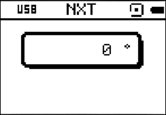
Once you select port B, the value for motor B is displayed on the screen; if the robot has not been moved, a value of 0 degrees should appear, as Figure 12-12 shows.
Note
If the value displayed is positive, this indicates that the motor is rotating in a forward direction. If the value is negative, it indicates that the motor is rotating backward. Take this into consideration when programming the motors for forward/backward direction.
Slowly rotate the robot to the right, and watch the value on the LCD. The final value displayed tells you the number of degrees you need to turn your robot so it pivots. This value depends on the wheel sizes you use as well as how exactly you measured the turn. Record the value so you can refer to it later when programming your robot to make a 90-degree right turn. Note that if the value for a forward B motor movement is positive (+) 183 degrees, then the movement for motor B to spin in the opposite direction (and return to its starting position) will be negative (−) 183 degrees. After motor B rotates and the robot turns 90 degrees to the right, the LCD screen displays a new value (Figure 12-13).
Follow the above steps to obtain values in units of rotation, but be warned that the readings will appear as integers (1, 2, 3, and so on); the NXT can only display integer values of rotations and not partial rotations. You will never see a displayed result such as 3.2 or 5.9 rotations; instead, the NXT rounds the values to 3 and 6, respectively.
If you wish to use rotations instead of degrees, simply choose Motor rotations in place of Motor degrees as the measurement option.
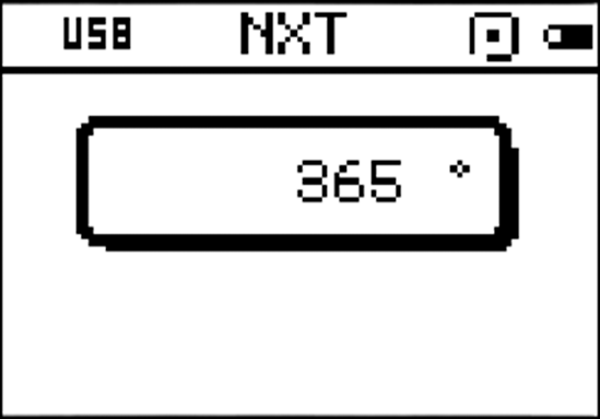
A confusing situation that often comes up is this: “If I need my robot to rotate 90 degrees to the right, why can’t I simply program the robot to rotate 90 degrees?” In our previous example, we obtained a value of 365 degrees, so why does it take a value of 365 degrees and not 90 degrees to rotate to the right?”
Take a look at Figure 12-9 again. To calculate the rotation distance for motor B, you need values for a few items first, including the tire diameter, tire circumference, and the distance between the tires (the radius, measured from the center of the right tire to center of the left tire). For our example, we use the standard rubber tires that come with the NXT Retail and Education Kits. We also use the TriBot model (which you can build using either kit) to measure the distance between the tires. We need the following values:
Tire diameter = 2.25 inches
Tire circumference = approximately 7 inches
Distance between the tires = 4.5 inches
If we rotate our robot to the right (or left), we need to determine the total distance the rotating wheel attached to motor B will turn when the movement is completed, as Figure 12-14 shows.
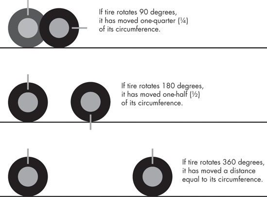
Examining Figure 12-14, we can determine that if motor B rotates 90 degrees, the tire will rotate 25 percent of its circumference, because 90 degrees is one-quarter or 25 percent of the total number of degrees in a circle. We multiply 0.25 (25 percent) by the tire’s circumference (7 inches) to obtain a result of 1.75 inches. This means that if motor B rotates 90 degrees, the tire mounted on motor B moves a total distance of 1.75 inches.
But a tire rotating 1.75 inches isn’t enough for the robot to rotate the required distance; if you try it using the TriBot, you’ll see that the robot doesn’t make a complete 90-degree turn to the right. Motor B must rotate some more to make the actual 90-degree turn.
Hopefully, you can see where the confusion arises: While motor B rotated 90 degrees, the wheel did not make the correct number of rotations to actually move the robot the distance that the arc requires. The number of rotations the robot turns doesn’t equal the number of rotations the motor spins; when the motor rotates 360 degrees, the wheel has actually moved 7 inches (the tire’s circumference) on a flat plane (Figure 12-14).
Now that we understand there’s not a one-to-one correspondence between the motor’s rotation and the robot’s turning angle, let’s calculate the amount that the wheel needs to rotate (in degrees) to turn the robot the required 90 degrees:
Determine the complete distance, or the circumference, the robot will travel if it rotates motor B to turn in a complete circle (360 degrees), returning to its starting point. The formula for this is simply pi (3.14) multiplied by the diameter of the circle in which the robot turns, where the diameter is 2 times the radius. The radius of the circle is the distance between the centers of the two tires (the width of the robot), which is 4.5 inches. Therefore, motor B’s total movement would be 3.14 × 9 inches (9 inches is the diameter: 2 × 4.5 inches), which is 28.26 inches.
For the robot to make a complete rotation (rotating only motor B), the wheel on motor B needs to travel 28.26 inches. However, we’re only rotating our robot 90 degrees, or one-fourth (0.25) of a complete rotation. Therefore, the wheel on motor B should travel 0.25 × 28.26 (or 7.065) inches.
Now divide 7.065 inches by 7 inches (the circumference of one wheel) to get a value of 1.009. This is the number of rotations the wheel has to make to complete the pivot turn. Finally, convert to degrees by multiplying 1.009 by 360 degrees. The result, 363.24 degrees, is very close to the actual measured value we obtained using the View option that Figure 12-13 shows.
The numbers are almost identical (365 versus 363.24); the point we want to demonstrate is that you can calculate distances fairly accurately before you ever attempt to program the values into your program. Every robot is different, so you’ll quickly find that you will often have to make some minor tweaks to the values for degrees and rotations to get the robot to perform the exact movements you desire. In this example, if we had programmed our robot to rotate 363 degrees and run the program, the robot would have come close, but not exact, to the actual 90-degree-arc turn we desire. With tweaking, we would find that a value of 365 would get us the desired rotation.
Note
When programming your robot, you always need to fine-tune calculated values through testing to get the actual value used by your robot. You can also program the motors to rotate for a specific period of time (in seconds), but this is generally considered not as reliable for guaranteeing that a motor will rotate a specific number of degrees or rotations.
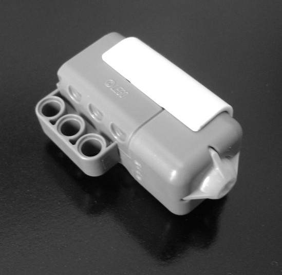
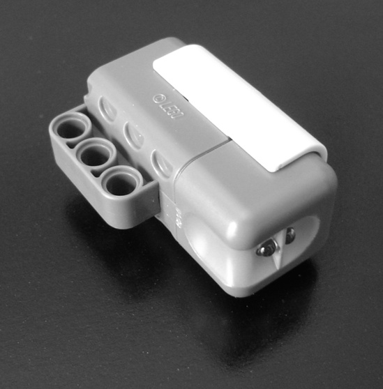
The NXT Touch Sensor (shown in Figure 12-15) is a device that can provide your robot with simple decision-making abilities (for example, if the button is pressed, turn right and if the button isn’t pressed, continue in a straight line). This sensor has three settings: Pressed, Released, and Bumped. Here’s how each of those settings works.
When the Touch Sensor button is pressed and held down, we consider it Pressed. The robot’s program generally interprets Pressed as a collision with an object or wall. While this is the typical use for the Touch Sensor, you can also use the sensor to prevent your robot from going over the edge of a table.
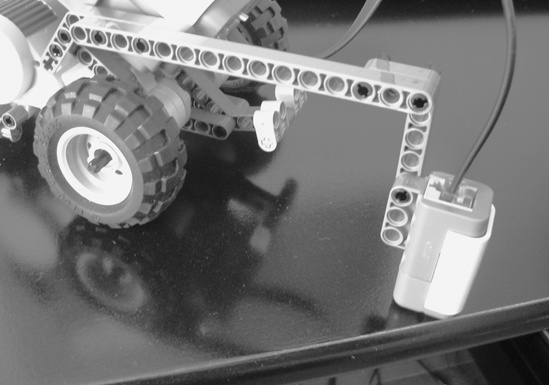
For example, if you mount the Touch Sensor pointing downward, with the button always pressed by the pressure exerted against the tabletop, you could use the sensor to detect when the robot reaches the table’s edge. When the Touch Sensor reaches the table’s edge and the button is released (when the tabletop disappears, the sensor button is no longer pressing against it), you can program the robot to react to this changed condition. If the sensor is mounted away from the body of the robot and its wheels (possibly on a long beam in front of the robot—see Figure 12-16), you can use it to give the robot time to stop and adjust its course.
When the Touch Sensor is mounted, for example, on the front, rear, or sides of the robot, it can detect collisions with objects (or walls) from the side on which the sensor is mounted. Add clever design to a robot using beams and other TECHNIC components to create a bumper that expands the sensitivity of the Touch Sensor by increasing the surface area that triggers the sensor (demonstrated in Figure 10-22 in Chapter 10). Notice that the robot can detect collisions from a much larger area than the size of the button.
The Touch Sensor is considered Bumped when its button is pressed and released in less than one second.
You can use the Bumped state as a start button for the robot. For example, we can start the robot’s program by pressing Enter but have the robot wait to begin its actions until the Touch Sensor is Bumped. (To do this, simply place a Wait block at the beginning of your program, and configure it to wait until the Touch Sensor is Bumped. Once that happens, the rest of the program will begin to execute.)
Note
When using the Touch Sensor’s Bumped condition, be sure to place the sensor so it isn’t accidentally bumped when the robot begins to move.
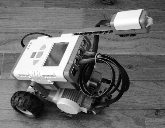
Figure 12-17 shows an example of a robot with a Touch Sensor mounted for easy access.
Note
Chapter 14 provides an example for programming the Touch Sensor.
The FLL mat used in the Robot Table portion of the competition is very colorful, with a mixture of graphics and text, each of which you can use as landmarks. Use your Light Sensor to distinguish between these landmarks and control your robot’s movements much more accurately.
Note
The mat will change year to year, so teams should always take a good look at the colors, lines, graphics, and other items on the mat and determine if any will make good landmarks, waypoints, or lines to follow using the Light Sensor.
Figure 2-1 in Chapter 2 shows the mat used in the Power Puzzle competition. The image is not in color, but it helps to point out a few important items:
Black lines (representing roads) crisscross the mat at various locations.
A large blue mass indicates water, and brown graphics represent the boat dock.
Red squares represent houses.
The NXT Light Sensor (Figure 12-18) can distinguish between most colors by converting them to grayscale and comparing the reading to built-in values.
Chapter 14 provides a sample robot program that uses the Light Sensor. For now, the following are some examples of how you might use the Light Sensor and landmarks on the mat to better control your robot:
Program the robot to reverse direction for one rotation when the Light Sensor detects the color blue.
Program the robot to follow a black line (a road) to ensure movement in a straight line.
Program the robot to use color to distinguish between “good” objects that must be returned to Base and “bad” objects that should stay in place.
Note
Besides detecting color, the Light Sensor can also detect differences in the level of lighting. This ability isn’t used very often in FLL competition (the robot is typically operating in a well-lit room with no dark areas on the mat). However, an interesting trick takes advantage of the Light Sensor’s ability to detect changes in light readings, which essentially converts a Light Sensor to a third Touch Sensor (as demonstrated in Chapter 10).
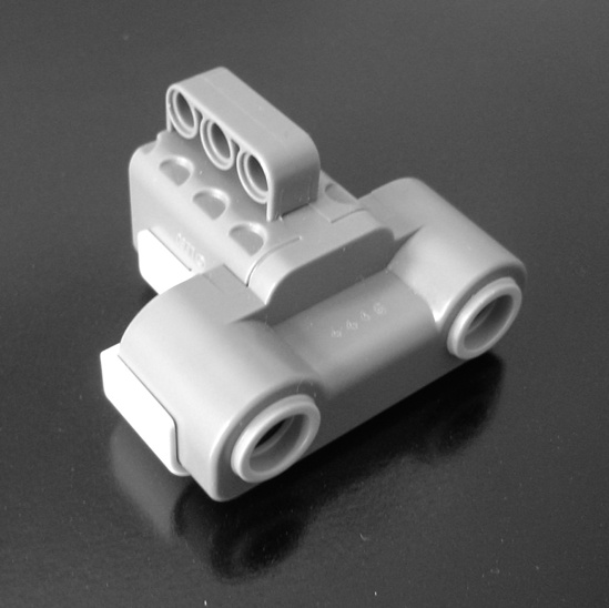
The Ultrasonic Sensor (shown in Figure 12-19) is one of the more powerful sensors available. It gives a robot the ability to measure distances from objects and walls and to detect obstacles. And, unlike the Touch Sensor, which requires the robot to collide with an object or wall, the Ultrasonic Sensor allows a robot to avoid collisions altogether.
Note
Chapter 14 covers programming a robot to use the Ultrasonic Sensor.
The Ultrasonic Sensor works by sending out a sound wave that bounces off objects and walls and returns to the sensor, like radar or sonar. The NXT Brick measures the time that elapses while sending out the signal, bouncing it off an object, and the sensor receiving it again. This detection ability is surprisingly accurate; perform some tests of your own to verify that the sensor correctly measures the distances (in inches or centimeters).
With one Ultrasonic Sensor, this detection ability works well, but more than one sensor in an immediate area can create pandemonium if the signals interfere with each other. If another team is also using an Ultrasonic Sensor on its robot, the signals are indistinguishable from one another, so your sensor might get inaccurate readings if it detects the other team’s signal instead of your own.
One way to overcome this problem is by using the 4-inch-high walls of the Robot Table. By mounting the Ultrasonic Sensor low on the robot so its sound wave bounces off the wall, a sound wave sent out by your Ultrasonic Sensor will (hopefully!) be blocked and bounce off the wall, not interfering with the other team’s robot (assuming the other team is also using the Ultrasonic Sensor).
Not all FLL teams use sensors when fielding their robots; there are pluses and minuses to using sensors and ways to avoid their use altogether. Many teams continue to program their robots using only the simple NXT-G Move block. In fact, through careful testing and measurement, teams can use the Move block to program their robots to move very specific distances (to one degree or one one-thousandth of a rotation). This type of pre-programmed movement is often referred to as dead reckoning and point-and-shoot movement.
Problems do come with using only Move blocks, however. Some common ones are related to the robot’s inability to react to changes in its environment. Consider the following potential problems:
Extremely small differences in width and depth of competition tables can result in a robot moving too far or too little over long distances. For example, if the table has been constructed one-eighth of an inch deeper than regulation and the mat is flush against the back wall, you need to program your robot to travel one-eighth of an inch farther than normal if its starting position doesn’t change.
If a robot rolls over a small object on the table, it can alter its course drastically, resulting in a table rescue and a loss of points. When you don’t use a sensor, your robot cannot respond to changed conditions.
Multiple activities on the mat require very precise movements. If the robot is off by just a little bit during one mission, that error can trickle down and affect subsequent missions before the robot returns to Base.
The battery level of a robot can affect its movements. For example, a robot at 70 percent power might move differently than one at 100 percent power.
Robots that do not use sensors may not be able to correct their course easily. When using dead reckoning, be sure to position a robot very accurately in Base before attempting a mission.
This is not to say that sensors don’t have their own problems. For example, as we already mentioned, the Ultrasonic Sensor can return incorrect readings if a second one is nearby, but consider a few other things when using sensors:
Light Sensors can sometimes be extremely finicky when it comes to detecting colors, let alone the difference between black and white. Be sure to test your Light Sensors in a variety of lighting conditions.
If a Light Sensor is close to the floor, bumps on a field mat can hamper its ability to correctly detect lines or colors, since they may affect the way that light is reflected.
For Touch Sensors to distinguish between a Pressed state and a Bumped state, the pressing action must last longer than one second. This means the sensor’s button must be solidly pressed and not just “brushed” by a passing object if it is to be considered in a Pressed state. If the button is quickly brushed by a nearby object, the Touch Sensor will treat this collision as a Bumped action, since the press-and-release took less than one second. Program your robot accordingly.
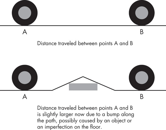
The Rotation Sensors (built into the NXT motors) work very well when the motors are rolling on a completely flat surface. You can measure distances accurately, but if one or more wheels go over a small bump or object, the programmed distance hasn’t changed but the distance traveled on the surface has changed (although it is a very small change) as seen in Figure 12-20.
Sensors have the potential to be a robot’s most valuable secret weapon. When integrated and properly programmed, your robot moves from a simple “point-and-shoot” device to a responsive, “intelligent” teammate. When every obstacle and imperfection on the mat becomes a factor in the success or failure of a robot programmed with only Move blocks, sensors can provide your robot with a real advantage in navigating its way through missions. Give serious consideration to integrating sensors into your robot’s design; as competitions continue to increase in complexity, sensors may very well become an absolute necessity. Next year, you may find that sensors are no longer optional but standard equipment. Experiment and learn how to use sensors now so your team is ahead of the game this year and next.