
![]()
Throughout the book, you’ve slowly been building and testing a line-following circuit on a solderless breadboard. That’s a good way of designing and proving a circuit, because there’s no reason to solder something together until it appears to be functional.
Some builders attach their solderless breadboard to a mobile platform and pronounce their robot complete. Unfortunately, the vibrations and handling can cause the wires and components to slip out of the holes, either intermittently or completely. Ultimately, the robot functions poorly (if at all) and has a limited lifespan.
In this chapter, you’ll transfer your line-following circuit to a board and solder it all together. Don’t attempt soldering a circuit until you’ve finished soldering the switches and motors in the prior chapter, as you’ll perform better with some soldering experience.
The Line-Following Circuit
The final line-following circuit is presented as a wiring diagram in Figure 23-1.
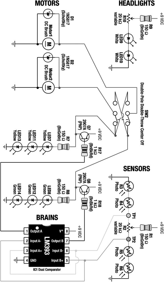
Figure 23-1. (next page) Wiring diagram of the final line-following circuit
The final line-following circuit consists of identifiable modules of circuits from prior chapters.
- The sensor module is the balanced brightness-sensing circuit
- The headlight module is the headlight circuit
- The brains and LEDs modules are the brightness comparator circuit with transistors
- The motor module is the motor and Schottky diode circuit
A couple of minor changes were made to make the robot “kit friendly” or “production friendly:”
- Two 470 Ω resistors (R1 and R9) were replaced with 150 Ω resistors to make it less complicated for someone to offer this line-following robot as a kit. Now, only 1 kΩ and 150 Ω resistors are in the circuit. The reduction in values shouldn’t pose a problem, since the resistor values are still large enough to limit current extremes.
 Note Recall that resistor value selection can be an art. Earlier in the book you had to choose a resistor value that either leaned toward making an LED brighter with shorter battery life, or saved power but made the LED dimmer.
The change presented in Figure 23-1 represents another potential resistor value selection methodology: You can consolidate on common values in a design so that components can be purchased in bulk. Schools or companies producing multiple copies (or kits) of this robot can save money by purchasing greater quantities of just a few resistor values, rather than lesser quantities of many resistor values. Additionally, the person assembling the robot has fewer opportunities to insert the wrong value resistor, because there are fewer resistor values from which to choose.
- A 20 kΩ variable resistor (R10) has been added to the headlights to allow their brightness to be adjustable on the robot. The value of 20 kΩ was chosen so that R10 and R2 are matching parts. Again, this makes it “kit friendly.” However, because you are unlikely to ever dial down the headlights to be that dim, a 2 kΩ value would have been preferable if not for the kit advantages.
Feel free to test these modifications on your solderless breadboard before committing them to a soldered circuit.
Tweaking For Better Performance
Before we continue, let’s discuss the opposite strategy for selecting resistor values for R1 and R9. Instead of designing for a kit, what optimal values should you select if you want to tailor the resistors for the unique components sitting in front of you now?
You would want to find a value for R9 that permits your headlight LEDs to be as bright as safely possible and select a value for R1 that is correlated with your sensors. These customizations help ensure that the sensor voltages for your specific robot are in the range that IC1 can compare. That means your robot will be able to accurately follow a line at faster speeds.
Because different types of white LEDs vary significantly in voltage drop and brightness, and because cadmium-sulfide sensors vary significantly even in the same batch, there is no way to select a “perfect” value in a book. Yet, the kit values work just fine for most people.
If you want to try to determine the best value for your white LEDs, set up the headlight portion of the circuit in Figure 23-1 on a solderless breadboard (you don’t need the other parts of the circuit for these tests). Then, proceed as follows:
- Temporarily replace R9 with a low resistance, say 40 Ω to 50 Ω.
- Dial R10 to any value over 200 Ω.
- Insert a multimeter in mA mode between R10 and LED9. That is, R10 and LED9 should NOT be connected together. The multimeter’s red lead should be in the mA socket and it should attach to the bottom of R10. The black lead should be in the COM socket and should attach to the top of LED9. Electricity has no choice but to pass through the bottom of R10, into the multimeter to be counted, and out to the top of LED9.
- Apply power from a fresh battery (usually near 9.6 V). You’re trying to find the absolute maximum brightness.
- Carefully adjust the dial on R10 until the meter reads 30 mA. The dangerous thing about this is that R10 could accidently get adjusted to zero ohms, and with R9 so low, the battery could fry the LEDs. Therefore, adjust the dial very slowly.
- Disconnect power from the circuit.
- Remove the multimeter and attach the bottom of R10 to the top of LED9. They are now reconnected like it shows in the schematic.
- Change the multimeter to resistance mode. The red lead should be in the Ω socket and the black lead in COM.
- Connect the multimeter’s red lead to the top of R9 and the black lead to the bottom of R10. This measures the combined resistance of R9 and R10. That’s the final value you want to use for your robot’s R9.
Using the white LEDs in the Solarbotics kit, and adjusting R10 until 30 mA flowed through them, I measured the resistance for R9 and R10 to be 106 Ω. That’s close enough that I’ll use a 100 Ω resistor for R9. Now, if the robot struggles to follow a line, I can adjust the headlights to be significantly brighter with a 100 Ω resistance, instead of 150 Ω resistance.
The second optimization, choosing a value for R1, is almost all mathematical.
One at a time, measure the resistance of your cadmium-sulfide sensors under a desk or in a relatively dark place. Don’t completely cover them up. You want an idea for the maximum resistance when they are looking at a black line or black surface.
- Assuming you’re going to evenly distribute the sensors, calculate the “dark” values of each pair. My examples were 150 kΩ, 500 kΩ, 400 kΩ, and 550 kΩ. So, 550 kΩ is the maximum. I’d pair 150 kΩ with 550 kΩ = 700 kΩ, and 500 kΩ with 400 kΩ = 900 kW.
- Now use this formula: R1 = ((pair1 * pair2) / (pair1 + pair2) - (R2 / 2)) * 0.25. This calculates the resistance of the sensors in parallel, minus the resistance of the potentiometer for one of the sensor branches, with an approximate percentage that would provide the comparator’s required top-end 1.5 V when the battery is almost exhausted (7 V). For my example: R1 = ((700 kΩ * 900 kΩ) / (700 kΩ + 900 kΩ) - (20 kΩ / 2)) * 0.25 = 96 kΩ.
Wow! 96000 Ω is much greater than the book’s default 150 Ω. Remember, this proposed change is to handle the extreme case where all of the sensors are looking at a dark surface. Usually, at least one of the sensors sees a bright line. The potentiometer resistance provides more than enough voltage drop during normal operation. If you’re at all concerned about making such a major change, particularly given that it may alter the normal performance, you have some choices:
- Leave R1 with the 150 Ω resistor. You can always turn up the headlight brightness.
- Compromise and install 10 kΩ. (Probably the best choice.)
- Install a 100 kΩ resistor but be prepared to solder a 10 kΩ or smaller value resistor on top of it. This trick works because electricity is lazy. It will take the less-resistant path. (You’ll end up with a total resistance of around 9 kΩ.)
- Leave the 150 Ω resistor and replace the LM393 comparator with a LMC6772BIN comparator (Digi-Key $2.77). The LMC6772 can compare voltages over the entire range, and thus won’t be affected if the sensors all see darkness.
Point-to-Point Soldering Versus a Printed Circuit Board
At this point, you have built and tested the line-following circuit on a solderless breadboard with either the default or custom values. There are several methods of creating a soldered circuit. You can obtain a blank, solderable breadboard (see left side of Figure 23-2), insert the components, and solder wires from each component lead to the other. This is called point-to-point soldering.

Figure 23-2. The top of a breadboard (left) and the top of a printed circuit board with the line-following circuit (right) before soldering
The other method is to obtain (or make) a printed circuit board (PCB, see right side of Figure 23-2) where all the wiring is built onto the surface of the board. In that case, the parts need only be inserted into the correct holes and soldered into place.
Point-to-point soldering is faster and cheaper for one-time small circuits. After all, there’s up-front effort required to design and etch a printed circuit board yourself. Also, since ordinary wires in a point-to-point board connect all of the parts, you can arrange (or fix) the circuit somewhat more easily by desoldering and resoldering the wires.
Obviously, buying a pre-printed circuit board with the line-following circuit is much easier and faster. There’s a lot less soldering to do. Not only that, but if the circuit has been previously verified as being correct on the board, then you don’t have to be concerned about miswiring the circuit.
Looking at the end results, there are a couple of other factors that make printed circuit boards better than point-to-point-soldered circuits. As illustrated in Figure 23-3, the point-to-point circuit (on the left) is much messier, takes up more space, and is more likely to fail (due to loose wires) than is the printed circuit (on the right).

Figure 23-3. Underside of breadboard showing point-to-point wiring (left) and printed circuit board (right) after soldering
I’ve created the line-following robot both ways: with point-to-point soldering and with a printed circuit board. Because there aren’t an overwhelming number of connections and because you can build the board up in modules, any beginner should be able to create the circuit using point-to-point soldering. Point-to-point instructions follow in the next sections of this chapter.
However, I highly recommend purchasing a printed circuit board with the line-following circuit from Solarbotics (#SandPCB $12), even if you don’t buy the full kit. This will save you soldering, frustration, and debugging, so that you can more quickly reach the goal of experimenting with your finished robot. It’s not cheating to use a PCB since you’ve already built the circuit on a solderless breadboard. It’s an optimization of your time.
Instructions for stuffing the ready-made PCB are posted at http://www.robotroom.com/SandwichPCB.html.
Point-to-Point Soldering the Line-Following Circuit
Soldering the line-following circuit is the most arduous part of building Sandwich. But, the soldering practice you’ve had with the motors and switches should help a lot. Be patient.
If possible, obtain a second set of parts so that the original parts from the tested circuit can remain on the solderless breadboard. The line-following circuit components should cost less than $10.
If you’re not buying the PCB, obtain a perforated breadboard (also called perf board, stripboard, or prototyping board) that is approximately 7 cm (or less) by 10 cm (or less), with 700 or more holes spaced at 0.100 of an inch. Each hole should have copper plating around it. Examples are: All Electronics #PC-4 $2.00 or Adafruit.com #723 $5.95 or #1609 $4.50.
Laying Out the Line-Following Circuit Components
A grid-style solderable breadboard is more freeform than a solderless breadboard. You can change the positions of components considerably from the rigid 5-position groups imposed by the solderless breadboard. Since the robot is going to be stuck with whatever arrangement you solder together, take some time to carefully plan the positions of the components.
Placing Components with a Helping Hand
- Place the board on a Helping Hand tool (see Figure 23-4).

Figure 23-4. Helping Hands makes laying out a circuit board much easier
- Highly Recommended: Test components with a multimeter before placing them on the breadboard. This gives you a sense of confidence in their quality and values before permanently soldering them in place. At the very least, measure the trimpots and center them to their middle resistance.
Note After being soldered into a circuit, it isn’t always possible to accurately measure the resistance or diode test the individual components using a multimeter. This is due to the fact that the components to which they are connected may loop back electricity to the opposite multimeter test probe, thus skewing values.
- Lay out the components onto the breadboard (see Figure 23-5). Try to place components so that they are nearest the other components to which they will connect. This reduces the length of the wires and reduces the number of wires that cross over each other.
Example Layout
A suggested layout appears in Figure 23-5. Notice that the LEDs are distributed on the far sides to increase visibility. The comparator is in the center flanked by transistors because the comparator connects to the greatest number of components. The brightness balancing and headlight brightness-adjusting trimpots are far forward to make them easy to reach from the front of the robot.
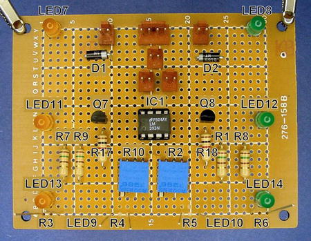
Figure 23-5. Breadboard with line-following circuit laid out. R3, R4, R5, R6, LED9, and LED10 are on the underside of the board
All of the Molex connector headers are located at the rear of the board. This makes sense since all of the switches, motors, and other parts are at the back of the robot body. The locking ramp of each header faces away from the center of the board to provide strain relief and help retain the connector in place if the wires are pulled away from the board.
Use an IC socket (see Figure 23-6) instead of soldering the comparator chip directly to the circuit board. That way, the comparator is spared the heat and abuse of the soldering process. Also, you can substitute a more capable or advanced comparator (such as the TLC393, TLC372, TLV3402, or the LMC6772) in the circuit, as long as the new comparator is pin-compatible with the LM393.
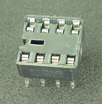
Figure 23-6. 8-pin DIP IC socket to allow chip removal
Notice the notch on one side of the DIP (dual inline package) socket. This corresponds to the notch in the chip to indicate the direction in which the chip should be aligned. Table 23-1 lists suppliers of 8-pin DIP IC sockets.
Table 23-1. Suppliers of 8-Pin DIP IC Sockets

Keeping the Components on the Board During Soldering
After all the work you’ve invested in carefully laying out the components on the breadboard, you don’t want the parts spilling out when you turn the board upside down for soldering. Here are a couple of common techniques to prevent that.
Gluing the Molex KK Headers to the Circuit Board
The pins of Molex KK headers are slightly loose in the holes of standard breadboards. When the board is turned over for soldering, the Molex headers slip out slightly or even fall out completely. (This won’t occur with appropriately sized holes of custom PCBs.) It is very important that the headers are soldered completely flat against the board, otherwise they may wiggle or rip out when attempting to make a connection to the housing.
- With a disposable toothpick, apply a bit of adhesive to the edges (not the metal leads) of the Molex headers (see Figure 23-7). This will keep them fully seated on the board during soldering.

Figure 23-7. Adhesive being applied to edges of Molex connnector
I prefer clear silicone adhesive for gluing components to circuit boards (see Figure 23-8). Many adhesives simply don’t stick well to the resin circuit board substrate. Silicone adhesive is a tacky gel, so it’s easy to apply exactly where you want it, it stays put, and keeps the part from sliding around too much before it is dry. Actually, because silicone adhesive doesn’t dry instantly, you can still shift or nudge the part if your initial placement wasn’t accurate.
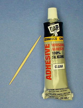
Figure 23-8. DAP clear silicone adhesive with a toothpick for applying
Additionally, silicone adhesive can stand high temperatures, which is a good idea for anything that holds a part to be soldered. Silicone adhesive dries to a rubbery consistency, so you can peel it off if the component needs to be desoldered.
- Reinsert the headers into the desired location on the board.
- Let the adhesive dry for five minutes (or whatever time period is instructed on the package). Don’t solder around adhesives that may still be expelling fumes or that are listed as flammable!
Fortunately, most component leads are much more pliable than the rigid metal pins of connectors. Leads can be bent to hold the component in place so you don’t need to glue them.
- Carefully bend the component leads toward the back of the board so that the components won’t fall out during soldering (see Figure 23-9). Bend the leads only as much as necessary to keep the components in place during soldering; don’t bend the leads completely flat against the board. Solder tends to wick under the flattened leads and contact other pads or components. Also, it’s more difficult to trim off excess length of flattened leads.

Figure 23-9. Side view of a breadboard with a component’s leads bent slightly to hold it in place during soldering
However, with long leads or nearby components, sometimes you can bend a lead enough to reach the lead to which it needs to be soldered. Of course, then you don’t gain the protection of the plastic insulation that a wire would provide.
Creating Power Distribution Buses
Most solderless breadboards have long rows at the top and the bottom to distribute positive and negative voltage to locations near all of the components. Although some solderable breadboards have these buses built on the board surface with copper traces, many breadboards do not.
In any case, it’s not hard to make your own power distribution buses. What’s more, you’re free to design the placement, length, and pattern of these buses yourself.
- Obtain some #22 AWG bare wire. You can always strip off the plastic insulation from wire you already have. However, it’s faster and cleaner to obtain a spool of the bare stuff. Figure 23-10 shows some uninsulated copper wire that has a thin coating of tin to improve solderability.

Figure 23-10. Spool of #22 AWG bare (no plastic insulation) tin-coated copper wire
- Loop some bare wire starting at the positive pin on the Molex header that receives power from the power switch (see Figure 23-11). This bare wire is the beginning of the positive distribution bus.

Figure 23-11. Bare wire shaped to connect to underside of Molex KK connector
- Loop the bare wire up to the top of the board and back down again (see left side of Figure 23-12). Not only does this provide a mechanically strong starting point for the bus wire, but also makes a nice little loop that is perfect for hooking a multimeter probe.

Figure 23-12. Loops atop breadboard to allow attachment of multimeter IC hook probe tips for positive voltage (left) and negative voltage (right)
- Back on the underside, make a long stretch with the bare wire (see Figure 23-13) and solder in place.

Figure 23-13. Underside of breadboard showing long bare wire to provide a distribution bus that can accommodate many connections of wire
- Now, whenever a module circuit needs access to positive power, simply solder a wire to the bare wire that forms the positive-voltage distribution bus (see Figure 23-14).

Figure 23-14. Positive-voltage distribution bus on which many wires are soldered
- Repeat the same technique to form a negative-voltage distribution bus.
Soldering the Remaining Components
The components are laid out on the breadboard and held in place. A positive and negative distribution bus is now available, just as it is on the solderless breadboard. All that remains is to connect the components together, using the solderless breadboard as a model and checking the wiring diagram as necessary.
- Working on a module at a time, pick a component lead and determine where it needs to be connected.
- Determine the approximate distance of the connection and cut a piece of stranded, insulated wire to the desired length, plus some extra length for slack. Any wire diameter from #22 AWG to #26 AWG is acceptable, although I prefer thinner (#26) wire.
- Strip a bit of insulation from both ends of the wire.
- Wrap one end of the wire around the component lead. Alternatively, sometimes you can stuff the end of the wire into the same hole as the component, providing some mechanical strength and lots of electrical contact. Either way, make sure the joint to be soldered has plenty of bare metal exposed for both the wire and the component lead.
- Solder the joint.
- Repeat steps 18 and 19 for the other end of the wire.
- Slowly, but surely, make your way through each circuit module and solder every component. Take breaks as needed.
Soldering the Cadmium-Sulfide Photoresistors
Before soldering the photoresistors, it’s beneficial to paint their backs with black paint. The thick, dark paint prevents direct light from the headlights from leaking from behind and affecting the sensor readings.
Testors Flat Black Enamel #1149 works well (see left side of Figure 23-15). Alternatively, instead of using black paint with a paintbrush, try a black paint marker. They’re easier to guide, which reduces the chances of accidental brush strokes on the face of the sensor. You can find paint markers at local hardware stores or McMaster-Carr (part #16625T27, 4 mm black paint marker, $4.00).

Figure 23-15. Black paint (left and bottom) and photocells raised 12 mm from circuit board surface (top right)
When installed in the robot’s body, the circuit board is about 20 mm above the floor, so the photoresistor and headlight LED leads need to be trimmed short. After soldering, their tips should be about 12 mm from the circuit board surface (see top-right side of Figure 23-15). At the very least, try to keep all of the photoresistors at the same level.
Trimming Leads with Wire Snips
After everything is soldered, use a pair of wire cutters to trim the excess leads from the board. Long leads are likely to catch or tangle, and can accidentally touch other long leads, which causes circuit failure. Be sure to wear safety goggles during lead trimming!
Depending on the flux in the solder you used, it may need to be cleaned from the board. No-clean flux and many of the newer rosin fluxes don’t require cleaning. Read the product label or check with the manufacturer.
Specialty flux cleaning solutions are available if you really want to remove the flux.
Testing the Robot’s Electronics
When everything has been soldered, you may be tempted to immediately install a battery to see the fruits of your labors. However, there are a couple of simple tests you should perform first that may save your battery and circuit board from damage.
The Dangers of a Low-Resistance Circuit
If you accidentally soldered a positive wire to a negative wire, electricity would rush from the positive terminal of the battery, through the shorted connection, to the negative terminal of the battery. The remainder of the circuit won’t receive any current because electricity always takes the short path (direct positive to negative). In that case, the robot won’t do anything.
It’s also possible to have a bad (or missing) part or partially shorted circuit, where one path in the circuit has a very low resistance. In that case, a current-sensitive component, like an LED or chip, may not be getting the protection it was supposed to be receiving from a resistor.
In any case, a shorted or very low resistance in a circuit consumes battery power quickly and generates excessive heat. The heat is likely to damage components on the board, and finding the newly damaged parts can be difficult.
Examine each part to ensure that it has been wired to something. A two-lead part with only one end hooked-up indicates something is amiss. Every pin and every lead in Sandwich’s circuit should be connected to a bus or another part.
Checking All Leads that Connect Directly to Positive Voltage
Electricity needs a path from the positive battery terminal to the negative battery terminal in order to flow. By examining all the connections made to positive voltage, you can be sure that each of the paths starts out correctly.
Begin with the 9 V battery. Make sure that the red wire from the battery snap is hooked up to the positive pin on the Molex connector. The positive pin on the Molex connector should be wired only to the power switch connector. That is, power from the battery should not be allowed to enter the circuit unless it first passes through the power switch.
![]() Note When the power switch is off, absolutely no current can flow from the battery because nothing else but the power switch is connected to the battery’s positive terminal. Therefore, the robot doesn’t consume any power at all when the power switch is off. It’s as though the battery weren’t installed.
Note When the power switch is off, absolutely no current can flow from the battery because nothing else but the power switch is connected to the battery’s positive terminal. Therefore, the robot doesn’t consume any power at all when the power switch is off. It’s as though the battery weren’t installed.
Even so, it’s a good idea to remove the battery if the robot is going to be stored for long periods of time. Aging batteries can leak corrosive chemicals.
The other pin of the power switch’s Molex connector should be wired to the positive voltage bus. Double-check all wires connected to the positive voltage bus. Most of them should be going to resistors. In Sandwich’s circuit, the exceptions are the collector pins on two transistors and pin 8 on the comparator IC. Everything else runs through resistors.
Measuring the Resistance of the Entire Circuit
After completing the visual inspection, here are a few quick multimeter tests that can spot some problems.
Note: Toward the end of the book, I recommend the addition of a diode between the power switch and the rest of the circuit that protects against damage from a battery installed backwards. The resistance tests described in this section won’t work through the diode. So, if you choose to include the diode, you’ll need to temporarily install a wire (alligator or hook jumper) to both ends of the diode so that the multimeter power can skip around it during resistance testing.
Measuring the Power Off Resistance
- Attach all of the parts that have Molex connectors to the finished circuit board (see Figure 23-16). That means the motors, power switch, battery snap (without battery), line-following switch, and tube LEDs (if desired) should now be connected to the circuit board.

Figure 23-16. Testing resistance of circuit through 9 V battery snap connector
- Connect the multimeter’s test probes to the positive and negative snaps of the battery connector (it helps to use alligator clips or IC hooks). Note that the battery is not installed! The multimeter is pretending to be the battery.
- Dial the multimeter to measure resistance (Ω).
- Turn on the multimeter.
- Toggle the robot’s power switch back and forth. In one direction, the resistance should be infinite. That’s power off.
If you don’t get an infinite resistance in either switch position, something is wrong with the power switch or its connections. Recall that in an off state, the positive entrance to the circuit is completely disconnected, thus the infinite resistance to electricity trying to enter the circuit.
Measuring the Power On Resistance
- Toggle the robot’s power switch to the power on position.
- The resistance should be between 5 kΩ and 50 kΩ.
A value of infinity, with the power switch on, suggests a wire is missing or broken between the battery, power switch, and either power bus.
A value below 1 kΩ suggests a partial short circuit or bad component. Then again, a trimpot could be dialed to a minimum value.
Anything below 10 Ω indicates a serious short circuit! If you find that’s the case, absolutely do not connect the robot to a battery. Trace each circuit and wire to find the cause. Switching the multimeter to continuity mode and touching the test probes between stretches of components can help find the problem.
Measuring the Sensor Resistance
- Cover the photoresistors with your hand. The resistance of the circuit should be quite high. Sandwich measures 45 kΩ.
- Expose the photoresistors to light. The resistance of the circuit should be lower. Sandwich measures about 5 kΩ when held against a light bulb.
If the resistance doesn’t vary with the amount of light the photoresistors are receiving, then the sensor circuit isn’t correctly wired to the positive and negative bus. Or, maybe there’s a bad solder joint somewhere in the sensor circuit.
There are some semiconductors in the circuit that won’t pass significant current until the voltage from the meter exceeds 0.5 volts or better.
- With the meter test probes still connected to the battery snap, switch the multimeter dial to diode mode.
- When the robot’s power switch is in the off position, the meter should display “open” or “infinity.”
If the meter indicates that any voltage is being dropped through the circuit when the robot’s power switch is in the off position, that should warn you that the power switch isn’t completely disconnecting the robot’s circuit from positive voltage. It is not safe to connect the circuit to a battery until you’re sure that the power switch works.
- When the robot’s power switch is in the on position, the voltage coming from the multimeter should be high enough to cause diodes, chips, and transistors to conduct. For Sandwich, the multimeter displays “good” or 0.742 V.
Your meter may give slightly different readings, but there should be a noticeable change from the robot’s power off switch position. In diode test mode with the switch in the on position, anything above 1.6 V or below 0.4 V is suspect.
If at some point during testing you discover a weak or loose solder joint, it might be worth briefly reheating all of the solder joints on the board to ensure they’re completely bonded. You probably don’t need any more solder, just touch the soldering iron tip to each joint until it melts completely. That should cause the solder to flow through and coat the joint.
Unlike wire stripping, wire attachment, and soldering, the reheating process is fairly quick. Five minutes spent guaranteeing clean joints saves a lot of frustration in debugging.
![]() Caution Never solder or reheat joints when a circuit is powered on. The combination of heat from the soldering iron and heat generated by electrical flow permanently melts apart the tiny bonds and leads within semiconductor component cases. Also, brief short circuits can result from the edge of a molten solder blob accidentally contacting multiple traces, leads, or wires.
Caution Never solder or reheat joints when a circuit is powered on. The combination of heat from the soldering iron and heat generated by electrical flow permanently melts apart the tiny bonds and leads within semiconductor component cases. Also, brief short circuits can result from the edge of a molten solder blob accidentally contacting multiple traces, leads, or wires.
Holding Your Breath
After the multimeter tests verify an acceptable resistance and voltage drop, it is finally time to connect the battery to the line-following circuit board. The power switch is in the off position, isn’t it?
Power up and chant the mad scientist’s creed, “It’s alive! It’s alive!”
If everything went well, you should be rewarded with a soldered circuit that performs as well as the circuit on the solderless breadboard. If not, follow the paths on the modules that aren’t working. Is a component in backwards? Is a nasty solder joint spilling onto other wires or leads? Do the voltages at each point in each module on the soldered circuit match the voltages at each point in each module on the solderless breadboard?
The robot is nearing completion. All that remains is to build a body to protect the electronic guts and hold it all together.