Introduction to Interrupts
Interrupts are one of the simplest concepts related to microcontrollers. Let me explain interrupts as simply as possible by referring to everyday life. Imagine that you need to wake up at 6:00 am. There are two ways to know when you have to wake up. One way is to keep checking the clock until it’s 6:00. However, if you do that, then you will not be able to focus on the task at hand, which is getting sleep. The other thing you can do is set your clock to alarm to alert you that it’s 6:00. In both scenarios, you will be aware of when it’s 6:00; however, the second method is more effective as you can focus on the task at hand, which is getting sleep.
Taking this analogy back to microcontrollers, the first method of continually checking your clock is the polling method. The second method of the clock alerting you when the time has reached is the interrupt method. Interrupts are assigned priorities. For example, if you are on the phone with someone and your significant other calls you, you could interrupt your call, speak with your significant other, and then resume your call. This is because your significant other is more important to you and is therefore assigned a greater priority.
In the same way, the microcontroller assigns priorities to each interrupt. An interrupt with a higher priority takes precedence over a lower priority one. The microcontroller can also mask an interrupt, which is the name given to the way a microcontroller ignores a particular interrupt call for service.
The interrupt service routine, also known as the interrupt handler , is essentially the piece of code that the microcontroller executes when an interrupt is invoked. The time the microcontroller takes to respond to the interrupt and begin executing its code is known as the interrupt latency . For the PIC16F1717, the interrupt latency is between three to five instruction cycles.
The interrupt could have many sources, that is to say things that can cause the CPU to be interrupted, and this can include timers and other onboard peripherals, even an external pin.
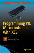
Now I could go into a lot of details of how interrupts work. There is a lot of information written about that and you will find a lot of resources on the Internet if you’re interested. In this book, I take a pragmatic approach. Let’s look at the interrupt in action, shown in Listing 8-1. In this case, we look at the external interrupt as use a pushbutton to trigger an interrupt (see Figure 8-1).
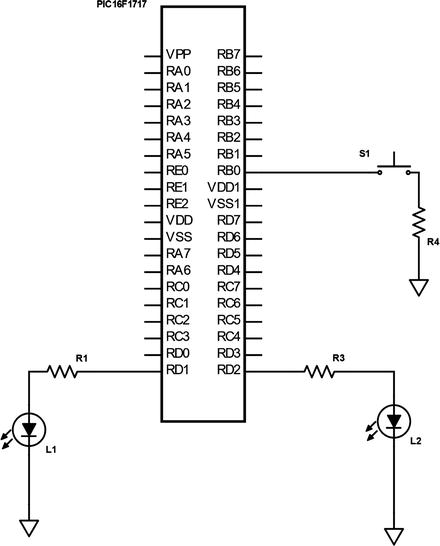
Figure 8-1 External interrupt circuit
Listing 8-1 External Interrupt Code
/** Fle: Main.c* Author: Armstrong Subero* PIC: 16F1717 w/Int OSC @ 16MHz, 5v* Program: 07_Interrupt_External* Compiler: XC8 (v1.38, MPLAX X v3.40)* Program Version: 1.0*** Program Description: This Program Allows PIC16F1717 to toggle an LED based* on the state of a pushbutton interrupt** Hardware Description: An LED is connected via a 10k resistor to PIN D1 and* another LED is connected to PIN D2 and a switch is* connected to PIN B0** Created November 4th, 2016, 8:10 PM*//********************************************************************************Includes and defines******************************************************************************/#include "16F1717_Internal.h"/******************************************************************************** Function: void initMain()** Returns: Nothing** Description: Contains initializations for main** Usage: initMain()******************************************************************************/void initMain(){// Run at 16 MHzinternal_16();/////////////////////////// Configure Ports////////////////////////// Set PIN D1 and D2 as outputTRISDbits.TRISD1 = 0;TRISDbits.TRISD2 = 0;// Turn off LEDLATDbits.LATD1 = 0;// Set PIN B0 as inputTRISBbits.TRISB0 = 1;// Configure ANSELB0ANSELBbits.ANSB0 = 0;// unlock PPSPPSLOCK = 0x55;PPSLOCK = 0xAA;PPSLOCK = 0x00;// Enable weak-pullups globalOPTION_REGbits.nWPUEN = 0;// Enable weak-pullup on PINB0WPUBbits.WPUB0 = 1;//////////////////////////// Configure Interrupts////////////////////////// Set Interrupt pin to pin B0INTPPSbits.INTPPS = 0b01000;// lock PPSPPSLOCK = 0x55;PPSLOCK = 0xAA;PPSLOCK = 0x01;// Trigger on falling edgeOPTION_REGbits.INTEDG = 0;// Clear external interrupt flagINTCONbits.INTF = 0;// Enable external interruptINTCONbits.INTE = 1;// Enable global interruptei();}/******************************************************************************** Function: Main** Returns: Nothing** Description: Program entry point******************************************************************************/void main(void) {initMain();while(1){LATDbits.LATD1 = ~LATDbits.LATD1;__delay_ms(500);}return;}/******************************************************************************** Function: void interrupt isr(void)** Returns: Nothing** Description: Interrupt triggered on pushbutton press******************************************************************************/void interrupt isr(void){// Clear interrupt flagINTCONbits.INTF = 0;// Toggle ledLATDbits.LATD2 = ~LATDbits.LATD2;}
Now that you have a fair understanding of how external interrupts work, we can move on to an interrupt being triggered by some internal mechanism. In this case, we will use an onboard timer to trigger the interrupt. However, we must first look at the operation of timers.
Using Timers
A timer on a microcontroller can count either regular clock pulses (thus making it a timer) or it can count irregular clock pulses (in this mode it is a counter). The PIC16F1717 has five timers. These are Timer 0, Timer 1, and Timers 2, 4, and 6. The timer we will use is Timer 0. We will use this timer because it is ubiquitous among 8-bit PIC® microcontrollers. Since timers can also be used as counters, we sometimes refer to them as timer/counters.
The timer needs a clock pulse to tick. This clock source can either be internal or external to the microcontroller. When we feed internal clock pulses, the timer/counter is in timer mode. However, when we use an external clock pulse, the timer is in counter mode. Timer 0 on the PIC16F1717 can be used as an 8-bit timer/counter.
A Timer 0 will increment every instruction cycle unless a prescaler is used. The prescaler is responsible for slowing down the rate at which Timer 0 counts. The timer has a software selectable prescale value and has eight values from 2-256.
Timer 0 in Timer Mode
We first look at using Timer 0 in timer mode. In order to use the timer, some housekeeping needs to be done. In this mode, we need to clear the TMR0CS bit of the option register. We will then assign a prescaler and to do so, we need to clear the PSA bit of the option register. In this example, we use Timer 0 to flash an LED at precisely 1Hz. To do so, connect the LED to the microcontroller, as shown in Figure 8-2 with RD1 connected to the LED via a 1k resistor.
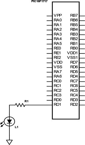
Figure 8-2 Precise LED Flash circuit
Listing 8-2 shows the main code.
Listing 8-2 Timer 0 Timer Mode
/** File: Main.c* Author: Armstrong Subero* PIC: 16F1717 w/Int OSC @ 16MHz, 5v* Program: 04_Timer0* Compiler: XC8 (v1.38, MPLAX X v3.40)* Program Version: 1.0*** Program Description: This Program Allows PIC16F1717 to flash an LED at 1 Hz* on Timer0 overflow** Hardware Description: An LED is connected via a 10k resistor to PIN D1** Created November 4th, 2016, 4:14 PM*//********************************************************************************Includes and defines******************************************************************************/#include "16F1717_Internal.h"// Counter variableint count = 0;/******************************************************************************** Function: void initMain()** Returns: Nothing** Description: Contains initializations for main** Usage: initMain()******************************************************************************/void initMain(){// Run at 16 MHzinternal_16();////////////////////////// Configure Ports//////////////////////// Set PIN D1 as outputTRISDbits.TRISD1 = 0;// Turn off LEDLATDbits.LATD1 = 0;// Set PIN B0 as inputTRISBbits.TRISB0 = 1;// Configure ANSELB0ANSELBbits.ANSB0 = 0;////////////////////////// Configure Timer0//////////////////////// Select timer modeOPTION_REGbits.TMR0CS = 0;// Assign Prescaler to TIMER0OPTION_REGbits.PSA = 0;// Set Prescaler to 256OPTION_REGbits.PS0 = 1;OPTION_REGbits.PS1 = 1;OPTION_REGbits.PS2 = 1;// Zero TimerTMR0 = 0;}/******************************************************************************** Function: Main** Returns: Nothing** Description: Program entry point******************************************************************************/void main(void) {initMain();while(1){// When timer overflows TMR0 interrupt flag will be equal to 1while (INTCONbits.TMR0IF != 1);// Reset flag after overflowINTCONbits.TMR0IF = 0;// Increment countcount++;// Value = fclk / (4 * 256 * 256 * fout)//|-- Frequency out (in Hz)//|-- Prescaler value// Value = 16 000 000 / (262 144)// Value =61.04 for 1 s// Turn on LED for 1 second on timer overflowif (count == 61){LATDbits.LATD1 = 1;count = 0;}// Else turn LED offelse {LATDbits.LATD1 = 0;}}return;}
Timer 0 in Counter Mode
Now we look at using the timer in counter mode. In order to use the timer in counter mode, we need to set the TMR0CS bit of the option register. The steps for assigning the prescaler are the same as for a timer. This code also is the first in the book to utilize the PPS. The PPS in this case is used to designate which pin will be used to count the external clock pulses. The sequence for assigning a peripheral to a pin using PPS is as follows:
Unlock the PPS.
Assign the peripheral to the pins.
Lock the PPS.
You must follow these steps to correctly use the PPS. The global interrupt enable must be configured appropriately, as is shown in the code in Listing 8-3. There is also a function to read Timer 0. When the counter on Timer 0 reaches a particular value, the LED is turned on.
The connections are very simple, as shown in the schematic in Figure 8-3.
Figure 8-3 Counter circuit
Listing 8-3 provides the code.
Listing 8-3 Timer 0 Counter Mode
/** File: Main.c* Author: Armstrong Subero* PIC: 16F1717 w/Int OSC @ 16MHz, 5v* Program: 05_Counter* Compiler: XC8 (v1.38, MPLAX X v3.40)* Program Version: 1.0*** Program Description: This Program Allows PIC16F1717 to turn on an LED after* the counter module on Time0 reaches a specified value* which is detected from external pulses given via a* switch on RB0.** Hardware Description: An LED is connected via a 1k resistor to pin RD1 and* a switch is connected to pin RB0** Created February 23rd, 2017, 5:22 PM*//********************************************************************************Includes and defines******************************************************************************/#include "16F1717_Internal.h"/******************************************************************************** Function: void initMain()** Returns: Nothing** Description: Contains initializations for main** Usage: initMain()******************************************************************************/void initMain(){// Run at 16 MHzinternal_16();////////////////////////// Configure Ports//////////////////////// Set PIN D1 as outputTRISDbits.TRISD1 = 0;// Turn off LEDLATDbits.LATD1 = 0;// Set PIN B0 as inputTRISBbits.TRISB0 = 1;// Configure ANSELB0ANSELBbits.ANSB0 = 0;////////////////////////// Configure Timer0//////////////////////// Select counter modeOPTION_REGbits.TMR0CS = 1;// Assign Prescaler to TIMER0OPTION_REGbits.PSA = 1;bool state = GIE;GIE = 0;PPSLOCK = 0x55;PPSLOCK = 0xAA;PPSLOCKbits.PPSLOCKED = 0x00; // unlock PPST0CKIPPSbits.T0CKIPPS = 0x08; //RB0->TMR0:T0CKI;PPSLOCK = 0x55;PPSLOCK = 0xAA;PPSLOCKbits.PPSLOCKED = 0x01; // lock PPSGIE = state;// Zero TimerTMR0 = 0;// Enable timer0 interrupts and clear interrupt flagINTCONbits.TMR0IE = 1;INTCONbits.TMR0IF = 0;}/******************************************************************************** Function: int ReadTimer(void)** Returns: int readVal;** Description: Returns the value of Timer0** Usage: int x;******************************************************************************/uint8_t ReadTimer0(void){// Read value variableuint8_t readVal;// Set variable to timer0 valuereadVal = TMR0;// return valuereturn readVal;}/******************************************************************************** Function: Main** Returns: Nothing** Description: Program entry point******************************************************************************/void main(void) {initMain();// count variableuint8_t count;while(1){// read timer with countcount = ReadTimer0();// if counter has value of 5if (count == 5){// turn LED onLATDbits.LATD1 = 1;// short delay to see LED on__delay_ms(2000);// zero timerTMR0 = 0;}else{// keep LED offLATDbits.LATD1 = 0;}}return;}
Timer 0 with Interrupts
Now we look at using Timer 0 with interrupts. The code is very simple if you have been following along up to this point, and we will use it to blink an LED every second while simultaneously responding to the pushbutton to toggle another LED. This example demonstrates an important application of interrupts, performing an action in a very deterministic manner.
The circuit is shown in Figure 8-4.

Figure 8-4 Timer interrupt circuit
Listing 8-4 provides the code.
Listing 8-4 Timer 0 with Interrupt
/** File: Main.c* Author: Armstrong Subero* PIC: 16F1717 w/Int OSC @ 16MHz, 5v* Program: 06_Interrupts* Compiler: XC8 (v1.38, MPLAX X v3.40)* Program Version: 1.0*** Program Description: This Program Allows PIC16F1717 flash an LED at a rate* of 1 Hz while responding to a pushbutton input using* a timer0 interrupt*** Hardware Description: An LED is connected via a 1k resistor to PIN D1 and* another LED connected to PIN D2 switch is connected* to PIN B0** Created November 4th, 2016, 7:15 PM*//********************************************************************************Includes and defines******************************************************************************/#include "16F1717_Internal.h"/******************************************************************************** Function: void initMain()** Returns: Nothing** Description: Contains initializations for main** Usage: initMain()******************************************************************************/void initMain(){//////////////////////// Configure Ports/////////////////////// Run at 16 MHzinternal_16();// Set PIN D1, D2 as outputTRISDbits.TRISD1 = 0;TRISDbits.TRISD2 = 0;// Turn off LEDLATDbits.LATD1 = 0;// Set PIN B0 as inputTRISBbits.TRISB0 = 1;// Configure ANSELB0ANSELBbits.ANSB0 = 0;///////////////////////// Configure Timer0//////////////////////// Select timer modeOPTION_REGbits.TMR0CS = 0;// Assign Prescaler to TIMER0OPTION_REGbits.PSA = 0;// Set Prescaler to 256OPTION_REGbits.PS = 0b111;// enable Timer0 interruptINTCONbits.TMR0IE = 1;// enable global interruptsei();}/******************************************************************************** Function: Main** Returns: Nothing** Description: Program entry point******************************************************************************/void main(void) {initMain();while(1){// Toggle LED on PUSH ButtonLATDbits.LATD1 = ~PORTBbits.RB0;}return;}/******************************************************************************** Function: void interrupt isr(void)** Returns: Nothing** Description: Timer0 interrupt at a rate of 1 second******************************************************************************/void interrupt isr(void){static int count = 0;// Reset flag after overflowINTCONbits.TMR0IF = 0;TMR0 = 0;// Increment countcount++;// Value = fclk / (4 * 256 * 256 * fout)// |-- Frequency out (in Hz)// |-- Prescaler value// Value = 16 000 000 / (262 144)// Value = 61.04 for 1 s// Turn on LED for 1 second on timer overflowif (count == 61){LATDbits.LATD2 = 1;count = 0;}// Else keep LED offelse {LATDbits.LATD2 = 0;}}
Using the CCP Module
The PIC16F1717 comes with onboard Capture/Compare/PWM (CCP) modules . The capture mode times the duration of an event. The compare mode triggers an external event after a certain amount of time has passed. We will focus on the PWM. If you need to utilize capture or compare functions, consult the datasheet.
In the last chapter, we briefly examined using PWM for controlling a servo. In this section, we look at using PWM with dedicated hardware.
Understanding PWM
Pulse Width Modulation (PWM) describes a type of signal that can be produced by a microcontroller. However, in order to understand PWM, we must first understand the concept of the duty cycle. A digital signal can be 5v (high) or 0v (low). The amount of time a signal is high is described as the duty cycle of that signal. This is expressed as a percentage. For example, if during a given period of time, a signal is high half of the time and low the other half, it will have a duty cycle of 50%.
Using PWM
Let’s look at using the PWM on the CCP module. A timer is required to use the PWM module. Since Timer 0 is used for so many things, we will use Timer 6 to be the PWM timer.
The PWM module is very important and has a lot of uses. The most popular uses are for light dimming, motor speed control, and generating a modulated signal. In this example, we will use the PWM module to dim an LED. We will run the LED at 50% duty cycle.
Figure 8-5 shows the circuit.
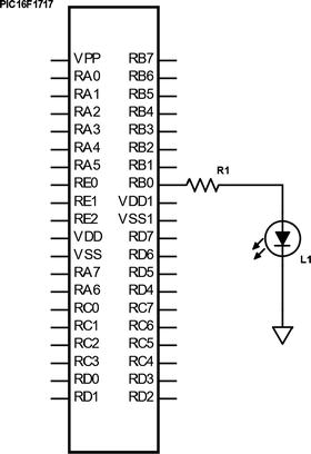
Figure 8-5 PWM circuit
The code is shown in Listing 8-5.
Listing 8-5 CCP PWM
/** File: Main.c* Author: Armstrong Subero* PIC: 16F1717 w/Int OSC @ 16MHz, 5v* Program: 20_PWM* Compiler: XC8 (v1.38, MPLAX X v3.40)* Program Version: 1.0*** Program Description: This Program uses the PWM module of the PIC16F1717*** Hardware Description: An LED is connected to PINB0** Created November 7th, 2016, 5:20 PM*//********************************************************************************Includes and defines******************************************************************************/#include "16F1717_Internal.h"/******************************************************************************** Function: void initMain()** Returns: Nothing** Description: Contains initializations for main** Usage: initMain()******************************************************************************/void initMain(){// Run at 16 MHzinternal_16();// Setup PINB0 as outputTRISBbits.TRISB0 = 0;/////////////////////// Configure Timer6/////////////////////// Select PWM timer as Timer6CCPTMRSbits.C1TSEL = 0b10;// Enable timer Increments every 250 ns (16MHz clock) 1000/(16/4)// Period = 256 x 0.25 us = 64 us// Crystal Frequency// PWM Freq = -----------------------------------------// (PRX + 1) * (TimerX Prescaler) * 4//PWM Frequency = 16 000 000 / 256 * 1 * 4//PWM Frequency = 15.625 kHz// Prescale = 1T6CONbits.T6CKPS = 0b00;// Enable Timer6T6CONbits.TMR6ON = 1;// Set timer periodPR6 = 255;// Configure CCP1// LSB's of PWM duty cycle = 00CCP1CONbits.DC1B = 00;// Select PWM modeCCP1CONbits.CCP1M = 0b1100;PPSLOCK = 0x55;PPSLOCK = 0xAA;PPSLOCKbits.PPSLOCKED = 0x00; // unlock PPS// Set RB0 to PWM1RB0PPSbits.RB0PPS = 0b01100;PPSLOCK = 0x55;PPSLOCK = 0xAA;PPSLOCKbits.PPSLOCKED = 0x01; // lock PPS}/******************************************************************************** Function: Main** Returns: Nothing** Description: Program entry point******************************************************************************/void main(void) {initMain();while(1){// Run at 50% duty cycle @ 15.625 kHzCCPR1L = 127;}return;}
The code also contains a formula for calculating the frequency of the PWM module, which is important for applications such as motor control.
Project: Using PWM with a Motor Driver
In the previous chapter on interfacing actuators, we looked at a simple way of driving a motor. In this section, we look at the typical way of driving a motor, which is to use a dedicated motor driver, IC. Using a dedicated IC allows us to easily control the speed and direction of the motor and offers better general control of the motor.
The motor driver that we will use is the common SN754410, which has two H-Bridges onboard and can handle up to 36 volts at 1A per driver. In addition to having decent specs, this driver is also low cost, which makes it an attractive option for general-purpose applications.
When teaching someone to do something the first time, it is nice to provide a lot of hand-holding. After all, beginners need a lot of hand-holding to properly understand concepts. In this project, however, I let you do a little research to complete it. I provide the connections in the text as well as in the code, and your job is to connect the motor driver and motor to the microcontroller without a schematic. Think you can handle that? Let’s begin!
The motor is connected as follows:
1: Enables motor one, connect to 5v
2: Connects to forward PWM channel (motor 1)
3: Motor 1 +
4-5: GND
6: Motor 1
7: Connects to reverse PWM channel (motor 1)
8: +VE Motor Power In
12-13: GND
16: 5v
We will run the motor for five seconds in one direction, turn it off for two seconds, and then run it again for five seconds in the other direction.
The code is provided in Listing 8-6.
Listing 8-6 PWM Motor
/** File: Main.c* Author: Armstrong Subero* PIC: 16F1717 w/Internal OSC @ 16MHz, 5v* Program: I04_H_Bridge* Compiler: XC8 (v1.38, MPLAX X v3.40)* Program Version: 1.0*** Program Description: This demonstrates using a SN754410 H-Bridge with a* DC motor with a PIC microcontroller.** Hardware Description: A generic brushed hobby DC motor is connected to the* SN754410 as per standard connections. The PWM signals* are emanating from RB0 and RB1 for forward and reverse* signals respectively.*** Created January 15th, 2017, 11:36 AM*//********************************************************************************Includes and defines******************************************************************************/#include "16F1717_Internal.h"/******************************************************************************** Function: void initMain()** Returns: Nothing** Description: Contains initializations for main** Usage: initMain()******************************************************************************/void initMain(){// Run at 16 MHzinternal_16();////////////////////// Configure Ports///////////////////// Set PIN B0 as outputTRISBbits.TRISB0 = 0;// Set PIN B1 as outputTRISBbits.TRISB1 = 0;// Turn off analogANSELB = 0;/////////////////////// Configure Timer6/////////////////////// Select PWM timer as Timer6 for CCP1 and CCP2CCPTMRSbits.C1TSEL = 0b10;CCPTMRSbits.C2TSEL = 0b10;// Enable timer Increments every 250 ns (16MHz clock) 1000/(16/4)// Period = 256 x 0.25 us = 64 us// Crystal Frequency//PWM Freq = -----------------------------------------//(PRX + 1) * (TimerX Prescaler) * 4//PWM Frequency = 16 000 000 / 256 * 1 * 4//PWM Frequency = 15.625 kHz// Prescale = 1T6CONbits.T6CKPS = 0b00;// Enable Timer6T6CONbits.TMR6ON = 1;// Set timer periodPR6 = 255;//////////////////////////// Configure PWM/////////////////////////// Configure CCP1// LSB's of PWM duty cycle = 00CCP1CONbits.DC1B = 00;// Select PWM modeCCP1CONbits.CCP1M = 0b1100;// Configure CCP2// LSB's of PWM duty cycle = 00CCP2CONbits.DC2B = 00;// Select PWM modeCCP2CONbits.CCP2M = 0b1100;//////////////////////////////// Configure PPS/////////////////////////////PPSLOCK = 0x55;PPSLOCK = 0xAA;PPSLOCKbits.PPSLOCKED = 0x00; // unlock PPS// Set RB0 to PWM1RB0PPSbits.RB0PPS = 0b01100;// Set RB1 to PWM2RB1PPSbits.RB1PPS = 0b01101;PPSLOCK = 0x55;PPSLOCK = 0xAA;PPSLOCKbits.PPSLOCKED = 0x01; // lock PPS}/******************************************************************************** Function: Main** Returns: Nothing** Description: Program entry point******************************************************************************/void main(void) {initMain();while(1){// Run at approx. 20% duty cycle @ 15.625 kHz for 5 sec// ForwardCCPR1L = 192;CCPR2L = 0;__delay_ms(5000);CCPR1L = 0;CCPR2L = 0;__delay_ms(2000);// ReverseCCPR1L = 0;CCPR2L = 192;__delay_ms(5000);}return;}
Project: Using CCP and Dedicated PWM with RGB LED
As was previously mentioned, an important use of PWM is in lighting applications. In this project, we will use the PWM to drive a tri-color LED. A tri-color LED (RGB LED) consists of three LEDs in a single package. By varying the intensity of each of these three colors, any other color can be generated.
We will use the PWM to change the average voltage flowing through each individual LED and let our persistence of vision do the rest.
In the code in Listing 8-7, we also utilize the built-in PWM module of the PIC® microcontroller and we use a dedicated PWM3 channel.
Listing 8-7 PWM RGB
/** File: Main.c* Author: Armstrong Subero* PIC: 16F1717 w/Internal OSC @ 16MHz, 5v* Program: I08_RGB_LED* Compiler: XC8 (v1.41, MPLAX X v3.55)* Program Version: 1.0*** Program Description: This demonstrates using a RGB LED with PIC16F1717** Hardware Description: A RGB LED is connected as follows:* Red - RB0* Green – RB3* Blue – RB2*** Created Tuesday 18th, April, 2017, 11:53 AM*//********************************************************************************Includes and defines******************************************************************************/#include "16F1717_Internal.h"/*Value for PWM1*/void PWM1_LoadDutyValue(uint16_t dutyValue) {// Writing to 8 MSBs of pwm duty cycle in CCPRL registerCCPR1L = ((dutyValue & 0x03FC) >> 2);// Writing to 2 LSBs of pwm duty cycle in CCPCON registerCCP1CON = (CCP1CON & 0xCF) | ((dutyValue & 0x0003) << 4);}/*Value for PWM2*/void PWM2_LoadDutyValue(uint16_t dutyValue) {// Writing to 8 MSBs of pwm duty cycle in CCPRL registerCCPR2L = ((dutyValue & 0x03FC) >> 2);// Writing to 2 LSBs of pwm duty cycle in CCPCON registerCCP2CON = (CCP2CON & 0xCF) | ((dutyValue & 0x0003) << 4);}/*Value for PWM3*/void PWM3_LoadDutyValue(uint16_t dutyValue) {// Writing to 8 MSBs of PWM duty cycle in PWMDCH registerPWM3DCH = (dutyValue & 0x03FC) >> 2;// Writing to 2 LSBs of PWM duty cycle in PWMDCL registerPWM3DCL = (dutyValue & 0x0003) << 6;}/*Value for RGB LED*/void RGB_LoadValue(uint16_t red, uint16_t green, uint16_t blue){PWM1_LoadDutyValue(red);PWM2_LoadDutyValue(green);PWM3_LoadDutyValue(blue);}/******************************************************************************** Function: void initMain()** Returns: Nothing** Description: Contains initializations for main** Usage: initMain()******************************************************************************/void initMain(){// Run at 16 MHzinternal_16();////////////////////// Configure Ports///////////////////// Set PIN B0 as outputTRISBbits.TRISB0 = 0;// Set PIN B1 as outputTRISBbits.TRISB1 = 0;// Set PIN B2 as outputTRISBbits.TRISB2 = 0;// Turn off analogANSELB = 0;/////////////////////// Configure Timer6/////////////////////// Select PWM timer as Timer6 for CCP1 and CCP2CCPTMRSbits.C1TSEL = 0b10;CCPTMRSbits.C2TSEL = 0b10;// Enable timer Increments every 250 ns (16MHz clock) 1000/(16/4)// Period = 256 x 0.25 us = 64 us// Crystal Frequency//PWM Freq = -----------------------------------------//(PRX + 1) * (TimerX Prescaler) * 4//PWM Frequency = 16 000 000 / 256 * 1 * 4//PWM Frequency = 15.625 kHz// Prescale = 1T6CONbits.T6CKPS = 0b00;// Enable Timer6T6CONbits.TMR6ON = 1;// Set timer periodPR6 = 255;//////////////////////////// Configure PWM/////////////////////////// Configure CCP1// LSB's of PWM duty cycle = 00CCP1CONbits.DC1B = 00;// Select PWM modeCCP1CONbits.CCP1M = 0b1100;// Configure CCP2// LSB's of PWM duty cycle = 00CCP2CONbits.DC2B = 00;// Select PWM modeCCP2CONbits.CCP2M = 0b1100;// Configure PWM 3// PWM3EN enabled, PWM3POL active highPWM3CON = 0x80;// PWM3DCH 127PWM3DCH = 0x7F;// PWM3DCL 192PWM3DCL = 0xC0;// Select timer6CCPTMRSbits.P3TSEL = 0b10;//////////////////////////////// Configure PPS/////////////////////////////PPSLOCK = 0x55;PPSLOCK = 0xAA;PPSLOCKbits.PPSLOCKED = 0x00; // unlock PPS// Set RB0 to PWM1RB0PPSbits.RB0PPS = 0b01100;// Set RB1 to PWM2RB1PPSbits.RB1PPS = 0b01101;// Set RB2 to PWM3RB2PPSbits.RB2PPS = 0x0E;PPSLOCK = 0x55;PPSLOCK = 0xAA;PPSLOCKbits.PPSLOCKED = 0x01; // lock PPS}/******************************************************************************** Function: Main** Returns: Nothing** Description: Program entry point******************************************************************************/void main(void) {initMain();// All channels initially 0PWM1_LoadDutyValue(0);PWM2_LoadDutyValue(0);PWM3_LoadDutyValue(0);while(1){// RedRGB_LoadValue(512, 0, 0);__delay_ms(1000);// GreenRGB_LoadValue(0, 512, 0);__delay_ms(1000);// BlueRGB_LoadValue(0, 0, 512);__delay_ms(1000);// YellowRGB_LoadValue(192, 192, 0);__delay_ms(1000);// PurpleRGB_LoadValue(192, 0, 192);__delay_ms(1000);// AquamarineRGB_LoadValue(0, 512, 512);__delay_ms(1000);}return;}
Conclusion
This concludes this chapter, where we looked at a few more onboard modules of the PIC® microcontroller. We looked at interrupts, which allow the microcontroller to instantly jump to a specific task, timers, which count regular clock pulses, counters, which count irregular pulses, and PWM, which is very useful in microcontroller applications such as lighting and motor control.