
Data Conversion
Many times when you’re working with microcontrollers, you might need to use analog to digital and digital to analog converters. Devices that are responsible for data conversion between digital and analog forms are ubiquitous in our modern world. Devices like smartphones, drones, and televisions depend on data conversion to work. Converters are crucial to the operation of most modern devices.
ADC (Analog to Digital Conversion)
Analog to digital conversion (ADC) is one of the most important onboard modules of the PIC® microcontroller. The reason is very simple—we live in an analog world. Computers process all their information in digital format; however many transducers, which when electronic are called sensors, output their values as voltage. The ADC converts these analog voltages into a digital representation that the processor can understand.
The ADC has a specific number of bits of resolution. These can be from 8 to 32 bits. The higher the resolution of the ADC, the greater the number of steps there will be from the minimum voltage to the maximum voltage. The PIC16F1717 has a 10-bit resolution ADC. What this means is that the ADC can read a voltage in steps from 0 to 1023. Here is the code to interface the ADC:
In this example, we use a potentiometer connected to the microcontroller to demonstrate the use of the ADC module. The potentiometer will vary the voltage between 5v (step 1023) down to 0v (step 0), which is connected to a pin that has been configured for analog input on the PIC® microcontroller.
Listing 11-1 provides the code to interface the ADC.
Listing 11-1 ADC Source
/** File: Main.c* Author: Armstrong Subero* PIC: 16F1717 w/Int OSC @ 16MHz, 5v* Program: 16_ADC* Compiler: XC8 (v1.38, MPLAX X v3.40)* Program Version: 1.0*** Program Description: This Program Allows PIC16F1717 to demonstrate the on* board 10 bit ADC module. A 10k potentiometer is* connected to PIN RA0 and a 10 bit ( 0 - 1023) conversion* result is displayed on the LCD.*** Hardware Description: An HD44780 compatible LCD is connected to PORTD of the* microcontroller as follows:** RS ---> RD2* R/W ---> GND* EN ---> RD3* D4 ---> RD4* D5 ---> RD5* D6 ---> RD6* D7 ---> RD7** A 10k pot is connected to PIN RA0.*** Created November 7th, 2016, 11:05 AM*//********************************************************************************Includes and defines******************************************************************************/#include "16F1717_Internal.h"#include "LCD.h"/******************************************************************************** Function: void initMain()** Returns: Nothing** Description: Contains initializations for main** Usage: initMain()******************************************************************************/void initMain(){// Run at 16 MHzinternal_16();// Set PIN D1 as outputTRISDbits.TRISD1 = 0;// Turn off LEDLATDbits.LATD1 = 0;// Setup PORTDTRISD = 0;ANSELD = 0;// Set PIN B0 as inputTRISBbits.TRISB0 = 1;// Configure ANSELB0ANSELBbits.ANSB0 = 0;// Set A0 as inputTRISAbits.TRISA0 = 1;// Set A0 as analogANSELAbits.ANSA0 = 1;////////////////////// Configure ADC///////////////////// Fosc/32 ADC conversion time is 2.0 usADCON1bits.ADCS = 0b010;// Right justifiedADCON1bits.ADFM = 1;// Vref- is VssADCON1bits.ADNREF = 0;// Vref+ is VddADCON1bits.ADPREF = 0b00;// Set input channel to AN0ADCON0bits.CHS = 0b00000;// Zero ADRESL and ADRESHADRESL = 0;ADRESH = 0;// Initialize LCDLcd_Init();__delay_ms(100);Lcd_Clear();}/******************************************************************************** Function: Main** Returns: Nothing** Description: Program entry point******************************************************************************/void main(void) {initMain();// variable to store conversion resultint result;while(1){// Turn ADC onADCON0bits.ADON = 1;// Sample CH0__delay_us(10);ADCON0bits.GO = 1;while (ADCON0bits.GO_nDONE);// Store ADC resultresult = ((ADRESH<<8)+ADRESL);// Write result to LCDLcd_Set_Cursor(1,1);__delay_ms(5);Lcd_Write_Integer(result);// Update every second__delay_ms(1000);Lcd_Clear();}return;}
Project: Digital Thermometer
In this section, we look at building a digital thermometer using the PIC® microcontroller. The ADC onboard the microcontroller will read the LM34 temperature sensor and output the corresponding voltage (see Figure 11-1). The LM34 has a scale factor of 1 degree Fahrenheit for every 10 millivolts. Thus, in order to convert the voltage to temperature, there are three stages. The steps are as follows:
Get the results according to the scale factor.
Convert that result to Fahrenheit.
Convert Fahrenheit to Celsius.
The code is pretty straightforward, as shown in Listing 11-2.
Listing 11-2 Temperature Code
/** File: Main.c* Author: Armstrong Subero* PIC: 16F1717 w/Int OSC @ 16MHz, 5v* Program: P01_Temperature* Compiler: XC8 (v1.41, MPLAX X v3.55)* Program Version: 1.0***Program Description: This Program gives a reading in Celsius based on the* output of a LM34 temperature sensor. The output is* displayed on an OLED.** Hardware Description: A LM34 is connected to PIN E0 and a SSD1306 OLED is* connected to the I2C bus.*** Created March 22nd, 2017, 8:15 PM*//********************************************************************************Includes and defines******************************************************************************/#include "16F1717_Internal.h"#include "I2C.h"#include "oled.h"/******************************************************************************** Function: void initMain()** Returns: Nothing** Description: Contains initializations for main** Usage: initMain()******************************************************************************/void initMain(){// Run at 16 MHzinternal_16();/////////////////////// Setup I2C//////////////////// Setup pins for I2CANSELCbits.ANSC4 = 0;ANSELCbits.ANSC5 = 0;TRISCbits.TRISC4 = 1;TRISCbits.TRISC5 = 1;PPSLOCK = 0x55;PPSLOCK = 0xAA;PPSLOCKbits.PPSLOCKED = 0x00; // unlock PPSRC4PPSbits.RC4PPS =0x0011; //RC4->MSSP:SDA;SSPDATPPSbits.SSPDATPPS =0x0014; //RC4->MSSP:SDA;SSPCLKPPSbits.SSPCLKPPS =0x0015; //RC5->MSSP:SCL;RC5PPSbits.RC5PPS =0x0010; //RC5->MSSP:SCL;PPSLOCK = 0x55;PPSLOCK = 0xAA;PPSLOCKbits.PPSLOCKED = 0x01; // lock PPS////////////////////// Configure ADC///////////////////// Fosc/32 ADC conversion time is 2.0 usADCON1bits.ADCS = 0b010;// Right justifiedADCON1bits.ADFM = 1;// Vref- is VssADCON1bits.ADNREF = 0;// Vref+ is VddADCON1bits.ADPREF = 0b00;// Set input channel to AN0ADCON0bits.CHS = 0x05;// Zero ADRESL and ADRESHADRESL = 0;ADRESH = 0;ANSELEbits.ANSE0 = 1;}/******************************************************************************** Function: Main** Returns: Nothing** Description: Program entry point******************************************************************************/void main(void) {initMain();// Initialize I2CI2C_Init();// Initialize OLEDOLED_Init();// clear OLEDOLED_Clear();// result to store ADC conversionfloat result;// variables for conversionfloat conversion10;float farenheit;float celsius;while(1){// Turn ADC onADCON0bits.ADON = 1;// Sample CH0__delay_us(10);ADCON0bits.GO = 1;while (ADCON0bits.GO_nDONE);// Store ADC resultresult = ((ADRESH<<8)+ADRESL);// 10 bit conversionconversion10 = (result * 5000)/1024 ;// to Fahrenheitfarenheit = conversion10 / 10;// to Celsiuscelsius = (farenheit - 32) * 5/9;// Display temperatureOLED_YX(0, 0);OLED_Write_String("Temp: ");OLED_YX(1, 0);OLED_Write_Integer((int)celsius);// Update every second__delay_ms(2000);}return;}
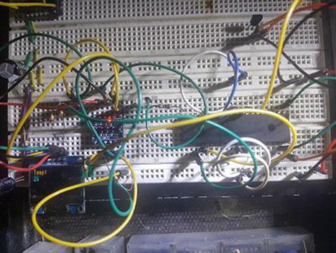
Figure 11-1 Temperature results
DAC (Digital to Analog Converter)
In addition to an ADC module, the PIC16F1717 also provides a DAC onboard. The digital to analog converter (DAC) is the brother of the ADC, except it does the exact opposite. Instead of converting an analog signal to a digital one, as its name suggests, it converts a digital signal to an analog one. The PIC16F1717 has two onboard DACs and they include an 8-bit DAC and a 5 bit-DAC. In this example, we use the 8-bit DAC to output a waveform on pin RA2, which can be viewed with an oscilloscope.
Listing 11-3 shows the code to use the DAC onboard the PIC16F1717 and generate a waveform.
Listing 11-3 DAC Source
/** File: Main.c* Author: Armstrong Subero* PIC: 16F1717 w/Int OSC @ 16MHz, 5v* Program: 14_DAC_8_Bit* Compiler: XC8 (v1.38, MPLAX X v3.40)* Program Version: 1.0*** Program Description: This Program Allows PIC16F1717 DAC1 to generate a* waveform on PIN RA2*** Hardware Description: An Oscilloscope probe is connected to pin RA2*** Created November 7th, 2016, 10:08 AM*//********************************************************************************Includes and defines******************************************************************************/#include "16F1717_Internal.h"/******************************************************************************** Function: void initMain()** Returns: Nothing** Description: Contains initializations for main** Usage: initMain()******************************************************************************/void initMain(){// Run at 16 MHzinternal_16();// Set PIN D1 as outputTRISDbits.TRISD1 = 0;TRISDbits.TRISD2 = 0;// Turn off LEDLATDbits.LATD1 = 0;LATDbits.LATD1 = 0;//////////////////////// Configure DAC/////////////////////// DAC enabledDAC1CON0bits.DAC1EN = 1;// DACOUT pin enabledDAC1CON0bits.DAC1OE1 = 1;// +ve source is VddDAC1CON0bits.DAC1PSS = 0;// -ve source is VssDAC1CON0bits.DAC1NSS = 0;// Initial output is 0vDAC1CON1bits.DAC1R = 0;}/******************************************************************************** Function: Main** Returns: Nothing** Description: Program entry point******************************************************************************/void main(void) {initMain();while(1){DAC1CON1++;}return;}
Conclusion
This chapter looked at using the onboard ADC and DAC of the PIC® microcontroller. You saw how to used these modules to create a thermometer and generate a simple waveform.